
w w w . t n b . c aD64
SS401E - SS802E - SS803E - SS804E
MM801
SS18
B3/8-6
Meter Sockets
Pole Line Hardware
Heavy-Duty Spool Rack (200 A)
Cat. No. No. of Wires Overall Length (in.)
Weight (100 pcs)Std. Pkg.
lb. kgSS401E 1 9-1/2 300 136.3 10SS802E 2 17-1/2 520 236.3
5SS803E 3 25-1/2 780 354.5
SS804E 4 33-1/2 1040 472.7Racks are made of 1 in. x 1 in. x 1/8 in. angle iron, assembled complete with 5/8 in. diameter rod and 3/16 in. diameter brasscotter pin. All ferrous parts are hot dip galvanized. Insulator cat. no. IB135 must be ordered separately (included in SS401E only).
Anti-Vibration Kit for Spool Rack
No de cat. DescriptionWeight
(100 pcs) Std. Pkg.
lb. kg
B3/8-6 2 bolts 3/8 x 6 in. long c/w 1 washer, 1 lockwasher and 1 nut finished hot galv. 100 45.35 5
Add suffix “NI” if insulator is not required. Constructed of 1-1/4 in. x 1/2 in. x 1/8 in. steel channel, has 5/8 in. diam. pin and C/W No. IB135 insulator, 11/16 in. round mounting hole. All ferrous parts are hot dip galvanized.
Québec Construction Code, Chapter V – Electricity, Article 6-112 (6) requires that the spool rack be tightly bolted and attached to structural members of a minimum thickness of 88mm overall, if the framed structure is made of wood.
Hydro-Québec, Low-Voltage Electrical Service, Standard E21-10, Article 2.2.1, 2.2.2 and Blue Book read as follows:
2.2.1 SUPPLY AND INSTALLATIONThe master electrician shall, at the customer’s expense, supply and install the spool rack in accordance with Code requir ments and with the recommendations of the Régie du bâtiment du Québec, particularly to avoid any problem due to vibrations. The customer retains ownership of the spool rack.
2.2.2 LOCATIONThe spool rack may be attached to the exterior wall of a building or to a customer pole, service mast or other support structure. The master electrician shall ensure that the service loop is secured firmly to the building in a location not conducive to vibrations, and shall strengthen the structure, if necessary, at the customer’s expense. The location must also allow the meter to be installed in a readily accessible place.
PLAN VIEW ELEVATION VIEW
Bolt (mandatory)
Lag screw (prohibited)
Note: Interior insulation and exterior wall are not shown for more clarity. Figure 2: Spool rack installation (wooden structure). Source: Régie du bâtiment du Québec. Can also be used in all Provinces
Min. 38 mmMin.
38 mm
Medium-Duty Spool Rack (100 A)
Cat. No. No. of Wires Overall Dia. (in.)
Weight (100 pcs)Std. Pkg.
lb. kg
SS18 1 6-1/2 150 68.1 25
Medium duty spool rack is furnished complete with cat. no. IB134 insulator. All ferrous parts are hot dip galvanized.
Heavy-Duty Spool Rack (400 A)
Cat. No. No. of Wires Overall Length (in.)
Weight (100 pcs)Std. Pkg.
lb. kgMM801 1 3 360 163.2 10

w w w . t n b . c a D65
IB400
603TH-604TH
AN422 - AN422KIT - AN423
AN424
IB134 - IB135
IB900
Meter Sockets
Pole Line Hardware
72 in.24 in.
96 in.
Tripod insulator (200 A)
Cat. No. Height(in.)
Overall Dia. (in.)
Weight (100 pcs)Std. Pkg.
lb. kgIB400 3-1/2 3-1/4 125 56.8 25
2-1/8 in.
2-1/8 in.
2-1/8 in.
2-5/8 in.
Insulators (100–400 A)
Cat. No. Ampere Height(in.)
Diameter (in.)
Hole Dia.(in.)
Weight (100 pcs)Std. Pkg.
lb. kgIB134 100 2 2-1/4 9/16 40 18.1 100IB135 200 and 400 3 3 13/16 115 52.2 50
Porcelain insulator securely held in the hot galvanized steel clevis by a cotter pin.
Screw type insulator (100 A)
Cat. No. Insulator Length (in.)
Pull OutStrength
Weight (100 pcs)Std. Pkg.
lb. kgIB900 3 1500 lb 87 39.5 25
Porcelain insulator securely held in the hot galvanized steel clevis by a cotter pin.
Light-Duty Clevis (100 A)
Cat. No. Mounting HoleWeight (100 pcs)
Std. Pkg.lb. kg
AN422 11/16 in. round 90 40.9 25
AN422KIT 11/16 in. round c/w bolts and washers – – 1
AN423 9/16 in. x 9/16 in. square 90 40.9 25Add suffix “NI” if insulator is not required. Constructed of 1/8 in. x 1 in. flat mild steel, has 3/8 in. diam. pin and C/W No. IB134 insulator, mounting hole as per table above. All ferrous parts are hot dip galvanized.
Clevis (200 A)
Cat. No.Weight (100 pcs)
Std. Pkg.lb. kg
AN424 100 45.4 25Add suffix “NI” if insulator is not required. Constructed of 1/8 in. x 1-1/4 in. flat mild steel, has 3/8 in. diam. pin and C/W No. IB134 insulator, 3/8 in. round mounting hole. All ferrous parts are hot dip galvanized.
Tripods (200 A)
Cat. No. No. of WiresWeight (100 pcs)
Std. Pkg.lb. kg
603TH* 3 4000 1818.1 1604TH — 3800 1727.2 1
Type “T” (medium duty) is constructed of 1 in. x 1 in. x 1/8 in. angle iron. Type “TH” (heavy duty) is constructed of 1-1/4 in. x 1-1/4 in. x 3/16 in. angle iron. All ferrous parts are hot dip galvanized. * Complete with IB400.
w w w . t n b . c aD66
AN428S
AN428
AN117
AN122
Meter Sockets
3-1/4 in.
4 in.
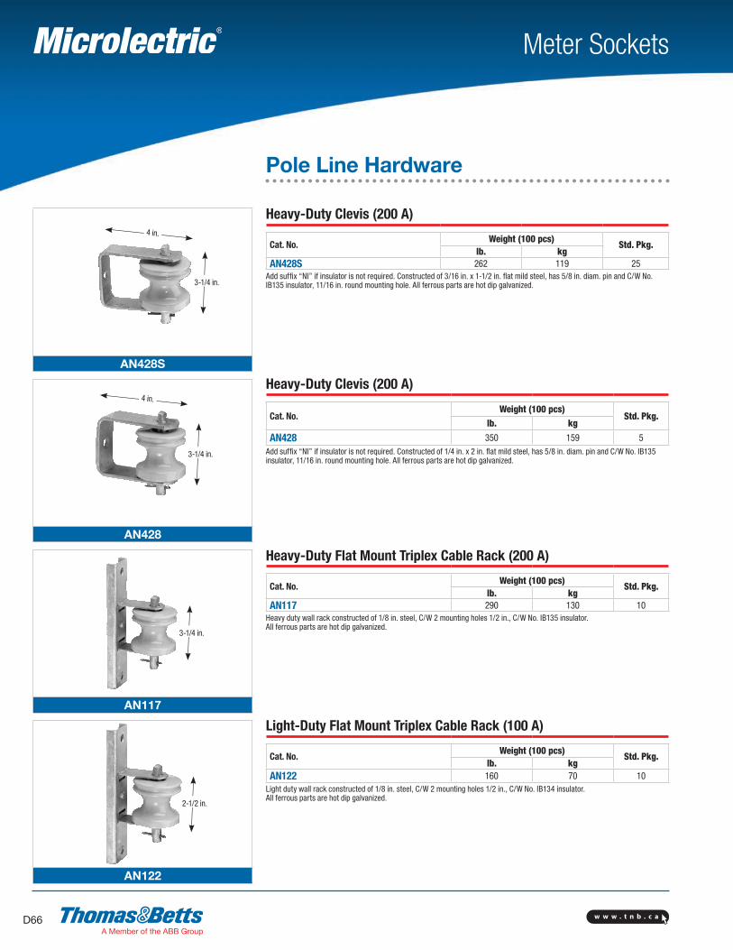
Heavy-Duty Clevis (200 A)
Cat. No.Weight (100 pcs)
Std. Pkg.lb. kg
AN428S 262 119 25Add suffix “NI” if insulator is not required. Constructed of 3/16 in. x 1-1/2 in. flat mild steel, has 5/8 in. diam. pin and C/W No. IB135 insulator, 11/16 in. round mounting hole. All ferrous parts are hot dip galvanized.
Heavy-Duty Clevis (200 A)
Cat. No.Weight (100 pcs)
Std. Pkg.lb. kg
AN428 350 159 5Add suffix “NI” if insulator is not required. Constructed of 1/4 in. x 2 in. flat mild steel, has 5/8 in. diam. pin and C/W No. IB135 insulator, 11/16 in. round mounting hole. All ferrous parts are hot dip galvanized.
Heavy-Duty Flat Mount Triplex Cable Rack (200 A)
Cat. No.Weight (100 pcs)
Std. Pkg.lb. kg
AN117 290 130 10Heavy duty wall rack constructed of 1/8 in. steel, C/W 2 mounting holes 1/2 in., C/W No. IB135 insulator. All ferrous parts are hot dip galvanized.
Light-Duty Flat Mount Triplex Cable Rack (100 A)
Cat. No.Weight (100 pcs)
Std. Pkg.lb. kg
AN122 160 70 10Light duty wall rack constructed of 1/8 in. steel, C/W 2 mounting holes 1/2 in., C/W No. IB134 insulator. All ferrous parts are hot dip galvanized.
Pole Line Hardware
3-1/4 in.
4 in.
3-1/4 in.
2-1/2 in.

w w w . t n b . c a D67
AL425
AL426
AU427
AU429
Meter Sockets
Pole Line Hardware
2-1/8 in.
3-1/4 in.
4-3/16 in.
4-3/16 in.
3-1/4 in.
3-1/4 in.
3-3/4 in.
3-3/4 in.
Clevis (100 A)
Cat. No.Weight (100 pcs)
Std. Pkg.lb. kg
AL425 162 73.6 20Add suffix “NI” if insulator is not required. Constructed of 3/16 in. x 1-1/2in. flat mild steel, has 1/2” diam. pin and C/W No. IB134 insulator, 11/16 in. round mounting hole. All ferrous parts are hot dip galvanized.
Clevis (200 A)
Cat. No.Weight (100 pcs)
Std. Pkg.lb. kg
AL426 262 119 10Add suffix “NI” if insulator is not required. Constructed of 3/16 in. x 1-1/2 in. flat mild steel, has 5/8 in. diam. pin and C/W No. IB135 insulator, 11/16 in. round mounting hole. All ferrous parts are hot dip galvanized.
Clevis (200 A)
Cat. No.Weight (100 pcs)
Std. Pkg.lb. kg
AU427 265 120.4 10Add suffix “NI” if insulator is not required. Constructed of 1-1/4 in. x 1/2 in. x 1/8 in. steel channel, has 5/8 in. diam. pin and C/W No. IB135 insulator, 11/16 in. round mounting hole. All ferrous parts are hot dip galvanized.
Clevis (200 A)
Cat. No.Weight (100 pcs)
Std. Pkg.lb. kg
AU429 240 109 10Add suffix “NI” if insulator is not required. Constructed of 1 in. x 1/2 in. x 1/8 in. steel channel, has 5/8 in. diam. pin C/W No. IB135 insulator, 11/16 in. square hole. All ferrous parts are hot dip galvanized.

w w w . t n b . c aD68
SW409
SW410
SW411
SW411S
Meter Sockets
Pole Line Hardware
Clevis (100 A)
Cat. No.Weight (100 pcs)
Std. Pkg.lb. kg
SW409 100 45.4 25Add suffix “NI” if insulator is not required. Constructed of 1/8 in. x 1 in. curved mild steel, has 3/8 in. diam. swivel type pin C/W No. IB134 insulator, 2 mtg. holes 7/16 in. round. All ferrous parts are hot dip galvanized.
Clevis (100 A)
Cat. No.Weight (100 pcs)
Std. Pkg.lb. kg
SW410 180 81.8 20Add suffix “NI” if insulator is not required. Undereave/off the wall bracket constructed of 3/16 in. x 1-1/2 in. flat mild steel, C/W No. IB132 insulator. Three 3/8 in. round mtg. holes. All ferrous parts are hot dip galvanized.
Clevis (100 A)
Cat. No.Weight (100 pcs)
Std. Pkg.lb. kg
SW411 125 56.8 20Add suffix “NI” if insulator is not required. Constructed of 1/8 in. x 3/4 in. curved mild steel, has 3/8 in. diam. swivel type pin C/W No. IB134 insulator, strong 1/4 in. angle bracket, 11/16 in. round mtg. hole. All ferrous parts are hot dip galvanized.
Clevis (100 A)
Cat. No.Weight (100 pcs)
Std. Pkg.lb. kg
SW411S 125 56.8 20Add suffix “NI” if insulator is not required. Constructed of 1/8 in. x 3/4 in. curved mild steel, has 3/8 in. diam. swivel type pin C/W No. IB134 insulator, strong 1/4 in. bracket, 11/16 in. round mtg. hole. All ferrous parts are hot dip galvanized.
2-1/4 in.
2-1/4 in.
2-1/4 in.
2 in.
10 in.
6 in. 4 in.
2-1/2 in.
4-1/2 in.
w w w . t n b . c a D69
SW412
SW412-MH
Meter Sockets
Pole Line Hardware
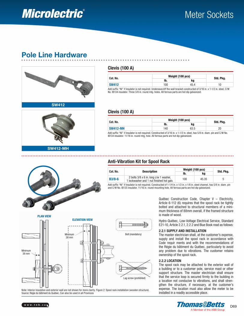
PLAN VIEWELEVATION VIEW
Bolt (mandatory)
Lag screw (prohibited)
Note: Interior insulation and exterior wall are not shown for more clarity. Figure 2: Spool rack installation (wooden structure). Source: Régie du bâtiment du Québec. Can also be used in all Provinces
Clevis (100 A)
Cat. No.Weight (100 pcs)
Std. Pkg.lb. kg
SW412 100 45.4 10Add suffix “NI” if insulator is not required. Undereave/off the wall bracket constructed of 3/16 in. x 1-1/2 in. steel, C/W No. IB134 insulator. Three 3/8 in. round mtg. holes. All ferrous parts are hot dip galvanized.
Clevis (100 A)
Cat. No.Weight (100 pcs)
Std. Pkg.lb. kg
SW412-MH 140 63.5 20Add suffix “NI” if insulator is not required. Constructed of 3/16 in. x 1-1/2 in. steel, has 5/8 in. diam. pin and C/W No. IB134 insulator. 11/16 in. round mtg. hole. All ferrous parts are hot dip galvanized.
Anti-Vibration Kit for Spool Rack
Cat. No. DescriptionWeight (100 pcs)
Std. Pkg.lb. kg
B3/8-6 2 bolts 3/8 x 6 in. long c/w 1 washer, 1 lockwasher and 1 nut finished hot galv. 100 45.35 5
Add suffix “NI” if insulator is not required. Constructed of 1-1/4 in. x 1/2 in. x 1/8 in. steel channel, has 5/8 in. diam. pin and C/W No. IB135 insulator, 11/16 in. round mounting hole. All ferrous parts are hot dip galvanized.
Minimum38 mm
Minimum38 mm
Québec Construction Code, Chapter V – Electricity, Article 6-112 (6) requires that the spool rack be tightly bolted and attached to structural members of a mini-mum thickness of 88mm overall, if the framed structure is made of wood.
Hydro-Québec, Low-Voltage Electrical Service, Standard E21-10, Article 2.2.1, 2.2.2 and Blue Book read as follows:
2.2.1 SUPPLY AND INSTALLATIONThe master electrician shall, at the customer’s expense, supply and install the spool rack in accordance with Code requir ments and with the recommendations of the Régie du bâtiment du Québec, particularly to avoid any problem due to vibrations. The customer retains ownership of the spool rack.
2.2.2 LOCATIONThe spool rack may be attached to the exterior wall of a building or to a customer pole, service mast or other support structure. The master electrician shall ensure that the service loop is secured firmly to the building in a location not conducive to vibrations, and shall stren-gthen the structure, if necessary, at the customer’s expense. The location must also allow the meter to be installed in a readily accessible place.
w w w . t n b . c aD70
GH
FF
Meter Sockets
Pole Line Hardware
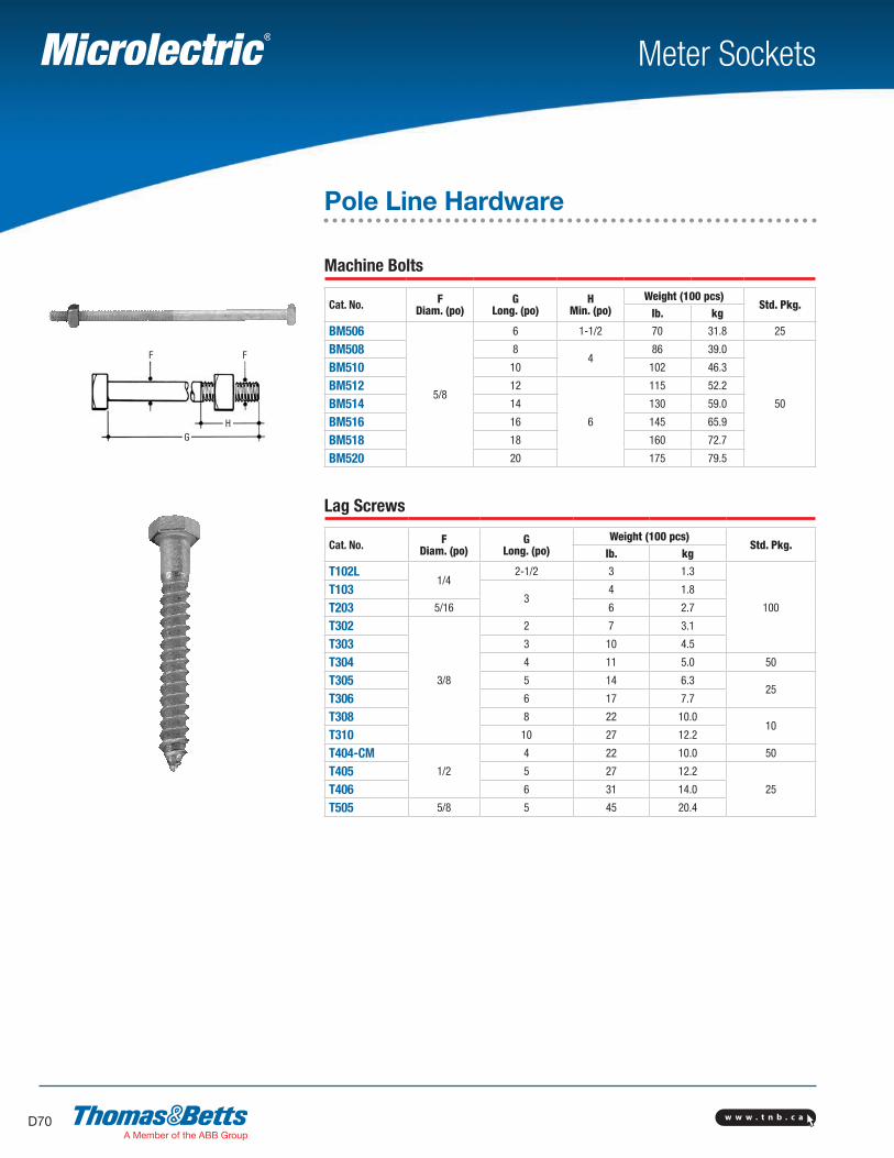
Machine Bolts
Cat. No. F Diam. (po)
GLong. (po)
HMin. (po)
Weight (100 pcs)Std. Pkg.
lb. kg
BM506
5/8
6 1-1/2 70 31.8 25
BM508 84
86 39.0
50
BM510 10 102 46.3
BM512 12
6
115 52.2
BM514 14 130 59.0
BM516 16 145 65.9
BM518 18 160 72.7
BM520 20 175 79.5
Lag Screws
Cat. No. F Diam. (po)
GLong. (po)
Weight (100 pcs)Std. Pkg.
lb. kg
T102L1/4
2-1/2 3 1.3
100
T1033
4 1.8
T203 5/16 6 2.7
T302
3/8
2 7 3.1
T303 3 10 4.5
T304 4 11 5.0 50
T305 5 14 6.325
T306 6 17 7.7
T308 8 22 10.010
T310 10 27 12.2
T404-CM1/2
4 22 10.0 50
T405 5 27 12.2
25T406 6 31 14.0
T505 5/8 5 45 20.4

w w w . t n b . c a D71
Meter Sockets
Pole Line Hardware
“U” Cable Guards and Straps
Cat. No. Width (in.)
Length(ft.) Size
Weight (100 pcs)Std. Pkg.
lb. kg
Straight
UG8114 1-1/4
8 –
760 345
5UG8214 2-1/4 1300 590
UG8314 3-1/4 2000 909
FlaredUGF8114 1-1/4
8 –
760 345
5UGF8214 2-1/4 1300 590
UGF8314 3-1/4 2000 909
StrapSUG114
– –
1-1/4 15 6.8
10SUG214 2-1/4 24 11.0
SUG314 3-1/4 60 27.0Hot dip galvanized 14 gauge steel. For nonmetallic version (PV-Mold™), refer to pp. D77-D81.
Guy Clamps
Cat. No.Bolt Length
(in.)Range(in.)
Weight (100 pcs)Std. Pkg
Qty. Size lb. kgGC902 2
1/23-1/4
1/4–7/16130 59.0 50
GC9043
5-7/8 224 101.325
GC906 5/8 6 5/16–1/2 274 124.5
Eye Nut
Cat. No. Eye Dimensions(in.)
Weight (100 pcs)Std. Pkg.
lb. kg
K58 1-5/16 x 1-11/16 70 31.8 50
Drop forged, hot galvanized, tapped 5/8 in.
2-7/16 in.
9/16 in.
1-5/16 in.
1-1/
4 in
.
1-1/4 in.
1-11
/16
in.
3-1/
2 in
.
W
L
w w w . t n b . c aD72
K133A
TS346
AR586 - AR347
EA08
Meter Sockets
Pole Line Hardware
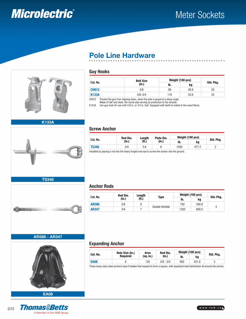
Guy Hooks
Cat. No. Bolt Size(in.)
Weight (100 pcs)Std. Pkg.
lb. kg
CH912 5/8 90 40.9 50
K133A 5/8–3/4 118 53.6 25CH912 Prevent the guy from slipping down, when the pole is guyed at a sharp angle. Made of half oval steel, the round side serving as protection to the strands.K133A Iron guy hook for use with 5/8 in. or 3/4 in. bolt. Equipped with teeth to imbed in the wood fibres.
Screw Anchor
Cat. No. Rod Dia.(in.)
Length(ft.)
Plate Dia.(in.)
Weight (100 pcs)Std. Pkg.
lb. kg
TS346 3/4 5.6 6 1050 477.2 2Installed by placing a rod into the heavy forged oval eye to screw the anchor into the ground.
Anchor Rods
Cat. No. Rod Dia.(in.)
Length(ft.) Type
Weight (100 pcs)Std. Pkg.
lb. kg
AR586 5/8 6Double thimble
750 340.95
AR347 3/4 7 1320 600.0
Expanding Anchor
Cat. No. Hole Size (in.)Required
Area(sq. in.)
Rod Dia. (in.)
Weight (100 pcs)Std. Pkg.
lb. kg
EA08 8 135 5/8 - 3/4 950 431.8 5These heavy duty steel anchors have 8 blades that expand to form a square, with equalized load distribution all around the anchor.

w w w . t n b . c a D73
Meter Sockets
Pole Line Hardware
Oval Eye Bolt
Cat. No. Description F Dia.(in.)
G Length (in.)
H Min.(in.)
Weight (100 pcs)Std. Pkg.
lb. kg
BO506
Oval eye bolt 5/8
6 3 122 55.4 50
BO508 8
4
136 61.8 25
BO510 10 150 68.1 25
BO512 12 168 76.3 25
Guy Strain Insulator
Cat. No. Length (ft.) Dia. (in.)Weight (100 pcs)
Std. Pkg.lb. kg
504WGS 4-1/4 2-7/81.0 0.45 1
506WGS 5-1/2 3-3/8
Guy Wire Guard
Cat. No. Colour Length (ft.)Weight (100 pcs)
Std. Pkg.lb. kg
2YG Yellow 6.7 3.35 1.46 10
Type W – Aluminum Service Wedge Clamps for use with ACSR, Aluminum, AAAC Conductors• For dead-ending self-supporting drop wire• Saves conductor – drop wire may be cut to exact length• Can be attached to bare neutral at any point in the span• Adjustments in drop wire sag are easily made• Grips ACSR, AAAC, or aluminum conductors
Cat. No.Conductor Range Dimensions (in.) Typical Tensile Values
ACSR AL AAAC D L Conductor Value (lb.)
W62-1 2–6 1 str. – 6 sol. 2–6 2-3/8 flex. 12, 17-1/2 2 6 x 1 ACSR 1200
W62-1FC 2–6 1 str. – 6 sol. 2–6 2-3/8 flex. 12, 17-1/2 2 6 x 1 ACSR 1200
W20-1 1/0–4 2/0 str. – 2 sol. 1/0–4 2-3/8 flex. 12-1/2, 18-1/2 1/0 6 x 1 ACSR 1800
W20-1FC 1/0–4 2/0 str. – 2 sol. 1/0–4 2-3/8 flex. 12-1/2, 18-1/2 1/0 6 x 1 ACSR 1800
W40-1* 4/0–2/0 4/0 str. – 2 sol. 4/0–2/0 2-3/8 flex. 12-3/4, 18-1/2 4/0 6 x 1 ACSR 1900
W40-1FC* 4/0–2/0 4/0 str. – 2 sol. 4/0–2/0 2-3/8 flex. 12-3/4, 18-1/2 4/0 6 x 1 ACSR 1900
* W40 series clamps rated 850 lb. ultimate tension for 1/0 ACSR, AL, or AAAC.
“FC” Flexible Bail(Bail Length – 11-1/2 in.)
Rigid Stainless Steel Bail(Bail Length – 6-1/2 in.
Note: Made of Porcelain
BO506-508-510-512
504WGS-506WGS
2YG
W-1 Series aluminum wedge and slider
G
H
L
W
D
L


