Download - Portable Solar Power Supply

Portable Solar Power Supply Group V:
David Carvajal Amos Nortilien Peter ObengNovember 20, 2012
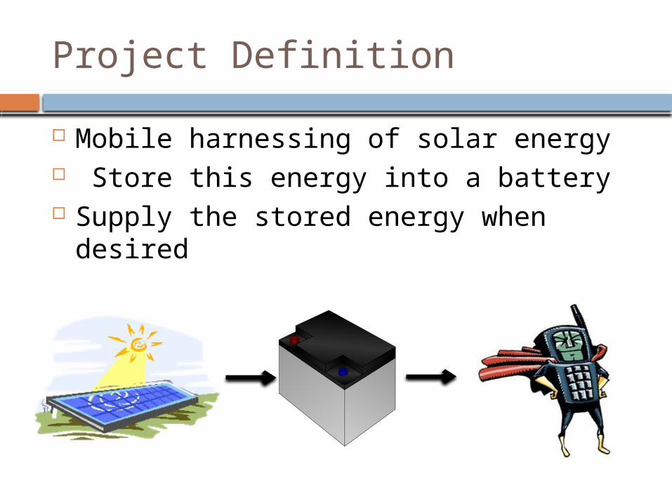
Project Definition Mobile harnessing of solar energy Store this energy into a battery Supply the stored energy when desired

Project Overview
Solar Panel Solar Tracking Maximum Power Point Tracking (MPPT) Charge Controller DC/DC Converter DC/AC Inverter

Goals and Objectives Harvest solar energy Convenient mobile power Lightweight Provide Power for broad range AC and
DC devices

Charge Regulator
Microcontroller (MPPT)
LCD Display
12 V Lead Acid Battery
Microcontroller and Motor (Solar
Tracking)Solar Panel Mount
Power from Solar Panel
Provision of AC and DC
Power
Portable Solar Power SupplyBlock Diagram
Specifications and Requirements
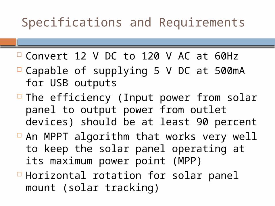
Convert 12 V DC to 120 V AC at 60Hz Capable of supplying 5 V DC at 500mA for
USB outputs The efficiency (Input power from solar panel
to output power from outlet devices) should be at least 90 percent
An MPPT algorithm that works very well to keep the solar panel operating at its maximum power point (MPP)
Horizontal rotation for solar panel mount (solar tracking)

Crystalline PV Panels Thin Film PV PanelsHigher Efficiency Low Priced High power per area Suited for large areas Ease of fabrication Better tolerance in the shadeHigh stability Less susceptible to damageHigher liability Flexible and easier to handle
Solar Panel Types
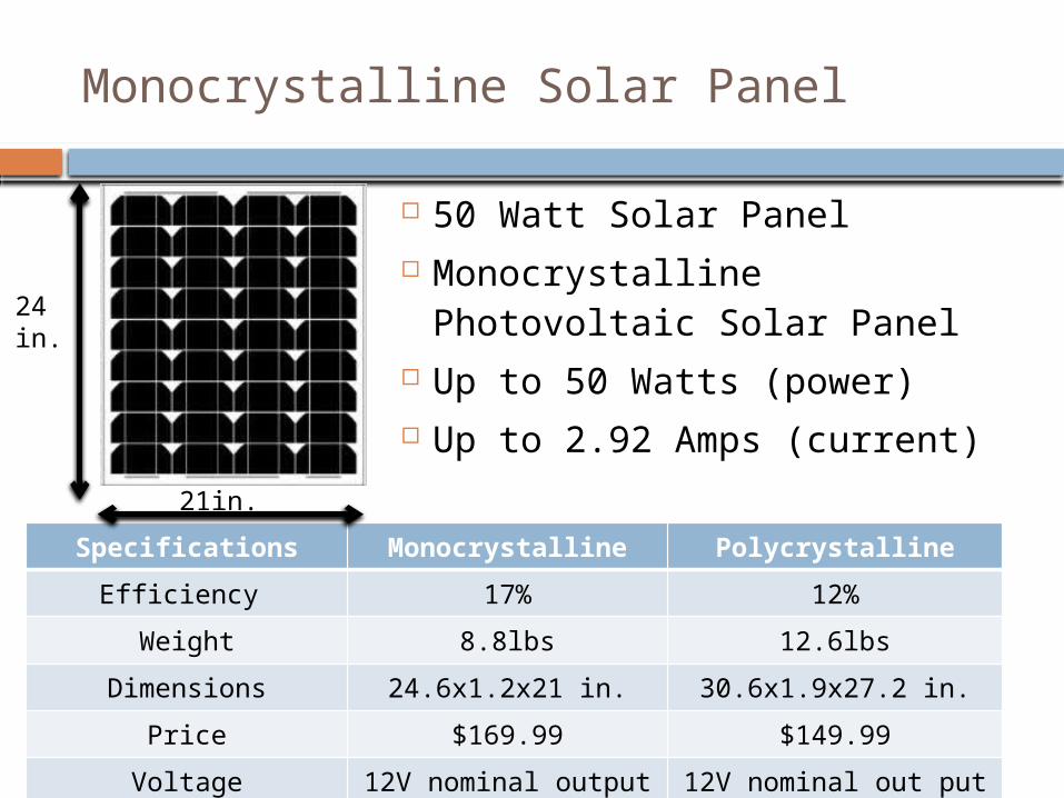
Specifications Monocrystalline PolycrystallineEfficiency 17% 12%
Weight 8.8lbs 12.6lbsDimensions 24.6x1.2x21 in. 30.6x1.9x27.2 in.
Price $169.99 $149.99Voltage 12V nominal output 12V nominal out put
Monocrystalline Solar Panel 50 Watt Solar Panel Monocrystalline
Photovoltaic Solar Panel Up to 50 Watts (power) Up to 2.92 Amps (current)
24 in.
21in.
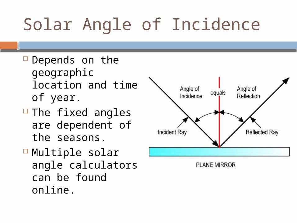
Solar Angle of Incidence Depends on the
geographic location and time of year.
The fixed angles are dependent of the seasons.
Multiple solar angle calculators can be found online.

Photoresistor The absolute maximum
temperature range for operating and storage of these photoresistors are -40 to +75 degrees Celsius.
The continuous power dissipation is 80mW and derate above 25 ˚C is 1.6mW/ ˚C.
The active surface of these photoresistors are plastic coated for protection.
These photoresistors have a maximum peak voltage of 100 volts.

Solar Tracker
Simple and Effective Design
2 photocells Arduino
Microcontroller Resistors Single Axis Tracker 4.8 – 6 V Servo Motor Solar panel mount Dimensions: 4.5
inches*6.625 inches

DC to DC Converter LT1776 Input Voltage from 7.4
V to 40V Outputs 5V, 500 mA 85% efficiency Switching frequency:
200kHz

DC to DC converter LT1676 Input Voltage
from 8V to 40V Outputs 5V, 500
mA 87% efficiency Switching
frequency: 100kHz

Battery
Manufacture: Battery Mart
Type: Sealed Lead Acid Battery
Voltage Output: 12 Volt Capacity: 35 Ah Size: 7.65 L x 5.25 w x 7.18 h
in. Cost : Donated Weight: 29.00 Pounds Battery Life: 100,000 hours
Deep Cycle Sealed Long Service Life Long Shelf Life Wide Operating
Temperature Ranges (-40°C to +60°C )
No Memory Effect Recyclable
Specification Convenience
Maximum Power Point Tracking (MPPT)
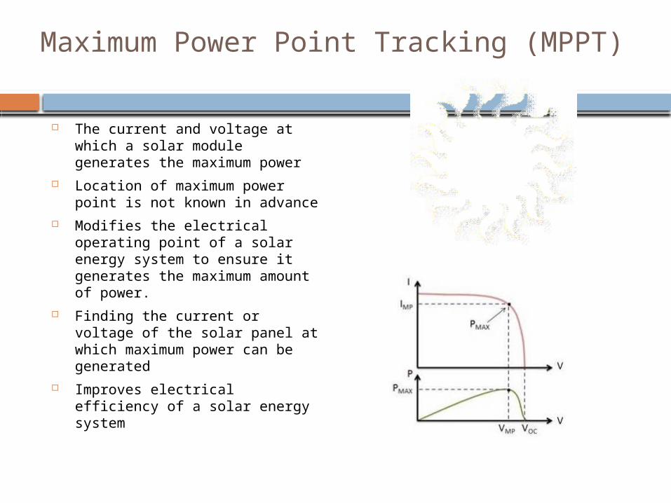
The current and voltage at which a solar module generates the maximum power
Location of maximum power point is not known in advance
Modifies the electrical operating point of a solar energy system to ensure it generates the maximum amount of power.
Finding the current or voltage of the solar panel at which maximum power can be generated
Improves electrical efficiency of a solar energy system

Maximum Power Point Tracking (MPPT)Algorithms
Perturb and Observe: Most commonly used because of its ease of implementation Modifies the operating voltage or current of the photovoltaic panel until
maximum power can be obtained
Incremental Conductance: Take advantage of the fact that the slope of the power-voltage curve is
zero at the maximum power point - The slope of the power voltage curve is positive at the left of the MPP and negative at the right of the MPP MPP is found by comparing the instantaneous conductance (I/V) to the
incremental conductance (ΔI/ΔV)
When MPP is obtained, the solar module maintains this power unless a change in ΔI occurs.

Maximum Power Point Tracking (MPPT)Algorithms
Increase the conversion ratio of the DC/DC/converter.
Measure the solar panel Watt. If the solar panel watts are greater than
the last measurement, then it is climbing the front of the hill, loop back and do it again.
Else if Watts are less than the last time measurement, then it is on the back side of the hill, decrease the conversion ratio and loop back to try again.

Charge Controller
DC/DC Converter (Buck)
Changes the solar panel’s higher voltage and lower current to the lower voltage and higher current needed to charge the battery.
Controlled by PWM signal that switches the MOSFETS at 50kHz
Prevents battery from discharging at night
Measures battery and solar panel’s voltage
Dimensions: 4.5 inches*6.625 inches
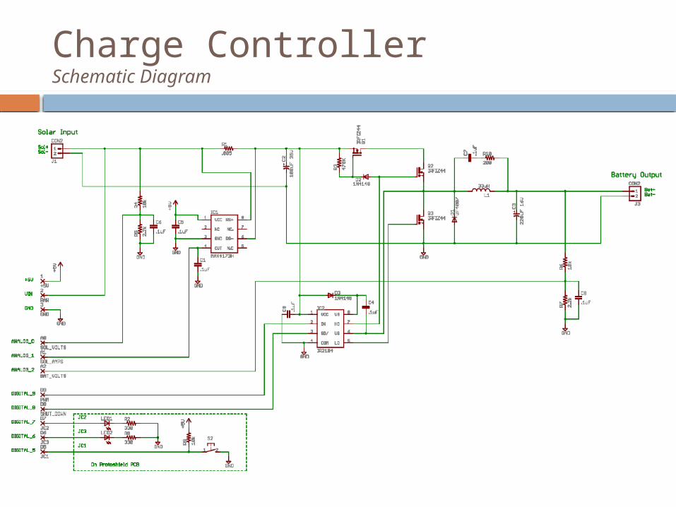
Charge ControllerSchematic Diagram

Charge ControllerCurrent Sense Resistor and High Side Current Sense Amplifier
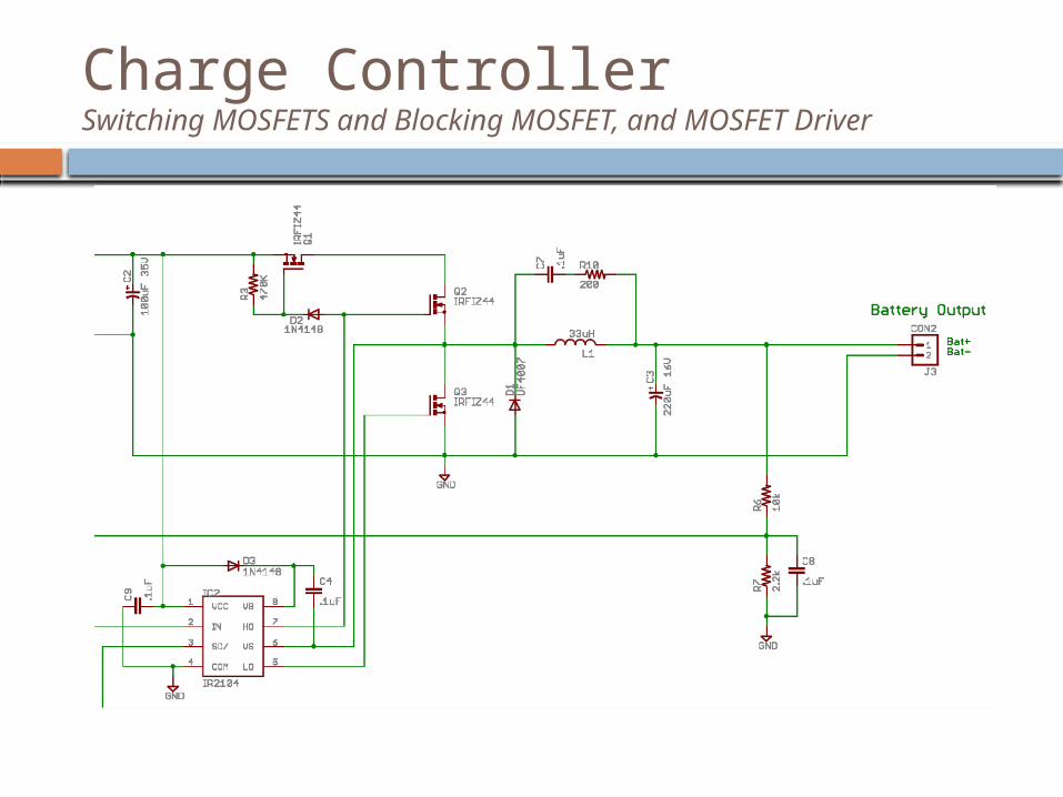
Charge ControllerSwitching MOSFETS and Blocking MOSFET, and MOSFET Driver

MicrocontrollerArduino Uno
Processor: ATmega328 Operating Voltage: 5 V Digital I/O Pins: 14 (6 provides
PWM output) Analog Input Pins: 6 DC Current per I/O Pin 40mA Flash Memory: 32KB (2KB is used
by bootloader) SRAM: 1 KB EEPROM: 512 bytes Clock Speed: 16MHz
Controls Charge Controller to Optimize battery charging
Displays status of the portable solar power supply on LCD display
Specification: Function:
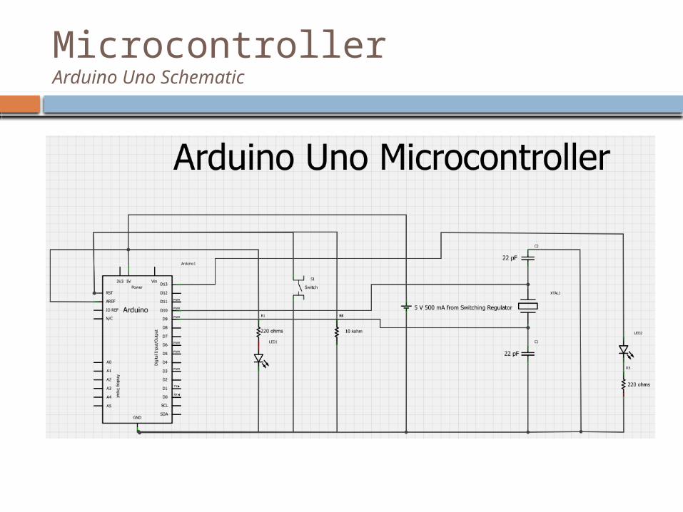
MicrocontrollerArduino Uno Schematic

LCD Display
Pin Symbol
Level Functions
1 VSS ---- GND (0V)2 VDD ---- Supply Voltage for Logic (+5V)3 V0 ---- Power supply for LCD4 RS H/L H: Data; L: instruction Code5 R/W H/L H: Read; L: Write6 E H/L Enable Signal7 DB0 H/L
Data Bus Line
8 DB1 H/L9 DB2 H/L10 DB3 H/L11 DB4 H/L12 DB5 H/L13 DB6 H/L14 DB7 H/L15 LEDA ---- Backlight Power (+5V)16 LEDB ---- Backlight Power (0V)
Pin connections

Pure sine wave InverterSpecifications
90% of Efficiency Output voltage of 120V AC at 60 Hz Power rating of 300 W

InverterInversion Process
Stepping up the low DC voltage to a much higher voltage using boost converter
Transforming the high DC voltage into AC signal using Pulse Width Modulation
Inversor=+
-u E
iS
u S
L +uMInverter

High Voltage DC/DC ConverterSpecification
Feed the high side of the H-bridge Efficiency of 90% Isolated voltage feedback Cooling passively

Block Diagram
Voltage Regulato
r
MCU Signal
Generation
H-bridge
AC Outpu
t Signal
MOSFETs
Drivers
DC Input
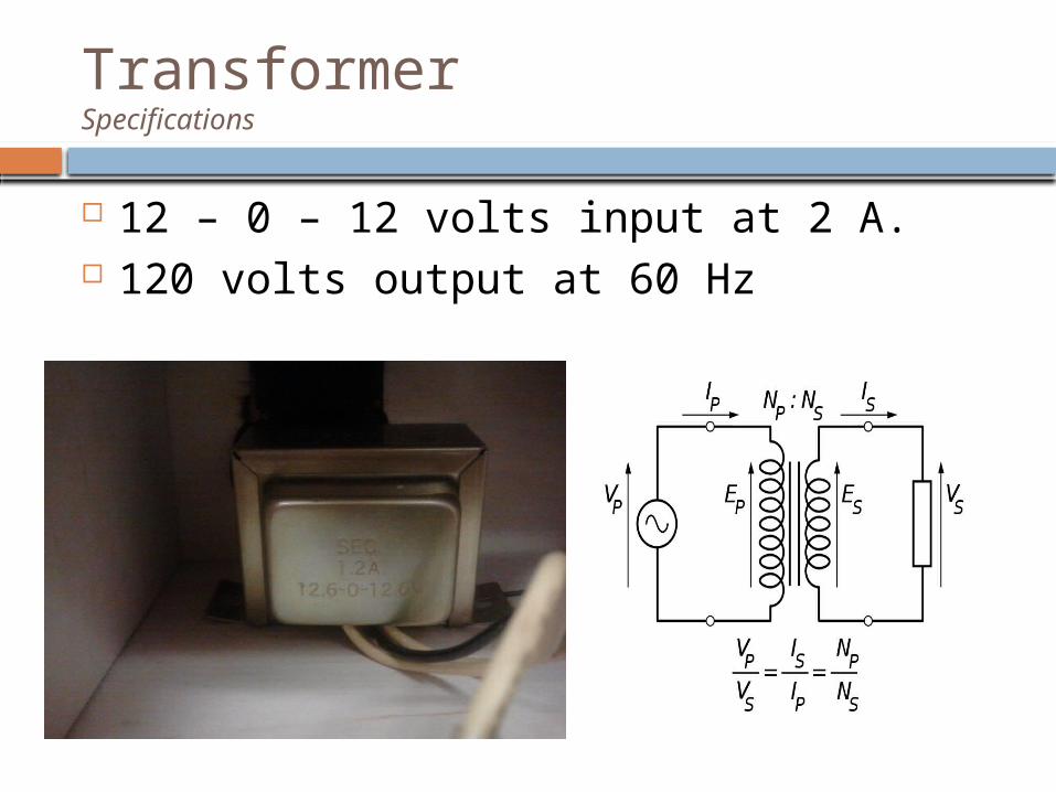
Transformer Specifications
12 – 0 – 12 volts input at 2 A. 120 volts output at 60 Hz

Pulse Width Modulation
Method of generating AC Power in Electronic Power Conversion through:1. Simple Analog Components2. Digital Microcontroller3. Specific PWM Integrated Circuits

Pulse Width Modulation2 Level PWM Signal
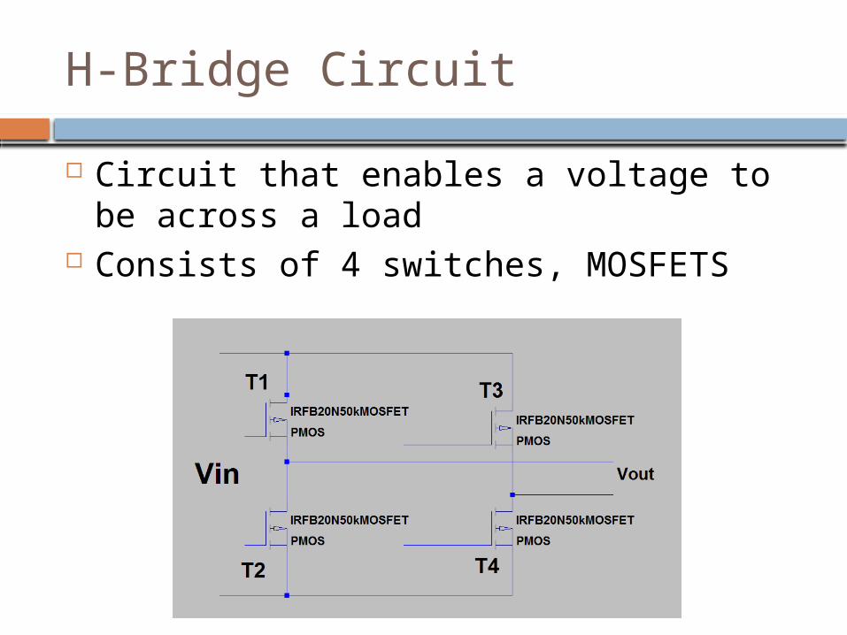
H-Bridge Circuit Circuit that enables a voltage to be
across a load Consists of 4 switches, MOSFETS

H-Bridge CircuitControl of the Switches
High side left
High side right
Low side left
Low side right
Voltage load
On Off Off On Positive
Off On On Off Negative
On On Off Off Zero
Off Off On On Zero
Table 4.4.4-1: Switches Position and Load Sign
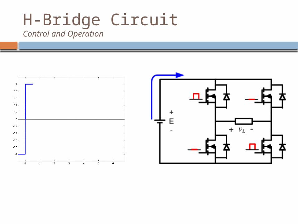
H-Bridge CircuitControl and Operation
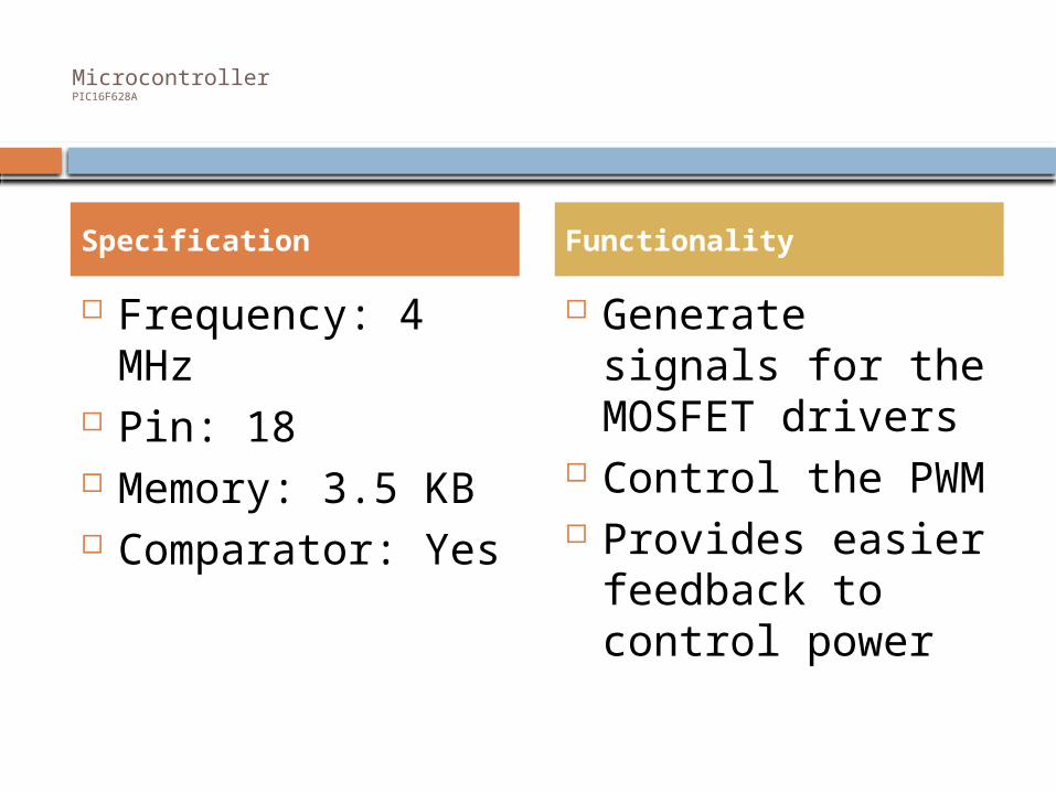
MicrocontrollerPIC16F628A
Frequency: 4 MHz Pin: 18 Memory: 3.5 KB Comparator: Yes
Generate signals for the MOSFET drivers
Control the PWM Provides easier
feedback to control power
Specification Functionality
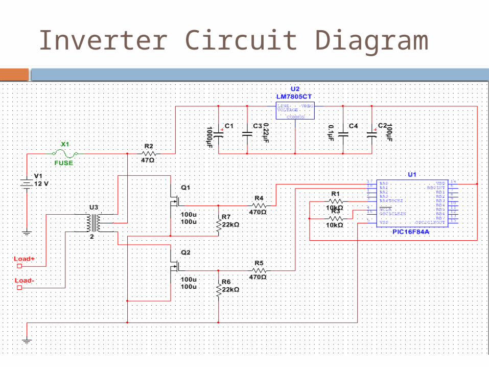
Inverter Circuit Diagram

Inverter

Testing MPPTPower Supply Electronic DC Load
18.4 2.19 14 2.71
16 2.52 13.9 2.71
14 1.66 7.9 2.71
12 1.65 6.4 2.791
17.25 2.25 13 2.791
18.75 2.1 12.8 2.971
Power 40.296 37.94 94.15%
40.32 37.669 93.43%
23.24 21.409 92.12%
19.8 17.8624 90.21%
38.8125 36.283 93.48%
39.375 38.0288 96.58%
MPPT Average 93.33%

Progress
Solar MountDC/DC
Solar TrackerLCD Screen
MSP430Charge Controller
ArduinoAC/DC Inverter
0.00% 50.00% 100.00%
Progress
Progress

Budget
Servo
Moto
r
Solar
Pane
l
LT167
6
LT177
6
Batte
ry
ProtoB
oards
DC USB Outp
uts
Solar
Track
er
Solar
Mou
nt
AC Outp
ut
LCD Sc
reen
Arduin
o ATM
EGA 3
28
Charge
Contro
ller
$0.00
$40.00
$80.00
$120.00
$160.00
BudgetSpent

Total Spent
$500.00

Questions??


