Gas Well Deliquification WorkshopSheraton Hotel, Denver, Colorado
February 22 - 24, 2010
FLATpaktm UmbilicalPresented By Collin Morris – President & Chief Technology Officer
CJS Coiled Tubing Supply Ltd. – Lloydminster, Alberta, Canada

Feb. 22 - 24, 2010 2010 Gas Well Deliquification WorkshopDenver, Colorado 2
Agenda
Heading
• What is the Vertical Umbilical
• Why was the Vertical Umbilical developed
• Advantages of using the Vertical Umbilical
• What are the components of the Vertical Umbilical
• How is Vertical Umbilical manufactured
• Original challenges
• Alternative applications for the Vertical Umbilical
• Where is the Vertical Umbilical being utilized and how
• Technical challenges/solutions

Feb. 22 - 24, 2010 2010 Gas Well Deliquification WorkshopDenver, Colorado
3
Definition of the System
The Vertical Umbilical is a uniquely designed multiple conduit bundlethat:
•Was originally designed for CONVEYING hydraulic subsurface pumps•Provides a hydraulic circuit for POWERING these pumps•Provides a PRODUCTION CONDUIT for producing the well•Is installed by conventional coiled tubing units•Utilizes complete Canadian class 1+2 “safe operating” practices•Used for deployment of subsurface hydraulic pumps, electricsubmersible pumps, gas lift & other artificial lift systems

Feb. 22 - 24, 2010 2010 Gas Well Deliquification WorkshopDenver, Colorado
4
Why Was the Vertical Umbilical DevelopedWhy Was the Vertical Umbilical Developed
The Vertical Umbilical was developed to …
• Efficiently & safely convey hydraulic based pumps• Replace jointed production tubing and rods• Eliminate the “Conventional Rig” for installation• Combine multiple services into one & reduce surface
footprint• Provide flexibility in design and function• Permit temporary intervention with Artificial Lift Systems

Feb. 22 - 24, 2010 2010 Gas Well Deliquification WorkshopDenver, Colorado 5
Material SpecificationsMaterial Specifications
• Carbon Steel Coiled Tubing• High Strength 70/80k Grade, various gauges• High Tensile Strength• Outstanding low cycle fatigue• Well understood mechanical and chemical properties• External FBE Coatings enable use in mild H2S/CO2
environments for closed hydraulic systems
• Alternative Tubular Materials
• 304 SS, 316-L SS
• Lean Duplex Alloy 19D
• Alternative “hi temp” acid resistant thermo plastic tubefor low pressure, shallow applications

Feb. 22 - 24, 2010 2010 Gas Well Deliquification WorkshopDenver, Colorado 6
Encapsulation SpecificationsEncapsulation Specifications
• Encapsulation Material
• Vulcanized Thermoplastic (PP/EPDM)
• Temperature Rating-135C
• Chemical Resistance to all Oilfield Solvents andchemicals
• Excellent Abrasion Resistance (Taber Test) ASTM D904Wear Index 5
• Has been used for “eons” for capillary tubing protectionand SCSSV installations

Feb. 22 - 24, 2010 2010 Gas Well Deliquification WorkshopDenver, Colorado 7
Pressurized Extrusion ProcessPressurized Extrusion Process

Feb. 22 - 24, 2010 2010 Gas Well Deliquification WorkshopDenver, Colorado 8
Dimensions for HSP UmbilicalDimensions for HSP UmbilicalDescription Dimensions Weight lbs/ ft
1” x ¾” x 1” 3.051” x 1.20” 2.69
1” x 5/8” x 1” 2.925” x 1.20” 2.88
1” x 1” x 1” 3.300” x 1.20” 2.71
¾” x ¾” x ¾” 2.80” x .95” 2.12
Cross Section Umbilical Configuration

Feb. 22 - 24, 2010 2010 Gas Well Deliquification WorkshopDenver, Colorado 9
Original Challenges to OvercomeOriginal Challenges to Overcome• The Vertical Umbilical could be
spooled in its configuration
• “Encapsulation” material couldwithstand stresses of spooling
• “Encapsulation” equipment couldhandle the tubing sizes
• Chains/Gripper Blocks couldfunction without damage
• Well Control equipmentmodifications could be made
• Conventional CT wellhead couldbe modified to support the system

Feb. 22 - 24, 2010 2010 Gas Well Deliquification WorkshopDenver, Colorado 10
Application Types/SystemsApplication Types/Systems
HSP Pump3-Line System
Single Point2-Line Gas Lift
orJet Pump
ESP Pump1 Line + Cable
Current LiftTypes/Suppliers
•HSP Activator-GlobalEnergy
•HSP Perry Pump-Cyclone
•HSP Hygr Pump-HydroPacfic
•HSP Cormorant Pump
•Jet Pump(JetPakTM)-Source Rock

Feb. 22 - 24, 2010 2010 Gas Well Deliquification WorkshopDenver, Colorado 11
Application Types/SystemsApplication Types/Systems (Con(Con’’t)t)
HSP Pump3-Line System
Single Point2-Line Gas Lift
orJet Pump
ESP Pump1 Line + Cable
Systems underdevelopment
•ESP Permanent
•Hydraulic Centrifugal
•Hydraulic PCP
•HSP Dual Stroke
•Multi Pt. Gas Lift

Feb. 22 - 24, 2010 2010 Gas Well Deliquification WorkshopDenver, Colorado 12
Other Additional CapabilitiesOther Additional Capabilities
• Downhole Chemical Injection
• Downhole Reservoir DataAcquisition
• Downhole Optical Fiber DataTransmission
• Downhole Camera Conveyance

Feb. 22 - 24, 2010 2010 Gas Well Deliquification WorkshopDenver, Colorado 13
Application HistoryApplication History
•Canada - multiple 3200 ft hydraulic pump installations•Canada - multiple 3500 ft jet pump installations•Canada - multiple 2500 ft vertical well HSP and Jet Pump cleanouts•Oklahoma - multiple 4500 ft horizontal well Jet Pump cleanouts•Oklahoma - multiple 3000 ft hydraulic pump installations•Texas - multiple 7000 ft Barnett & Fayetteville shale HSP installations•Montana 5600 ft single point gas lift and chemical injection

Feb. 22 - 24, 2010 2010 Gas Well Deliquification WorkshopDenver, Colorado 14
HSP CleanoutsHSP Cleanouts• 3-Line HSP service pump for CBM
wells in Alberta - total 100+ wellsserviced
• 1-Line provides production conduitfor produced water to surface frompump discharge
• 2-Lines provide closed-loop hydrauliccircuit
• Use of this system reduces fluids andpressure placed on reservoir duringoperation for cleanout
• Results in a non-invasive treatment
• Ideal means to test HSP
• Cost effective/no CAPEX

Feb. 22 - 24, 2010 2010 Gas Well Deliquification WorkshopDenver, Colorado 15
Jet Pump CleanoutsJet Pump Cleanouts
UmbilicalTubingSystem
ProductionMode
Jetting Mode
• JetPakTM service with2-line FlatPak string &modified jet pump
• for dewatering & fillremoval operations inCBM and conventionalgas wells
• 1 line for jet pumppower fluid / 1 line forreturn fluids
• 150 wells serviced infirst 6 months ofoperation in Canada
• Successful 10 horizontalCBM well pilot project inOklahoma
Feb. 22 - 24, 2010 2010 Gas Well Deliquification WorkshopDenver, Colorado 16
Jet Pump CleanoutsJet Pump Cleanouts (Cont.)(Cont.)
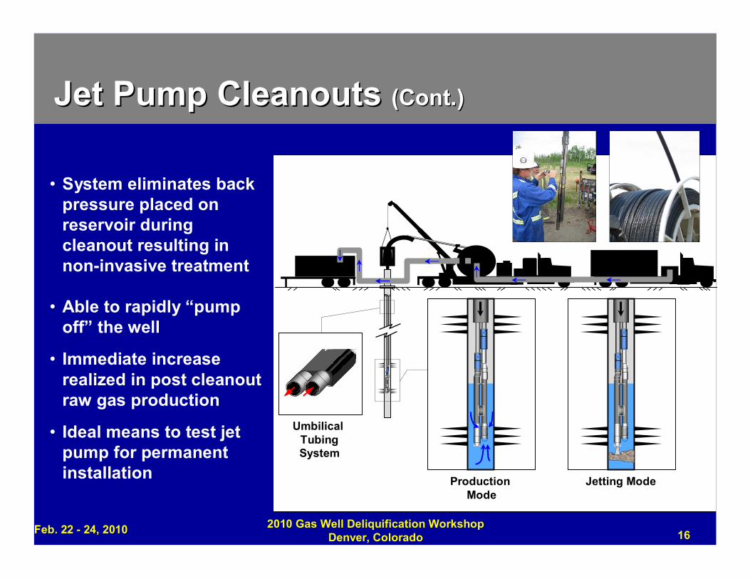
• System eliminates backpressure placed onreservoir duringcleanout resulting innon-invasive treatment
• Able to rapidly “pumpoff” the well
• Immediate increaserealized in post cleanoutraw gas production
• Ideal means to test jetpump for permanentinstallation
UmbilicalTubingSystem
ProductionMode
Jetting Mode
0.00
Vo
lum
e(m
3)
02/01/200903/05/2009
04/06/200905/08/2009
06/09/200907/11/2009
08/12/200909/13/2009
10/15/2009
Date
Jet Pump CleanoutsJet Pump Cleanouts (Cont.)(Cont.)
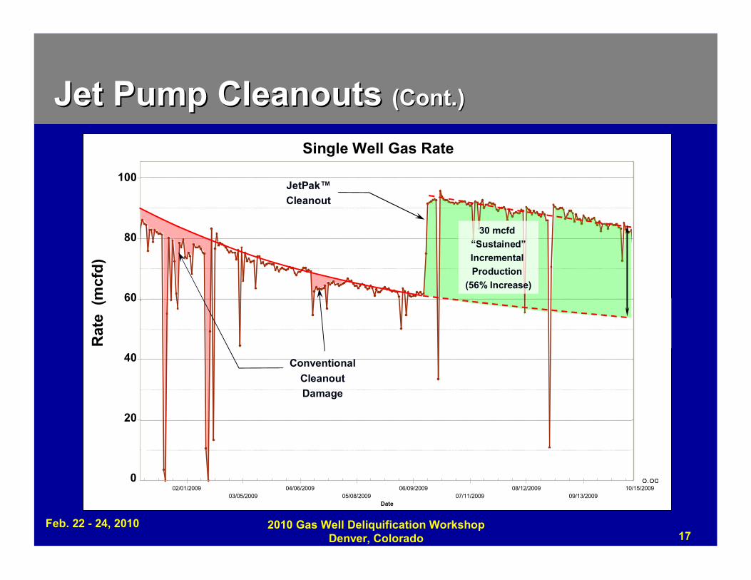
Single Well Gas Rate
Rat
e(m
cfd
)
100
80
60
40
20
Feb. 22 - 24, 2010 2010 Gas Well Deliquification WorkshopDenver, Colorado 17
0
ConventionalCleanoutDamage
JetPak™Cleanout
30 mcfd“Sustained”IncrementalProduction
(56% Increase)

Jet Pump CleanoutsJet Pump Cleanouts (Cont.)(Cont.)
Clean-out Volume (m3) Raw Gas Gross (mcf/day)
0.00
200.00
400.00
600.00
800.00
1,000.00
0.00
0.80
1.60
2.40
3.20
4.00
02/01/200903/05/2009
04/06/200905/08/2009
06/09/200907/11/2009
08/12/200909/13/2009
10/15/2009
Date
Gas Rate Only9 Completions
Oct 16, 2009, 15:04
9 WellJetPak™CleanoutCampaign
100 mcfd Incremental Production(18% increase)
Gas Rate - Group
Rat
e(m
cfd
)
1,000
800
600
400
200
Clean
ou
tVolum
e(m
3)
4.0
3.2
2.4
1.6
0.8
Feb. 22 - 24, 2010 2010 Gas Well Deliquification WorkshopDenver, Colorado 18
0 0.0

Feb. 22 - 24, 2010 2010 Gas Well Deliquification WorkshopDenver, Colorado 19
Technical Issues/SolutionsTechnical Issues/Solutions
• Gas migration / explosive decompression entering downhole“encapsulation end”
• Depth limitations related to potential damage to encapsulationby CT Injector Head Gripper Blocs
• Wellhead Modifications
• Temperature and application compatibility
• Fishing

Feb. 22 - 24, 2010 2010 Gas Well Deliquification WorkshopDenver, Colorado 20
Technical Issues/SolutionsTechnical Issues/Solutions
SOLUTION…Gas Migration /Explosive Decompression
• Addition of “underlayer” ofPolyethylene Polymer from Innotek“G-55”
• Field trials prove advantageous byimproving adhesion of tube toencapsulation

Feb. 22 - 24, 2010 2010 Gas Well Deliquification WorkshopDenver, Colorado 21
Technical Issues/SolutionsTechnical Issues/Solutions
SOLUTION… Depth limitationsrelated to potential damage toencapsulation by CT InjectorHead
•Increased surface area results indecreased “skate” hydraulic pressure
•Newly designed “drive arch” systemresults in increased surface area anddecreased “skate” pressure resultingin ability to “run deeper” with outpotential damage to encapsulation

Feb. 22 - 24, 2010 2010 Gas Well Deliquification WorkshopDenver, Colorado 22
Technical Issues/SolutionsTechnical Issues/Solutions
SOLUTION… WellheadModifications
•To prevent Umbilical slippagethrough Dognut when using hardercoiled tubing, newly designed dognutslips in the form of conventionalwellhead slips are being designed

Feb. 22 - 24, 2010 2010 Gas Well Deliquification WorkshopDenver, Colorado 23
Technical Issues/SolutionsTechnical Issues/Solutions
SOLUTION… Temperature andapplication versatility
Santoprene or Nexoprene TPVproves to work very well in numerousfield trials when subjected long termunder pressure, temperature andvarious hydrocarbon exposures
To achieve greater versatility inapplication, research is beingconducted to identify additionalthermoplastic elastomers for new,higher temperature and pressureapplications and address potentialhydrocarbon permeation

Feb. 22 - 24, 2010 2010 Gas Well Deliquification WorkshopDenver, Colorado 24
Technical Issues/SolutionsTechnical Issues/Solutions
SOLUTION… Fishing
•In the event of downhole umbilicalloss, fishing tools have beendesigned and successfully tested torecover FlatPak with a conventionalservice rig

Feb. 22 - 24, 2010 2010 Gas Well Deliquification WorkshopDenver, Colorado 25
Advantages of Vertical UmbilicalAdvantages of Vertical UmbilicalSuperior Design
• Minimizes formation damage due to live well intervention• Provides mechanical and corrosion protection and insulation
from extreme temperatures• Easily repaired in the field• Optional selections of tubing or wire proven they can be
spooled
Versatility• Facilitates permanent pump installation and temporary
service intervention• Configuration can be easily altered for specific applications• Is conveyed with any conventional CT unit

Feb. 22 - 24, 2010 2010 Gas Well Deliquification WorkshopDenver, Colorado 26
Advantages of Vertical UmbilicalAdvantages of Vertical Umbilical (Con(Con’’t)t)
Efficiency• Permits intervention consolidation (ie: Coiled tubing unit replaces
service rigs, capillary rigs & cable spool rigs)• Facilitates swift and efficient operations in a CT environment with
minimal surface disturbance
Safety• Offers multiple points of well control

Feb. 22 - 24, 2010 2010 Gas Well Deliquification WorkshopDenver, Colorado
27
Copyright
Rights to this presentation are owned by the company(ies) and/orauthor(s) listed on the title page. By submitting this presentation tothe Gas Well Deliquification Workshop, they grant to the Workshop,the Artificial Lift Research and Development Council (ALRDC), andthe Southwestern Petroleum Short Course (SWPSC), rights to:
– Display the presentation at the Workshop.
– Place it on the www.alrdc.com web site, with access to the site to beas directed by the Workshop Steering Committee.
– Place it on a CD for distribution and/or sale as directed by theWorkshop Steering Committee.
Other use of this presentation is prohibited without the expressedwritten permission of the author(s). The owner company(ies) and/orauthor(s) may publish this material in other journals or magazines ifthey refer to the Gas Well Deliquification Workshop where it wasfirst presented.

Feb. 22 -24, 2010 2010 Gas Well Deliquification WorkshopDenver, Colorado
28
DisclaimerThe following disclaimer shall be included as the last page of a Technical Presentation orContinuing Education Course. A similar disclaimer is included on the front page of the Gas WellDeliquification Web Site.
The Artificial Lift Research and Development Council and its officers and trustees, and the GasWell Deliquification Workshop Steering Committee members, and their supporting organizationsand companies (here-in-after referred to as the Sponsoring Organizations), and the author(s) ofthis Technical Presentation or Continuing Education Training Course and their company(ies),provide this presentation and/or training material at the Gas Well Deliquification Workshop "as is"without any warranty of any kind, express or implied, as to the accuracy of the information or theproducts or services referred to by any presenter (in so far as such warranties may be excludedunder any relevant law) and these members and their companies will not be liable for unlawfulactions and any losses or damage that may result from use of any presentation as a consequenceof any inaccuracies in, or any omission from, the information which therein may be contained.
The views, opinions, and conclusions expressed in these presentations and/or training materialsare those of the author and not necessarily those of the Sponsoring Organizations. The author issolely responsible for the content of the materials.
The Sponsoring Organizations cannot and do not warrant the accuracy of these documentsbeyond the source documents, although we do make every attempt to work from authoritativesources. The Sponsoring Organizations provide these presentations and/or training materials asa service. The Sponsoring Organizations make no representations or warranties, express orimplied, with respect to the presentations and/or training materials, or any part thereof, includingany warrantees of title, non-infringement of copyright or patent rights of others, merchantability, orfitness or suitability for any purpose.


![flatpak catalog new lang - fabprefab CAT1... · cork bamboo FLOR carpet light black ... [Charlie’s house under assembly] ... flatpak catalog new lang.indd](https://cdn.vdocument.in/doc/165x107/5aaaf7b27f8b9aa9488b629f/flatpak-catalog-new-lang-cat1cork-bamboo-flor-carpet-light-black-charlies.jpg)