
TSPIOX-S721V2-1-2EN_Leu, 2017-04-28
Technical specification
PIOX® S721
1
PIOX
PIOX
Variofix C
S721**-****A
S721**-****S
Process analysis and flow measurement with ultrasound
Clamp-on ultrasonic measuring system for continuous non-invasive monitoring of concentration, density orother process-relevant fluid properties
Features
• Non-invasive transit time measurement for the determi-nation of concentration, density and density-related physical quantities
• Simultaneous bidirectional, highly dynamic flow mea-surement
• No fluid contact, no need of special materials
• Ideal for aggressive, toxic or abrasive fluids
• Maintenance-free and drift-free measurement
Applications• Chemical industry
• Petrochemical industry
• Oil and gas industry
• Pharmaceutical industry
• Semiconductor industry
• Mechanical and electrical engineering
• Food industry

PIOX® S721 Technical specification
Table of contents
TSPIOX-S721V2-1-2EN_Leu, 2017-04-282
Function ........................................................................................................................................................... 3Measurement principle...................................................................................................................................... 3Transit time measurement ................................................................................................................................ 3Transit time difference principle ........................................................................................................................ 4Number of sound paths..................................................................................................................................... 5
Transmitter ...................................................................................................................................................... 6Technical data................................................................................................................................................... 6Dimensions ....................................................................................................................................................... 92 " pipe mounting kit (optional)........................................................................................................................ 10Terminal assignment....................................................................................................................................... 11
Transducers................................................................................................................................................... 12Transducer selection....................................................................................................................................... 12Transducer order code.................................................................................................................................... 13Technical data................................................................................................................................................. 14Transducer mounting fixture ........................................................................................................................... 23
Coupling materials for transducers ............................................................................................................ 25
Connection systems ..................................................................................................................................... 26Transducer cable ............................................................................................................................................ 27
Junction box .................................................................................................................................................. 28Technical data................................................................................................................................................. 28Dimensions ..................................................................................................................................................... 282 " pipe mounting kit (optional)........................................................................................................................ 29Terminal assignment....................................................................................................................................... 29
Clamp-on temperature probe (optional) ..................................................................................................... 31
Technical specification PIOX® S721
TSPIOX-S721V2-1-2EN_Leu, 2017-04-28 3
Function
Measurement principle
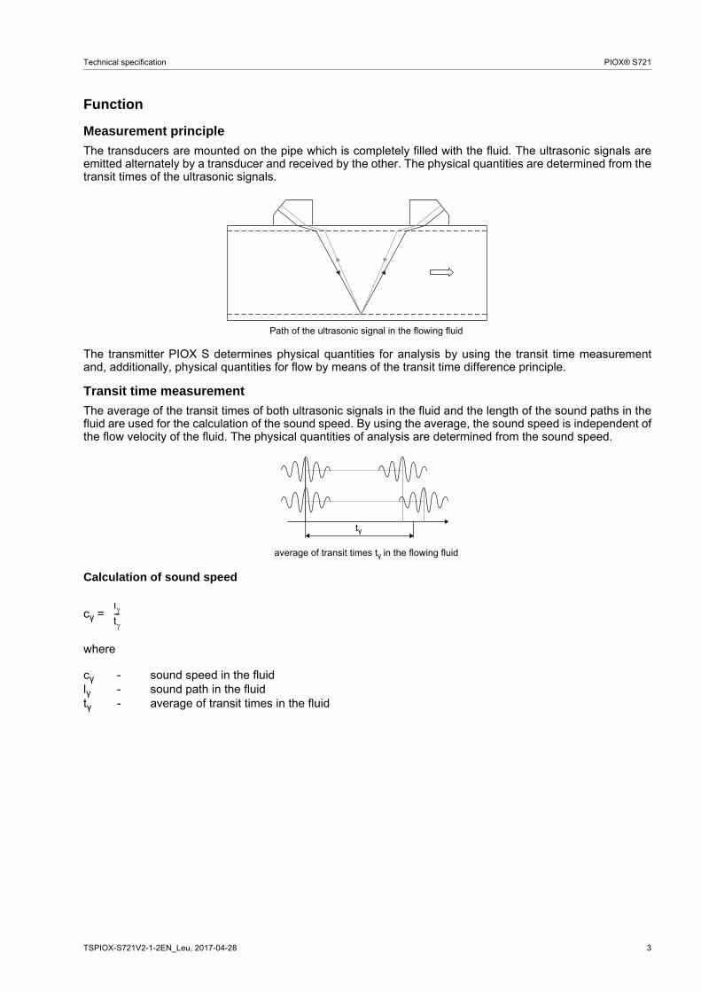
The transducers are mounted on the pipe which is completely filled with the fluid. The ultrasonic signals areemitted alternately by a transducer and received by the other. The physical quantities are determined from thetransit times of the ultrasonic signals.
The transmitter PIOX S determines physical quantities for analysis by using the transit time measurementand, additionally, physical quantities for flow by means of the transit time difference principle.
Transit time measurement
The average of the transit times of both ultrasonic signals in the fluid and the length of the sound paths in thefluid are used for the calculation of the sound speed. By using the average, the sound speed is independent ofthe flow velocity of the fluid. The physical quantities of analysis are determined from the sound speed.
Calculation of sound speed
cγ =
where
Path of the ultrasonic signal in the flowing fluid
average of transit times tγ in the flowing fluid
cγ - sound speed in the fluidlγ - sound path in the fluidtγ - average of transit times in the fluid
tγ
lt---

4 TSPIOX-S721V2-1-2EN_Leu, 2017-04-28
PIOX® S721 Technical specification
Transit time difference principle
Die Laufzeit des Ultraschallsignals in Flussrichtung ist kürzer als entgegen der Flussrichtung, da das Fluid, indem sich der Ultraschall ausbreitet, fließt.
The transit time difference, ∆t, is measured and allows the flowmeter to determine the average flow velocityalong the propagation path of the ultrasonic signals. A flow profile correction is then performed in order to ob-tain the area averaged flow velocity, which is proportional to the volumetric flow rate.
Two integrated microprocessors control the entire measuring process. This allows the flowmeter to removedisturbance signals, and to check each received ultrasonic wave for its validity which reduces noise.
Calculation of volumetric flow rate
= kRe · A · ka ·
where
Transit time difference ∆t
- volumetric flow ratekRe - fluid mechanics calibration factorA - cross-sectional pipe areaka - acoustical calibration factor∆t - transit time differencetγ - average of transit times in the fluid
∆tt0
V· t2 t-----------
V·

Technical specification PIOX® S721
TSPIOX-S721V2-1-2EN_Leu, 2017-04-28 5
Number of sound paths
The number of sound paths is the number of transits of the ultrasonic signal through the fluid in the pipe. De-pending on the number of sound paths, the following methods of installation exist:
• reflection arrangementThe number of sound paths is even. Both of the transducers are mounted on the same side of the pipe. Correct positioning of the transducers is easier.
• diagonal arrangementThe number of sound paths is odd. Both of the transducers are mounted on opposite sides of the pipe. In the case of a high signal attenuation by the fluid, pipe and coatings, diagonal arrangement with 1 sound path will be used.
The preferred method of installation depends on the application. While increasing the number of sound pathsincreases the accuracy of the measurement, signal attenuation increases as well. The optimum number ofsound paths for the parameters of the application will be determined automatically by the transmitter.
As the transducers can be mounted with the transducer mounting fixture in reflection arrangement or diagonalarrangement, the number of sound paths can be adjusted optimally for the application..
a - transducer distance
Reflection arrangement, number of sound paths: 2
Diagonal arrangement, number of sound paths: 3
Diagonal arrangement, number of sound paths: 1 Diagonal arrangement, number of sound paths: 1,negative transducer distance
a
a
a > 0 a < 0

6 TSPIOX-S721V2-1-2EN_Leu, 2017-04-28
PIOX® S721 Technical specification
Transmitter
Technical data
PIOX S721**-NN0*A S721**-NN0*SS721**-A20*S
order code TF7-S721**-****A*-*******-*****-** TF7-S721**-****S*-*******-*****-**TF7-S721**-****B*-*******-*****-**
design standard field device field devicewith stainless steel housing
analysismeasurement uncertainty
- transit time (repeatable) 1/(50 . fα) ± 10-4 . t
- transit time (absolute) 1/(5 . fα) ± 10-4 . t
fα - transducer frequency, t - total transit time
e.g. for transducers with transducer frequency M (fα = 1 MHz):repeatable: 20 ns ± 10-4 . t, absolute: 200 ns ± 10-4 . t
The total measurement uncertainty of a physical quantity for analysis is supplied order-related as it depends on the fluid, operating range and installation. For the basis of calculation see document TIPIOX-S_uncert_analysis.
flowmeasurement principle transit time difference correlation principleflow velocity 0.01...25 m/srepeatability 0.15 % of reading ±0.01 m/s
accuracy1
- with standard calibration ±1.6 % of reading ±0.01 m/s- with advanced calibration
(optional)±1.2 % of reading ±0.01 m/s
- with field calibration2 ±0.5 % of reading ±0.01 m/sfluid all acoustically conductive liquids with < 10 % gaseous or solid content in volumetemperature compensation corresponding to the recommendations in ANSI/ASME MFC-5.1-2011transmitterpower supply 100...230 V/50...60 Hz or
20...32 V DC or11...16 V DC
power consumption < 15 Wnumber of measuring chan-nels
1, optional: 2
damping 0...100 s, adjustablemeasuring cycle (1 channel) 100...1000 Hzresponse time 1 s (1 channel)housing material aluminum, powder coated stainless steel 316L (1.4404)degree of protection accord-ing to IEC/EN 60529
IP66 IP66
dimensions see dimensional drawingweight 5.4 kg 5.1 kgfixation wall mounting, optional: 2 " pipe mountingambient temperature -40...+60 °C (< -20 °C without operation of the display)display 128 x 64 dots, backlightmenu language English, German, French, Dutch, Spanish, Russian, Polishexplosion protection
ATEX/IECEx
transmitter - S721**-A20*Szone - 2marking -
Ex nA nC ic IIC T4 GcEx tb IIIC T 120 °C DbTa -40...+60 °C
certification ATEX - IBExU11ATEX1015certification IECEx - IECEx IBE 11.0008type of protection - gas: non sparking
dust: protection by enclosure1 for reference conditions and v > 0.15 m/s2 reference uncertainty < 0.2 %
II3GII2D
0637
Technical specification PIOX® S721
TSPIOX-S721V2-1-2EN_Leu, 2017-04-28 7
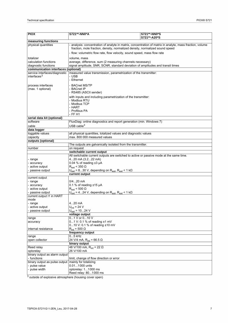
measuring functionsphysical quantities - analysis: concentration of analyte in matrix, concentration of matrix in analyte, mass fraction, volume
fraction, mole fraction, density, normalized density, normalized sound speed
- flow: volumetric flow rate, flow velocity, sound speed, mass flow rate
totalizer volume, masscalculation functions average, difference, sum (2 measuring channels necessary)diagnostic functions signal amplitude, SNR, SCNR, standard deviation of amplitudes and transit timescommunication interfaces (optional)service interfaces/diagnostic interfaces
measured value transmission, parametrization of the transmitter:- USB- Ethernet
process interfaces(max. 1 optional)
- BACnet MS/TP- BACnet IP- RS485 (ASCII sender)
with inputs and including parametrization of the transmitter:- Modbus RTU- Modbus TCP- HART- Profibus PA- FF H1
serial data kit (optional)software FluxDiag: online diagnostics and report generation (min. Windows 7)
сable USB cable3
data loggerloggable values all physical quantities, totalized values and diagnostic valuescapacity max. 800 000 measured valuesoutputs (optional)
The outputs are galvanically isolated from the transmitter.number on request
switchable current outputAll switchable current outputs are switched to active or passive mode at the same time.
- range 4...20 mA (3.2...22 mA)- accuracy 0.04 % of reading ±3 μA- active output Rext < 350 Ω- passive output Uext = 8...30 V, depending on Rext, Rext < 1 kΩ
current outputcurrent output- range 0/4...20 mA- accuracy 0.1 % of reading ±15 μA- active output Rext < 500 Ω- passive output Uext = 4...24 V, depending on Rext, Rext < 1 kΩcurrent output I1 in HART mode- range 4...20 mA- active output Uint = 24 V- passive output Uext = 10...24 V
voltage outputrange 0...1 V or 0...10 Vaccuracy 0...1 V: 0.1 % of reading ±1 mV
0...10 V: 0.1 % of reading ±10 mVinternal resistance Rint = 500 Ω
frequency outputrange 0...5 kHzopen collector 24 V/4 mA, Rint = 66.5 Ω
binary outputReed relay 48 V/100 mA, Rint = 22 Ωoptorelay 26 V/100 mAbinary output as alarm output- functions limit, change of flow direction or errorbinary output as pulse output mainly for totalizing- pulse value 0.01...1000 units- pulse width optorelay: 1...1000 ms
Reed relay: 80...1000 ms3 outside of explosive atmosphere (housing cover open)
PIOX S721**-NN0*A S721**-NN0*SS721**-A20*S
3

8 TSPIOX-S721V2-1-2EN_Leu, 2017-04-28
PIOX® S721 Technical specification
inputsThe inputs are galvanically isolated from the transmitter.
number max. 4, on requestmin. 1 input or process interface with inputs necessary for fluid temperature temperature input
type Pt100/Pt1000connection 4-wirerange -150...+560 °Cresolution 0.01 Kaccuracy ±0.01 % of reading ±0.03 K
current inputaccuracy 0.1 % of reading ±10 μAactive input Uint = 24 V, Rint = 50 Ω, Pint < 0.5 W, not short-circuit proof- range 0...20 mApassive input Rint = 50 Ω, Pint < 0.3 W- range -20...+20 mA
voltage inputrange 0...1 Vaccuracy 0.1 % of reading ±1 mVinternal resistance Rint = 1 MΩ
binary inputswitching signal 5...30 V, 1 mAfunctions - resetting the measured values
- resetting the totalizers- stopping the totalizers- activation of the measuring mode for highly dynamic flows
PIOX S721**-NN0*A S721**-NN0*SS721**-A20*S

Technical specification PIOX® S721
TSPIOX-S721V2-1-2EN_Leu, 2017-04-28 9
Dimensions
PIOX S721**-****A
PIOX S721**-****S
in mm
94
320
thread: 6x M20 x 1.5 cable gland: max. 6x M20
255
165
.6
190.2
wall mount
Ø10
.4
Ø8.5
255
240
cable gland: max. 6x M20 with flat gasket and counter nut
280
87
fixing holes for wall mounting
320
10 TSPIOX-S721V2-1-2EN_Leu, 2017-04-28
PIOX® S721 Technical specification
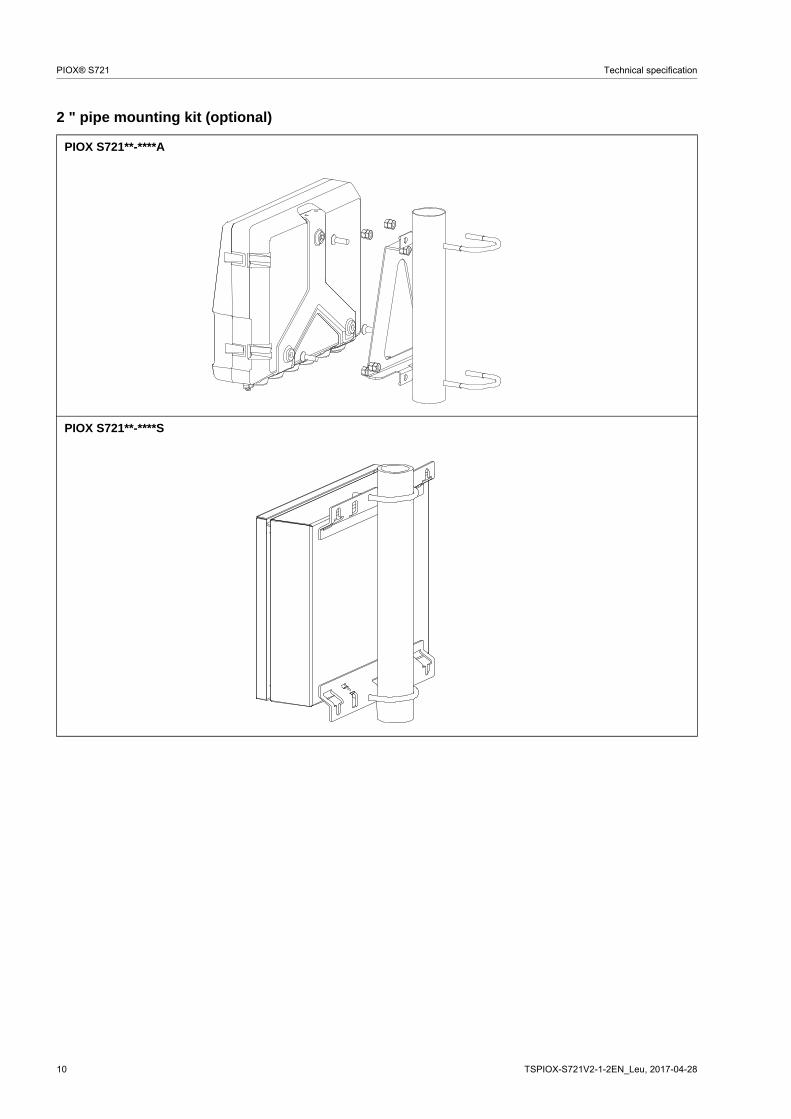
2 " pipe mounting kit (optional)
PIOX S721**-****A
PIOX S721**-****S
Technical specification PIOX® S721
TSPIOX-S721V2-1-2EN_Leu, 2017-04-28 11
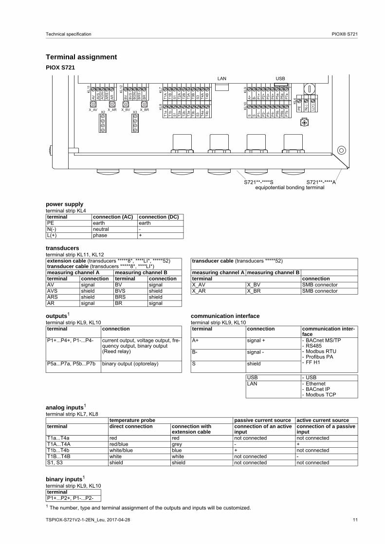
Terminal assignment
1 The number, type and terminal assignment of the outputs and inputs will be customized.
PIOX S721
power supplyterminal strip KL4terminal connection (AC) connection (DC)PE earth earthN(-) neutral -L(+) phase +
transducersterminal strip KL11, KL12extension cable (transducers *****8*, ****LI*, *****52)transducer cable (transducers *****8*, ****LI*)
transducer cable (transducers *****52)
measuring channel A measuring channel B measuring channel A measuring channel Bterminal connection terminal connection terminal connectionAV signal BV signal X_AV X_BV SMB connectorAVS shield BVS shield X_AR X_BR SMB connectorARS shield BRS shieldAR signal BR signal
outputs1 communication interfaceterminal strip KL9, KL10 terminal strip KL9, KL10terminal connection terminal connection communication inter-
faceP1+...P4+, P1-...P4- current output, voltage output, fre-
quency output, binary output (Reed relay)
A+ signal + - BACnet MS/TP- RS485- Modbus RTU- Profibus PA- FF H1
B- signal -
P5a...P7a, P5b...P7b binary output (optorelay) S shield
USB - USBLAN - Ethernet
- BACnet IP- Modbus TCP
analog inputs1
terminal strip KL7, KL8temperature probe passive current source active current source
terminal direct connection connection with extension cable
connection of an active input
connection of a passive input
T1a...T4a red red not connected not connectedT1A...T4A red/blue grey - +T1b...T4b white/blue blue + not connectedT1B...T4B white white not connected -S1, S3 shield shield not connected not connected
binary inputs1
terminal strip KL9, KL10terminalP1+...P2+, P1-...P2-
A+B-P1+P2+P3+P4+P5aP6aP7a
S S P1-P2-P3-P4-P5bP6bP7bX2 X3
X_AV
KL11
KL12
KL7
KL8
KL9
KL10 KL4
X_AR X_BV X_BR
T1A
T1B
S1T2A
T2B
T3A
T3B
S3
T4B
T4A
T1a
T1b
S1T2a
T2b
T3a
T3b
S3
T4b
T4a
N(-)
PE L(+)
AV AVS
AGN
ARS
AR
BVBVS
BGN
BRS
BR
S721**-****S S721**-****Aequipotential bonding terminal
LAN USB
12 TSPIOX-S721V2-1-2EN_Leu, 2017-04-28
PIOX® S721 Technical specification
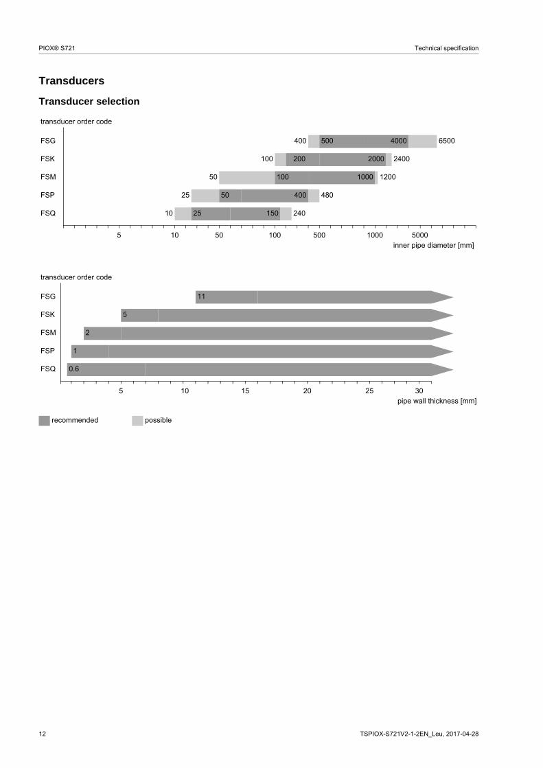
Transducers
Transducer selection
transducer order code
FSG 400 500 4000 6500
FSK 100 200 2000 2400
FSM 50 100 1000 1200
FSP 25 50 400 480
FSQ 10 25 150 240
5 10 50 100 500 1000 5000inner pipe diameter [mm]
transducer order code
FSG 11
FSK 5
FSM 2
FSP 1
FSQ 0.6
5 10 15 20 25 30pipe wall thickness [mm]
recommended possible

Technical specification PIOX® S721
TSPIOX-S721V2-1-2EN_Leu, 2017-04-28 13
Transducer order code
1, 2 3 4 5, 6 7, 8 9...11 12, 13 no. of character
tra
nsdu
cer
tra
nsdu
cer
fre
quen
cy
- ambi
ent
tem
pera
ture
expl
osio
n pr
ote
ctio
n
conn
ectio
n sy
stem
- exte
nsio
n ca
ble
/ optio
n
description
FS set of ultrasonic flow transducers for liquids measurement, shear wave
G 0.2 MHz
K 0.5 MHz
M 1 MHz
P 2 MHz
Q 4 MHz
N normal temperature range
E extended temperature range (FSM, FSP, FSQ)
A1 ATEX zone 1/IECEx zone 1
A2 ATEX zone 2/IECEx zone 2
F2 FM Class I Div. 2
NN not explosion proof
TS direct connection or connection via junction box
XXX cable length in m, for max. length of extension cable see page 26
connection system TS:
0 m: without junction box
> 0 m: with junction box
LC long transducer cable
IP68 degree of protection IP68
OS housing with stainless steel 316
example
FS M - N A1 TS - 030 shear wave transducer 1 MHz, normal temperature range, ATEX zone 1/IECEx zone 1, connection system TS with junction box JB01 and extension cable 30 m
- - /

14 TSPIOX-S721V2-1-2EN_Leu, 2017-04-28
PIOX® S721 Technical specification
Technical data
Shear wave transducers (zone 1)
technical type CDG1N81 CDK1N81order code FSG-NA1TS
FSG-NA1TS/OSFSK-NA1TSFSK-NA1TS/OS
transducer frequency MHz 0.2 0.5
inner pipe diameter dmin. extended mm 400 100min. recommended mm 500 200max. recommended mm 4000 2000max. extended mm 6500 2400pipe wall thicknessmin. mm 11 5materialhousing PEEK with stainless steel
cap 304 (1.4301), option OS: 316L (1.4404)
PEEK with stainless steel cap 304 (1.4301), option OS: 316L (1.4404)
contact surface PEEK PEEKdegree of protection according to IEC/EN 60529
IP65 IP66
transducer cabletype 1699 1699length m 5 5dimensionslength l mm 129.5 126.5width b mm 51 51height h mm 67 67.5dimensional drawing
ambient temperaturemin. °C -40 -40max. °C +130 +130temperature compen-sation
x x
explosion protection
ATEX/IECEx
categoryEPLzone
gas: 2G dust: 2DGb Db1 21
gas: 2G dust: 2DGb Db1 21
explosion protection temperature (pipe surface)min. °C -55 -55max. °C +180 +180marking
Ex q IIC T6...T3 GbEx tb IIIC TX Db
Ex q IIC T6...T3 GbEx tb IIIC TX Db
certification ATEX IBExU07ATEX1168 X IBExU07ATEX1168 Xcertification IECEx IECEx IBE 08.0007X IECEx IBE 08.0007Xtype of protection gas: increased safety,
powder fillingdust: protection by enclosure
gas: increased safety, powder fillingdust: protection by enclosure
transducer mounting fixture necessary
x x
l
hb
l
hb
II2GII2D
0637 II2GII2D
0637
Technical specification PIOX® S721
TSPIOX-S721V2-1-2EN_Leu, 2017-04-28 15
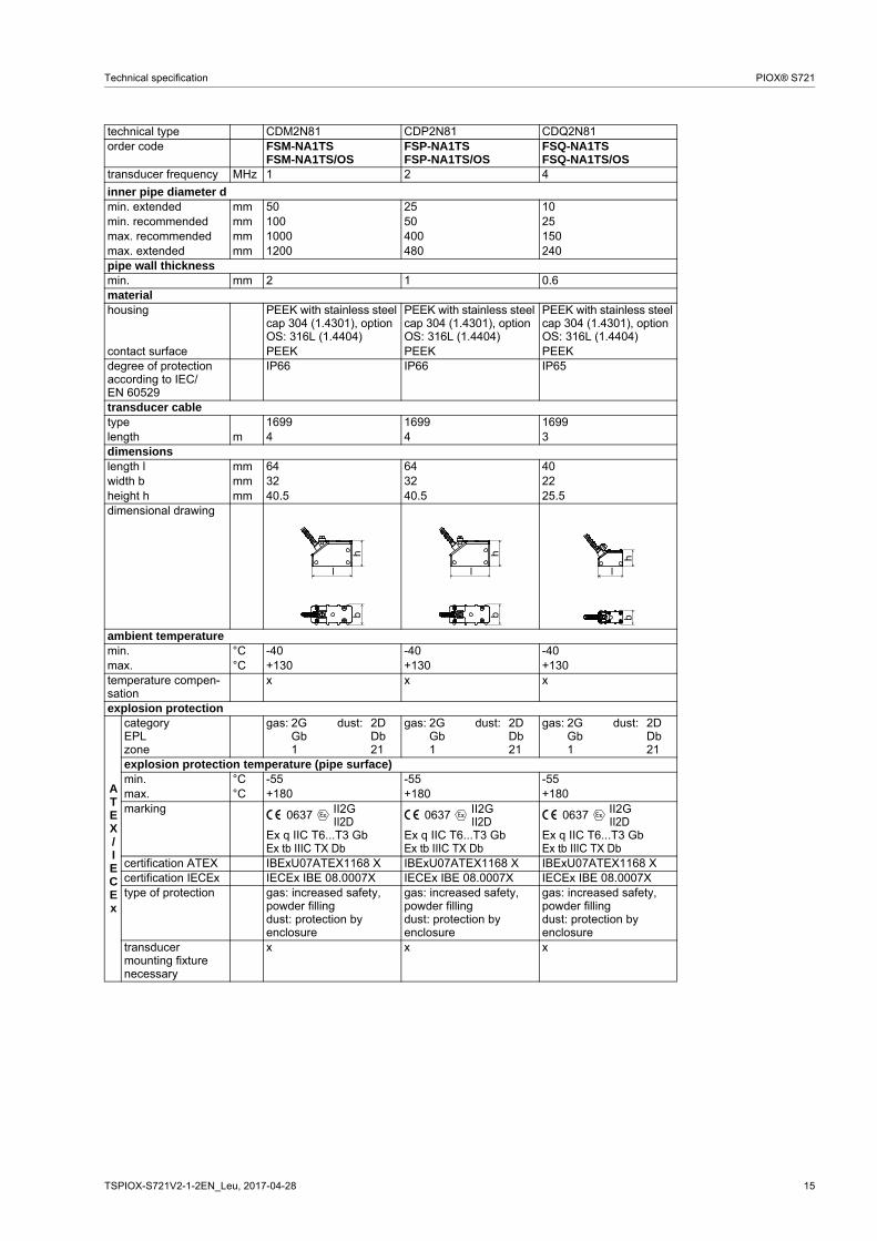
technical type CDM2N81 CDP2N81 CDQ2N81order code FSM-NA1TS
FSM-NA1TS/OSFSP-NA1TSFSP-NA1TS/OS
FSQ-NA1TSFSQ-NA1TS/OS
transducer frequency MHz 1 2 4
inner pipe diameter dmin. extended mm 50 25 10min. recommended mm 100 50 25max. recommended mm 1000 400 150max. extended mm 1200 480 240pipe wall thicknessmin. mm 2 1 0.6materialhousing PEEK with stainless steel
cap 304 (1.4301), option OS: 316L (1.4404)
PEEK with stainless steel cap 304 (1.4301), option OS: 316L (1.4404)
PEEK with stainless steel cap 304 (1.4301), option OS: 316L (1.4404)
contact surface PEEK PEEK PEEKdegree of protection according to IEC/EN 60529
IP66 IP66 IP65
transducer cabletype 1699 1699 1699length m 4 4 3dimensionslength l mm 64 64 40width b mm 32 32 22height h mm 40.5 40.5 25.5dimensional drawing
ambient temperaturemin. °C -40 -40 -40max. °C +130 +130 +130temperature compen-sation
x x x
explosion protection
ATEX/IECEx
categoryEPLzone
gas: 2G dust: 2DGb Db1 21
gas: 2G dust: 2DGb Db1 21
gas: 2G dust: 2DGb Db1 21
explosion protection temperature (pipe surface)min. °C -55 -55 -55max. °C +180 +180 +180marking
Ex q IIC T6...T3 GbEx tb IIIC TX Db
Ex q IIC T6...T3 GbEx tb IIIC TX Db
Ex q IIC T6...T3 GbEx tb IIIC TX Db
certification ATEX IBExU07ATEX1168 X IBExU07ATEX1168 X IBExU07ATEX1168 Xcertification IECEx IECEx IBE 08.0007X IECEx IBE 08.0007X IECEx IBE 08.0007Xtype of protection gas: increased safety,
powder fillingdust: protection by enclosure
gas: increased safety, powder fillingdust: protection by enclosure
gas: increased safety, powder fillingdust: protection by enclosure
transducer mounting fixture necessary
x x x
l
hb
l
hb
hb
l
II2GII2D
0637 II2GII2D
0637 II2GII2D
0637
16 TSPIOX-S721V2-1-2EN_Leu, 2017-04-28
PIOX® S721 Technical specification
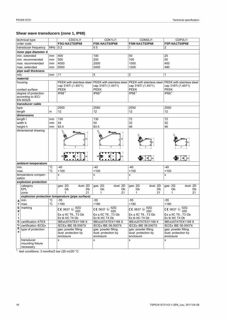
Shear wave transducers (zone 1, IP68)
technical type CDG1LI1 CDK1LI1 CDM2LI1 CDP2LI1order code FSG-NA1TS/IP68 FSK-NA1TS/IP68 FSM-NA1TS/IP68 FSP-NA1TS/IP68transducer frequency MHz 0.2 0.5 1 2
inner pipe diameter dmin. extended mm 400 100 50 25min. recommended mm 500 200 100 50max. recommended mm 4000 2000 1000 400max. extended mm 6500 2400 1200 480pipe wall thicknessmin. mm 11 5 2 1materialhousing PEEK with stainless steel
cap 316Ti (1.4571)PEEK with stainless steel cap 316Ti (1.4571)
PEEK with stainless steel cap 316Ti (1.4571)
PEEK with stainless steel cap 316Ti (1.4571)
contact surface PEEK PEEK PEEK PEEKdegree of protection according to IEC/EN 60529
IP68 IP68 IP68 IP68
transducer cabletype 2550 2550 2550 2550length m 12 12 12 12dimensionslength l mm 130 130 72 72width b mm 54 54 32 32height h mm 83.5 83.5 46 46dimensional drawing
ambient temperaturemin. °C -40 -40 -40 -40max. °C +100 +100 +100 +100temperature compen-sation
x x x x
explosion protection
ATEX/IECEx
categoryEPLzone
gas: 2G dust: 2DGb Db1 21
gas: 2G dust: 2DGb Db1 21
gas: 2G dust: 2DGb Db1 21
gas: 2G dust: 2DGb Db1 21
explosion protection temperature (pipe surface)min. °C -55 -55 -55 -55max. °C +180 +180 +180 +180marking
Ex q IIC T6...T3 GbEx tb IIIC TX Db
Ex q IIC T6...T3 GbEx tb IIIC TX Db
Ex q IIC T6...T3 GbEx tb IIIC TX Db
Ex q IIC T6...T3 GbEx tb IIIC TX Db
certification ATEX IBExU07ATEX1168 X IBExU07ATEX1168 X IBExU07ATEX1168 X IBExU07ATEX1168 Xcertification IECEx IECEx IBE 08.0007X IECEx IBE 08.0007X IECEx IBE 08.0007X IECEx IBE 08.0007Xtype of protection gas: powder filling
dust: protection by enclosure
gas: powder fillingdust: protection by enclosure
gas: powder fillingdust: protection by enclosure
gas: powder fillingdust: protection by enclosure
transducer mounting fixture necessary
x x x x
1 test conditions: 3 months/2 bar (20 m)/20 °C
1 1 1 1
l
hb
l
hb
l
hb
l
hb
II2GII2D
0637 II2GII2D
0637 II2GII2D
0637 II2GII2D
0637

Technical specification PIOX® S721
TSPIOX-S721V2-1-2EN_Leu, 2017-04-28 17
Shear wave transducers (zone 1, extended temperature range)
technical type CDM2E85 CDP2E85 CDQ2E85order code FSM-EA1TS
FSM-EA1TS/OSFSP-EA1TSFSP-EA1TS/OS
FSQ-EA1TSFSQ-EA1TS/OS
transducer frequency MHz 1 2 4
inner pipe diameter dmin. extended mm 50 25 10min. recommended mm 100 50 25max. recommended mm 1000 400 150max. extended mm 1200 480 240pipe wall thicknessmin. mm 2 1 0.6materialhousing PI with stainless steel
cap 304 (1.4301), option OS: 316L (1.4404)
PI with stainless steel cap 304 (1.4301), option OS: 316L (1.4404)
PI with stainless steel cap 304 (1.4301), option OS: 316L (1.4404)
contact surface PI PI PIdegree of protection according to IEC/EN 60529
IP66 IP66 IP56
transducer cabletype 6111 6111 6111length m 4 4 3dimensionslength l mm 64 64 40width b mm 32 32 22height h mm 40.5 40.5 25.5dimensional drawing
ambient temperaturemin. °C -30 -30 -30max. °C +200 +200 +200temperature compen-sation
x x x
explosion protection
ATEX/IECEx
categoryEPLzone
gas: 2G dust: 2DGb Db1 21
gas: 2G dust: 2DGb Db1 21
gas: 2G dust: 2DGb Db1 21
explosion protection temperature (pipe surface)min. °C -45 -45 -45max. °C +225 +225 +225marking
Ex q IIC T6...T2 GbEx tb IIIA TX Db
Ex q IIC T6...T2 GbEx tb IIIA TX Db
Ex q IIC T6...T2 GbEx tb IIIA TX Db
certification ATEX IBExU07ATEX1168 X IBExU07ATEX1168 X IBExU07ATEX1168 Xcertification IECEx IECEx IBE 08.0007X IECEx IBE 08.0007X IECEx IBE 08.0007Xtype of protection gas: increased safety,
powder fillingdust: protection by enclosure
gas: increased safety, powder fillingdust: protection by enclosure
gas: increased safety, powder fillingdust: protection by enclosure
transducer mounting fixture necessary
x x x
l
hb
l
hb
hb
l
II2GII2D
0637 II2GII2D
0637 II2GII2D
0637

18 TSPIOX-S721V2-1-2EN_Leu, 2017-04-28
PIOX® S721 Technical specification
Shear wave transducers (zone 2, FM Div. 2 or not explosion proof)
technical type CDG1N52 CLG1N52 CDK1N52 CLK1N52order code FSG-NA2TS
FSG-NA2TS/OSFSG-NF2TSFSG-NF2TS/OSFSG-NNNTSFSG-NNNTS/OS
FSG-NA2TS/LCFSG-NA2TS/LC/OSFSG-NF2TS/LCFSG-NF2TS/LC/OSFSG-NNNTS/LCFSG-NNNTS/LC/OS
FSK-NA2TSFSK-NA2TS/OSFSK-NF2TSFSK-NF2TS/OSFSK-NNNTSFSK-NNNTS/OS
FSK-NA2TS/LCFSK-NA2TS/LC/OSFSK-NF2TS/LCFSK-NF2TS/LC/OSFSK-NNNTS/LCFSK-NNNTS/LC/OS
transducer frequency MHz 0.2 0.2 0.5 0.5inner pipe diameter dmin. extended mm 400 400 100 100min. recommended mm 500 500 200 200max. recommended mm 4000 4000 2000 2000max. extended mm 6500 6500 2400 2400pipe wall thicknessmin. mm 11 11 5 5materialhousing PEEK with stainless steel
cap 304 (1.4301), option OS: 316L (1.4404)
PEEK with stainless steel cap 304 (1.4301), option OS: 316L (1.4404)
PEEK with stainless steel cap 304 (1.4301), option OS: 316L (1.4404)
PEEK with stainless steel cap 304 (1.4301), option OS: 316L (1.4404)
contact surface PEEK PEEK PEEK PEEKdegree of protection according to IEC/EN 60529
IP67 IP67 IP67 IP67
transducer cabletype 1699 1699 1699 1699length m 5 9 5 9dimensionslength l mm 129.5 129.5 126.5 126.5width b mm 51 51 51 51height h mm 67 67 67.5 67.5dimensional drawing
ambient temperaturemin. °C -40 -40 -40 -40max. °C +130 +130 +130 +130temperature compen-sation
x x x x
continued on next page
l
hb
l
hb
l
hb
l
hb

Technical specification PIOX® S721
TSPIOX-S721V2-1-2EN_Leu, 2017-04-28 19
explosion protection
ATEX/IECEx
order code FSG-NA2TSFSG-NA2TS/OS
FSG-NA2TS/LCFSG-NA2TS/LC/OS
FSK-NA2TSFSK-NA2TS/OS
FSK-NA2TS/LCFSK-NA2TS/LC/OS
categoryEPLzone
gas: 3G dust: 2DGc Db2 21
gas: 3G dust: 2DGc Db2 21
gas: 3G dust: 2DGc Db2 21
gas: 3G dust: 2DGc Db2 21
explosion protection temperature (pipe surface)min. °C -55 -55 -55 -55max. °C gas: +190, dust: +180 gas: +190, dust: +180 gas: +190, dust: +180 gas: +190, dust: +180marking
Ex nA IIC T6...T2 GcEx tb IIIC TX Db
Ex nA IIC T6...T2 GcEx tb IIIC TX Db
Ex nA IIC T6...T2 GcEx tb IIIC TX Db
Ex nA IIC T6...T2 GcEx tb IIIC TX Db
certification ATEX IBExU10ATEX1163 X IBExU10ATEX1163 X IBExU10ATEX1163 X IBExU10ATEX1163 Xcertification IECEx IECEx IBE 12.0005X IECEx IBE 12.0005X IECEx IBE 12.0005X IECEx IBE 12.0005Xtype of protection gas: non sparking
dust: protection by enclosure
gas: non sparkingdust: protection by enclosure
gas: non sparkingdust: protection by enclosure
gas: non sparkingdust: protection by enclosure
transducer mounting fixture necessary
x x x x
FM
order code FSG-NF2TSFSG-NF2TS/OS
FSG-NF2TS/LCFSG-NF2TS/LC/OS
FSK-NF2TSFSK-NF2TS/OS
FSK-NF2TS/LCFSK-NF2TS/LC/OS
explosion protection temperaturemin. °C -40 -40 -40 -40max. °C +125 +125 +125 +125marking NI/Cl. I,II,III/Div. 2 /
GP A,B,C,D,E,F,G/Temp. Codes dwg 3860
NI/Cl. I,II,III/Div. 2 /GP A,B,C,D,E,F,G/
Temp. Codes dwg 3860
NI/Cl. I,II,III/Div. 2 /GP A,B,C,D,E,F,G/
Temp. Codes dwg 3860
NI/Cl. I,II,III/Div. 2 /GP A,B,C,D,E,F,G/
Temp. Codes dwg 3860type of protection non incendive non incendive non incendive non incendive
technical type CDG1N52 CLG1N52 CDK1N52 CLK1N52
II3GII2D
0637 II3GII2D
0637 II3GII2D
0637 II3GII2D
0637
20 TSPIOX-S721V2-1-2EN_Leu, 2017-04-28
PIOX® S721 Technical specification
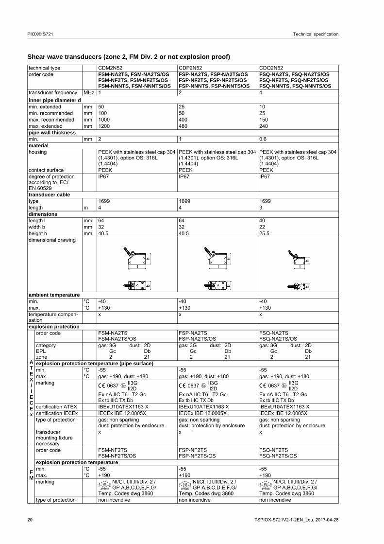
Shear wave transducers (zone 2, FM Div. 2 or not explosion proof)
technical type CDM2N52 CDP2N52 CDQ2N52order code FSM-NA2TS, FSM-NA2TS/OS
FSM-NF2TS, FSM-NF2TS/OSFSM-NNNTS, FSM-NNNTS/OS
FSP-NA2TS, FSP-NA2TS/OSFSP-NF2TS, FSP-NF2TS/OSFSP-NNNTS, FSP-NNNTS/OS
FSQ-NA2TS, FSQ-NA2TS/OSFSQ-NF2TS, FSQ-NF2TS/OSFSQ-NNNTS, FSQ-NNNTS/OS
transducer frequency MHz 1 2 4
inner pipe diameter dmin. extended mm 50 25 10min. recommended mm 100 50 25max. recommended mm 1000 400 150max. extended mm 1200 480 240pipe wall thicknessmin. mm 2 1 0.6materialhousing PEEK with stainless steel cap 304
(1.4301), option OS: 316L (1.4404)
PEEK with stainless steel cap 304 (1.4301), option OS: 316L (1.4404)
PEEK with stainless steel cap 304 (1.4301), option OS: 316L (1.4404)
contact surface PEEK PEEK PEEKdegree of protection according to IEC/EN 60529
IP67 IP67 IP67
transducer cabletype 1699 1699 1699length m 4 4 3dimensionslength l mm 64 64 40width b mm 32 32 22height h mm 40.5 40.5 25.5dimensional drawing
ambient temperaturemin. °C -40 -40 -40max. °C +130 +130 +130temperature compen-sation
x x x
explosion protection
ATEX/IECEx
order code FSM-NA2TSFSM-NA2TS/OS
FSP-NA2TSFSP-NA2TS/OS
FSQ-NA2TSFSQ-NA2TS/OS
categoryEPLzone
gas: 3G dust: 2DGc Db2 21
gas: 3G dust: 2DGc Db2 21
gas: 3G dust: 2DGc Db2 21
explosion protection temperature (pipe surface)min. °C -55 -55 -55max. °C gas: +190, dust: +180 gas: +190, dust: +180 gas: +190, dust: +180marking
Ex nA IIC T6...T2 GcEx tb IIIC TX Db
Ex nA IIC T6...T2 GcEx tb IIIC TX Db
Ex nA IIC T6...T2 GcEx tb IIIC TX Db
certification ATEX IBExU10ATEX1163 X IBExU10ATEX1163 X IBExU10ATEX1163 Xcertification IECEx IECEx IBE 12.0005X IECEx IBE 12.0005X IECEx IBE 12.0005Xtype of protection gas: non sparking
dust: protection by enclosuregas: non sparkingdust: protection by enclosure
gas: non sparkingdust: protection by enclosure
transducer mounting fixture necessary
x x x
FM
order code FSM-NF2TSFSM-NF2TS/OS
FSP-NF2TSFSP-NF2TS/OS
FSQ-NF2TSFSQ-NF2TS/OS
explosion protection temperaturemin. °C -55 -55 -55max. °C +190 +190 +190marking NI/Cl. I,II,III/Div. 2 /
GP A,B,C,D,E,F,G/Temp. Codes dwg 3860
NI/Cl. I,II,III/Div. 2 /GP A,B,C,D,E,F,G/
Temp. Codes dwg 3860
NI/Cl. I,II,III/Div. 2 /GP A,B,C,D,E,F,G/
Temp. Codes dwg 3860type of protection non incendive non incendive non incendive
l
hb
l
hb
hb
l
II3GII2D
0637 II3GII2D
0637 II3GII2D
0637

Technical specification PIOX® S721
TSPIOX-S721V2-1-2EN_Leu, 2017-04-28 21
Shear wave transducers (zone 2 or not explosion proof, IP68)
technical type CDG1LI8 CDK1LI8 CDM2LI8 CDP2LI8order code FSG-NA2TS/IP68
FSG-NNNTS/IP68FSK-NA2TS/IP68FSK-NNNTS/IP68
FSM-NA2TS/IP68FSM-NNNTS/IP68
FSP-NA2TS/IP68FSP-NNNTS/IP68
transducer frequency MHz 0.2 0.5 1 2
inner pipe diameter dmin. extended mm 400 100 50 25min. recommended mm 500 200 100 50max. recommended mm 4000 2000 1000 400max. extended mm 6500 2400 1200 480pipe wall thicknessmin. mm 11 5 2 1materialhousing PEEK with stainless steel
cap 316Ti (1.4571)PEEK with stainless steel cap 316Ti (1.4571)
PEEK with stainless steel cap 316Ti (1.4571)
PEEK with stainless steel cap 316Ti (1.4571)
contact surface PEEK PEEK PEEK PEEKdegree of protection according to IEC/EN 60529
IP68 IP68 IP68 IP68
transducer cabletype 2550 2550 2550 2550length m 12 12 12 12dimensionslength l mm 130 130 72 72width b mm 54 54 32 32height h mm 83.5 83.5 46 46dimensional drawing
ambient temperaturemin. °C -40 -40 -40 -40max. °C +100 +100 +100 +100temperature compen-sation
x x x x
explosion protection
ATEX/IECEx
order code FSG-NA2TS/IP68 FSK-NA2TS/IP68 FSM-NA2TS/IP68 FSP-NA2TS/IP68categoryEPLzone
gas: 3G dust: 2DGc Db2 21
gas: 3G dust: 2DGc Db2 21
gas: 3G dust: 2DGc Db2 21
gas: 3G dust: 2DGc Db2 21
explosion protection temperature (pipe surface)min. °C -40 -40 -40 -40max. °C +90 +90 +90 +90marking
Ex nA IIC T6...T2 GcEx tb IIIC TX Db
Ex nA IIC T6...T2 GcEx tb IIIC TX Db
Ex nA IIC T6...T2 GcEx tb IIIC TX Db
Ex nA IIC T6...T2 GcEx tb IIIC TX Db
certification ATEX IBExU10ATEX1163 X IBExU10ATEX1163 X IBExU10ATEX1163 X IBExU10ATEX1163 Xcertification IECEx IECEx IBE 12.0005X IECEx IBE 12.0005X IECEx IBE 12.0005X IECEx IBE 12.0005Xtype of protection gas: non sparking
dust: protection by enclosure
gas: non sparkingdust: protection by enclosure
gas: non sparkingdust: protection by enclosure
gas: non sparkingdust: protection by enclosure
transducer mounting fixture necessary
x x x x
1 test conditions: 3 months/2 bar (20 m)/20 °C
1 1 1 1
l
hb
l
hb
l
hb
l
hb
II3GII2D
0637 II3GII2D
0637 II3GII2D
0637 II3GII2D
0637
22 TSPIOX-S721V2-1-2EN_Leu, 2017-04-28
PIOX® S721 Technical specification
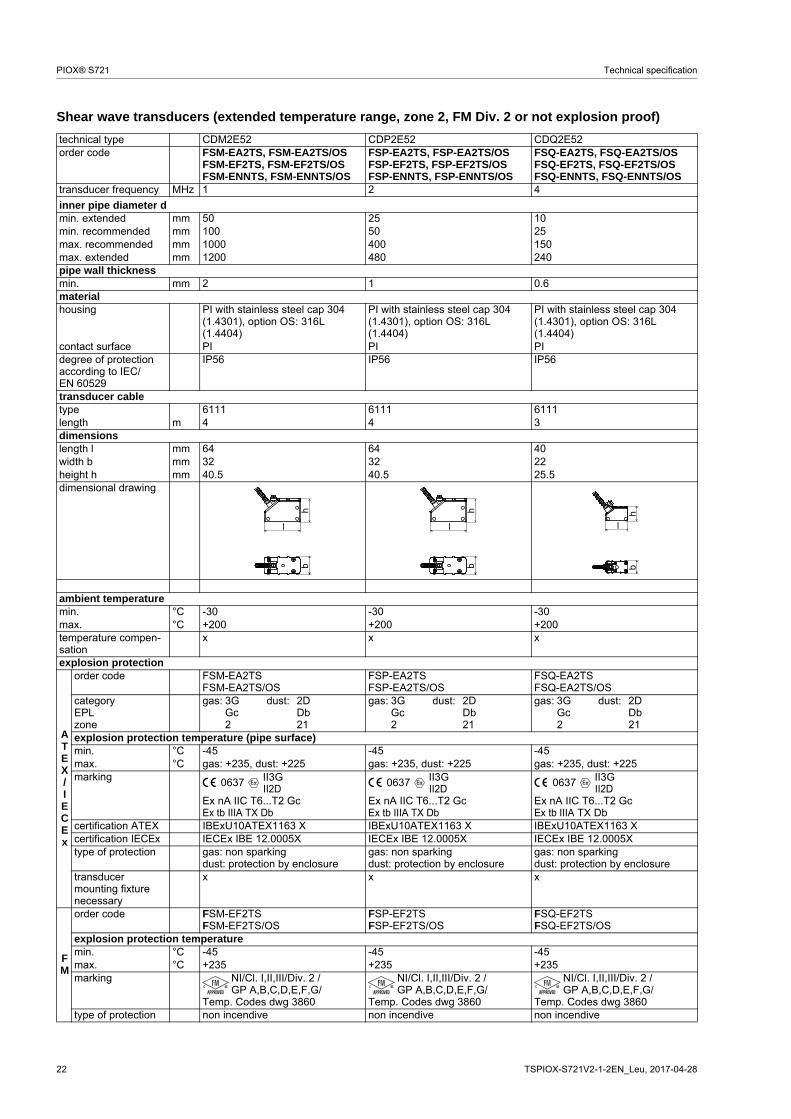
Shear wave transducers (extended temperature range, zone 2, FM Div. 2 or not explosion proof)
technical type CDM2E52 CDP2E52 CDQ2E52order code FSM-EA2TS, FSM-EA2TS/OS
FSM-EF2TS, FSM-EF2TS/OSFSM-ENNTS, FSM-ENNTS/OS
FSP-EA2TS, FSP-EA2TS/OSFSP-EF2TS, FSP-EF2TS/OSFSP-ENNTS, FSP-ENNTS/OS
FSQ-EA2TS, FSQ-EA2TS/OSFSQ-EF2TS, FSQ-EF2TS/OSFSQ-ENNTS, FSQ-ENNTS/OS
transducer frequency MHz 1 2 4
inner pipe diameter dmin. extended mm 50 25 10min. recommended mm 100 50 25max. recommended mm 1000 400 150max. extended mm 1200 480 240pipe wall thicknessmin. mm 2 1 0.6materialhousing PI with stainless steel cap 304
(1.4301), option OS: 316L (1.4404)
PI with stainless steel cap 304 (1.4301), option OS: 316L (1.4404)
PI with stainless steel cap 304 (1.4301), option OS: 316L (1.4404)
contact surface PI PI PIdegree of protection according to IEC/EN 60529
IP56 IP56 IP56
transducer cabletype 6111 6111 6111length m 4 4 3dimensionslength l mm 64 64 40width b mm 32 32 22height h mm 40.5 40.5 25.5dimensional drawing
ambient temperaturemin. °C -30 -30 -30max. °C +200 +200 +200temperature compen-sation
x x x
explosion protection
ATEX/IECEx
order code FSM-EA2TSFSM-EA2TS/OS
FSP-EA2TSFSP-EA2TS/OS
FSQ-EA2TSFSQ-EA2TS/OS
categoryEPLzone
gas: 3G dust: 2DGc Db2 21
gas: 3G dust: 2DGc Db2 21
gas: 3G dust: 2DGc Db2 21
explosion protection temperature (pipe surface)min. °C -45 -45 -45max. °C gas: +235, dust: +225 gas: +235, dust: +225 gas: +235, dust: +225marking
Ex nA IIC T6...T2 GcEx tb IIIA TX Db
Ex nA IIC T6...T2 GcEx tb IIIA TX Db
Ex nA IIC T6...T2 GcEx tb IIIA TX Db
certification ATEX IBExU10ATEX1163 X IBExU10ATEX1163 X IBExU10ATEX1163 Xcertification IECEx IECEx IBE 12.0005X IECEx IBE 12.0005X IECEx IBE 12.0005Xtype of protection gas: non sparking
dust: protection by enclosuregas: non sparkingdust: protection by enclosure
gas: non sparkingdust: protection by enclosure
transducer mounting fixture necessary
x x x
FM
order code FSM-EF2TSFSM-EF2TS/OS
FSP-EF2TSFSP-EF2TS/OS
FSQ-EF2TSFSQ-EF2TS/OS
explosion protection temperaturemin. °C -45 -45 -45max. °C +235 +235 +235marking NI/Cl. I,II,III/Div. 2 /
GP A,B,C,D,E,F,G/Temp. Codes dwg 3860
NI/Cl. I,II,III/Div. 2 /GP A,B,C,D,E,F,G/
Temp. Codes dwg 3860
NI/Cl. I,II,III/Div. 2 /GP A,B,C,D,E,F,G/
Temp. Codes dwg 3860type of protection non incendive non incendive non incendive
l
hb
l
hb
hb
l
II3GII2D
0637 II3GII2D
0637 II3GII2D
0637

Technical specification PIOX® S721
TSPIOX-S721V2-1-2EN_Leu, 2017-04-28 23
Transducer mounting fixture
Order code
1, 2 3 4 5 6 7...9 10, 11 no. of character
tran
sduc
er
mou
ntin
g fix
ture
tran
sduc
er
- mea
sure
men
t ar
rang
emen
t
size
- fixat
ion
oute
r pi
pe d
iam
e-te
r
/ optio
n
description
VL Variofix L
VС Variofix C
K transducers with transducer frequency G, K
M transducers with transducer frequency M, P
Q transducers with transducer frequency Q
D reflection arrangement or diagonal arrangement
R reflection arrangement
S small
M medium
L large
S tension straps
W welding
N without fixation
002 10...20 mm
004 20...40 mm
T36 40...360 mm
013 10...130 mm
036 130...360 mm
092 360...920 mm
200 920...2000 mm
450 2000...4500 mm
940 4500...9400 mm
NDR any
IP68 degree of protection IP68
OS housing with stainless steel 316
Z special design
example
VL M - D S - S 200 Variofix L and tension straps for transducers with transducer fre-quency M, P
- - /
24 TSPIOX-S721V2-1-2EN_Leu, 2017-04-28
PIOX® S721 Technical specification
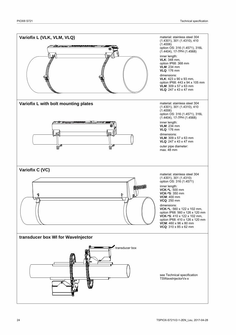
Variofix L (VLK, VLM, VLQ) material: stainless steel 304 (1.4301), 301 (1.4310), 410 (1.4006)option OS: 316 (1.4571), 316L (1.4404), 17-7PH (1.4568)
inner length:VLK: 348 mm,option IP68: 368 mmVLM: 234 mmVLQ: 176 mm
dimensions:VLK: 423 x 90 x 93 mm,option IP68: 443 x 94 x 105 mmVLM: 309 x 57 x 63 mmVLQ: 247 x 43 x 47 mm
Variofix L with bolt mounting plates material: stainless steel 304 (1.4301), 301 (1.4310), 410 (1.4006)option OS: 316 (1.4571), 316L (1.4404), 17-7PH (1.4568)
inner length:VLM: 234 mmVLQ: 176 mm
dimensions:VLM: 309 x 57 x 63 mmVLQ: 247 x 43 x 47 mm
outer pipe diameter:max. 48 mm
Variofix C (VC) material: stainless steel 304 (1.4301), 301 (1.4310)option OS: 316 (1.4571)
inner length:VCK-*L: 500 mmVCK-*S: 350 mmVCM: 400 mmVCQ: 250 mm
dimensions:VCK-*L: 560 x 122 x 102 mm,option IP68: 560 x 126 x 120 mmVCK-*S: 410 x 122 x 102 mm,option IP68: 410 x 126 x 120 mmVCM: 460 x 96 x 80 mmVCQ: 310 x 85 x 62 mm
transducer box WI for WaveInjector
see Technical specificationTSWaveInjectorVx-x
transducer box
Technical specification PIOX® S721
TSPIOX-S721V2-1-2EN_Leu, 2017-04-28 25
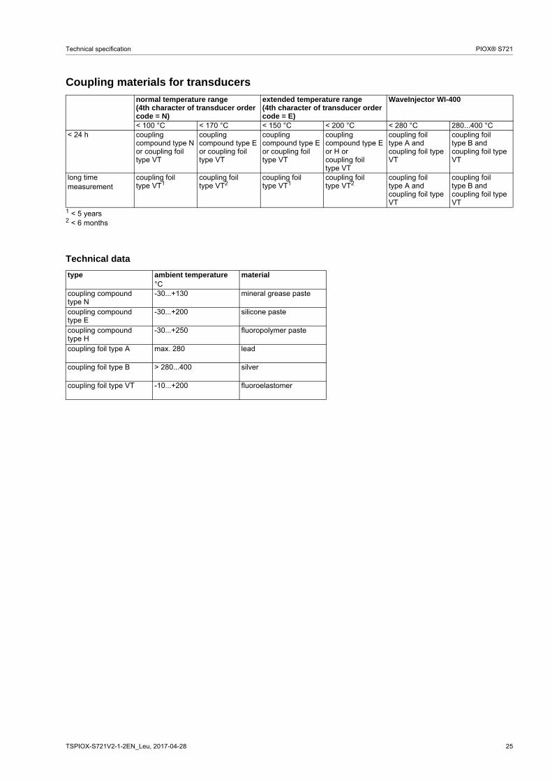
Coupling materials for transducers
Technical data
normal temperature range(4th character of transducer order code = N)
extended temperature range(4th character of transducer order code = E)
WaveInjector WI-400
< 100 °C < 170 °C < 150 °C < 200 °C < 280 °C 280...400 °C< 24 h coupling
compound type N or coupling foil type VT
coupling compound type E or coupling foil type VT
coupling compound type E or coupling foil type VT
coupling compound type E or H orcoupling foil type VT
coupling foil type A and coupling foil type VT
coupling foil type B and coupling foil type VT
long time measurement
coupling foil type VT1
coupling foil type VT2
coupling foil type VT1
coupling foil type VT2
coupling foil type A and coupling foil type VT
coupling foil type B and coupling foil type VT
1 < 5 years2 < 6 months
type ambient temperature material°C
coupling compound type N
-30...+130 mineral grease paste
coupling compound type E
-30...+200 silicone paste
coupling compound type H
-30...+250 fluoropolymer paste
coupling foil type A max. 280 lead
coupling foil type B > 280...400 silver
coupling foil type VT -10...+200 fluoroelastomer

26 TSPIOX-S721V2-1-2EN_Leu, 2017-04-28
PIOX® S721 Technical specification
Connection systemsconnection system TSconnection with extension cable direct connection transducers
technical type*****8*
****LI*
*****52
transducer frequency(3d character of transducer
order code)
F, G, H, K M, P Q S
TS
x l x l x l x lcable length m 5 ≤ 300 4 ≤ 300 3 ≤ 90 2 ≤ 40
cable length (option LC) m 9 ≤ 300 - - - - - -cable length (option IP68) m 12 ≤ 300 12 ≤ 300 - - - -
x, y - transducer cable lengthl - max. length of extension cable
tran
smitt
er
x
l
JB01
tran
smitt
er
x
tran
smitt
er
x
l
JB01, JBP2, JBP3
tran
smitt
er
x
tran
smitt
er
x
l
JB02, JB03
tran
smitt
er
x

Technical specification PIOX® S721
TSPIOX-S721V2-1-2EN_Leu, 2017-04-28 27
Transducer cable
Technical data
transducer cable extension cabletype 1699 2550 (option IP68) 6111 2615 5245standard length m see table above -max. length m - see table aboveambient temperature °C -55...+200 -40...+100 -100...+225 -30...+70 -30...+70properties longitudinal water
tighthalogen free
fire propagation test according to IEC 60332-1
combustion test according to IEC 60754-2
halogen free
fire propagation test according to IEC 60332-1
combustion test according to IEC 60754-2
cable jacketmaterial PTFE PUR PFA PUR PURouter diameter mm 2.9 5.2 ±0.2 2.7 12 12thickness mm 0.3 0.9 0.5 2 2colour brown grey white black blackshield x x x x xsheathmaterial stainless steel 304
(1.4301)- stainless steel 304
(1.4301)- steel wire braid with
copolymer sheathoption OS: 316Ti (1.4571)
option OS: 316Ti (1.4571)
outer diameter mm 8 - 8 - 15.6
28 TSPIOX-S721V2-1-2EN_Leu, 2017-04-28
PIOX® S721 Technical specification
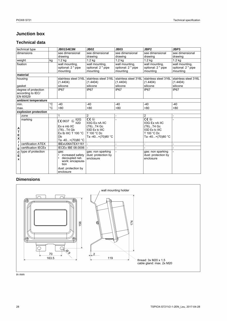
Junction box
Technical data
Dimensions
technical type JB01S4E3M JB02 JB03 JBP2 JBP3dimensions see dimensional
drawingsee dimensional drawing
see dimensional drawing
see dimensional drawing
see dimensional drawing
weight kg 1.2 kg 1.2 kg 1.2 kg 1.2 kg 1.2 kgfixation wall mounting,
optional: 2 " pipe mounting
wall mounting, optional: 2 " pipe mounting
wall mounting, optional: 2 " pipe mounting
wall mounting, optional: 2 " pipe mounting
wall mounting, optional: 2 " pipe mounting
materialhousing stainless steel 316L
(1.4404)stainless steel 316L (1.4404)
stainless steel 316L (1.4404)
stainless steel 316L (1.4404)
stainless steel 316L (1.4404)
gasket silicone silicone silicone silicone siliconedegree of protection according to IEC/EN 60529
IP67 IP67 IP67 IP67 IP67
ambient temperaturemin. °C -40 -40 -40 -40 -40max. °C +80 +80 +80 +80 +80explosion protection
ATEX/IECEx
zone 1 2 - 2 -marking
Ex e mb IIC (T6)...T4 GbEx tb IIIC T 100 °C DbTa -40...+(70)80 °C
II3G Ex nA IIC (T6)...T4 GcII3D Ex tc IIIC T 100 °C DcTa -40...+(70)80 °C
- II3G Ex nA IIC (T6)...T4 GcII3D Ex tc IIIC T 100 °C DcTa -40...+(70)80 °C
-
certification ATEX IBExU06ATEX1161 - - - -certification IECEx IECEx IBE 08.0006 - - - -type of protection gas:
• increased safety• decoupled net-
work: encapsula-tion
dust: protection by enclosure
gas: non sparkingdust: protection by enclosure
- gas: non sparkingdust: protection by enclosure
-
in mm
II2GII2D
0637
174
1192
wall mounting holder
70163.5
156
Ø 9
thread: 3x M20 x 1.5cable gland: max. 2x M20

Technical specification PIOX® S721
TSPIOX-S721V2-1-2EN_Leu, 2017-04-28 29
2 " pipe mounting kit (optional)
Terminal assignment
JB01
JB02, JB03
transducers
terminal strip KL1terminal connectionV transducer , signalVS transducer , internal shieldRS transducer , internal shieldR transducer , signalcable gland external shield
extension cable
terminal strip KL2terminal connectionTV signalTVS internal shieldTRS internal shieldTR signalshield terminal external shield
shield terminal
equipotential bonding terminal(at wall mounting holder)
transducers
terminal connectionXV transducer , SMB connectorXR transducer , SMB connectorcable gland external shield
extension cable
terminal strip KL2terminal connectionTV signalTVS internal shieldTRS internal shieldTR signalshield terminal external shield
shield terminal
equipotential bonding terminal(at wall mounting holder)
30 TSPIOX-S721V2-1-2EN_Leu, 2017-04-28
PIOX® S721 Technical specification
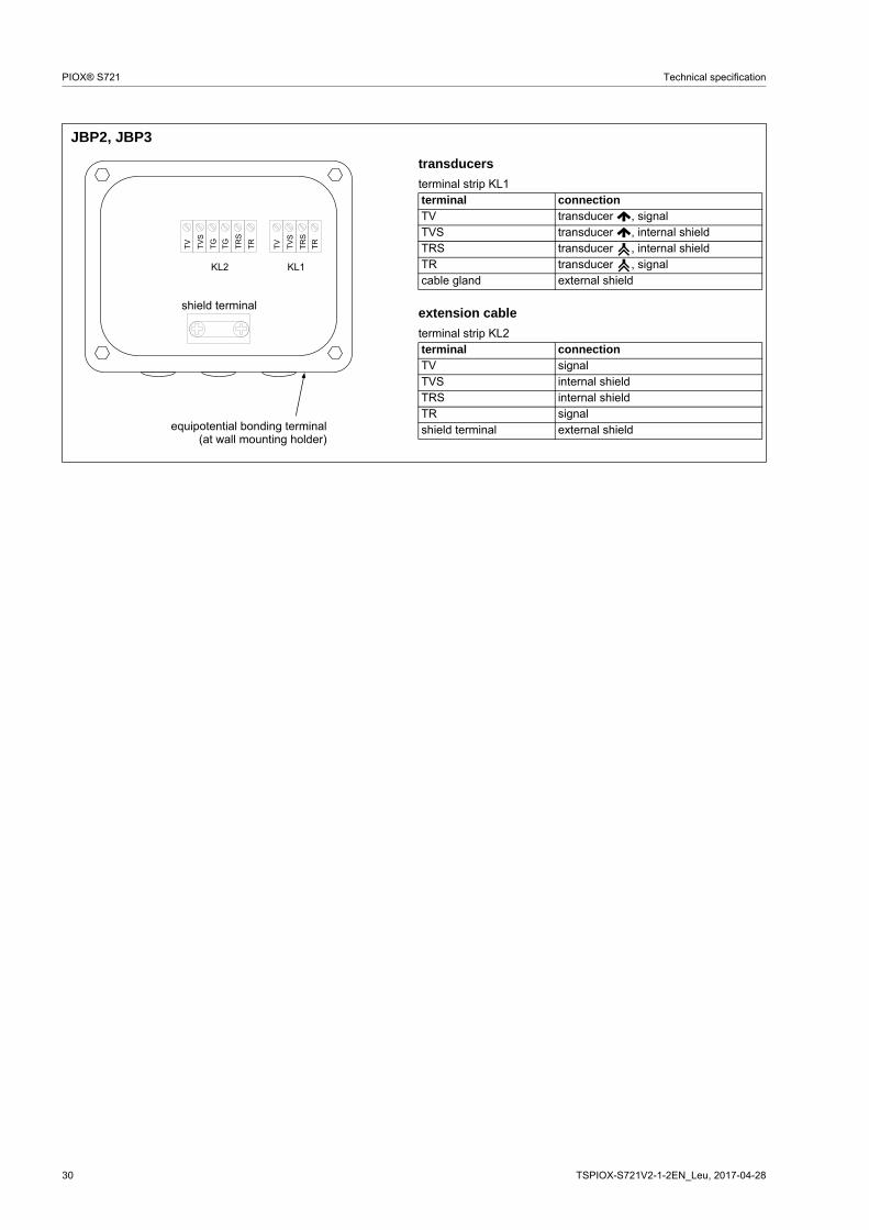
JBP2, JBP3
transducers
terminal strip KL1terminal connectionTV transducer , signalTVS transducer , internal shieldTRS transducer , internal shieldTR transducer , signalcable gland external shield
extension cable
terminal strip KL2terminal connectionTV signalTVS internal shieldTRS internal shieldTR signalshield terminal external shield
shield terminal
equipotential bonding terminal(at wall mounting holder)
Technical specification PIOX® S721
TSPIOX-S721V2-1-2EN_Leu, 2017-04-28 31
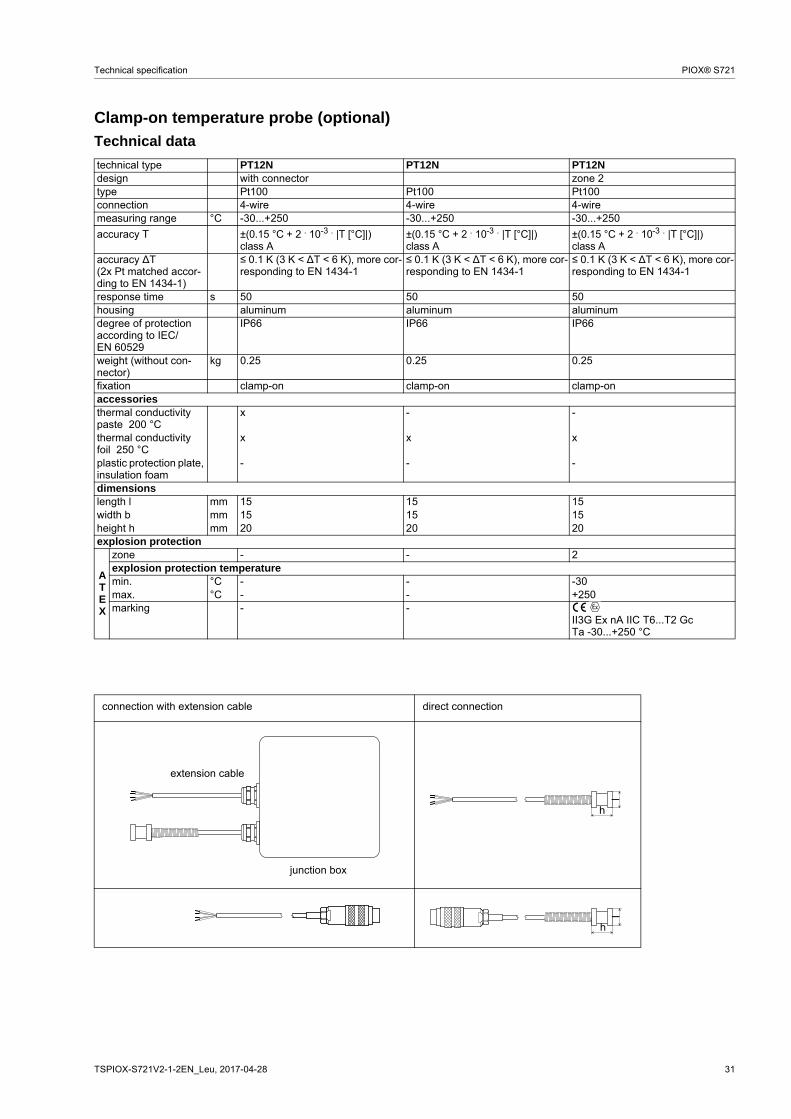
Clamp-on temperature probe (optional)
Technical data
technical type PT12N PT12N PT12Ndesign with connector zone 2type Pt100 Pt100 Pt100connection 4-wire 4-wire 4-wiremeasuring range °C -30...+250 -30...+250 -30...+250
accuracy T ±(0.15 °C + 2 . 10-3 . |T [°C]|)class A
±(0.15 °C + 2 . 10-3 . |T [°C]|)class A
±(0.15 °C + 2 . 10-3 . |T [°C]|)class A
accuracy ∆T(2x Pt matched accor-ding to EN 1434-1)
≤ 0.1 K (3 K < ∆T < 6 K), more cor-responding to EN 1434-1
≤ 0.1 K (3 K < ∆T < 6 K), more cor-responding to EN 1434-1
≤ 0.1 K (3 K < ∆T < 6 K), more cor-responding to EN 1434-1
response time s 50 50 50housing aluminum aluminum aluminumdegree of protection according to IEC/EN 60529
IP66 IP66 IP66
weight (without con-nector)
kg 0.25 0.25 0.25
fixation clamp-on clamp-on clamp-onaccessoriesthermal conductivity paste 200 °C
x - -
thermal conductivity foil 250 °C
x x x
plastic protection plate, insulation foam
- - -
dimensionslength l mm 15 15 15width b mm 15 15 15height h mm 20 20 20explosion protection
ATEX
zone - - 2explosion protection temperaturemin. °C - - -30max. °C - - +250marking - -
II3G Ex nA IIC T6...T2 GcTa -30...+250 °C
connection with extension cable direct connection
extension cable
junction box
l
h
h
l

32 TSPIOX-S721V2-1-2EN_Leu, 2017-04-28
PIOX® S721 Technical specification
Connection
Temperature probe
Connector
Cable
pin cable of temperature probe extension cable1 white/blue blue2 red/blue grey3, 4, 5 not connected6 red red7 white white8 not connected
cable of temperature probe
extension cable
type 4 x 0.25 mm² black LIYCY 8 x 0.14 mm² greystandard length m 3 5/10/25max. length m - 200cable jacket PTFE PVC
Junction boxtechnical type JBT2 JBT3dimensions see dimensional drawing see dimensional drawingfixation wall mounting
optional: 2 " pipe mountingwall mountingoptional: 2 " pipe mounting
materialhousing stainless steel 316L (1.4404) stainless steel 316L (1.4404)gasket silicone siliconedegree of protection according to IEC/EN 60529
IP67 IP67
cable gland max. 2x M12 max. 2x M12ambient temperaturemin. °C -40 -40max. °C +80 +80explosion protection
ATEX
zone 2 -marking
II3G Ex nA IIC (T6)...T4 GcII3D Ex tc IIIC T 100 °C DcTa -40...+(70)80 °C
-
certification - -type of protection gas: non sparking, dust: protection by enclosure -
red/blue red white/blue white

Technical specification PIOX® S721
TSPIOX-S721V2-1-2EN_Leu, 2017-04-28 33
Terminal assignment
JBT2, JBT3
temperature probe
terminal strip KL1terminal connection
1 red2 red/blue3 white4 white/blue
extension cable
terminal strip KL2terminal connection
1 red2 grey3 white4 blue
shield terminal
equipotential bonding terminal(at wall mounting holder)

1 TSPIOX-S721V2-1-2EN_Leu, 2017-04-28
PIOX® S721 Technical specification
FLEXIM GmbH
Wolfener Str. 36
12681 Berlin
Germany
Tel.: +49 (30) 93 66 76 60
Fax: +49 (30) 93 66 76 80
internet: www.flexim.com
e-mail: [email protected]
Subject to change without notification. Errors excepted.
PIOX® is a registered trademark of FLEXIM GmbH.


