This presentation does not contain any proprietary, confidential, or otherwise restricted information
Process R&D and Scale up of Critical Battery Materials
Gregory Krumdick (PI)Krzysztof PupekTrevor Dzwiniel
Argonne National LaboratoryJune 10, 2015
Project ID: ES168
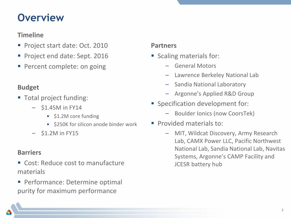
OverviewTimeline Project start date: Oct. 2010 Project end date: Sept. 2016 Percent complete: on going
Budget Total project funding:
– $1.45M in FY14• $1.2M core funding• $250K for silicon anode binder work
– $1.2M in FY15
Barriers Cost: Reduce cost to manufacture materials Performance: Determine optimal purity for maximum performance
Partners Scaling materials for:
– General Motors– Lawrence Berkeley National Lab– Sandia National Laboratory– Argonne’s Applied R&D Group
Specification development for:– Boulder Ionics (now CoorsTek)
Provided materials to:– MIT, Wildcat Discovery, Army Research
Lab, CAMX Power LLC, Pacific Northwest National Lab, Sandia National Lab, Navitas Systems, Argonne’s CAMP Facility and JCESR battery hub
2

Approach - Milestones
FY14 – LBNL-PEFM– LBNL-PFM suite– Li-FSI Impurity study initiated– GM-Polymer initiated– Li-TDI
FY15– Li-FSI Impurity vs. performance study– GM-Polymer– SNL-PFPBO•LiF– Fluorinated EMC initiated– Fluorinated DEC initiated– Si-PFM binder study
FY16– 4-6 Electrolyte materials to be scaled– Develop specifications for battery
grade materials
MILESTONE DATE Complete
GM-Separator
Assess scalability of disclosed process 04/22/14
Develop and validate scalable process chemistry (10g scale) 05/22/14
Process chemistry for base polymer formulations 8/13/14
Go/ No Go GO
First process scale-up (30g bench scale) 9/15/14
Go/ No Go NO GO
Back to GM for further basic R&D
SNL- PFPBO
Assess scalability of disclosed process 9/8/14
Develop and validate scalable process chemistry (10g scale) 11/6/14
Go/ No Go GO
First process scale-up (100g bench scale) 12/1/14
Go/ No Go GO
Second process scale-up (1000g pilot scale) 3/11/15
Li-FSI Impurity Study
Develop analytical methods 12/18/14
Develop spiking procedures 2/6/15
Develop electrochemical formulations 3/6/15
Test electrochemical formulations ongoing
F-EMC
Assess scalability of disclosed process 1/9/15
Develop and validate scalable process chemistry (10g scale) 3/16/15
Go/ No Go GO
First process scale-up (100g bench scale) ongoing
F-DEC
Assess scalability of disclosed process 1/16/15
Develop and validate scalable process chemistry (10g scale) 2/19/15
Go/ No Go GO
First process scale-up (100g bench scale) ongoing
Morphology Study for PFM-Si
Synthesize PFM polymers 1/25/15
Develop blending formulations (25g scale) 4/23/15
3
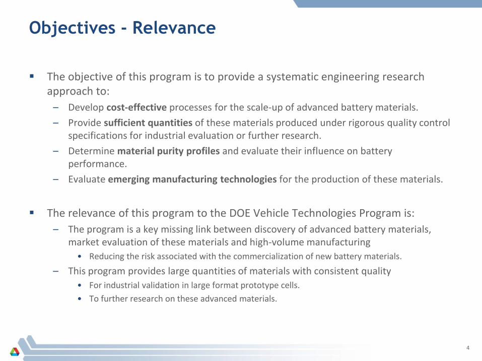
Objectives - Relevance
The objective of this program is to provide a systematic engineering research approach to:
– Develop cost-effective processes for the scale-up of advanced battery materials.– Provide sufficient quantities of these materials produced under rigorous quality control
specifications for industrial evaluation or further research.– Determine material purity profiles and evaluate their influence on battery
performance.– Evaluate emerging manufacturing technologies for the production of these materials.
The relevance of this program to the DOE Vehicle Technologies Program is:– The program is a key missing link between discovery of advanced battery materials,
market evaluation of these materials and high-volume manufacturing• Reducing the risk associated with the commercialization of new battery materials.
– This program provides large quantities of materials with consistent quality• For industrial validation in large format prototype cells.• To further research on these advanced materials.
4
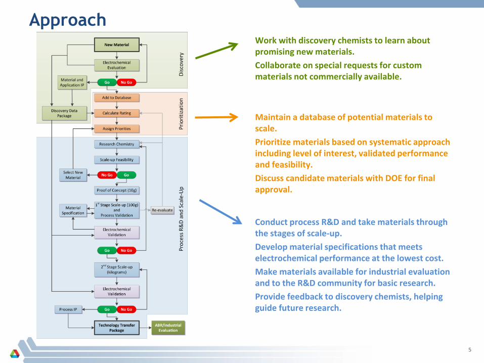
Approach
Conduct process R&D and take materials through the stages of scale-up.Develop material specifications that meets electrochemical performance at the lowest cost.Make materials available for industrial evaluation and to the R&D community for basic research.Provide feedback to discovery chemists, helping guide future research.
Work with discovery chemists to learn about promising new materials.Collaborate on special requests for custom materials not commercially available.
Maintain a database of potential materials to scale.Prioritize materials based on systematic approach including level of interest, validated performance and feasibility.Discuss candidate materials with DOE for final approval.
5
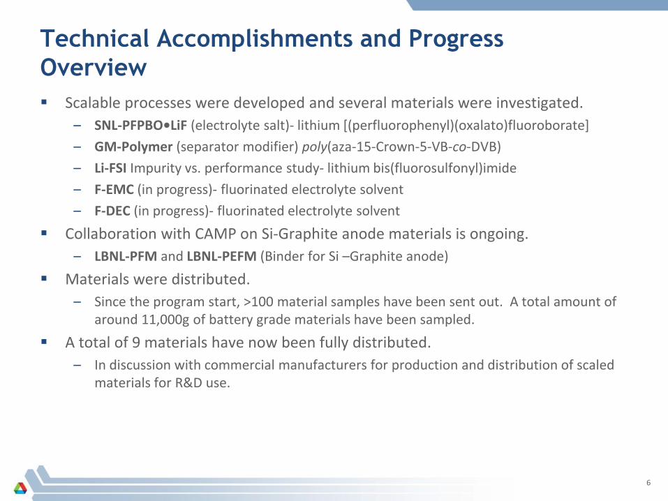
Technical Accomplishments and ProgressOverview Scalable processes were developed and several materials were investigated.
– SNL-PFPBO•LiF (electrolyte salt)- lithium [(perfluorophenyl)(oxalato)fluoroborate]– GM-Polymer (separator modifier) poly(aza-15-Crown-5-VB-co-DVB)– Li-FSI Impurity vs. performance study- lithium bis(fluorosulfonyl)imide– F-EMC (in progress)- fluorinated electrolyte solvent– F-DEC (in progress)- fluorinated electrolyte solvent
Collaboration with CAMP on Si-Graphite anode materials is ongoing.– LBNL-PFM and LBNL-PEFM (Binder for Si –Graphite anode)
Materials were distributed.– Since the program start, >100 material samples have been sent out. A total amount of
around 11,000g of battery grade materials have been sampled.
A total of 9 materials have now been fully distributed. – In discussion with commercial manufacturers for production and distribution of scaled
materials for R&D use.
6
Technical Accomplishments and Progress: Process R&D of SNL- ABA-LiF salt
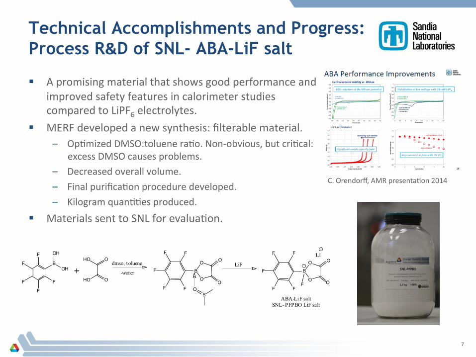
! A promising material that shows good performance and improved safety features in calorimeter studies compared to LiPF6 electrolytes.
! MERF developed a new synthesis: filterable material. – Op,mized DMSO:toluene ra,o. Non-‐obvious, but cri,cal:
excess DMSO causes problems. – Decreased overall volume.
– Final purifica,on procedure developed.
– Kilogram quan,,es produced.
! Materials sent to SNL for evalua,on.
7
C. Orendorff, AMR presenta,on 2014

Technical Accomplishments and Progress: Process R&D of High Voltage Solvents
! Current electrolyte materials fail rapidly at high voltages with 5V LNMO cathode and high energy LMR-‐NMC cathodes.
! Two materials for high voltage electrolytes were added for a good balance of general u,lity, performance, and economy, but are NOT commercially available. – F-‐EMC: trifluoroethyl methyl carbonate
– F-‐DEC: bis(trifluoroethyl) carbonate
! Novel processes have been researched, genera,ng high purity solvents in good yield. Further op,miza,on and scale-‐up work is in progress.
! Materials will be made available to the bacery research community for high voltage programs.
8

Technical Accomplishments and ProgressProcess R&D of GM Separator Modifier
Concept: trap transition metal cations that leach from the positive electrode by using polymeric chelating agents blended with separator material.
New economical process for derivatization of base chloromethyl polymer with aza-15-crown-5 developed.
– The overall process was simplified by reduction of dialysis and freeze-drying steps.
Separator manufacturer required a different polymer morphology for polymer blending.
New cross-linking specifications:– ≥ 95% Conversion from chloromethyl to aza-15-crown-5 – Spherical particle 10-30 nm
MERF prepared several samples with cross-linking ratio of 3% to 40% for analysis.
Cl
n m n m
O
OO
ON
9

Technical Accomplishments and ProgressGM Separator – poly(aza-15-c-5-VB-co-DVB)
Low cross-linking gave good substitution ratios, but poor amorphous morphology.– Unable to formulate blended polymer to form separator.
Higher cross-linking gave good morphology, but left substantial unreacted chloride.– Able to formulate blended polymer, but performance is poor due to chloride.– GM is making progress on a new method to remove residual chloride in the polymers.
The separator manufacturer Entek has been provided samples and has developed a new process for a high loading double sided separator coating.
3% Crosslinking 24% Crosslinking
10
Technical Accomplishments and Progress Si-PFM for Si-Graphite Electrode
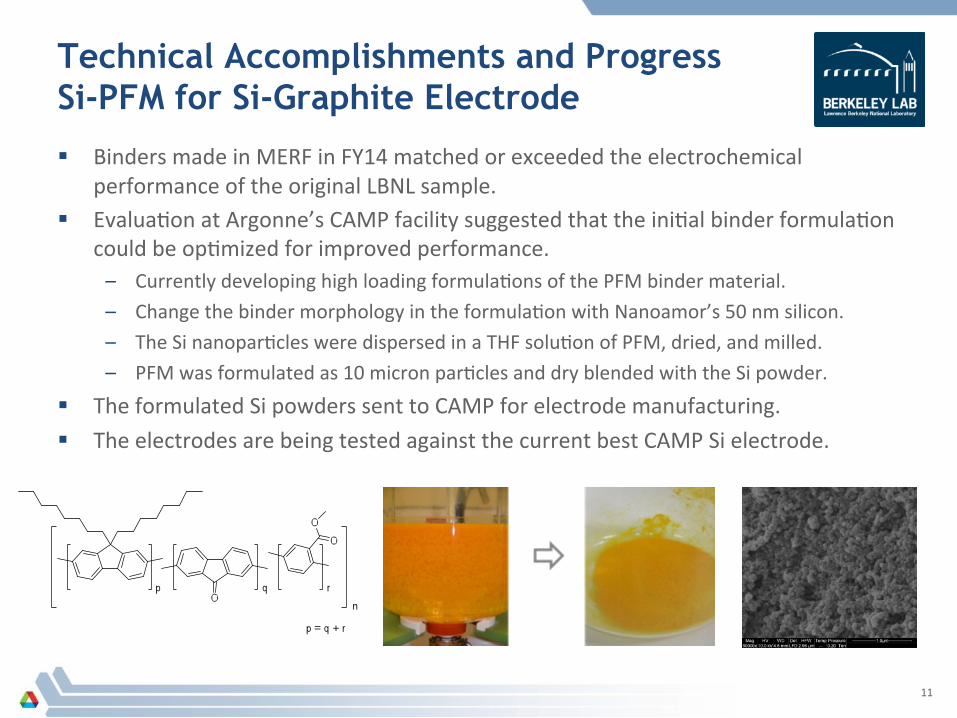
! Binders made in MERF in FY14 matched or exceeded the electrochemical performance of the original LBNL sample.
! Evalua,on at Argonne’s CAMP facility suggested that the ini,al binder formula,on could be op,mized for improved performance. – Currently developing high loading formula,ons of the PFM binder material.
– Change the binder morphology in the formula,on with Nanoamor’s 50 nm silicon.
– The Si nanopar,cles were dispersed in a THF solu,on of PFM, dried, and milled.
– PFM was formulated as 10 micron par,cles and dry blended with the Si powder.
! The formulated Si powders sent to CAMP for electrode manufacturing.
! The electrodes are being tested against the current best CAMP Si electrode.
11

Technical Accomplishments and Progress: Li-FSI Impurity Study: Overview
! Different levels of different electrochemically ac,ve impuri,es could affect the performance of Li-‐FSI as an electrolyte salt for Li-‐ion baceries, genera,ng inconsistent and conflic,ng interpreta,ons of the experimental data.
! Argonne in collabora,on with Boulder Ionics is inves,ga,ng the effects of different impurity profiles on the electrochemical performance of Li-‐FSI.
! We inves,gated the effects of added impuri,es on corrosion, cycle life and calendar life.
12
Boulder Ionics
+
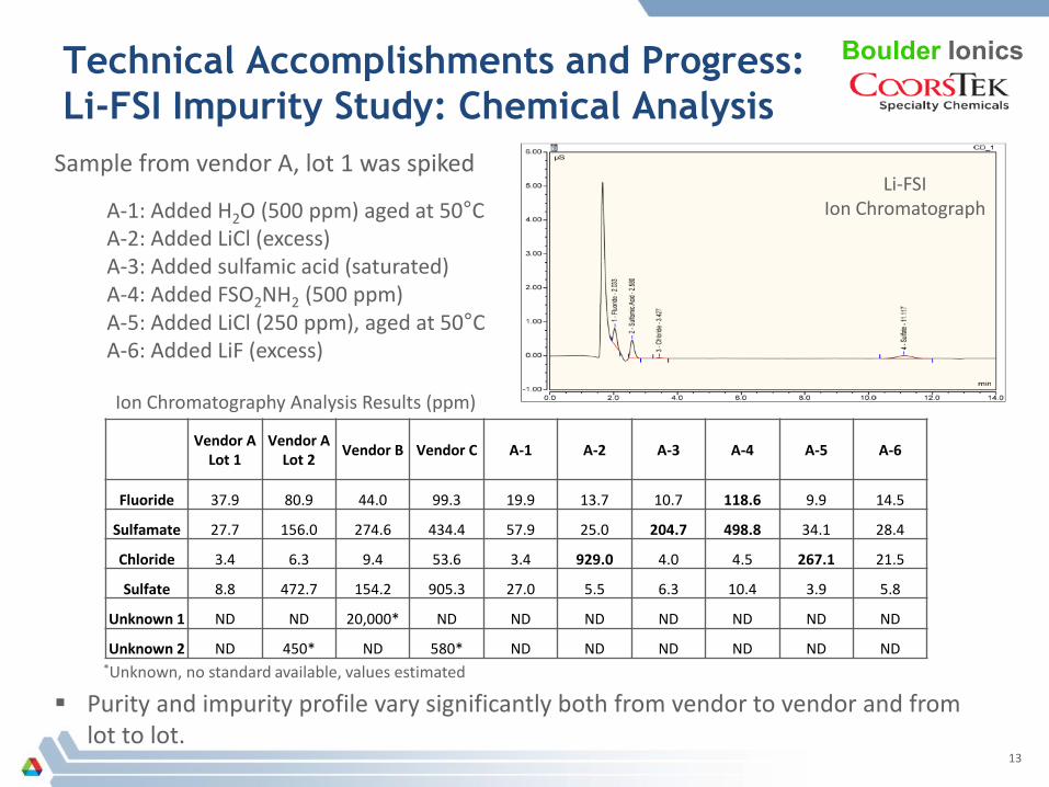
Technical Accomplishments and Progress:Li-FSI Impurity Study: Chemical Analysis
Boulder Ionics
Vendor A Lot 1
Vendor A Lot 2 Vendor B Vendor C A-1 A-2 A-3 A-4 A-5 A-6
Fluoride 37.9 80.9 44.0 99.3 19.9 13.7 10.7 118.6 9.9 14.5
Sulfamate 27.7 156.0 274.6 434.4 57.9 25.0 204.7 498.8 34.1 28.4
Chloride 3.4 6.3 9.4 53.6 3.4 929.0 4.0 4.5 267.1 21.5
Sulfate 8.8 472.7 154.2 905.3 27.0 5.5 6.3 10.4 3.9 5.8
Unknown 1 ND ND 20,000* ND ND ND ND ND ND ND
Unknown 2 ND 450* ND 580* ND ND ND ND ND ND
Ion Chromatography Analysis Results (ppm)
Sample from vendor A, lot 1 was spiked
A-1: Added H2O (500 ppm) aged at 50°CA-2: Added LiCl (excess)A-3: Added sulfamic acid (saturated)A-4: Added FSO2NH2 (500 ppm)A-5: Added LiCl (250 ppm), aged at 50°CA-6: Added LiF (excess)
Li-FSIIon Chromatograph
Purity and impurity profile vary significantly both from vendor to vendor and from lot to lot.
*Unknown, no standard available, values estimated
13
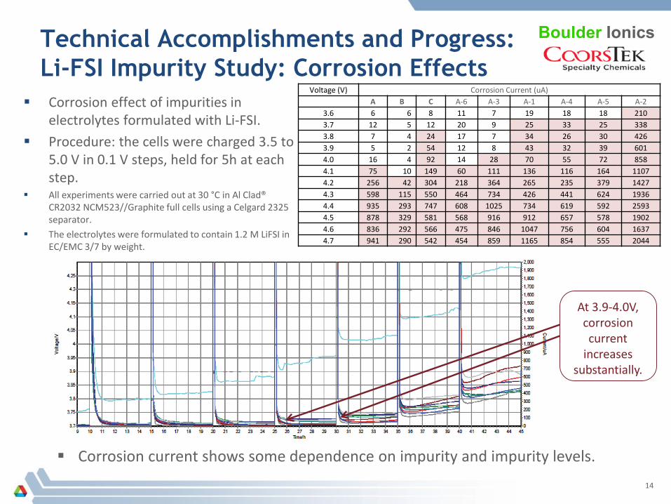
Technical Accomplishments and Progress:Li-FSI Impurity Study: Corrosion Effects
Corrosion effect of impurities in electrolytes formulated with Li-FSI.
Procedure: the cells were charged 3.5 to 5.0 V in 0.1 V steps, held for 5h at each step.
All experiments were carried out at 30 °C in Al Clad® CR2032 NCM523//Graphite full cells using a Celgard 2325 separator.
The electrolytes were formulated to contain 1.2 M LiFSI in EC/EMC 3/7 by weight.
Boulder Ionics
At 3.9-4.0V, corrosion current
increases substantially.
Corrosion current shows some dependence on impurity and impurity levels.
Voltage (V) Corrosion Current (uA)A B C A-6 A-3 A-1 A-4 A-5 A-2
3.6 6 6 8 11 7 19 18 18 2103.7 12 5 12 20 9 25 33 25 3383.8 7 4 24 17 7 34 26 30 4263.9 5 2 54 12 8 43 32 39 6014.0 16 4 92 14 28 70 55 72 8584.1 75 10 149 60 111 136 116 164 11074.2 256 42 304 218 364 265 235 379 14274.3 598 115 550 464 734 426 441 624 19364.4 935 293 747 608 1025 734 619 592 25934.5 878 329 581 568 916 912 657 578 19024.6 836 292 566 475 846 1047 756 604 16374.7 941 290 542 454 859 1165 854 555 2044
14
A5: AddedChloride
Vendor ALot 1
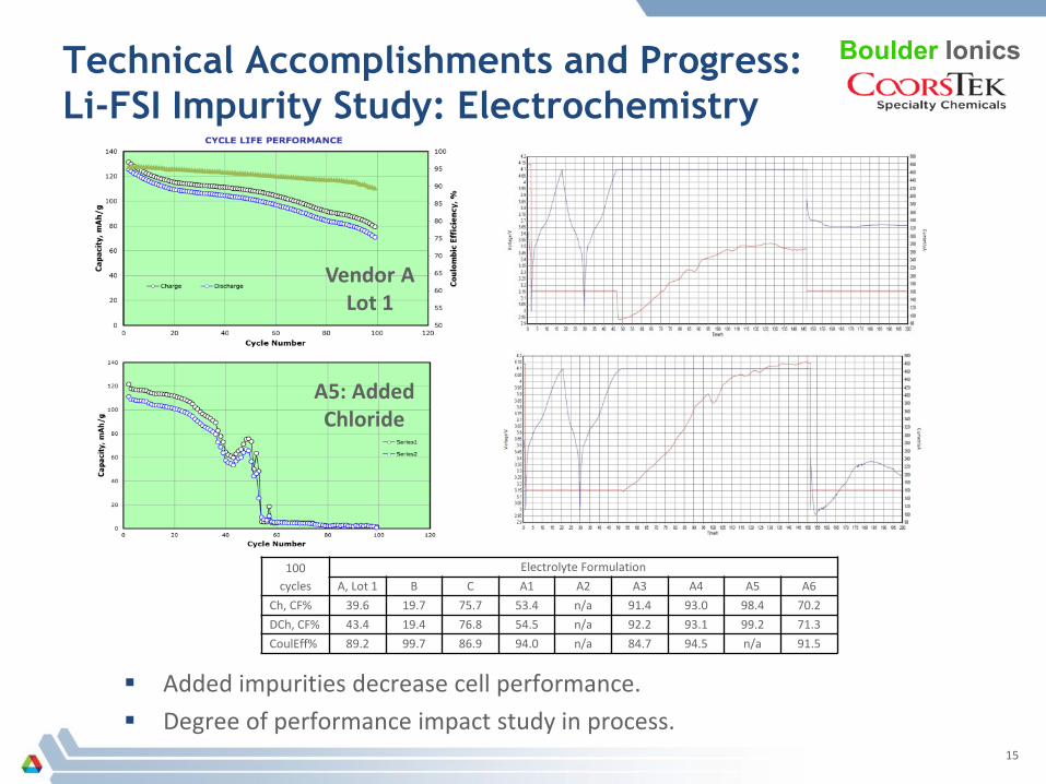
Technical Accomplishments and Progress:Li-FSI Impurity Study: Electrochemistry
Boulder Ionics
100 cycles
Electrolyte FormulationA, Lot 1 B C A1 A2 A3 A4 A5 A6
Ch, CF% 39.6 19.7 75.7 53.4 n/a 91.4 93.0 98.4 70.2DCh, CF% 43.4 19.4 76.8 54.5 n/a 92.2 93.1 99.2 71.3CoulEff% 89.2 99.7 86.9 94.0 n/a 84.7 94.5 n/a 91.5
Added impurities decrease cell performance. Degree of performance impact study in process.
15
Response to Previous Year Reviewer’ Comments “More work needs to be done in prioritizing which chemicals/materials are scaled-up.”
– Response: A new center has recently been established at Argonne referred to as the Argonne Collaborative Center for Energy Storage Sciences (ACCESS). ACCESS will integrate the battery and energy storage work at Argonne through an internal research, development and commercialization team and an external advisory board, composed of experienced members from other national labs, academia and industry. We intend to work through ACCESS to have stakeholders help us gauge and advise on materials selected to scale, resulting in a more robust and transparent process.
“Discuss the relationship between the scale-up and the amount of impurities in the materials produced.”– Response: Our goal to develop economical, industry-ready large-scale processes for battery grade
material frequently requires significant modifications to the original route. Thus, the scale-up material may have a different impurity profile than the bench scale material. We analyze the materials using multiple analytical techniques that often were not used on the bench material. Frequently, we have found that the scaled material is as chemically pure or better that available bench samples. The final test is the electrochemical analysis to evaluate the battery performance.
– The second part is the recognition that different impurities in a material may affect the performance in different ways. This is illustrated by the Li-FSI study to determine the effect of anionic impurities on the battery performance.
– In manufacturing, higher purity materials have a associated higher cost, so developing a complete understanding of the exact purity requirements of battery grade material will result in a lower cost product. For example, some impurities may not have a strong effect on performance, and therefore do not have to be reduced to ultra-low levels, saving the cost of repeated purifications.
16
Collaborations Materials process R&D:
– General Motors (Bob Powell)• Synthesis and characterization of separator modifier
– Sandia National Lab (Chris Orendorff, Kyle Fenton)• Material synthesis and abuse tolerance analysis
– Boulder Ionics (now CoorsTek, Jerry Martin, Andrew Riscoe)• Li-FSI impurity vs performance study
– Lawrence Berkeley National Lab (Gao Liu) and Argonne’s CAMP facility (Andrew Jansen, Bryant Polzin)
• Si-binder synthesis, anode formulation and testing
– Argonne National Lab (John Zhang)• Synthesis of high voltage solvents F-EMC, F-DEC
– JCESR (Tony Burrell)• Novel Mg and Ca salts for beyond Li-ion battery R&D
Material samples provided for further research:• Army Research Lab (Kang Xu)• Pacific Northwest National Lab (Wu Xu)• Navitas Systems (Mike Wixom)• MIT (Fikile Brushett)• JCESR (Lu Zhang)• Wildcat Discovery (Ye Zhu)
Boulder Ionics
17
Remaining Challenges and Barriers
New battery materials are continually being discovered and developed, but industry is typically unable to model the cost of production using bench scale processes and obtain large samples for evaluation.
There is a strong demand from the research community for high quality, uniform experimental materials.
A detailed understanding of impurity profiles of experimental materials used in the battery community is needed, as well as their effect on battery performance.
Battery grade specifications are needed for newly developed battery materials to minimize cost.
Emerging manufacturing technologies need to be evaluated to further reduce production costs of battery materials.
18
Activities for Next Fiscal Year
Manage battery materials database and continue to populate with new candidate materials of interest to the ABR program.
– Rank and prioritize the new materials.
Develop scalable process for 4-6 materials and produce sufficient quantities for sampling.
– Develop scalable process, analytical methods and quality control procedures.– Validate the manufacturing process, analytical and electrochemical properties and
characterize the impurity profile.– Create Technology Transfer Packages for industry.– Supply material samples to the research community and industry for evaluation.
Investigate analytical purity vs. electrochemical performance information for additional materials.
19

Summary This program has been developed to provide a systematic approach to process
R&D and scale-up, and to provide sufficient quantities of advanced battery grade materials for industrial evaluation.
Argonne’s process R&D program enables industry to carry out large-scale testing of new battery materials and enable scientists to obtain consistent quality, next generation materials for further research.
Integration of materials discovery with process R&D will expedite the time needed for commercial deployment.
Over 100 samples have been presented to collaborating research entities.– Several materials have been fully distributed.– In discussions with commercial manufacturers for production
and distribution of scaled materials for R&D use.
Technical Summary:– Completed LBNL-Si anode binder material.– Completed SNL- ABA-LiF salt.– Identified scale-up issue with GM material, sent back for further basic research. – Performance of Li-FSI can be correlated to the levels of anion impurities in the material.– Work on several new fluorinated solvents for HV electrolytes is underway.
20
Acknowledgements and Contributors
Argonne National Laboratory– Tony Burrell– Ira Bloom– John Zhang– Daniel Abraham– Wenquan Lu– Andrew Jansen– Brian Polzin– Steven Trask– Gerald Jeka– Mike Kras– Chris Claxton
Lawrence Berkeley National Laboratory– Gao Liu
Pacific Northwest National Laboratory– Wesley Henderson– Wu Xu
Sandia National Laboratory– Chris Orendorff– Kyle Fenton
General Motors– Bob Powell– Ion Halalay
Boulder Ionics– Jerry Martin– Andrew Riscoe
Support from David Howell and Peter Faguy of the U.S. Department of Energy’s Office of Vehicle Technologies is gratefully acknowledged.
For samples and further information:
www.anl.gov/merf21
Technical Backup Slides
22

Technical Accomplishments and ProgressSi-PFM for Si-Graphite Electrode: Wet Blending
PFM was dissolved in THF (1/100 w/v). Silicon nanoparticles were added (Si/PFM 9/1 w/w) and vacuum dried at 30°C. Material was ball milled to yield a multimodal PSD. Material forwarded to CAMP.
Nanoamor’s 50 nm silicon coated with 10% w/w PFM (before milling)
PFM polymer, lot KP03080Mw = 47,000 Da, PDI = 2.1
PSA of Si-PFM after milling23

Technical Accomplishments and ProgressSi-PFM for Si-Graphite Electrode: Dry Blending
High dilution PFM solution (1/350 w/v) in THF was added to excess methanol. Organic solvents were replaced with water and the suspension was freeze-dried. Uniform PFM particles dry blended 1:9 with Nanoamor Si giving a bimodal PSD.
PSA of Si-PFM after blending
SEM images of freeze-dried PFM powder24
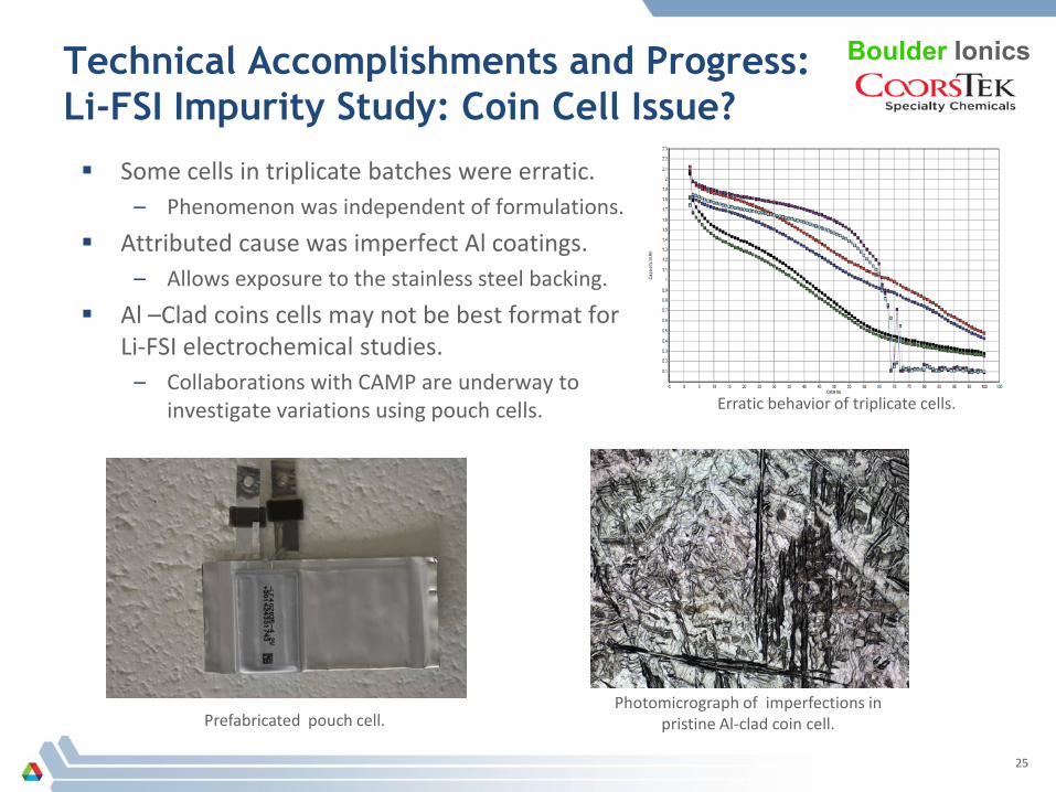
Technical Accomplishments and Progress:Li-FSI Impurity Study: Coin Cell Issue?
Boulder Ionics
Erratic behavior of triplicate cells.
Photomicrograph of imperfections in pristine Al-clad coin cell.
Some cells in triplicate batches were erratic.– Phenomenon was independent of formulations.
Attributed cause was imperfect Al coatings.– Allows exposure to the stainless steel backing.
Al –Clad coins cells may not be best format for Li-FSI electrochemical studies.
– Collaborations with CAMP are underway to investigate variations using pouch cells.
Prefabricated pouch cell.
25
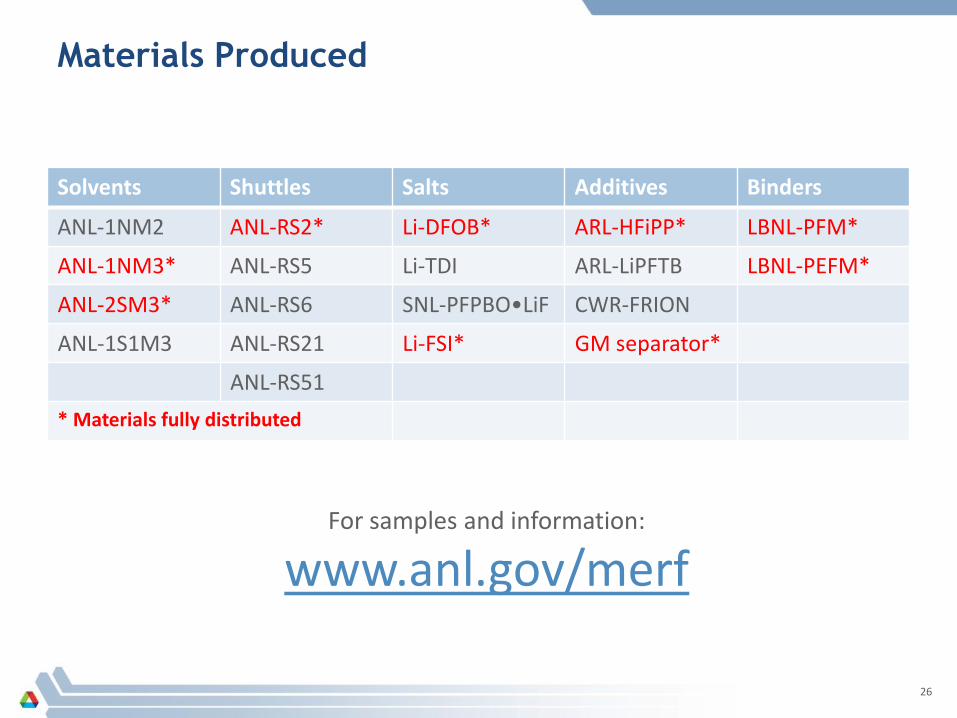
Materials Produced
Solvents Shuttles Salts Additives Binders
ANL-1NM2 ANL-RS2* Li-DFOB* ARL-HFiPP* LBNL-PFM*
ANL-1NM3* ANL-RS5 Li-TDI ARL-LiPFTB LBNL-PEFM*
ANL-2SM3* ANL-RS6 SNL-PFPBO•LiF CWR-FRION
ANL-1S1M3 ANL-RS21 Li-FSI* GM separator*
ANL-RS51* Materials fully distributed
For samples and information:
www.anl.gov/merf
26


