
P R O D U C T D ATA
The NEXUS Range of Conditioning Amplifiers Types 2690, 2691, 2692 and 2693
The NEXUS™ concept is based on flexibility. A single mainframe, avariety of input and output channels, and different filter optionsmake the system highly customizable, as you can configure yourconditioning amplifier to suit your needs. You can have acousticand vibration inputs in the same mainframe with one, two, three orfour independent input channels.
The NEXUS units you already own can also be reconfigured if yourrequirements change. For example, if you have a 1-channel chargeconditioning amplifier, it can be upgraded to a 2-channel charge/2-channel microphone conditioning amplifier. In addition, a selectionof optional filters can be installed in each channel module uponrequest.
Microprocessors are used for control, display and interfacingpurposes, but the signal is analogue to obtain optimum signal/noise ratio and the lowest possible distortion. NEXUS supportstransducers with transducer electronic data sheets (TEDS)according to IEEE 1451.4.
Uses And Features
Uses• Specially suited for automotive use. Developed in association
with major car manufacturers, for high-quality field andlaboratory measurement systems
• For use with charge accelerometers, hydrophones, forcetransducers, condenser microphones, CCLD* accelerometers,CCLD preamplifiers, voltage input and sound intensity probes
• Field recording of vibration and acoustic signals • Specially suitable for applications where shocks and impulses
occur such as gas turbine testing and munitions testing (Types2692-C and -D only)
Features• Highly flexible construction: 1-, 2-, 3- or 4-channel
configurations that can be a combination of acoustic and/orvibration transducer inputs with different filter options
• High input signal range, low noise and extensive overloadfacilities
• Supports transducers with TEDS according to IEEE 1451.4• Available for: charge, microphone, sound intensity, CCLD and
very high input• Compact robust design and battery operation makes it also
suitable for use in the field• Serial control interface (RS–232) allows for computer control of
set-up and test functions. A large number of amplifiers can becontrolled from a single PC
• High accuracy due to reliable construction and a wide range ofcalibration options. Patented Charge Injection Calibration (CIC)and the patented Mounted Resonance Test (MRT) are built-in
• Wide range of filters that can be set up for specific tasks• Rack-mounting frames available* CCLD: Constant current line drive, also known as DeltaTron (IEPE compatible)

Reliable Design
To survive the harsh electrical environment in cars, NEXUS conditioning amplifiers have specifications thatfar exceed the strict European EMC immunity requirements. ISO 7637-1 “Road Vehicles – Electricaldisturbance by conduction and coupling” requirements are met. Mechanical robustness is equally high andmeets MIL–STD–810C and IEC 60068–2–6 standards.
EnvironmentalSince all NEXUS amplifiers are built for portable outdoor use, they meet strict requirements fortemperature and humidity. The operating temperature range extends from –10 to +55 °C (14 to 131 °F).The instrument will withstand rain if kept with the front panel facing upwards. However, because of thesockets on the back panel it is not watertight.
Modular Flexibility
All NEXUS conditioning amplifiers use the same mainframe and power supply hardware, while the channelconfiguration is based on interchangeable modules. This modular design gives the amplifiers a high degreeof flexibility with regards to design. To reduce the cost of the instrument and to ensure accuracy andreliability, modules must be replaced at Brüel & Kjær.
Fig. 1 Modular design of NEXUS conditioning amplifiers
990186
OVL
Ch: 1 2 3 4
Battery
Back panel
Optionalmodule
Motherboard
DisplayControl panel
Processorand power
module
2
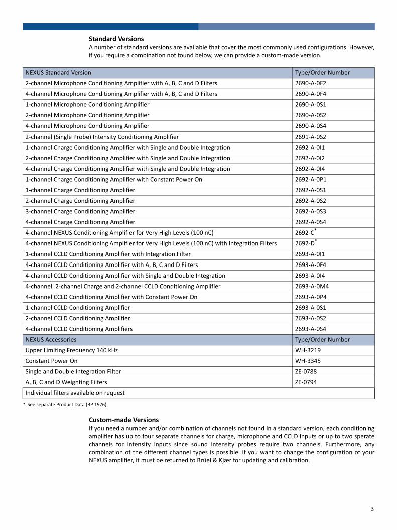
Standard VersionsA number of standard versions are available that cover the most commonly used configurations. However,if you require a combination not found below, we can provide a custom-made version.
Custom-made VersionsIf you need a number and/or combination of channels not found in a standard version, each conditioningamplifier has up to four separate channels for charge, microphone and CCLD inputs or up to two speratechannels for intensity inputs since sound intensity probes require two channels. Furthermore, anycombination of the different channel types is possible. If you want to change the configuration of yourNEXUS amplifier, it must be returned to Brüel & Kjær for updating and calibration.
NEXUS Standard Version Type/Order Number
2-channel Microphone Conditioning Amplifier with A, B, C and D Filters 2690-A-0F2
4-channel Microphone Conditioning Amplifier with A, B, C and D Filters 2690-A-0F4
1-channel Microphone Conditioning Amplifier 2690-A-0S1
2-channel Microphone Conditioning Amplifier 2690-A-0S2
4-channel Microphone Conditioning Amplifier 2690-A-0S4
2-channel (Single Probe) Intensity Conditioning Amplifier 2691-A-0S2
1-channel Charge Conditioning Amplifier with Single and Double Integration 2692-A-0I1
2-channel Charge Conditioning Amplifier with Single and Double Integration 2692-A-0I2
4-channel Charge Conditioning Amplifier with Single and Double Integration 2692-A-0I4
1-channel Charge Conditioning Amplifier with Constant Power On 2692-A-0P1
1-channel Charge Conditioning Amplifier 2692-A-0S1
2-channel Charge Conditioning Amplifier 2692-A-0S2
3-channel Charge Conditioning Amplifier 2692-A-0S3
4-channel Charge Conditioning Amplifier 2692-A-0S4
4-channel NEXUS Conditioning Amplifier for Very High Levels (100 nC) 2692-C*
4-channel NEXUS Conditioning Amplifier for Very High Levels (100 nC) with Integration Filters 2692-D*
1-channel CCLD Conditioning Amplifier with Integration Filter 2693-A-0I1
4-channel CCLD Conditioning Amplifier with A, B, C and D Filters 2693-A-0F4
4-channel CCLD Conditioning Amplifier with Single and Double Integration 2693-A-0I4
4-channel, 2-channel Charge and 2-channel CCLD Conditioning Amplifier 2693-A-0M4
4-channel CCLD Conditioning Amplifier with Constant Power On 2693-A-0P4
1-channel CCLD Conditioning Amplifier 2693-A-0S1
2-channel CCLD Conditioning Amplifier 2693-A-0S2
4-channel CCLD Conditioning Amplifiers 2693-A-0S4
NEXUS Accessories Type/Order Number
Upper Limiting Frequency 140 kHz WH-3219
Constant Power On WH-3345
Single and Double Integration Filter ZE-0788
A, B, C and D Weighting Filters ZE-0794
Individual filters available on request
* See separate Product Data (BP 1976)
3
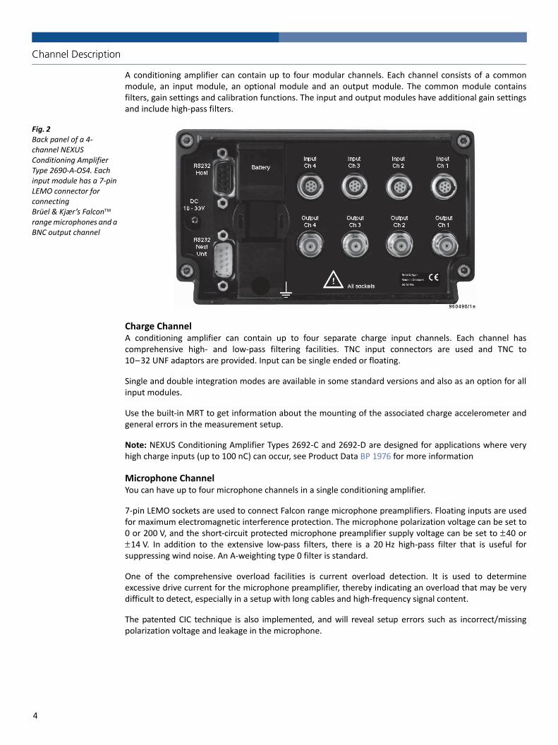
Channel Description
A conditioning amplifier can contain up to four modular channels. Each channel consists of a commonmodule, an input module, an optional module and an output module. The common module containsfilters, gain settings and calibration functions. The input and output modules have additional gain settingsand include high-pass filters.
Fig. 2 Back panel of a 4-channel NEXUS Conditioning Amplifier Type 2690-A-OS4. Each input module has a 7-pin LEMO connector for connecting Brüel & Kjær’s Falcon range microphones and a BNC output channel
Charge ChannelA conditioning amplifier can contain up to four separate charge input channels. Each channel hascomprehensive high- and low-pass filtering facilities. TNC input connectors are used and TNC to10–32 UNF adaptors are provided. Input can be single ended or floating.
Single and double integration modes are available in some standard versions and also as an option for allinput modules.
Use the built-in MRT to get information about the mounting of the associated charge accelerometer andgeneral errors in the measurement setup.
Note: NEXUS Conditioning Amplifier Types 2692-C and 2692-D are designed for applications where veryhigh charge inputs (up to 100 nC) can occur, see Product Data BP 1976 for more information
Microphone ChannelYou can have up to four microphone channels in a single conditioning amplifier.
7-pin LEMO sockets are used to connect Falcon range microphone preamplifiers. Floating inputs are usedfor maximum electromagnetic interference protection. The microphone polarization voltage can be set to0 or 200 V, and the short-circuit protected microphone preamplifier supply voltage can be set to ±40 or±14 V. In addition to the extensive low-pass filters, there is a 20 Hz high-pass filter that is useful forsuppressing wind noise. An A-weighting type 0 filter is standard.
One of the comprehensive overload facilities is current overload detection. It is used to determineexcessive drive current for the microphone preamplifier, thereby indicating an overload that may be verydifficult to detect, especially in a setup with long cables and high-frequency signal content.
The patented CIC technique is also implemented, and will reveal setup errors such as incorrect/missingpolarization voltage and leakage in the microphone.
4

Sound Intensity ChannelOne or two sound intensity probes can be connected with 7-pin LEMO connectors in a single conditioningamplifier containing two or four intensity channels.
The features of the sound intensity channel are very similar to the microphone channel, but it hasIEC 61043 standard Class 1 and ANSI S1.9–1996 Class 1 phase- and gain-match specifications using thespecial intensity 20 Hz high-pass filter.
CCLD ChannelUp to four CCLD input modules can be fitted for conditioning of input signals from CCLD basedaccelerometers, microphone preamplifiers or direct voltage input.
The input BNT socket can be floating or single-ended. A constant current of 4 or 10 mA is supplied in theCCLD mode. It also supplies an 8 V DC voltage on the inner screen of the TNC socket for connecting a tachoprobe.
The current overload detection circuit, similar to the one used for microphone input modules, has beenimplemented.
Reference and Test GeneratorsA reference generator is available with all channel types and can be used as an excitation signal for yourmeasurement setup. The output signal is a sinusoidal signal with 1 V RMS level. For charge channels a testtone is also available. It is a 159.2 Hz (±1%) sinusoidal signal which is applied in parallel with the chargeinput signal.
Output ModuleFor all channels, the output module will drive 20 m of cable to 100 kHz, 100 m of cable (100 pF/m) to20 kHz or 1000 m to 2 kHz. A BNC connector is used, and you can select single-ended or floating mode.The output is protected against short-circuits and voltage overload, even if instrument is switched off.
Flexible Filter Configuration
Built-in FiltersA number of filters are available as standard within NEXUS. The filters are low-pass filters with cut-offfrequencies of 0.1, 1, 3, 10, 22.4, 30 and 100 kHz (40 dB/decade), high-pass filters with 0.1, 1, 10 and 20 Hzcut-off frequencies (10, 20 Hz/80 dB/decade), A-weighting for microphone/intensity channels and a 20 Hz/40 dB/decade intensity filter for intensity channels.
Optional FiltersIn addition to the built-in filters, a number of optional standard filters can be installed upon request, forexample A-, B-, C- and D-weighting and single/double integration. User-defined filters can be made onspecial request. Note that for embedded software versions greater than 1.2, there are no restrictions onthe use of the optional filters in conjunction with the built-in standard high- and low-pass filters.
5
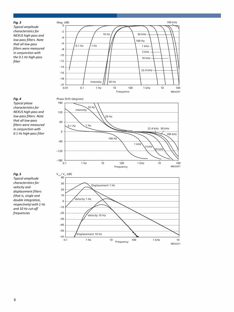
Fig. 3 Typical amplitude characteristics for NEXUS high-pass and low-pass filters. Note that all low-pass filters were measured in conjunction with the 0.1 Hz high-pass filter
Fig. 4 Typical phase characteristics for NEXUS high-pass and low-pass filters. Note that all low-pass filters were measured in conjunction with 0.1 Hz high-pass filter
Fig. 5 Typical amplitude characteristics for velocity and displacement filters (that is, single and double integration, respectively) with 1 Hz and 10 Hz cut-off frequencies
0Mag. (dB)
–2
0.1 Hz 1 Hz 1 kHz
3 kHz
30 kHz
22.4 kHz
100 Hz
100 kHz
20 Hz
10 Hz
10 kHz
980329/1
Intensity
–4
–6
–8
–10
–12
–14
–16
–18
–200.01 0.1 1 Hz 10 100 1 kHz 10 100
Frequency
180
120
60
0
–60
0.1 Hz 1 Hz
20 Hz
100 Hz
1 kHz3 kHz
10 kHz
100 kHz
22.4 kHz 30 kHz
Intensity10 Hz
–120
–180
Phase Shift (degrees)
980330/10.1 1 Hz 10 100 1 kHz 10 100
Frequency
40Vout / Vin (dB)
30Displacement 1 Hz
Displacement 10 Hz
Velocity 1 Hz
Velocity 10 Hz
980332/1
20
10
0
–10
–20
–30
–40
–50
–600.1 1 Hz 10
Frequency100 1 kHz 10
6
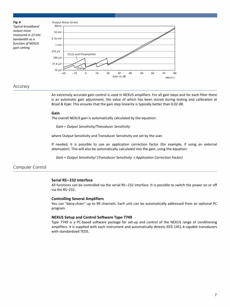
Fig. 6 Typical broadband output noise measured in 22 kHz bandwidth as a function of NEXUS gain setting
Accuracy
An extremely accurate gain control is used in NEXUS amplifiers. For all gain steps and for each filter thereis an automatic gain adjustment, the value of which has been stored during testing and calibration atBrüel & Kjær. This ensures that the gain step linearity is typically better than 0.02 dB.
GainThe overall NEXUS gain is automatically calculated by the equation:
Gain = Output Sensitivity/Transducer Sensitivity
where Output Sensitivity and Transducer Sensitivity are set by the user.
If needed, it is possible to use an application correction factor (for example, if using an externalattenuator). This will also be automatically calculated into the gain, using the equation:
Gain = Output Sensitivity/ (Transducer Sensitivity × Application Correction Factor)
Computer Control
Serial RS–232 InterfaceAll functions can be controlled via the serial RS–232 interface. It is possible to switch the power on or offvia the RS–232.
Controlling Several AmplifiersYou can “daisy-chain” up to 99 channels. Each unit can be automatically addressed from an optional PCprogram.
NEXUS Setup and Control Software Type 7749Type 7749 is a PC-based software package for set-up and control of the NEXUS range of conditioningamplifiers. It is supplied with each instrument and automatically detects IEEE 1451.4 capable transducerswith standardized TEDS.
30mV
10 mV
3.16 mV
1 mV
316 μV
100 μV
31.6 μV
10 μV
980331/1
–20 –10
CCLD and Preamplifier
Charge
0 10 20 30Gain in dB
40 50 60 70 80
Output Noise (Vrms)
7
Human Interface
Six pushkeys – nothing more is required to set up all parameters from the associated menus:• Amplifier Setup: Set up filters and gain for each individual channel. Also displays information about battery
capacity and overload condition• Transducer Setup: Select transducer type and entering calibrated sensitivity• Transducer Supply: Set up current supply, preamplifier/polarization voltages and cable length• Floating/Correction: Select floating input/output and for entering application corrections• Store/Recall Setup: Store/retrieve of five user-defined setups• Display Setup: Switch back-lighting on/off and adjusting the display contrast• Transducer Test/Ref. Sig.: Select test or reference signals and CIC and MRT parameters• Battery Setup: Read out status on battery charge condition and number of charging cycles• Serial Interface: Set up RS–232 parameters• Self-test: Test the digital hardware
Intelligent Battery
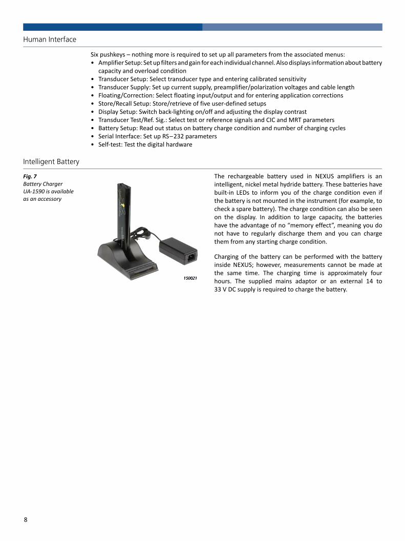
Fig. 7 Battery Charger UA-1590 is available as an accessory
The rechargeable battery used in NEXUS amplifiers is anintelligent, nickel metal hydride battery. These batteries havebuilt-in LEDs to inform you of the charge condition even ifthe battery is not mounted in the instrument (for example, tocheck a spare battery). The charge condition can also be seenon the display. In addition to large capacity, the batterieshave the advantage of no “memory effect”, meaning you donot have to regularly discharge them and you can chargethem from any starting charge condition.
Charging of the battery can be performed with the batteryinside NEXUS; however, measurements cannot be made atthe same time. The charging time is approximately fourhours. The supplied mains adaptor or an external 14 to33 V DC supply is required to charge the battery.
8
Transducer Testing
Overload DetectionAll types of overload are indicated on the front panel LEDs. If you select the relevant menu you can getinformation about the type of overload on the display, or you can get the data via the RS–232 interface.
Comprehensive overload detection facilities are built into the conditioning amplifier: transducer currentoverload (CCLD and microphones), transducer voltage overload (CCLD), common mode input overload,signal overload and common mode output overload.
Peak MeterA peak level meter allows you to monitor the instantaneous peak values for all channels and the maximumpeak values (peak hold) since they were reset. Overload indications are also shown in this menu.
Charge Injection Calibration (CIC)The patented Charge Injection Calibration technique makes it possible to remotely verify the condition ofthe entire measurement setup including the microphone. Available on microphone channels only.
Mounted Resonance Test (MRT)This is another patented Brüel & Kjær technique used to get information about the accelerometermounting and verify that the cable connections are in working order. A short voltage pulse is used to excitethe transducer. The amplifier switches to a measurement mode, measures the resonance frequency andregisters it on the display. MRT works with a number of Brüel & Kjær charge accelerometers that have aresonance frequency between 3 and 40 kHz. Available on charge channels only.
Support of Transducers with TEDS according to IEEE 1451.4
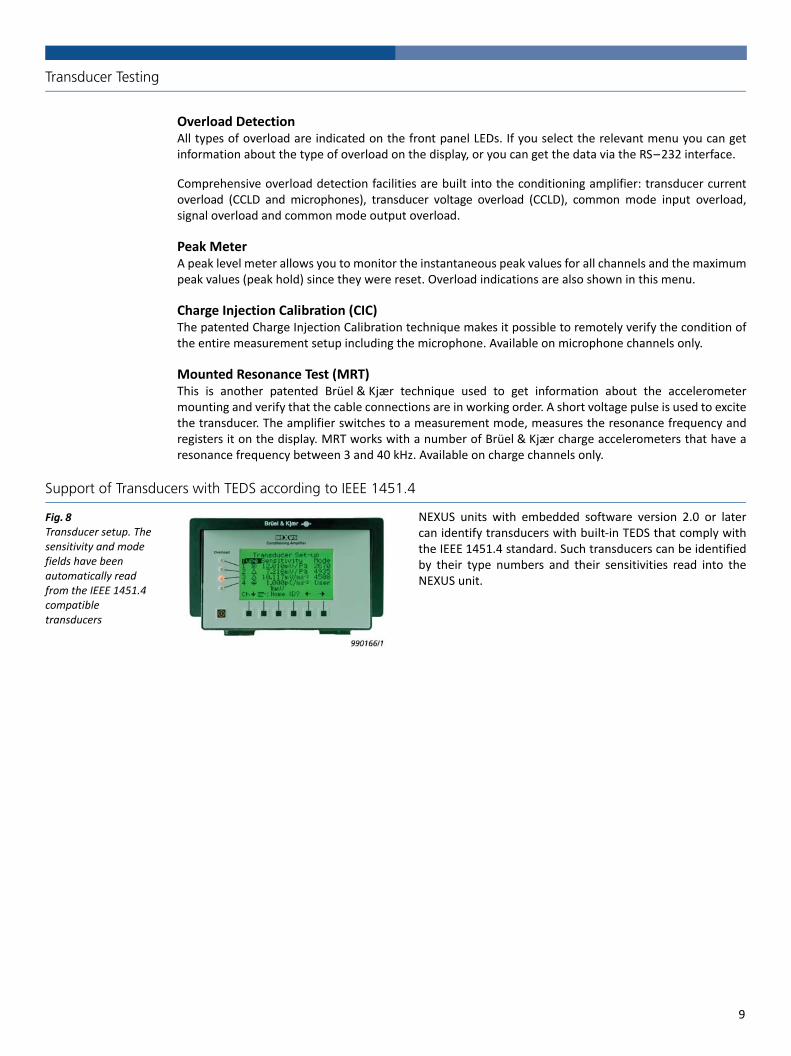
Fig. 8 Transducer setup. The sensitivity and mode fields have been automatically read from the IEEE 1451.4 compatible transducers
NEXUS units with embedded software version 2.0 or latercan identify transducers with built-in TEDS that comply withthe IEEE 1451.4 standard. Such transducers can be identifiedby their type numbers and their sensitivities read into theNEXUS unit.
9
Selected NEXUS Transducers and Accessories
LEMO
DC Power Cable viaCigarette Lighter
AO-05463 m
Powering
Nickel-Metal HydrideRechargeable Battery
QB-0048
LEMO
Mains AdaptorZG-0426
(included with NEXUS)
Fast BatteryCharger Kit
UA-1590
Brüel & KjærType 2671
No. 2125206
Brüel & KjærType 4935
No. 2126352
CCLD Input
Array Mic. 4935
MiniatureAccel. 4507/08
Accelerometer4506
Magnetic TransducerMM-0002
MicrodotMicrodot
AO-0531
AO-1382
BNCBNCAO-0426
AO-0564, 1 – 30 mSMB
AO-0526, 1 – 50 m
1/2“ Prepolarized CCLD Mic. Preamp. 2671
JP-0145
Double Screen Cable, 0.2 – 100 m
Double Screen Cable, 0.3 – 30 m
Double Screen Cable, 0.5 – 100 m
Photoelectric Probes MM-0024
BNTBNTAO-0158, 3 m
Intensity Input
Sound Intensity Probe 3595
AO-0441, 10-pin LEMO to 10-pin LEMO,
1.5 – 170 m
Dual Preamp. 2683and Mic. Pair 4197
7-pinLEMO
JP-1040,2 x 7-pin LEMO
10-pinLEMOJP-1040
10-pinLEMO
AO-0441
1/2“ Mic. Preamp.2669-L, 2673
AO-0537, 0.3 – 150 m
Microphone Input
1/2” Mic. Preamp.2669-B
1/4” Mic. Preamp.2633
1/2” Mic. Preamp.2639
1/2“ Mic. Preamp.2669-C
AO-0428 (included with 2669-B), 3 m
1/4” Mic. Preamp.2670
WL-1260, 0.25 m
7-pin LEMO
AO-0414, 0.5 – 180 m
AO-0419, 0.8 – 180 m
AO-0419, 0.8 – 180 m
Probe Mic. 4182with adaptorZG-0350
Hydrophone 8106AO-0390, 1 – 150 m
Brüel & KjærType 2669
Serial No. 1234567
Brüel & KjærType 2639
Brüel & KjærType 2669 LNo. 212xxxxx
Brüel & KjærType 2669
Serial No. 1234567
Brüel & KjærType 2670
No. 212xxxx
Brüel & KjærType 2670
No. 212xxxx
Charge Input
Hydrophone8103
Accelerometer4393
MicrodotMicrodot
Microdot
Double Screen Cable, 0.1 – 30 m
TNC0.6 – 50 m
10 mTNC
TNCAO-1381
Hydrophone8104
10 mTNC
BNC
JP-0226
JP-0162
JP-0162
JP-0226
BNCHydrophone8105
NEXUS Control Software 7749
Software
Conditioning Amplifier
NEXUS
Brüel B K7/6-'89& Kjær
OverloadCh.1234
Out Unit10 U/Pa
3.16 V/ms-2
1 V/ms-2
316 V/ms-2
NEXUS Conditioning Amplifier
140279
Adaptor
UL-0250
RS-232 to USB
10
Compliance with Standards
The CE marking is the manufacturer's declaration that the product meets the requirements of the applicable EU directivesRCM mark indicates compliance with applicable ACMA technical standards – that is, for telecommunications, radio communications, EMC and EMEChina RoHS mark indicates, that the Environment Friendly Use Period (EFUP) is 25 years according to the Ministry of Information Industries of the People’s Republic of ChinaWEEE mark indicates compliance with the EU WEEE Directive
Safety EN/IEC 61010–1: Safety requirements for electrical equipment for measurement, control and laboratory use.ANSI/UL 61010–1: Safety requirements for electrical equipment for measurement, control and laboratory use
EMC Emission EN/IEC 61000–6–3: Generic emission standard for residential, commercial and light industrial environments.EN/IEC 61000–6–4: Generic emission standard for industrial environments.EN/IEC 61326-1: Electrical equipment for measurement, control and laboratory use - EMC requirementsCISPR 22: Radio disturbance characteristics of information technology equipment. Class B Limits.
EMC Immunity EN/IEC61000–6–1: Generic standards – Immunity for residential, commercial and light industrial environments.EN/IEC 61000–6–2: Generic standards – Immunity for industrial environments.EN/IEC 61326-1: Electrical equipment for measurement, control and laboratory use - EMC requirements.ISO 7637 – 1, 7637 – 2 and 7637 – 3: Road Vehicles – Electrical Disturbance by Conduction and Coupling.Note 1: Refer to “Environmental Susceptibility” in specifications.Note 2: The above is guaranteed using the accessories in this Product Data only.
Temperature IEC 60068–2–1 & IEC 60068–2–2: Environmental Testing. Cold and Dry Heat.Operating Temperature: –10 to +55 °C (14 to 131 °F)Storage Temperature: –25 to +70 °C (–13 to +158 °F)IEC 60068 – 2 – 14: Change of Temperature: –10 to + 55 °C (2 cycles, 1 °C/min.)
Humidity IEC 60068–2–78: Damp Heat: 90% RH (non-condensing at 40 °C (104 °F))Mechanical Operating (peak values):
MIL–STD – 810C: Vibration: 12.7 mm, 15 m/s2, 5 – 500 HzNon-operating:IEC 60068–2–6: Vibration: 0.3 mm, 20 m/s2, 10 – 500 HzIEC 60068–2–27: Shock: 1000 m/s2
IEC 60068–2–29: Bump: 1000 bumps at 250 m/s2
Enclosure IEC 60529: Protection provided by enclosures: IP 43
11
Input Specifications – NEXUS Conditioning Amplifier Types 2690 to 2693
For Specifications on Types 2692-C and 2692-D, see Product Data BP 1976.
Charge Input
Connector: TNCGrounding: Single-ended or floating
MAXIMUM INPUTDifferential Charge: 10 nC (peak)Common Mode Voltage: 4.2 V (peak)At gain ≥ 0.316 mV/pC (–10 dB gain with 1 nF transducer capacitance)
INPUT PROTECTIONDifferential Charge: ≤300 nC (peak)Common Mode Voltage: ≤15 V (peak)
COMMON MODE REJECTION RATIO>50 dB (typical) (50 to 60 Hz with 1 nF transducer capacitance)
AMPLIFIER GAIN0.1 mV/pC to 10 V/pC (–20 to +80 dB gain with 1 nF transducer capacity, +80 dB only recommended with 10 Hz LP-filter selected)
TRANSDUCER SENSITIVITY RANGE10–19 to 10–6 C/MU(MU = mechanical units: m/s2, g, N, Pa)
CALIBRATED OUTPUTSelectable in 10 dB steps. 100 dB attenuator range, 10–13 to 107 V/MU±1% for 0 °C ≤ Ta ≤ +40 °C and ±2% for –10 °C ≤ Ta ≤ +55 °CFrequency range from 5 × fl to 0.2 × fu, wherefl = lower freq. limit: 0.1, 1.0 or 10 Hz andfu = upper freq. limit: 0.1, 1, 3, 10, 30 or 100 kHz
FREQUENCY RANGE (–10%)Acceleration: 0.1 Hz to 100 kHz (transducer cable length <10 m) Velocity (optional): 1.0 Hz to 10 kHzDisplacement (optional): 1.0 Hz to 1 kHz
LOW-PASS FILTER (–10%)0.1, 1, 3, 10, 22.4, 30 or 100 kHz, attenuation slope 40 dB/decade
HIGH-PASS FILTER (–10%)Acceleration: 0.1, 1.0 or 10 HzVelocity (optional): 1.0 or 10 HzDisplacement (optional): 1.0 or 10 Hz
INHERENT NOISE (2 Hz to 22.4 kHz)<5 fC referred to input, –10 °C ≤ Ta ≤+40 °C<10 fC referred to input, 40 °C ≤ Ta ≤+55 °C(amplifier sensitivity (>20 dB) with 1 nF transducer capacitance)
HARMONIC DISTORTION AND NOISE (2 Hz to 22.4 kHz, Qin ≤2 nC peak, Vout ≤3.16 V peak)<0.01% for amplifier gain ≤0.1 V/pC(<40 dB gain with 1 nF transducer capacitance)
ENVIRONMENTAL SUSCEPTIBILITY (referred to input)Magnetic Field: <0.2 fC/(A/m)Electromagnetic Field: <20 fC/(V/m) or <4 fC/VVibration (10 to 500 Hz): <30 fC/(m/s2)
MOUNTED RESONANCE TESTING (MRT)*
Mounted resonance testing of the accelerometer and cable interconnection, controllable from front panel and RS–232 interface
TEST TONE OSCILLATORω = 1000 rad/s (159.2 Hz), sinusoidalTest Level: 1 mV to 10 V (±1%). Controllable from front panel and RS–232 interfaceReference Tone: 1 V (RMS), (±1%), 159.2 Hz
RISE TIME>7.5 V/μs (100 kHz bandwidth)
CHANNEL TO CHANNEL PHASE-MATCH(Between equal channels in the same NEXUS unit)2.1°–0.1° × (f/fl) from fl to 20 × fl0.1° from 20 × fl to 0.1 × fu(f/fu)° from 0.1 × fu to fu, wherefl = lower freq. limit: 10 Hz andfu = upper freq. limit: 0.1, 1, 3, 10, 30 or 100 kHz
OPTIONAL FILTERSIntegration: Single and double
* Brüel & Kjær patent: EP Patent 715.722, US Patent 5.753.793
7

Microphone Input
Connector: 7-pin LEMOGrounding: Outer shield grounded to chassis
INPUT IMPEDANCE1 MΩ || 300 pF (AC coupled)Max. Input: 31.6 V (peak)Input Protection: ≤50 V (peak)
AMPLIFIER GAIN–20 to +60 dB (+80 dB only recommended with 10 Hz LP-filter selected)
TRANSDUCER SENSITIVITY RANGE10–12 to 103 V/MU(MU = mechanical units: Pa, mm)
CALIBRATED OUTPUTSelectable in 10 dB steps. 100 dB attenuator range, 10–13 to 107 V/MU(±0.1 dB for 0 °C ≤ Ta ≤ +40 °C and ±0.2 dB for –10 °C ≤ Ta ≤ +55 °CFrequency range from 5 × fl to 0.2 × fu, wherefl = lower freq. limit: 0.1 or 20 Hz andfu = upper freq. limit: 0.1, 1, 3, 10, 22.4, 30 or 100 kHz
POLARIZATION VOLTAGE (±0.5 V or ±0.25%)0 or 200 V (all channels simultaneously selected, short-circuit protected)
PREAMPLIFIER SUPPLYFixed ±14 V, ±40 V or controlled automatically in accordance with input range (short-circuit protected)Max. current 45 mA (sum of all channels)
FREQUENCY RANGE (–1 DB)0.1 Hz to 100 kHz (gain ≤60 dB) (complies with IEC 1260 Class 0 and ANSI S1.11 Type 0–AA for fl = 0.1 Hz and fu = 100 kHz)
HIGH-PASS FILTER (–1 dB)0.1 Hz, attenuation slope 40 dB/decade or20 Hz, attenuation slope 80 dB/decade
LOW-PASS FILTER (–1 dB):0.1, 1, 3, 10, 22.4, 30 or 100 kHz, attenuation slope 40 dB/decade
A-WEIGHTING FILTERComplies with IEC 61672–1
INHERENT NOISE (referred to input, gain >20 dB)<2 μV, A-weighted
HARMONIC DISTORTION AND NOISE(2 Hz to 22.4 kHz, Vin ≤20 V peak, Vout ≤3.16 V peak)<0.01% for amplifier gain ≤40 dB
ENVIRONMENTAL SUSCEPTIBILITY (referred to input)Magnetic Field: <0.2 μV/(A/m)Electromagnetic Field: <10 μV/(V/m) or <10 μV/VVibration (10 to 500 Hz): <2 μV/(m/s2)
CHARGE INJECTION CALIBRATION (CIC)*
Verification of the entire measurement set-up including the microphone, preamplifier and connecting cable. Controllable from front panel and RS–232 interfaceReference Tone: 1 V (RMS) ±1%, 1 kHz
OVERLOAD DETECTIONMicrophone preamplifier overload detection with respect to cable length (3 to 1000 meter)
RISE TIME>7.5 V/μs (100 kHz bandwidth)
CHANNEL TO CHANNEL PHASE-MATCH(Between equal channels in in the same NEXUS unit)5.1°–0.1° × (f/fl) from fl to 50 × fl (fl = 0.1 Hz)2.1°–0.1° × (f/fl) from fl to 20 × fl (fl = 20 Hz)0.1° from 50 × fl to 0.1 × fu (fl = 0.1 Hz)0.1° from 20 × fl to 0.1 × fu (fl = 20 Hz)(f/fu)° from 0.1 × fu to fu, wherefu = upper frequency limit: 0.1, 1, 3, 10, 22.4, 30 or 100 kHz
OPTIONAL FILTERSA-, B-, C- and D-weighting (one module) Complies with IEC 61672–1
Intensity InputSpecifications as for microphone input, except when using the intensity filter
CONNECTOR7-pin LEMO (two connectors on two input modules – adaptor required)
CHANNEL TO CHANNEL PHASE-MATCH AND FREQUENCY RESPONSE(with intensity filter (20 Hz HP/22.4 kHz LP, 40 dB/decade))Complies with IEC 61043 standard Class 1 and ANSI S1.9–1996 Class 1, with Brüel & Kjær sound intensity probesConditions: output sensitivity for the two channels must be equal and transducer sensitivity must be equal (within 0.5 dB)
8
CCLD Input
Connector: BNC, BNTGrounding: Single-ended or floating
INPUT IMPEDANCE1 MΩ || 100 pF (AC coupled)
MAX INPUTDifferential Voltage: ≤31.6 V (peak)Common Mode Voltage: 4.2 V (peak)
INPUT PROTECTIONDifferential Voltage: ≤50 V (peak)Common Mode Voltage: ≤15 V (peak)
COMMON MODE REJECTION RATIO50 dB (50 to 60 Hz) (typical)
AMPLIFIER GAIN–20 to +60 dB gain (+80 dB only recommended with 10 Hz LP-filter selected)
TRANSDUCER SENSITIVITY RANGE10–12 to 103 V/MU(MU = mechanical units: m/s2, m/s, g, N, lb, Pa)
CALIBRATED OUTPUTSelectable in 10 dB steps. 100 dB attenuator range, 10–13 to 107 V/MU. (±0.1 dB for 0 °C ≤ Ta ≤ +40 °C and ±0.2 dB for –10 °C ≤ Ta ≤+55 °C Frequency range from 5 × fl to 0.2 × fu, wherefl = lower frequency limit: 0.1, 1.0 or 10 Hz andfu = upper frequency limit: 0.1, 1, 3, 10, 22.4, 30 or 100 kHz)
CONSTANT CURRENT SUPPLY (±15%)+4 mA or +10 mA with a +28 V voltage source
TACHO PROBE SUPPLY+8 V DC at BNT inner shield (short-circuit protected)
FREQUENCY RANGE (–10%)0.1 Hz to 100 kHz (gain <60 dB)attenuation slope 40 dB
HIGH-PASS FILTER (–10%)0.1 Hz or 1.0 Hz (with attenuation slope 40 dB) or10 Hz (with attenuation slope 60 dB/decade)
LOW-PASS FILTER (–10%)0.1, 1, 3, 10, 22.4, 30 or 100 kHz
INHERENT NOISE (referred to input, gain >20 dB)<2.4 μV A-weighted<3.3 μV lin. 2 Hz to 22.4 kHz
HARMONIC DISTORTION AND NOISE(2 Hz to 22.4 kHz, Vin ≤20 V peak, Vout ≤3.16 V peak)<0.01% for amplifier gain ≤40 dB
RISE TIME>7.5 V/μs (100 kHz bandwidth)
ENVIRONMENTAL SUSCEPTIBILITY (referred to input)Magnetic Field: <0.2 μV/(A/m)Electromagnetic Field: <3 μV/(V/m) or <3 μV/VVibration (10 to 500 Hz): <2 μV/(m/s2)
OVERLOAD DETECTIONPreamplifier overload detection with respect to cable length (3 to 1000 meter)
CHANNEL TO CHANNEL PHASE-MATCH(Between equal channels in the same NEXUS unit)5.1°–0.1° × (f/fl) from fl to 50 × fl (fl = 0.1 or 1 Hz)2.1°–0.1° × (f/fl) from fl to 20 × fl (fl = 10 Hz)0.1° from 50 × fl to 0.1 × fu for fl = 0.1, 1 Hz0.1° from 20 × fl to 0.1 × fu for fl = 10 Hz(f/fu)° from 0.1 × fu to fu, wherefu: upper freq. limit: 1, 3, 10, 22.4, 30 or 100 kHzReference Tone: 1 V (RMS) ±1% (0.1 dB), 1 kHz
OPTIONAL FILTERSA-, B-, C- and D-weighting (one module). Complies with IEC 61672–1Integration: single and double (one module). Other filters available upon request
9
General Specifications – NEXUS Conditioning Amplifier Types 2690 to 2693
Power SupplyINTERNAL BATTERY (not included)Nickel metal hydride rechargeable battery supporting SMBus and featuring an on-battery charge-level meter. Typically provides 15 hours of continuous use with a single channel and 4 hours with four channels without backlighting and optional filters. With backlighting and optional filters, the battery typically provides 3 hours of continuous use. If NEXUS is not used for more than a month, please remove the battery to prevent discharging. Charging time is approximately 4 hours
EXTERNAL DC POWER INPUTComplies with ISO 7637–1 (12 V) and 7637–2 (24 V)Input Range: 10 to 33 V DC
MAINS SUPPLYSupported via supplied Mains Adaptor ZG-0426 (included),90–264 V AC, 40–65 Hz
Digital Control InterfaceSERIAL INTERFACEConforms to EIA/TIA-574 (RS–232)Baud rate: 2400, 4800, 9600Parity: NoneData Bits: 8Stop Bits: 1Handshake: X-on/X-off“Plug and play” interface couplingCommunication speed for a baud rate of 9600: • Transmission time for one command of 5 characters is ~ 4 ms• Transmission time for one command of 5 characters and to receive
an echo after each character is ~ 8 ms• Execution time for one command is 100 ms to several seconds• Time to configure a complete 4-channel NEXUS using short form set-
up with approx. 600 characters requires transmission time of 2 to 3 s (4 to 6 s with echo after each character)
• Execution time in NEXUS is from 40 to 60 s• For setups with over 1000 characters, the transmission time will be
increased by at least 30 s due to a delay in emptying receiver buffer• Response time after requesting a status of one load: <0.5 s• Response time after requesting a peak meter reading: <0.5 s
Display InterfaceDISPLAY64 × 128 pixel graphical display with back-lighting on/off
OVERLOAD DETECTIONOn both common-mode and differential signals applied before filters. LED overload indication at the front panel and overload indication via RS–232 control interface
Peak MeterDynamic Range: –30 to +10 dBV (peak)Resolution: 1 dB
Analogue OutputConnector: BNCGrounding: Single-ended or floatingOutput Impedance: 50 Ω || 500 pF
MAXIMUM OUTPUT (DIFFERENTIAL VOLTAGE)3.16 V peak (6.32 V peak to peak)
MAXIMUM DC OFFSET±25 mV, typically <2 mV
OUTPUT PROTECTIONDifferential Voltage: ≤50 V(peak)Common Mode Voltage: ≤15 V (peak)Common Mode Rejection:>50 dB (50 to 60 Hz) for common mode voltage ≤2 V peak (voltage injected into instrument)
OUTPUT DRIVE CAPACITY100 m of cable length (100 pF/m) to 20 kHz1000 m of cable length (100 pF/m) to 2 kHz
CHANNEL SEPARATIONbetter than –100 dB at 1 kHz
Dimensions and WeightHeight: 90 mm (3.5″)Width: 144 mm (5.7″)Depth: 230 mm (9.1″)Weight: Approx. 3 kg (6.6 lb), for a 4-channel unit including battery
Note: All values are typical at 25 °C (77 °F), unless measurement uncertainty is specified. All uncertainty values are specified at 2σ (that is, expanded uncertainty using a coverage factor of 2)
CALIBRATIONNEXUS amplifiers are supplied with a Manufacturer’s Certificate of Conformance. An initial calibration can be supplied as an option.
Type Initial Calibration Recalibration
2690-A 2690-A-CAI 2690-A-CAF
2691-A 2691-A-CAI 2691-A-CAF
2692-A 2692-A-CAI 2692-A-CAF
2693-A 2693-A-CAI 2693-A-CAF
2692-C 2692-A-CAI 2692-A-CAF
10

2---ÉÎ
BP17
02–
1820
15-0
2©
Brü
el&
Kjæ
r. Al
l rig
hts r
eser
ved.
Ordering Information — Conditioning Amplifier Types 2690, 2691, 2692 and 2693
Types 2690–2693 Conditioning Amplifierincludes the following accessories:• ZG-0426: Mains adaptor, 90 – 264 V AC• LK-0013: Ferrite cable clamp• Type 7749: CD-ROM for NEXUS Setup and Control Software• AO-1440: RS–232 interface cable
OPTIONAL ACCESSORIESAO-0537 7-pin Brüel & Kjær mic. plug to 7-pin LEMO adaptor
cable, 0.3 to 150 m (1 to 150′) for use with Types 2633 and 2639 only
AO-0546 Supply cable with cigarette lighter to LEMO connector, 3 m (10′)
BZ-5294 TEDS editorBZ-5294-MS4 TEDS calibration licenseBZ-5294-MS5 TEDS developer’s licenseQB-0048 Nickel metal hydride rechargeable battery DR35UA-1482 Rack shelf, holds one or two NEXUS unitsUA-1590 Fast charger kitUL-0250 Adaptor, RS-232 to USBWA-0876 TEDS editor calibration kitWA-0877 TEDS editor development kitWH-3219 Upper-limiting frequency 140 kHzWH-3345 Constant power onWL-1218 Adaptor for 2 × 7-pin intensity probe, LEMO
connectors to 18-pin LEMO connectorZE-0794 A-, B-, C- and D-weighting filtersZE-0788 Integration, single and double (contact
Brüel & Kjær for a configured system)
Brüel & Kjær Sound & Vibration Measurement A/SDK-2850 Nærum · Denmark · Telephone: +45 77 41 20 00 · Fax: +45 45 80 14 05www.bksv.com · [email protected] representatives and service organizations worldwideAlthough reasonable care has been taken to ensure the information in this document is accurate, nothingherein can be construed to imply representation or warranty as to its accuracy, currency or completeness, noris it intended to form the basis of any contract. Content is subject to change without notice – contactBrüel & Kjær for the latest version of this document.
Brüel & Kjær and all other trademarks, service marks, trade names, logos and product names are the property of Brüel & Kjær or a third-party company.
ËBP-170


