Product Design (Part 4)
Engineering Drawing
Chapter 16

Drawing Standards
• Line conventions and lettering-ANSI/ASME Y14.2M-1992
• Multiview and sectional view drawings-ANSI/ASME Y14.3M-1994
• Pictorial drawing-ANSI/ASME Y14.4M-1989(1994)
• Dimensioning and tolerancing-ANSI/ASME Y14.5M-1994

Line Types
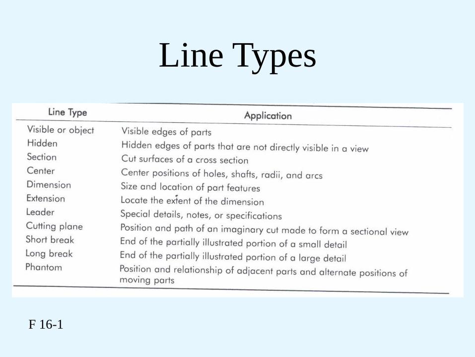
Line Types
F 16-1
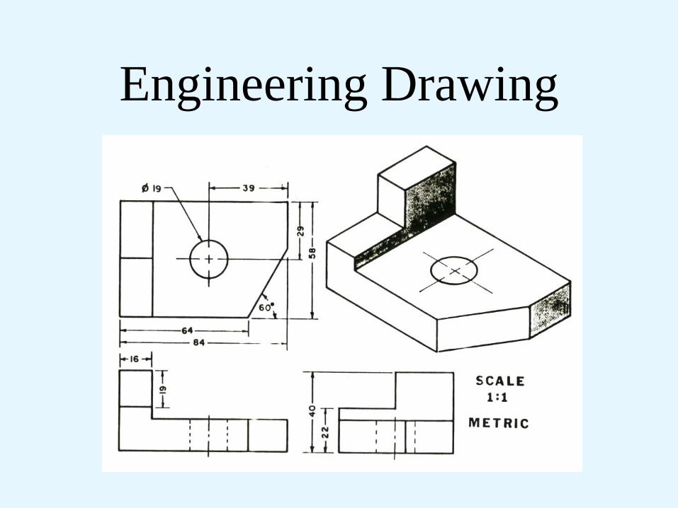
Engineering Drawing

Multiview Projection
F 16-2 Standards

Projection Symbols
F 16-3 Symbols
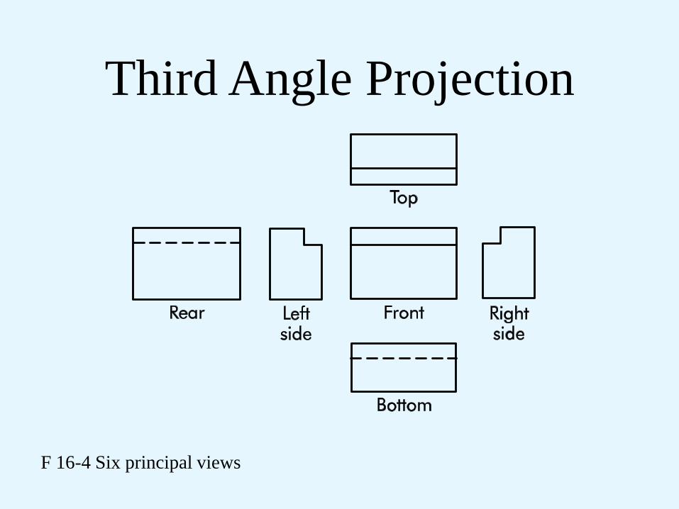
Third Angle Projection
F 16-4 Six principal views
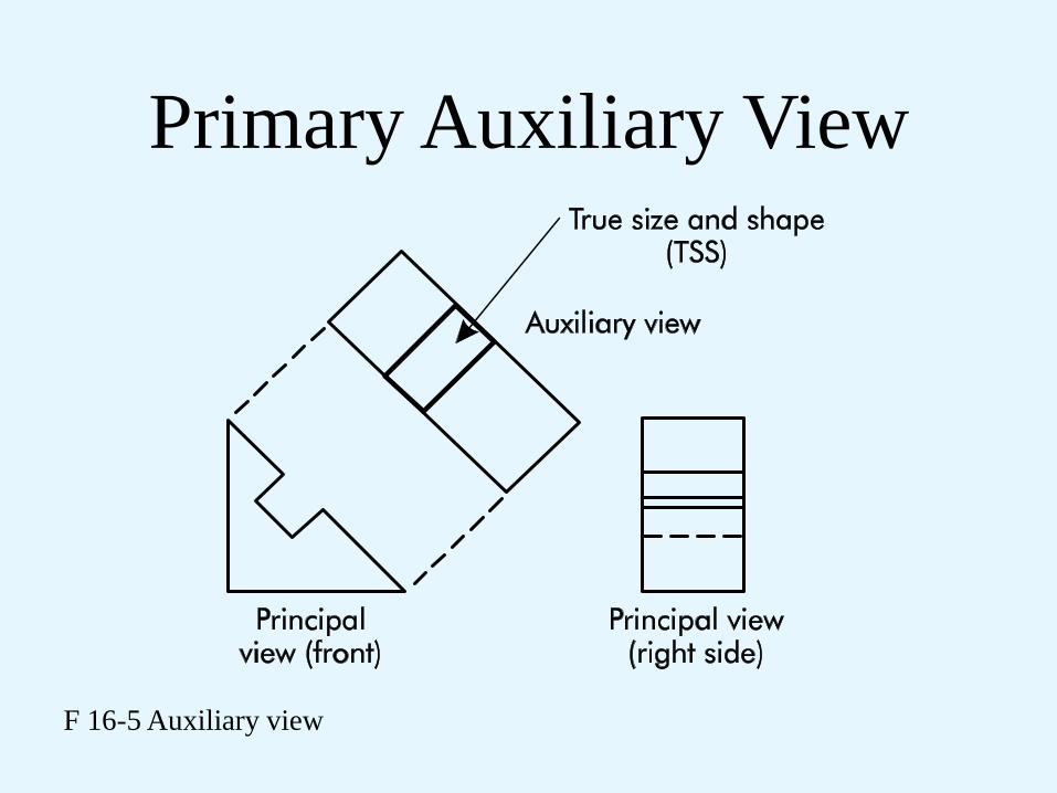
Primary Auxiliary View
F 16-5 Auxiliary view

Full Section
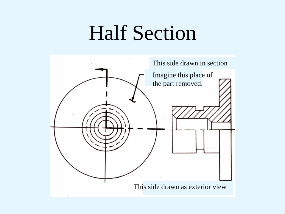
Half Section
This side drawn as exterior view
Imagine this place of
the part removed.
This side drawn in section
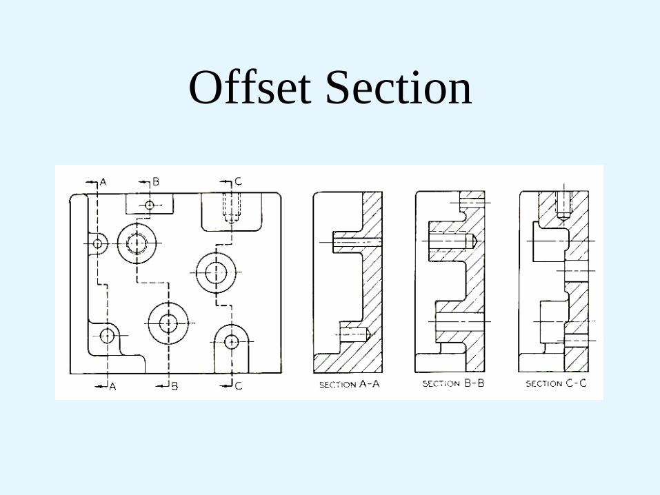
Offset Section

Offset Section
Do now show bends
in the cutting plane
Cutting plane

Dimensioning
F 16-8 Basic dimension

Dimensioning
F 16-9 Reference dimension

Dimensioning
F 16-10 Types of dimensioning
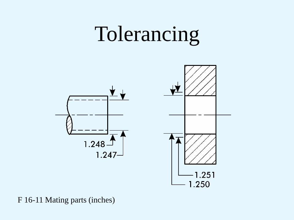
Tolerancing
F 16-11 Mating parts (inches)

Tolerancing
F 16-12 Mating parts (inches)

Tolerancing
F 16-13 Tolerances (inches)

System of Fits
• Hole basis: The system of fits where the
minimum hole size is the basic size.
• Shaft basis: The system of fits where the
minimum shaft size is the basic size

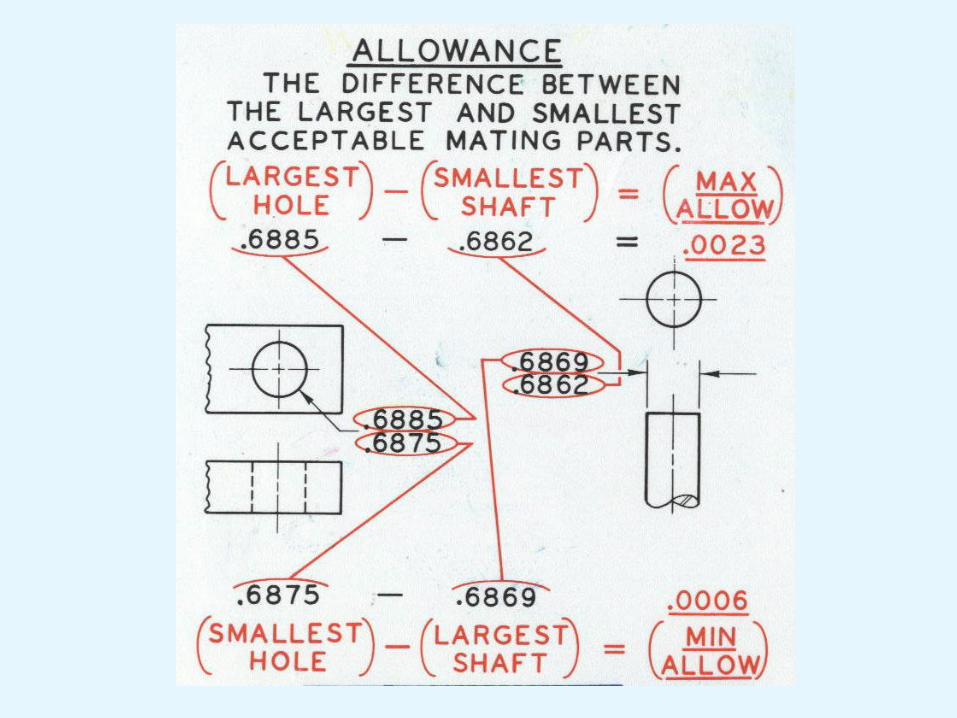
Fit Types
• Clearance: Gap between mating parts
• Interference: No clearance, force required
for assembly
• Transition: Result in either a clearance or an
interference fit

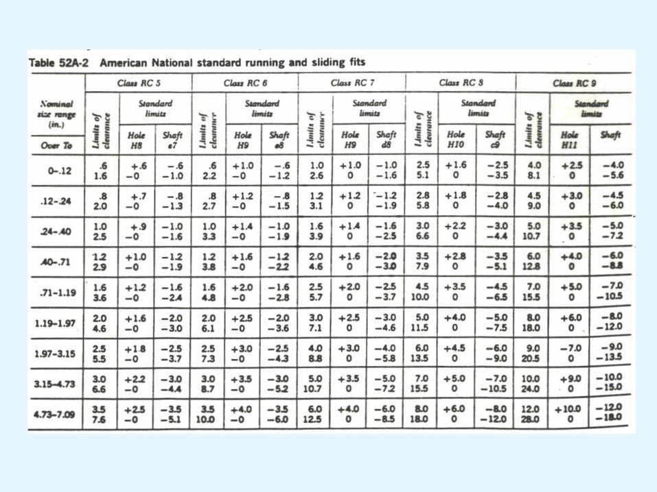
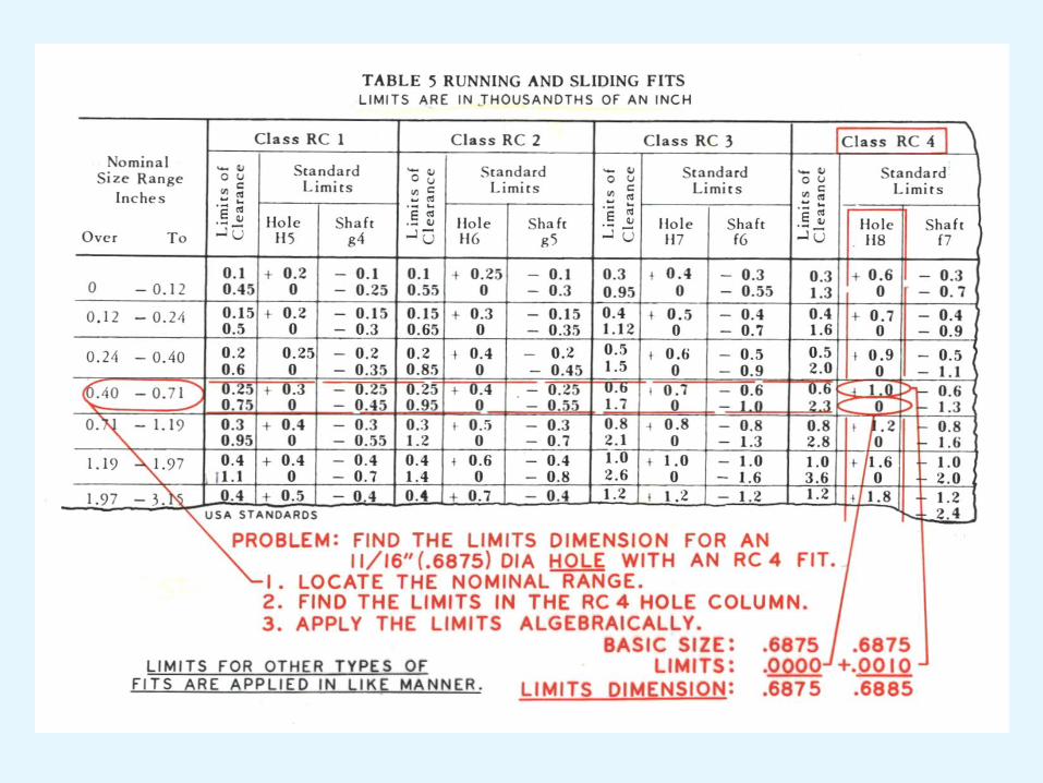
Types of Fits
• RC-running and sliding fits
• LC-clearance locational fits
• LT-transition locational fits
• LN-interference locational fits
• FN-force and shrink fits


Hole Basis
Shaft Basis Description
H11/c11
H9/d9
H8/f7
H7/g6
H7/h6
C11/hll
D9/h9
F8/h7
G7/h6
H7/h6
Loose running fit for wide commercial tolerances or
allowances on external members.
Free running fit for running accurate machines and
for accurate location at moderate speeds and journal
pressures.
Close running fit for running on accurate machines
and for accurate location at moderate speeds and
journal pressures.
Sliding fit not intended to run freely, but to move and
turn freely and locate accurately.
Locational clearance fit provides snug fit for locating
stationary parts: but can freely assembled and
disassembled.
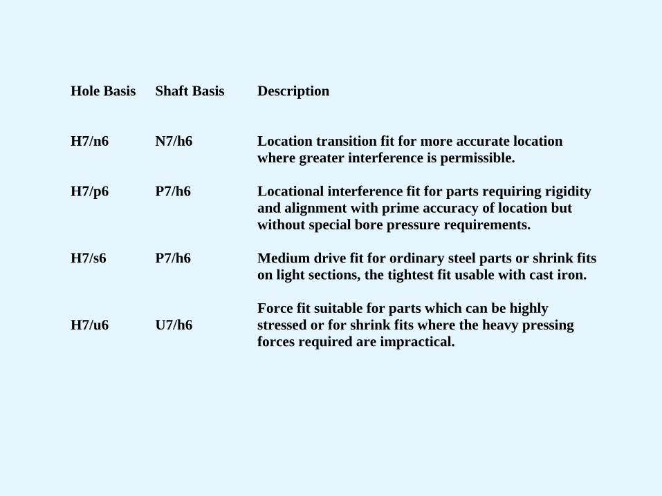
Hole Basis
Shaft Basis Description
H7/n6
H7/p6
H7/s6
H7/u6
N7/h6
P7/h6
P7/h6
U7/h6
Location transition fit for more accurate location
where greater interference is permissible.
Locational interference fit for parts requiring rigidity
and alignment with prime accuracy of location but
without special bore pressure requirements.
Medium drive fit for ordinary steel parts or shrink fits
on light sections, the tightest fit usable with cast iron.
Force fit suitable for parts which can be highly
stressed or for shrink fits where the heavy pressing
forces required are impractical.

Symbols and Their Definitions as Applied Holes and Shafts
• Basic Size
• HOLE
• Fundamental Deviation
• Basic Size
• SHAFT
• Fundamental Deviation
• Basic Size
• FIT
• Hole Tolerance
• Tolerance Grade
• IT Grade
• Tolerance Grade
• IT Grade
• Fit
• Shaft Tolerance
40 H8
40 H8/f7
40 F7

Tolerances for Interchangeability
F 16-14 Car knob assembly
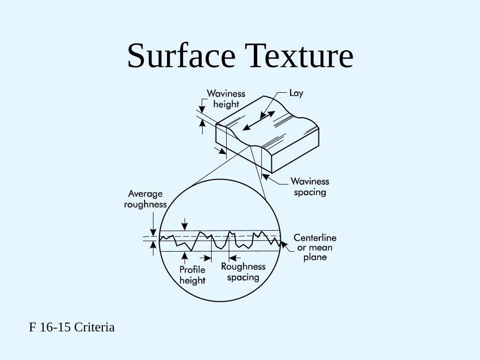
Surface Texture
F 16-15 Criteria
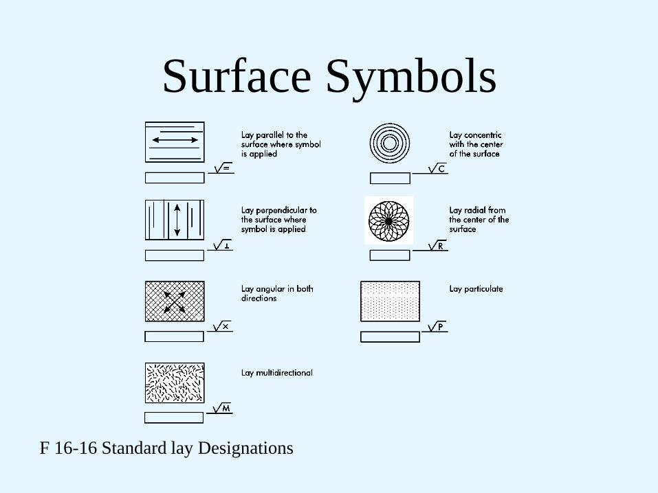
Surface Symbols
F 16-16 Standard lay Designations

Surface Symbols
F 16-17 Applications

Geometric Dimensioning
and Tolerancing
Chapter 17

F 17-1 ASME Y14.5M-1994

F 17-2 GD&T Tolerances and Symbols

F 17-3 Feature control frame

F 17-4 Flatness
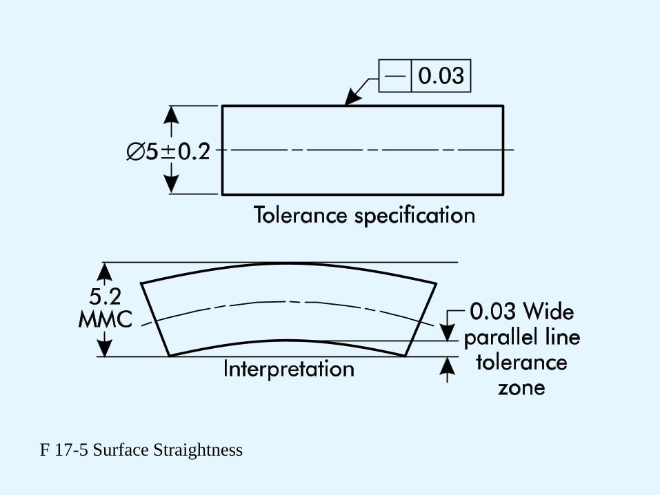
F 17-5 Surface Straightness
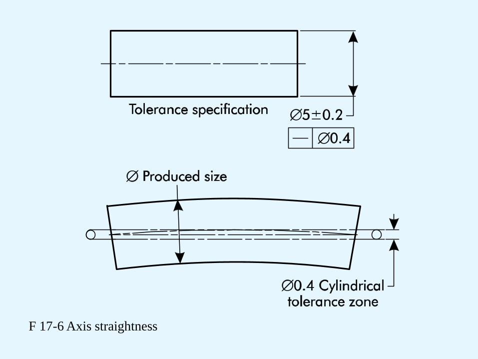
F 17-6 Axis straightness
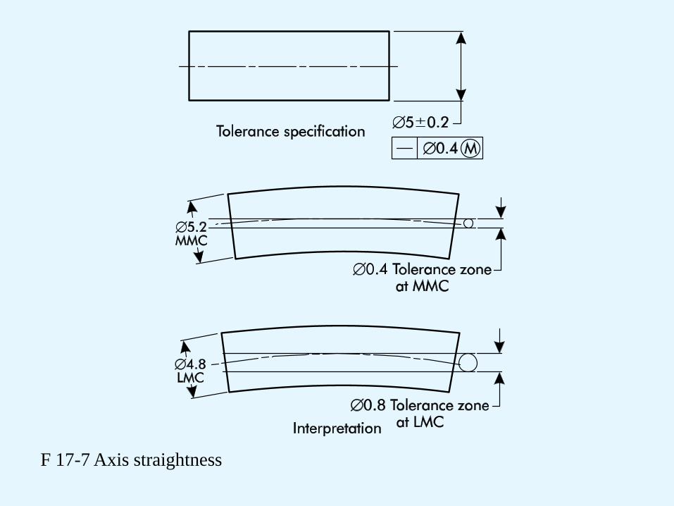
F 17-7 Axis straightness

F 17-8 Circularity
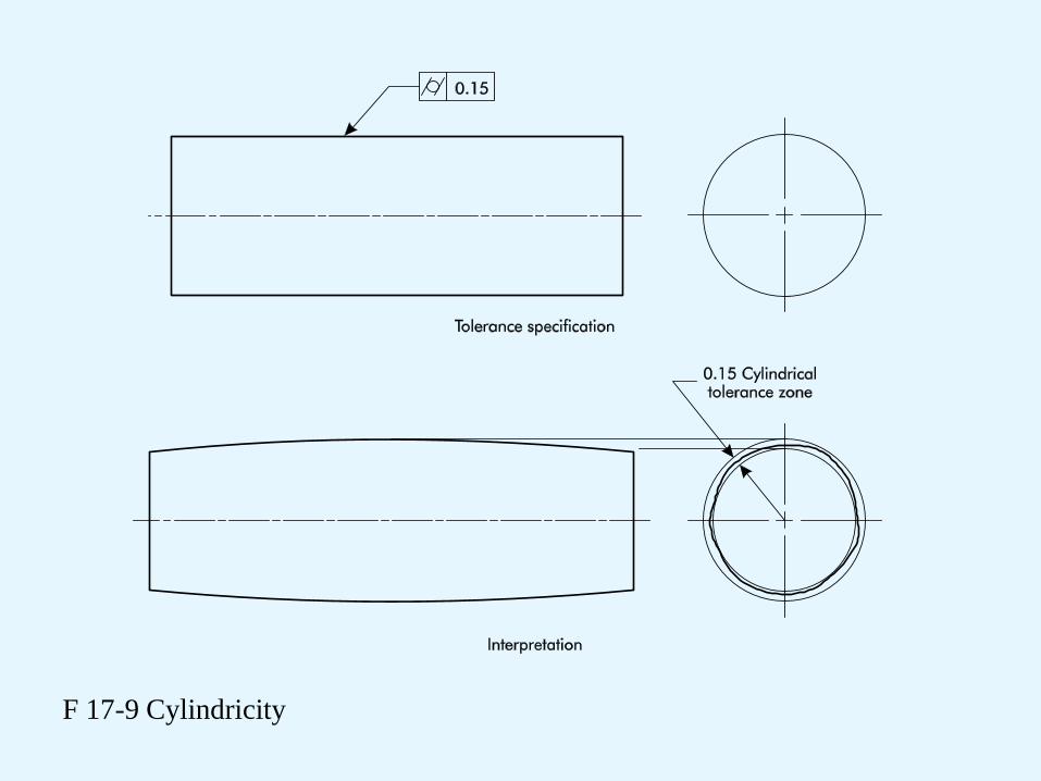
F 17-9 Cylindricity
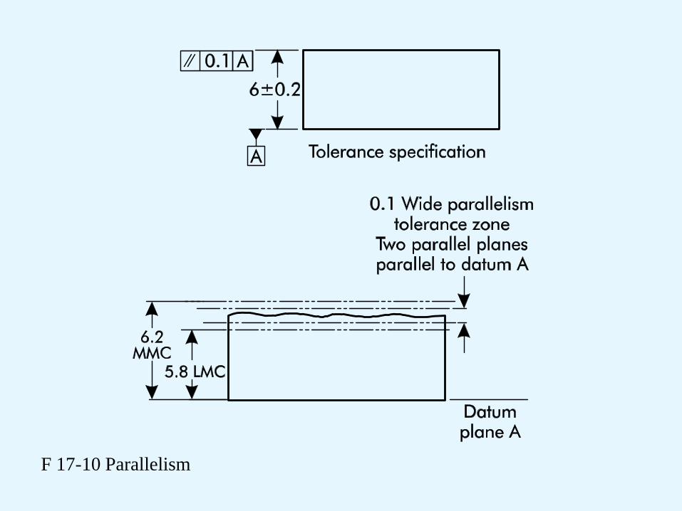
F 17-10 Parallelism

F 17-11 Perpendicularity

F 17-12 Angularity

F 17-13 Circular runout

F 17-14 Total runout
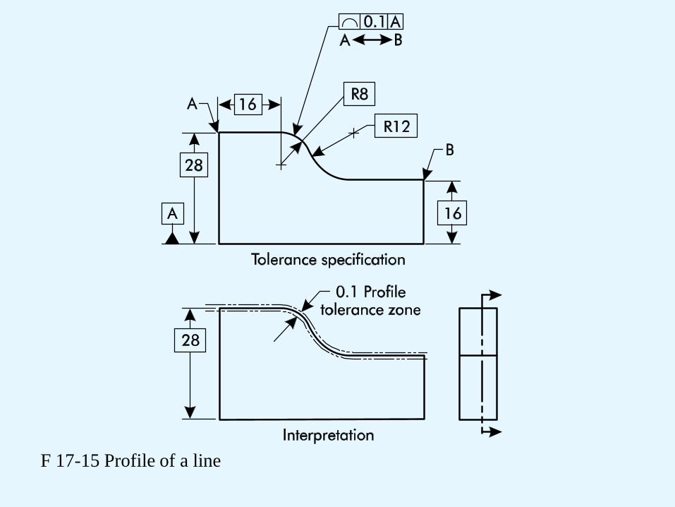
F 17-15 Profile of a line
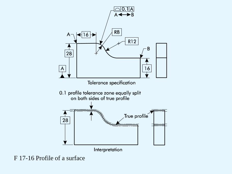
F 17-16 Profile of a surface
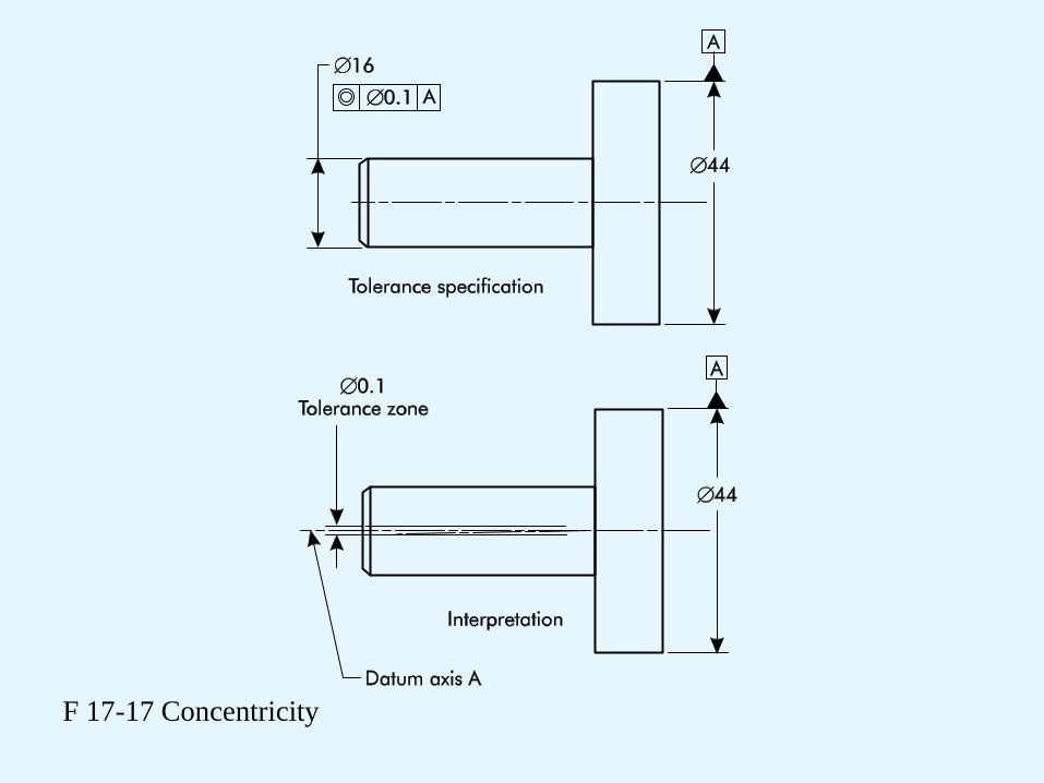
F 17-17 Concentricity
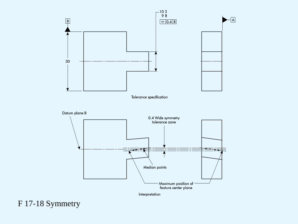
F 17-18 Symmetry
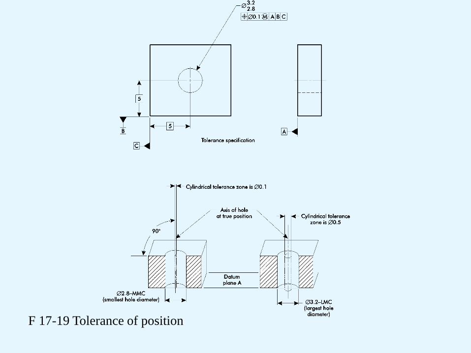
F 17-19 Tolerance of position
Computer-Aided Design
Chapter 18

3D Modeling Methods
• 1. Wire Frame
• 2. Surface Modeling
• 3. Solid Modeling
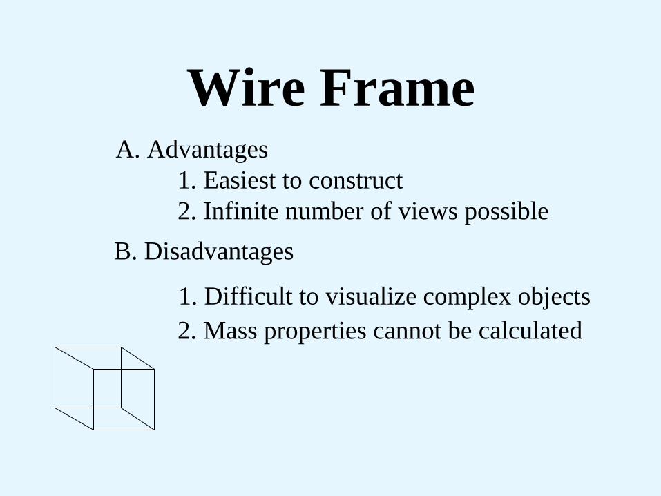
Wire Frame
A. Advantages
1. Easiest to construct
2. Infinite number of views possible B. Disadvantages
1. Difficult to visualize complex objects
2. Mass properties cannot be calculated
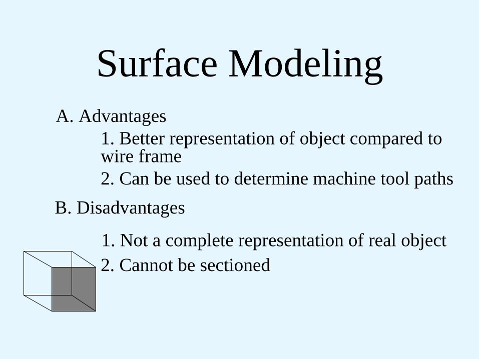
Surface Modeling
A. Advantages
1. Better representation of object compared to wire frame
2. Can be used to determine machine tool paths B. Disadvantages
1. Not a complete representation of real object
2. Cannot be sectioned

Solid Modeling
A. Advantages
1. True 3D object
2. Elimination of ambiguity in viewing model
3. Section cuts can be produced and displayed
4. Mass properties may be calculated B. Disadvantages
1. Software more expensive
2. More memory is required

Modeling Uses

Circuit Board Layout
• CAD software designed for printed circuit
boards (PCB) has features unique to that
application.
• Current surface mount technology (SMT)
and the continued miniaturization of
integrated-circuit products makes the
design of most PCBs a complex task
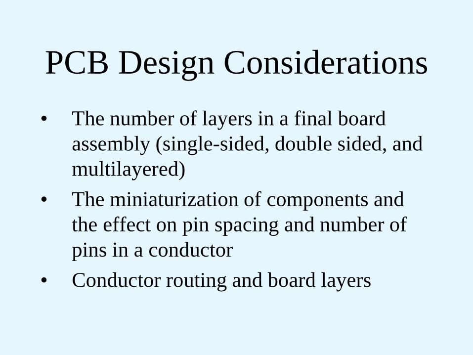
PCB Design Considerations
• The number of layers in a final board
assembly (single-sided, double sided, and
multilayered)
• The miniaturization of components and
the effect on pin spacing and number of
pins in a conductor
• Conductor routing and board layers
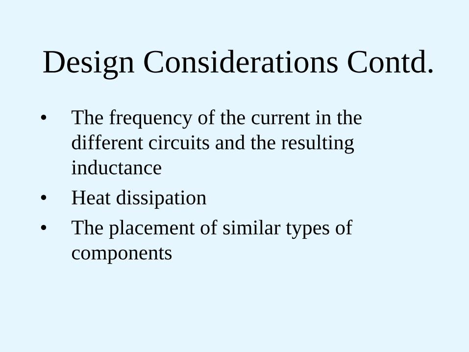
Design Considerations Contd.
• The frequency of the current in the
different circuits and the resulting
inductance
• Heat dissipation
• The placement of similar types of
components
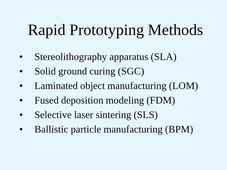
Rapid Prototyping Methods
• Stereolithography apparatus (SLA)
• Solid ground curing (SGC)
• Laminated object manufacturing (LOM)
• Fused deposition modeling (FDM)
• Selective laser sintering (SLS)
• Ballistic particle manufacturing (BPM)

Advantages of Rapid
Prototyping • Produce three dimensional parts within hours
• Create masters and patterns
• Accelerate prototype production
• Achieve major savings in production of soft and hard tooling
• Increase manufacturing capabilities with low volume production runs
• Add impact to marketing concept presentations with hands-on models
• Improve the accuracy of vendor bid response

Disadvantages of Rapid
Prototyping • Parts typically cannot be used for physical
testing
• Parts have surface finish quality and
tolerance limitations
• Special techniques and materials are
required of some systems
• Equipment is expensive

Product Design Tools
Chapter 19
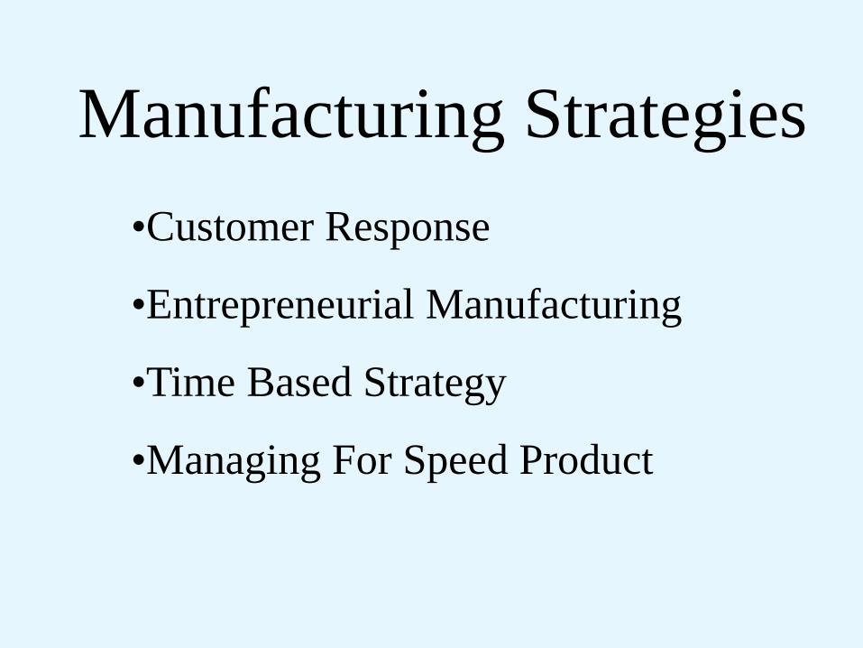
Manufacturing Strategies
•Customer Response
•Entrepreneurial Manufacturing
•Time Based Strategy
•Managing For Speed Product

Customer Responsive
•Targets quality improvement and customer
service
•Uses short-run manufacturing via the work
cell concept

Entrepreneurial Manufacturing
•Requires flexible system capable of shifting from one product to another on short notice
•Success is dependent upon a company’s capacity to create new markets for specialized high-value-added products.

Time Based Strategy
•Organization of process components and standardization
•Length of production run
•Complexity of scheduling procedures
•Favors smaller increments of improvement in new products, but introduces them more often

Managing for Speed Product
Depends on:
•Organizing product development for speed
•Organizing product manufacturing for speed
•Using miscellaneous techniques for speed
•Using computer-aided technology for speed

Manufacturing Strategies
All strategies focus on delivering a quality product at a
competitive price simultaneously responding to customer
needs, and striving for continuous improvement.
Entrepreneurial
Manufacturing
Customer
Responsive
Time Based Strategy
Managing For
Speed Product
Concurrent Engineering Principles
• Understand your customer
• Use product development teams
• Integrate process design
• Involve suppliers and subcontractors early
• Use digital product models
• Integrate CAE, CAD, and CAM tools
• Use quality engineering and reliability techniques
• Create an efficient development approach
• Improve the design process continuously
T 19-1
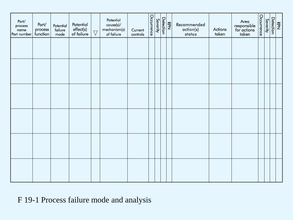
F 19-1 Process failure mode and analysis

Quality Function Deployment
(QFD)
• A strategy/technique of listening to the
“voice of the customer”

Benefits of Using a Quality Function
Deployment Strategy
• Earlier determination of key product characteristics
• Documentation of actual customers’ needs rather than
decisions based on opinions
• Reduction in product development costs
• Reduction in time required to bring a new product to
market
• Greater customer satisfaction due to lower costs and
improved responsiveness
• Reduction in number of engineering changes across the
product’s life cycle T 19-6

F 19-2 Four stages of QFD
Quality Function Deployment (QFD)

F 19-3 House of quality

F 19-4 QFD matrices
Group Technology (GT)
• An approach to reduce manufacturing
system information content by identifying
and exploiting the sameness or similarity of
parts based on their geometrical shape
and/or similarities in their production
process.
Part Families
• Design-oriented: Have similar design
feature, such as geometric shape
• Manufacturing-oriented: Can be based on
any number of different considerations,
such as parts manufactured by the same
plant or same materials
Methods of Grouping Parts
• Visual inspection
• Production flow analysis (PFA)
• Classification and coding
(Most effective and widely used)

Two Main Coding Systems
1. Attribute-based (polycodes)
2. Hierarchical-based (monocodes)

F 19-5 Attribute-based coding

F 19-6 Hierarchical-based coding


