
Product InformationProcess pressure transmitters
p
Level and Pressure

2 Process pressure transmitters
Contents
Contents
1 Product description ......................................................................................... 3
2 Function and application
2.1 Pressure measuring principles ........................................................................... 42.2 Principle of operation of the measuring cell ....................................................... 42.3 Features of the ceramic measuring cells ........................................................... 4
3 Types and versions
3.1 Instrument overview ............................................................................................. 63.2 Electronic versions ............................................................................................... 83.3 The differences at a glance ............................................................................... 103.4 Measuring ranges .............................................................................................. 113.5 Process fittings ................................................................................................... 143.6 Approvals and certificates ................................................................................ 15
4 Technical data
4.1 VEGABAR 14 ...................................................................................................... 164.2 VEGABAR 15 ...................................................................................................... 184.3 VEGABAR 40 ...................................................................................................... 204.4 VEGABAR 41 ...................................................................................................... 224.5 VEGABAR 44 ...................................................................................................... 244.6 VEGADIS 10 ....................................................................................................... 264.7 Ex technical data ................................................................................................ 274.8 Dimensions .......................................................................................................... 28
5 Mounting
5.1 Mounting instructions ......................................................................................... 365.2 Mounting VEGADIS 10 ....................................................................................... 36
6 Electrical connection
6.1 Connection instructions ...................................................................................... 376.2 Connection plans ................................................................................................ 386.3 Connection examples ........................................................................................ 396.4 Connection instructions for Ex-applications .................................................... 396.5 Connection examples for Ex-applications ....................................................... 40
7 Hot steam measurement with VEGABAR 40 ................................................. 41
8 Pressure transmitters with isolating diaphragms
8.1 General information on isolating diaphragms .................................................. 428.2 Applications ........................................................................................................ 428.3 Function ............................................................................................................... 428.4 Selection criteria ................................................................................................. 428.5 Error calculation .................................................................................................. 438.6 Application temperatures .................................................................................. 44
9 Accessories ................................................................................................... 46

Process pressure transmitters 3
Product description
Instrument features
• Dry ceramic measuring cells.• Ceramic measuring cell up to
150-fold overload resistant.• Resistant against abrasive and
corrosive products.• Continuous self-monitoring
right up to the diaphragm.• Measuring ranges for absolute
and relative pressure.• Digital output signal (Profibus
PA, HART®) or 4 … 20 mA out-put signal.
• Accuracy optionally 0.1 %,0.25 % or 0.5 %.
• Exact, digital processing ofmeasured data.
• Long-term stability better than0.1 %/12 months.
• Temperature stability betterthan 0.05 %/10 K.
• Turn down 1 : 30, Turn up+95 %.
• Medium temperatures up to400°C.
• Unpressurised adjustment (dryadjustment).
• Pointer function for pressureand temperature.
• Multisensor - two measuredvalues from one sensor:Profibus PA instruments deliverbeside the pressure signal alsothe measuring cell temperatureas additional information.
• Special aseptic applications forthe food processing and phar-maceutical industry (FDA, 3A,EHEDG certified).
• Adjustment/indication also inseparate housing VEGADIS 10possible.
1 Product description
These process pressure transmittersrepresent an efficient, proven sensorsystem for process pressure meas-urement. Ongoing development inconjunction with the latest advancesin materials science guarantee qual-ity and precision. Beside theirprocessing quality and high ageingresistance, the pressure transmittersare characterised by process fittingsexactly adapted to the measurementconditions. One common feature ofthe VEGA pressure transmitters is theincorporation of the completely dry,ceramic-capacitive CERTEC® meas-uring cell with a diaphragm of highpurity sapphire ceramic®.
Maximum accuracy and excellentlong-term stability characterise thesepressure transmitters. In cooperationwith various industries, pressuretransmitters for sophisticated appli-cations have been developed. Spe-cially adapted materials and designvariants enable their use in corrosiveand abrasive products as well as inprocesses with increased aseptic re-quirements (food processing or phar-maceutical industry).
The sensors are used in all industries:- Chemicals- Pharmaceutical/Cosmetics- Petrochemicals- Water/Waste water- Foodstuffs- Beverage industry- Paper industry- Shipbuilding- Printing industry- Mining- Mechanical engineering
Several versions for the output of themeasuring signal are available:- 4 … 20 mA- HART®
- Profibus PA
Process pressure transmitters arealso available in different adjustmentand indication versions.
Certified instruments are available foruse in hazardous areas, in pressu-rized vessels, in hygienic products oras part of an overfill protection sys-tem. They are certified acc. to:- CENELEC EEx ia IIC- PTB Ex-Zone 0 (Germany)- EHEDG- WHG- 3A- FDA
4 Process pressure transmitters
Function and application
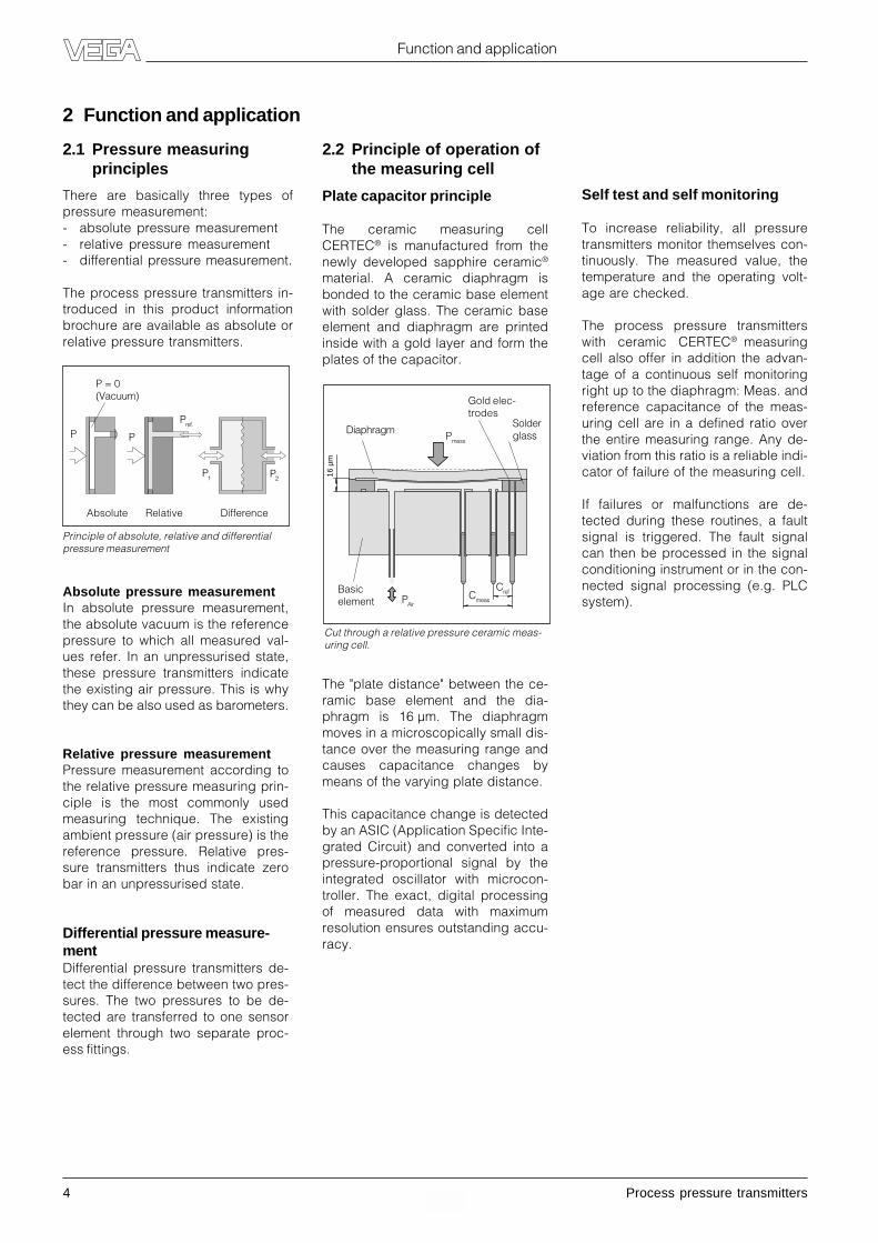
16 µ
m
Cut through a relative pressure ceramic meas-uring cell.
Gold elec-trodes
Pmess
Solderglass
2.1 Pressure measuringprinciples
There are basically three types ofpressure measurement:- absolute pressure measurement- relative pressure measurement- differential pressure measurement.
The process pressure transmitters in-troduced in this product informationbrochure are available as absolute orrelative pressure transmitters.
2 Function and application
Absolute pressure measurementIn absolute pressure measurement,the absolute vacuum is the referencepressure to which all measured val-ues refer. In an unpressurised state,these pressure transmitters indicatethe existing air pressure. This is whythey can be also used as barometers.
Relative pressure measurementPressure measurement according tothe relative pressure measuring prin-ciple is the most commonly usedmeasuring technique. The existingambient pressure (air pressure) is thereference pressure. Relative pres-sure transmitters thus indicate zerobar in an unpressurised state.
Differential pressure measure-mentDifferential pressure transmitters de-tect the difference between two pres-sures. The two pressures to be de-tected are transferred to one sensorelement through two separate proc-ess fittings.
2.2 Principle of operation ofthe measuring cell
Plate capacitor principle
The ceramic measuring cellCERTEC® is manufactured from thenewly developed sapphire ceramic®
material. A ceramic diaphragm isbonded to the ceramic base elementwith solder glass. The ceramic baseelement and diaphragm are printedinside with a gold layer and form theplates of the capacitor.
Principle of absolute, relative and differentialpressure measurement
Absolute Relative Difference
P1 P2
P P
Pref.
P = 0(Vacuum)
The "plate distance" between the ce-ramic base element and the dia-phragm is 16 µm. The diaphragmmoves in a microscopically small dis-tance over the measuring range andcauses capacitance changes bymeans of the varying plate distance.
This capacitance change is detectedby an ASIC (Application Specific Inte-grated Circuit) and converted into apressure-proportional signal by theintegrated oscillator with microcon-troller. The exact, digital processingof measured data with maximumresolution ensures outstanding accu-racy.
PAirCmeas
Cref
Diaphragm
Basicelement
Self test and self monitoring
To increase reliability, all pressuretransmitters monitor themselves con-tinuously. The measured value, thetemperature and the operating volt-age are checked.
The process pressure transmitterswith ceramic CERTEC® measuringcell also offer in addition the advan-tage of a continuous self monitoringright up to the diaphragm: Meas. andreference capacitance of the meas-uring cell are in a defined ratio overthe entire measuring range. Any de-viation from this ratio is a reliable indi-cator of failure of the measuring cell.
If failures or malfunctions are de-tected during these routines, a faultsignal is triggered. The fault signalcan then be processed in the signalconditioning instrument or in the con-nected signal processing (e.g. PLCsystem).

Process pressure transmitters 5
Overload resistantThe CERTEC® sapphire ceramic®
measuring cell exhibits overload re-sistance up to 150 fold. A flowing liq-uid suddenly blocked by a valve clos-ing in 20 ms, produces local shockwaves with 20 to 40 times the nominalpressure. For a few milliseconds, thepressure rises to levels that can de-stroy sensors with a lower overloadresistance.
Features of the CERTEC® measur-ing cell• Dry, ceramic-capacitive sensor el-
ement of sapphire ceramic® (99.9 %Al2O3).
• Versions for relative and absolutepressure (measuring ranges from -1 bar … 0.1 bar … 60 bar).
• Up to 150 fold overload resistance(also dynamic!).
• Excellent long-term stability andreproducibility.
• Excellent abrasion and corrosionresistance.
• Minimal internal air volume.• Absolutely flush mounting possible.• FDA tested.• Integrated continuous self-monito-
ring.• Integrated temperature sensor.
metallic processfitting
Form seal
Ceramic
Absolutely flush ceramic pressure transmitterswith patented seal concept
Function and application
2.3 Features of the ceramicmeasuring cells
The sapphire ceramic® developed byVEGA consists of a special fine-grained aluminium oxide with an av-erage grain size of only 2.5 µm, incontrast to other ceramics that have agrain size of more than 30 µm. With apreviously unreached purity of99.9 %, the CERTEC® sapphire ce-ramic® exhibits undreamt-of me-chanical and chemical properties:- completely hysteresis-free- ideal elastic properties- extremely overload resistant- maximum corrosion and acid re-
sistance- resistant to very abrasive products- maximum hardness- absolutely ageing-resistant
Chemically resistantIn field tests and test series using10 % caustic soda solution, hydro-chloric acid, sulphuric acid, phos-phoric acid and nitric acid for artificialageing, sapphire ceramic® hasproven to be a highly corrosion resist-ant material.
Abrasion resistantAbrasion is basically a machiningprocess in which very small hard par-ticles remove microscopically smallchips. Ceramic is resistant to thisabrasion process.
Ten times harder than stainless steel,the sapphire ceramic® diaphragm ef-fectively prevents wear, abrasion ordamage of the diaphragm by micro-scopic chipping. Whether caused bypaper pulp carrying metal particles,which can act like grinding paste, orby nut chocolate which, due to nutfragments, can be extremely erosive,the hard ceramic material can with-stand any form of diaphragm abra-sion.
Absolutely flushThe seal concept unique in compari-son to other sensors, enables perfectflushness, a critical factor in manyapplications.
In the food processing and pharma-ceutical industry, flushness is the keyto solving the well-known problemsregarding the instrumentation of aplant. Beside the expected high dura-bility, accuracy, long-term stability,ruggedness and user-friendly setup,a sensor must also meet utmost hygi-enic and aseptic requirements. GMP,GHP, FDA, sterilisation, EHEDG and3A are the requirements measure-ment technology always has to meetin the food processing and pharma-ceutical industry. The sensor must bereliably cleaned or sterilised with CIP(Cleaning in place) and SIP (Sterilisa-tion in place). Perfect flushness is thesolution.
Dirt and impurities mainly stick inpores, gaps, shoulders andscratches. Such are avoided by theflushness and surface quality.

6 Process pressure transmitters
Types and versions
3 Types and versions
3.1 Instrument overview
VEGABAR 14
Process pressure transmitterswith CERTEC®
- dry, ceramic-capacitive sensor el-ement
- up to 150-fold overload resistance- two-wire system 4 … 20 mA- supply voltage 12 … 30 V- zero point shift ± 5 % without cur-
rent limitation (with IP 65)- housing with connecting plug acc.
to DIN 43 650 in protection IP 65- housing with direct cable outlet in
protection IP 67- accuracy class 0.5
Applications:Pressure measurement of gases, va-pours and liquids in all areas of proc-ess control technology.
- two-wire system 4 … 20 mA- supply voltage 10 … 30 V- housing with connection plug acc.
to DIN 43 650 in protection IP 65- process fitt ing G1/2A acc. to
DIN 16 288 of 1.4404- accuracy class 0.3
Applications:Pressure measurement of gases, va-pours and liquids in all areas of proc-ess control technology.
With flush diaphragm for dense liq-uids, non-uniform and crystallisingproducts.
VEGABAR 15
Process pressure transmitterswith piezoresistive sensor element
VEGADIS 10
External indicating instrument
- external housing for surface mount-ing with adjustment/display forVEGABAR 40 … 44 process pres-sure transmitters
- LC display for digital and quasi-analogue display of measured val-ues
- display range -9999 … 9999, withindividually adjustable decimalpoint
- protection IP 66/IP 67

Process pressure transmitters 7
VEGABAR 41
Process pressure transmitterswith isolating diaphragm
Types and versions
VEGABAR 40
Process pressure transmitterswith internal CERTEC®
- dry, ceramic-capacitive sensor el-ement
- up to 150-fold overload resistance- repair and service-friendly through
interchangeable process fittingswith measuring cell and inter-changeable electronics requiringno fresh adjustment
- microcomputer controlled electron-ics with Profibus-PA interface or two-wire system 4 … 20 mA, HART®,VVO
- optional: continuous self-monitor-ing of electronics and measuringcell
- housing of powder-coated alu-minium or durable, shock-resistantplastic in protection IP 65
- adjustment/indication also in sepa-rate housing VEGADIS 10 possible
- TÜV tested acc. to regulations forpressurized vessels
Applications:Pressure measurement of gases, va-pours, liquids and dusts in all areas ofprocess technology.
- interchangeable electronics requir-ing no fresh adjustment
- microcomputer controlled electron-ics with Profibus-PA interface or two-wire system 4 … 20 mA, HART®, VVO
- housing of powder-coated alu-minium or durable, shock-resistantplastic in protection IP 65
- adjustment/indication also in sepa-rate housing VEGADIS 10 possible
Applications:Pressure detection in very corrosiveproducts at high process tempera-tures.
VEGABAR 44
Process pressure transmitterswith flush CERTEC®
- dry, ceramic-capacitive sensor el-ement
- up to 150-fold overload resistance- interchangeable electronics requir-
ing no fresh adjustment- microcomputer controlled electron-
ics with Profibus-PA interface or two-wire system 4 … 20 mA, HART®,VVO
- optional: continuous self-monitor-ing of electronics and measuringcell
- housing of powder-coated alu-minium or durable, shock-resistantplastic in protection IP 65
- adjustment/indication also in sepa-rate housing VEGADIS 10 possible
Applications:Pressure detection of abrasive, highviscosity products such as in the pa-per, chemical, food processing, phar-maceutical and water/waste water in-dustries.
8 Process pressure transmitters
Types and versions
3.2 Electronics versions
Connection technologies
There are basically three differentconnection technologies for VEGAprocess pressure transmitters.
4 … 20 mADependent on the pressure, the proc-ess pressure transmitter consumes acurrent between 4 mA and 20 mA.This current is a measure on the pres-sure or the level (e.g. 4 mA corre-spond to 0 bar, 20 mA correspond to10 bar).
HART®
Pressure transmitters with HART®
technology also consume a supplycurrent between 4 mA and 20 mA,which corresponds to the acting pres-sure. In addition a digital signal con-taining information from the pressuretransmitter, e.g. on the acting pres-sure, is superimposed on the current.At the same time, these signals arealso used to transmit commands, e.g.for adjustment.
The operating mode "Multidrop" isalso possible. Several instrumentsare connected in parallel to one two-wire cable (max. 15). Each instrumentmust have an address for identifica-tion. The current consumption ofeach instrument is 4 mA.
Profibus PAProfibus PA is an open field bus espe-cially for process technology. Withthis it is possible to connect severalsensors, also in Ex area, to one buscable. The connection is carried outin two-wire technology, but with spe-cial cable types.
A diskette with the sensor master file,to enable connection to the Profibussystem, comes with the pressuretransmitter. This file contains informa-tion required for programming, e.g. ofa PLC. These files are also availableon the VEGA homepage as downloadfiles (www.vega.com).
Adjustment versions
The VEGA process pressure transmit-ters can be adjusted (configurationand parameter adjustment) in differ-ent ways depending on the instru-ment version.
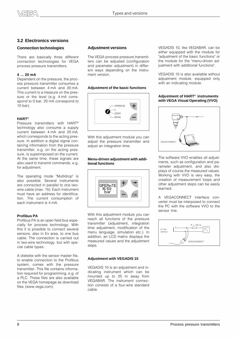
Adjustment of the basic functions
VEGADIS 10, like VEGABAR, can beeither equipped with the module for"adjustment of the basic functions" orthe module for the "menu-driven ad-justment with additional functions".
VEGADIS 10 is also available withoutadjustment module, equipped onlywith an indicating module.
Adjustment of HART® instrumentswith VEGA Visual Operating (VVO)
OPERATE
t iZERO
SPAN
With this adjustment module you canadjust the pressure transmitter andadjust an integration time.
Menu-driven adjustment with addi-tional functions
OK
The software VVO enables all adjust-ments, such as configuration and pa-rameter adjustment, and also dis-plays of course the measured values.Working with VVO is very easy, thecreation of measurement loops andother adjustment steps can be easilylearned.
A VEGACONNECT interface con-verter must be interposed to connectthe PC with the software VVO to thesensor line.
+
{ –
VEGACONNECT
to thesensor
R = 100 �
VEGACONNECT
With this adjustment module you canreach all functions of the pressuretransmitter (adjustment, integrationtime adjustment, modification of themenu language, simulation etc.). Inaddition, an LCD matrix displays themeasured values and the adjustmentsteps.
Adjustment with VEGADIS 10
VEGADIS 10 is an adjustment and in-dicating instrument which can bemounted up to 25 m away fromVEGABAR. The instrument connec-tion consists of a four-wire standardcable.
Process pressure transmitters 9
Types and versions
Adjustment with HART® handheld
Here also, all functions of the pres-sure transmitter can be adjusted. Themeasured values and other informa-tion of the pressure transmitter aredisplayed on the HART® display.
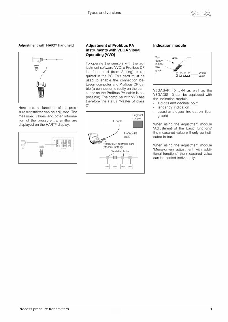
Indication module
VEGABAR 40 … 44 as well as theVEGADIS 10 can be equipped withthe indication module.- 4 digits and decimal point- tendency indication- quasi-analogue indication (bar
graph)
When using the adjustment module"Adjustment of the basic functions"the measured value will only be indi-cated in bar.
When using the adjustment module"Menu-driven adjustment with addi-tional functions" the measured valuecan be scaled individually.
250 W
Ri < 250 W
+
–
Ten-dencyindica-tionBargraph
Digitalvalue
Sensor Sensor Sensor Sensor
VVO
Segmentcoupler
Profibus PAcable
Profibus DP interface card(Messrs. Softing)
DP cable
Field distributor
Adjustment of Profibus PAinstruments with VEGA VisualOperating (VVO)
To operate the sensors with the ad-justment software VVO, a Profibus DPinterface card (from Softing) is re-quired in the PC. This card must beused to enable the connection be-tween computer and Profibus DP ca-ble (a connection directly on the sen-sor or on the Profibus PA cable is notpossible). The computer with VVO hastherefore the status "Master of class2".

10 Process pressure transmitters
Types and versions
3.3 The differences at a glance
The table clearly shows the main criteria and the differences between the process pressure transmitters.
VEGABAR 14 15 40 41 44
Electrical interface- 4 … 20 mA • •- 4 … 20 mA and HART® • • •- Profibus PA • • •
Adjustment options- basic function module • • •- menu-guided adjustment • • •- VEGA Visual Operating • • •- HART® handheld • • •- adjustment with VEGADIS 10 • • •
Indication- internal indication • • •- indication with VEGADIS 10 • • •
Plastic housing • • •
Metal housing • • • • •
Version in EExd • • •
Tested acc. to DruckbehV • • •
Flush process fittings • • •
Process fittings of PVDF •
High process temperature/Special materials •
Gauge pressure range in bar- smallest measuring range 0…0.1 0…1 0…0.1 0…0.4 0…0.1- largest measuring range 0…60 0…600 -1…60 -1…60 -1…60
Absolute pressure range in bar- smallest measuring range 0…1 –– 0…1 0…1 0…1- largest measuring range 0…60 –– 0…60 0…60 0…60
Accuracy class 0.5 0.3 0.1 0.1 0.10.25 0.25 0.25
Interchangeable process fitting •
Interchangeable electronics(without new adjustment) • • •
Process pressure transmitters 11
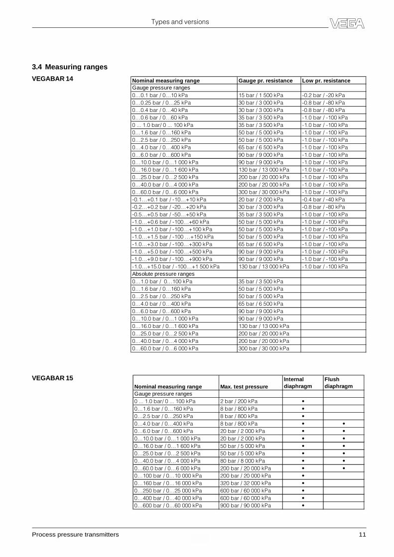
3.4 Measuring ranges
Types and versions
VEGABAR 14 Nominal measuring range Gauge pr. resistance Low pr. resistanceGauge pressure ranges0…0.1 bar / 0…10 kPa 15 bar / 1 500 kPa -0.2 bar / -20 kPa0…0.25 bar / 0…25 kPa 30 bar / 3 000 kPa -0.8 bar / -80 kPa0…0.4 bar / 0…40 kPa 30 bar / 3 000 kPa -0.8 bar / -80 kPa0…0.6 bar / 0…60 kPa 35 bar / 3 500 kPa -1.0 bar / -100 kPa0 ... 1.0 bar/ 0 ... 100 kPa 35 bar / 3 500 kPa -1.0 bar / -100 kPa0…1.6 bar / 0…160 kPa 50 bar / 5 000 kPa -1.0 bar / -100 kPa0…2.5 bar / 0…250 kPa 50 bar / 5 000 kPa -1.0 bar / -100 kPa0…4.0 bar / 0…400 kPa 65 bar / 6 500 kPa -1.0 bar / -100 kPa0…6.0 bar / 0…600 kPa 90 bar / 9 000 kPa -1.0 bar / -100 kPa0…10.0 bar / 0…1 000 kPa 90 bar / 9 000 kPa -1.0 bar / -100 kPa0…16.0 bar / 0…1 600 kPa 130 bar / 13 000 kPa -1.0 bar / -100 kPa0…25.0 bar / 0…2 500 kPa 200 bar / 20 000 kPa -1.0 bar / -100 kPa0…40.0 bar / 0…4 000 kPa 200 bar / 20 000 kPa -1.0 bar / -100 kPa0…60.0 bar / 0…6 000 kPa 300 bar / 30 000 kPa -1.0 bar / -100 kPa-0.1…+0.1 bar / -10…+10 kPa 20 bar / 2 000 kPa -0.4 bar / -40 kPa-0.2…+0.2 bar / -20…+20 kPa 30 bar / 3 000 kPa -0.8 bar / -80 kPa-0.5…+0.5 bar / -50…+50 kPa 35 bar / 3 500 kPa -1.0 bar / -100 kPa-1.0…+0.6 bar / -100…+60 kPa 50 bar / 5 000 kPa -1.0 bar / -100 kPa-1.0…+1.0 bar / -100…+100 kPa 50 bar / 5 000 kPa -1.0 bar / -100 kPa-1.0…+1.5 bar / -100 …+150 kPa 50 bar / 5 000 kPa -1.0 bar / -100 kPa-1.0…+3.0 bar / -100…+300 kPa 65 bar / 6 500 kPa -1.0 bar / -100 kPa-1.0…+5.0 bar / -100…+500 kPa 90 bar / 9 000 kPa -1.0 bar / -100 kPa-1.0…+9.0 bar / -100…+900 kPa 90 bar / 9 000 kPa -1.0 bar / -100 kPa-1.0…+15.0 bar / -100…+1 500 kPa 130 bar / 13 000 kPa -1.0 bar / -100 kPaAbsolute pressure ranges0…1.0 bar / 0…100 kPa 35 bar / 3 500 kPa0…1.6 bar / 0…160 kPa 50 bar / 5 000 kPa0…2.5 bar / 0…250 kPa 50 bar / 5 000 kPa0…4.0 bar / 0…400 kPa 65 bar / 6 500 kPa0…6.0 bar / 0…600 kPa 90 bar / 9 000 kPa0…10.0 bar / 0…1 000 kPa 90 bar / 9 000 kPa0…16.0 bar / 0…1 600 kPa 130 bar / 13 000 kPa0…25.0 bar / 0…2 500 kPa 200 bar / 20 000 kPa0…40.0 bar / 0…4 000 kPa 200 bar / 20 000 kPa0…60.0 bar / 0…6 000 kPa 300 bar / 30 000 kPa
VEGABAR 15Nominal measuring range Max. test pressure
Internal diaphragm
Flush diaphragm
Gauge pressure ranges0 ... 1.0 bar/ 0 ... 100 kPa 2 bar / 200 kPa •0…1.6 bar / 0…160 kPa 8 bar / 800 kPa •0…2.5 bar / 0…250 kPa 8 bar / 800 kPa •0…4.0 bar / 0…400 kPa 8 bar / 800 kPa • •0…6.0 bar / 0…600 kPa 20 bar / 2 000 kPa • •0…10.0 bar / 0…1 000 kPa 20 bar / 2 000 kPa • •0…16.0 bar / 0…1 600 kPa 50 bar / 5 000 kPa • •0…25.0 bar / 0…2 500 kPa 50 bar / 5 000 kPa • •0…40.0 bar / 0…4 000 kPa 80 bar / 8 000 kPa • •0…60.0 bar / 0…6 000 kPa 200 bar / 20 000 kPa • •0…100 bar / 0…10 000 kPa 200 bar / 20 000 kPa •0…160 bar / 0…16 000 kPa 320 bar / 32 000 kPa •0…250 bar / 0…25 000 kPa 600 bar / 60 000 kPa •0…400 bar / 0…40 000 kPa 600 bar / 60 000 kPa •0…600 bar / 0…60 000 kPa 900 bar / 90 000 kPa •

12 Process pressure transmitters
Types and versions
VEGABAR 40 and 44 Nominal measuring range Gauge pr. resistance Low pr. resistanceGauge pressure0…0.1 bar / 0…10 kPa 15 bar / 1 500 kPa -0.2 bar / -20 kPa0…0.2 bar / 0…20 kPa 20 bar / 2 000 kPa -0.4 bar / -40 kPa0…0.4 bar / 0…40 kPa 30 bar / 3 000 kPa -0.8 bar / -80 kPa0…1.0 bar / 0…100 kPa 35 bar / 3 500 kPa -1.0 bar / -100 kPa0…2.5 bar / 0…250 kPa 50 bar / 5 000 kPa -1.0 bar / -100 kPa0…5.0 bar / 0…500 kPa 65 bar / 6 500 kPa -1.0 bar / -100 kPa0…10.0 bar / 0…1 000 kPa 90 bar / 9 000 kPa -1.0 bar / -100 kPa0…20.0 bar / 0…2 000 kPa 130 bar / 13 000 kPa -1.0 bar / -100 kPa0…40.0 bar / 0…4 000 kPa 200 bar / 20 000 kPa -1.0 bar / -100 kPa0…60.0 bar / 0…6 000 kPa 300 bar / 30 000 kPa -1.0 bar / -100 kPa-0.05…+0.05 bar / -5…+5 kPa 15 bar / 1 500 kPa -0.2 bar / -20 kPa-0.1…+0.1 bar / -10…+10 kPa 20 bar / 2 000 kPa -0.4 bar / -40 kPa-0.2…+0.2 bar / -20…+20 kPa 30 bar / 3 000 kPa -0.8 bar / -80 kPa-0.5…+0.5 bar / -50…+50 kPa 35 bar / 3 500 kPa -1.0 bar / -100 kPa-1.0…0.0 bar / -100…0 kPa 35 bar / 3 500 kPa -1.0 bar / -100 kPa-1.0…+1.5 bar / -100…+150 kPa 50 bar /5 000 kPa -1.0 bar / -100 kPa-1.0…+4.0 bar / -100…+400 kPa 65 bar / 6 500 kPa -1.0 bar / -100 kPa-1.0…+10.0 bar / -100…+1 000 kPa 90 bar / 9 000 kPa -1.0 bar / -100 kPa-1.0…+20.0 bar / -100…+2 000 kPa 130 bar / 13 000 kPa -1.0 bar / -100 kPa-1.0 …+40.0 bar / -100…+4 000 kPa 200 bar / 20 000 kPa -1.0 bar / -100 kPa-1.0…+60.0 bar / -100…+6 000 kPa 300 bar / 30 000 kPa -1.0 bar / -100 kPaAbsolute pressure0…1.0 bar / 0…100 kPa 35 bar / 3 500 kPa0…2.5 bar / 0…250 kPa 50 bar / 5 000 kPa0…5.0 bar / 0 …500 kPa 65 bar / 6 500 kPa0…10.0 bar / 0…1 000 kPa 90 bar / 9 000 kPa0…20.0 bar / 0…2 000 kPa 130 bar / 13 000 kPa0…40.0 bar / 0…4 000 kPa 200 bar / 20 000 kPa0…60.0 bar / 0…6 000 kPa 300 bar / 30 000 kPa

Process pressure transmitters 13
Types and versions
VEGABAR 41 Nominal pressure range Gauge pr. resistance Low pr. resistanceGauge pressure0…0.4 bar / 0…40 kPa 30 bar / 3 000 kPa -0.8 bar / -80 kPa0…1.0 bar / 0…100 kPa 35 bar / 3 500 kPa -1.0 bar / -100 kPa0…2.5 bar / 0…250 kPa 50 bar / 5 000 kPa -1.0 bar / -100 kPa0…5.0 bar / 0…500 kPa 65 bar / 6 500 kPa -1.0 bar / -100 kPa0…10.0 bar / 0…1 000 kPa 90 bar / 9 000 kPa -1.0 bar / -100 kPa0…20.0 bar / 0…2 000 kPa 130 bar / 13 000 kPa -1.0 bar / -100 kPa0…40.0 bar / 0…4 000 kPa 200 bar / 20 000 kPa -1.0 bar / -100 kPa0…60.0 bar / 0…6 000 kPa 300 bar / 30 000 kPa -1.0 bar / -100 kPa-0.05…+0.05 bar / -5…+5 kPa 15 bar / 1 500 kPa -0.2 bar / -20 kPa-0.1…+0.1 bar / -10…+10 kPa 20 bar / 2 000 kPa -0.4 bar / -40 kPa-0.2…+0.2 bar / -20…+20 kPa 30 bar / 3 000 kPa -0.8 bar / -80 kPa-0.5…+0.5 bar / -50…+50 kPa 35 bar / 3 500 kPa -1.0 bar / -100 kPa-1.0…0.0 bar / -100…0 kPa 35 bar / 3 500 kPa -1.0 bar / -100 kPa-1.0…+1.5 bar / -100…+150 kPa 50 bar / 5 000 kPa -1.0 bar / -100 kPa-1.0…+4.0 bar / -100…+400 kPa 65 bar / 6 500 kPa -1.0 bar / -100 kPa-1.0…+10.0 bar / -100…+1 000 kPa 90 bar / 9 000 kPa -1.0 bar / -100 kPa-1.0…+20.0 bar / -100…+2 000 kPa 130 bar / 13 000 kPa -1.0 bar / -100 kPa-1.0 …+40.0 bar / -100…+4 000 kPa 200 bar / 20 000 kPa -1.0 bar / -100 kPa-1.0…+60.0 bar / -100…+6 000 kPa 300 bar / 30 000 kPa -1.0 bar / -100 kPaAbsolute pressure0…1.0 bar / 0…100 kPa 35 bar / 3 500 kPa0…2.5 bar / 0…250 kPa 50 bar / 5 000 kPa0…5.0 bar / 0 …500 kPa 65 bar / 6 500 kPa0…10.0 bar / 0…1 000 kPa 90 bar / 9 000 kPa0…20.0 bar / 0…2 000 kPa 130 bar / 13 000 kPa0…40.0 bar / 0…4 000 kPa 200 bar / 20 000 kPa0…60.0 bar / 0…6 000 kPa 300 bar / 30 000 kPa
14 Process pressure transmitters
Types and versions
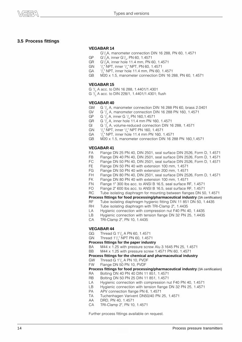
3.5 Process fittings
VEGABAR 14G1/2A, manometer connection DIN 16 288, PN 60, 1.4571
GP G1/2A, inner G1/4, PN 60, 1.4571GR G1/2A, inner hole 11.4 mm, PN 60, 1.4571GN 1/2" NPT, inner 1/4" NPT, PN 60, 1.4571GA 1/2" NPT, inner hole 11.4 mm, PN 60, 1.4571GB M20 x 1.5, manometer connection DIN 16 288, PN 60, 1.4571
VEGABAR 15G 1/2 A acc. to DIN 16 288, 1.4401/1.4301G 1/2 A acc. to DIN 228/1, 1.4401/1.4301; flush
VEGABAR 40GM G 1/2 A, manometer connection DIN 16 288 PN 60, brass 2.0401GV G 1/2 A, manometer connection DIN 16 288 PN 160, 1.4571GP G 1/2 A, inner G 1/4 PN 160,1.4571GR G 1/2 A, inner hole 11.4 mm PN 160, 1.4571GI G 1/2 A, volume-reduced connection DIN 16 288, 1.4571GN 1/2" NPT, inner 1/4" NPT PN 160, 1.4571GA 1/2" NPT, inner hole 11.4 mm PN 160, 1.4571GB M20 x 1.5, manometer connection DIN 16 288 PN 160,1.4571
VEGABAR 41FA Flange DN 25 PN 40, DIN 2501, seal surface DIN 2526, Form D, 1.4571FB Flange DN 40 PN 40, DIN 2501, seal surface DIN 2526, Form D, 1.4571FC Flange DN 50 PN 40, DIN 2501, seal surface DIN 2526, Form D, 1.4571FE Flange DN 50 PN 40 with extension 100 mm, 1.4571FG Flange DN 50 PN 40 with extension 200 mm, 1.4571FH Flange DN 80 PN 40, DIN 2501, seal surface DIN 2526, Form D, 1.4571FK Flange DN 80 PN 40 with extension 100 mm, 1.4571FN Flange 1" 300 lbs acc. to ANSI B 16.5, seal surface RF, 1.4571FO Flange 2" 600 lbs acc. to ANSI B 16.5, seal surface RF, 1.4571RC Tube isolating diaphragm for mounting between flanges DN 50, 1.4571Process fittings for food processing/pharmaceutical industry (3A certification)RF Tube isolating diaphragm hygienic fitting DIN 11 851 DN 50, 1.4435RH Tube isolating diaphragm with TRI-Clamp 2", 1.4435LA Hygienic connection with compression nut F40 PN 40, 1.4435LB Hygienic connection with tension flange DN 32 PN 25, 1.4435CA TRI-Clamp 2", PN 10, 1.4435
VEGABAR 44GG Thread G 11/2 A PN 60, 1.4571GN Thread 11/2" NPT PN 60, 1.4571Process fittings for the paper industryBA M44 x 1.25 with pressure screw Alu 3.1645 PN 25, 1.4571BB M44 x 1.25 with pressure screw 1.4571 PN 60, 1.4571Process fittings for the chemical and pharmaceutical industryGW Thread G 11/2 A PN 10, PVDFFW Flange DN 50 PN 10, PVDFProcess fittings for food processing/pharmaceutical industry (3A certification)RA Bolting DN 40 PN 40 DIN 11 851, 1.4571RB Bolting DN 50 PN 25 DIN 11 851, 1.4571LA Hygienic connection with compression nut F40 PN 40, 1.4571LB Hygienic connection with tension flange DN 32 PN 25, 1.4571PA APV connection flange PN 6, 1.4571TA Tuchenhagen Varivent DN50/40 PN 25, 1.4571AA DRD, PN 40, 1.4571CA TRI-Clamp 2", PN 10, 1.4571
Further process fittings available on request.

Process pressure transmitters 15
Types and versions
3.6 Approvals and certificates
VEGABAR 40 … 44 process pressure transmitters with different approvals are available for use in Ex areas.
VEGABAR 40 VEGABAR 41 VEGABAR 44 VEGADIS 10
Ex Zone 2 • • •
StEx Zone 10 • •
Ship approval 1) • • •
CENELEC EEx ia IIC • • • •
ATEX II 1G EEx ia IIC • • •
ATEX II 2G EEx d ia IIC 1) • • •
1) not with Profibus PA version
If for certain applications the use of approved instruments is required, the respective official documents (test reports, testcertificates and conformity certificates) must be noted. They are supplied with the respective instrument.
CE conformityVEGABAR process pressure transmitters meet the requirements of EMC (89/336/EWG) and NSR (73/23/EWG). Conformityhas been judged acc. to the following standards:EMC Emission EN 50 081 - 1: 1992
Susceptibility EN 50 082 - 2: 1995NSR EN 61 010 - 1: 1993
NAMUR regulationsVEGABAR 14 … 44 process pressure transmitters (4 … 20 mA and HART® version) meet the NAMUR regulations NE 21 andNE 43.VEGABAR 40 … 44 process pressure transmitters (Profibus PA version) meet the NAMUR regulations NE 21, May 1993.

16 Process pressure transmitters
Technical data
4 Technical data
4.1 VEGABAR 14
Mechanical data
Materials, wetted parts
Process fitting stainless steel 1.4571Diaphragm sapphire ceramic® (99.9 % Oxydeceramic)Seal measuring cell Viton
Materials, non-wetted parts
Housing brass nickel-platedPlug/Cable outlet PA
Weight
VEGABAR 14 approx. 450 g
Adjustment elements (only with plug version)
Trim potentiometer for zero point adjustment
Adjustment ranges (only with plug version)
Zero point adjustment ± 5 %
Electrical data
Supply and signal circuit
Supply voltage 12 … 30 V DCPermissible residual ripple USS � 1 VOutput signal 3 … 23 mACurrent limitation approx. 23 mARise time 1 ms (0 % – 63 %)Connection cable 2-wireMax. permissible load depending on the supply voltage
(see load diagram)
12
300
600
675
18 24 30
Load
RLt
otal in
Ohm
Supply voltage UH in Volt
Connection
Plug- cable entry Pg 9 (for cable ø 4.5 … 7 mm)- screw terminals for wire cross section up to 2.5 mm2
Direct cable outlet
Protective measures
Protection 1)
- with plug connection DIN 43 560 A IP 65- with direct cable outlet IP 67Protection class IIIOvervoltage category III
1) To maintain the housing protection, a sealsuitable for the cable should be used in thecable entry. If the seal used does not fit thecable, it should be exchanged for a suitableone.
Process pressure transmitters 17
Technical data
1) Relating to the nominal measuring range.2) Acc. to IEC 770, point 6.1.2 relating to the
nominal measuring range.
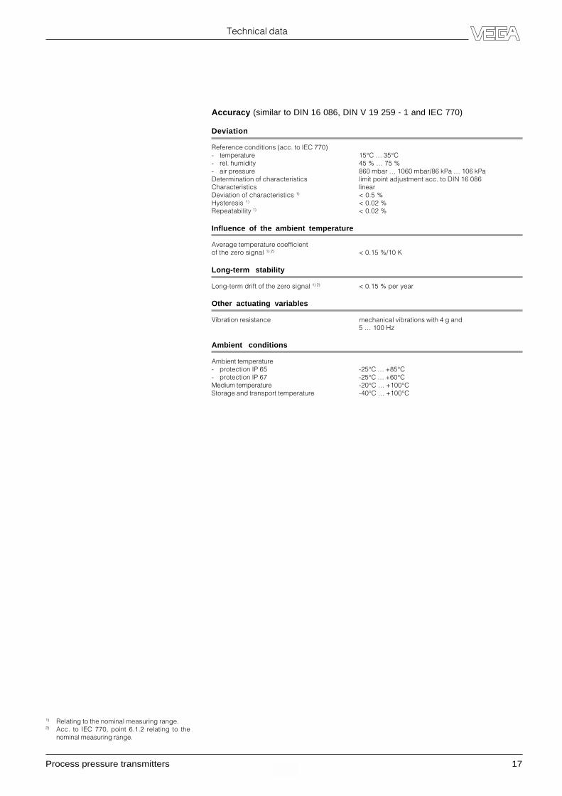
Accuracy (similar to DIN 16 086, DIN V 19 259 - 1 and IEC 770)
Deviation
Reference conditions (acc. to IEC 770)- temperature 15°C … 35°C- rel. humidity 45 % … 75 %- air pressure 860 mbar … 1060 mbar/86 kPa … 106 kPaDetermination of characteristics limit point adjustment acc. to DIN 16 086Characteristics linearDeviation of characteristics 1) < 0.5 %Hysteresis 1) < 0.02 %Repeatability 1) < 0.02 %
Influence of the ambient temperature
Average temperature coefficientof the zero signal 1) 2) < 0.15 %/10 K
Long-term stability
Long-term drift of the zero signal 1) 2) < 0.15 % per year
Other actuating variables
Vibration resistance mechanical vibrations with 4 g and5 … 100 Hz
Ambient conditions
Ambient temperature- protection IP 65 -25°C … +85°C- protection IP 67 -25°C … +60°CMedium temperature -20°C … +100°CStorage and transport temperature -40°C … +100°C

18 Process pressure transmitters
Technical data
Mechanical data
Materials, wetted parts
Process fitting stainless steel 1.4404Diaphragm- internal sensor element stainless steel 1.4404- flush version stainless steel 1.4401
Materials, non-wetted parts
Housing- internal sensor element stainless steel 1.4404- flush version stainless steel 1.4301Plug PA
Weight
VEGABAR 15 approx. 300 g
Electrical data
Supply and signal circuit
Supply voltage 10 … 30 V DCPermissible residual ripple USS � 1 VOutput signal 3.5 … 23 mACurrent limitation approx. 28 mARise time < 4 ms (0 % – 63 %)Connection cable 2-wireMax. permissible load depending on the supply voltage
(see load diagram)
4.2 VEGABAR 15
Connection
Cable entry Pg 9 (DIN 43 650)
Protective measures
Protection 1) IP 65Protection class IIIOvervoltage category III
10
500
1000
15 20 25 300
Load
RLt
otal in
Ohm
Supply voltage UH in Volt
1) To maintain the housing protection, a sealsuitable for the cable should be used in thecable entry. If the seal used does not fit thecable, it should be exchanged for a suitableone.
Process pressure transmitters 19
Technical data
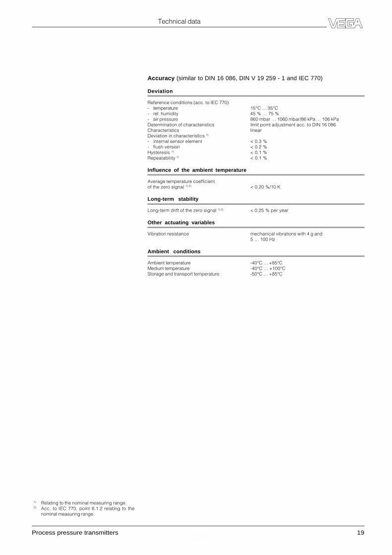
Accuracy (similar to DIN 16 086, DIN V 19 259 - 1 and IEC 770)
Deviation
Reference conditions (acc. to IEC 770)- temperature 15°C … 35°C- rel. humidity 45 % … 75 %- air pressure 860 mbar … 1060 mbar/86 kPa … 106 kPaDetermination of characteristics limit point adjustment acc. to DIN 16 086Characteristics linearDeviation in characteristics 1)
- internal sensor element < 0.3 %- flush version < 0.2 %Hysteresis 1) < 0.1 %Repeatability 1) < 0.1 %
Influence of the ambient temperature
Average temperature coefficientof the zero signal 1) 2) < 0.20 %/10 K
Long-term stability
Long-term drift of the zero signal 1) 2) < 0.25 % per year
Other actuating variables
Vibration resistance mechanical vibrations with 4 g and5 … 100 Hz
Ambient conditions
Ambient temperature -40°C … +85°CMedium temperature -40°C … +100°CStorage and transport temperature -50°C … +85°C
1) Relating to the nominal measuring range.2) Acc. to IEC 770, point 6.1.2 relating to the
nominal measuring range.
20 Process pressure transmitters
4.3 VEGABAR 40
Technical data
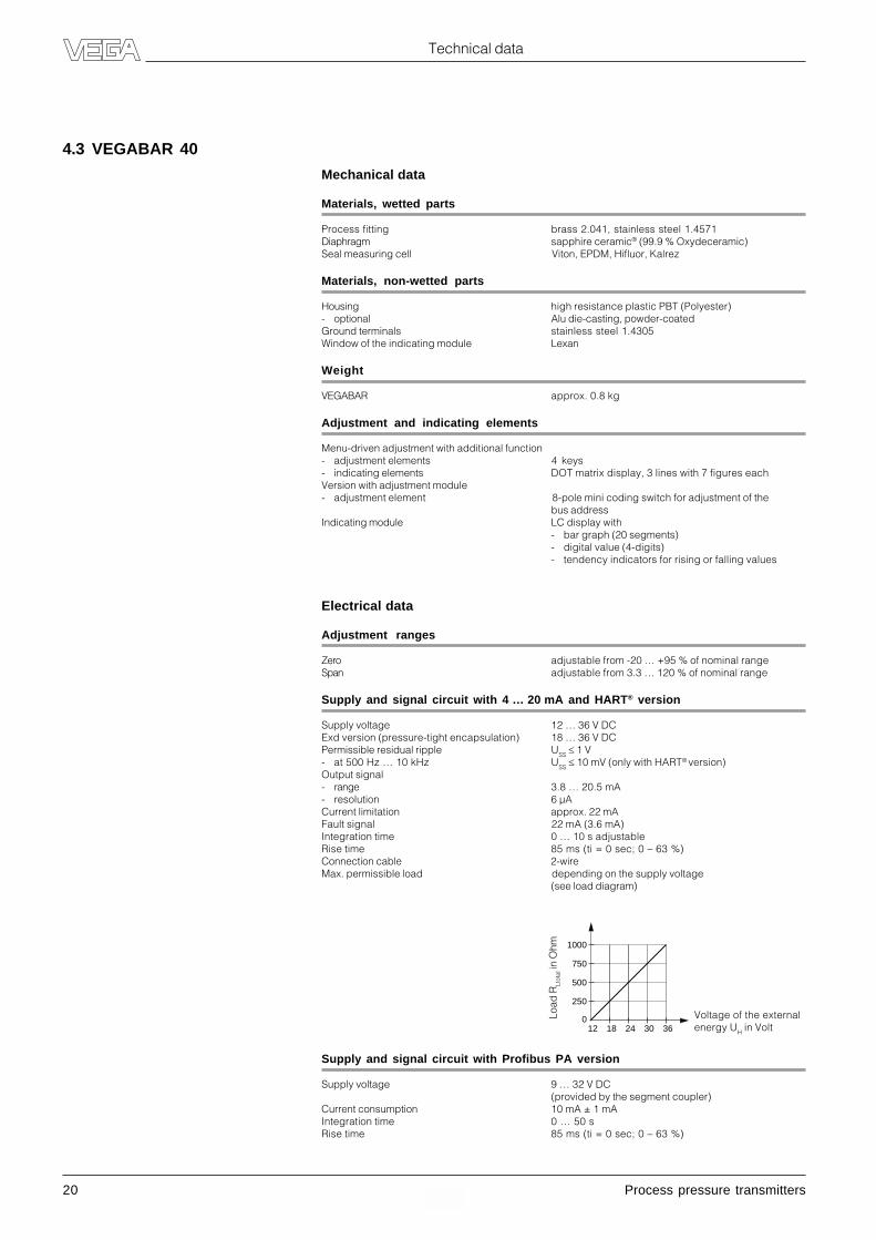
Mechanical data
Materials, wetted parts
Process fitting brass 2.041, stainless steel 1.4571Diaphragm sapphire ceramic® (99.9 % Oxydeceramic)Seal measuring cell Viton, EPDM, Hifluor, Kalrez
Materials, non-wetted parts
Housing high resistance plastic PBT (Polyester)- optional Alu die-casting, powder-coatedGround terminals stainless steel 1.4305Window of the indicating module Lexan
Weight
VEGABAR approx. 0.8 kg
Adjustment and indicating elements
Menu-driven adjustment with additional function- adjustment elements 4 keys- indicating elements DOT matrix display, 3 lines with 7 figures eachVersion with adjustment module- adjustment element 8-pole mini coding switch for adjustment of the
bus addressIndicating module LC display with
- bar graph (20 segments)- digital value (4-digits)- tendency indicators for rising or falling values
Electrical data
Adjustment ranges
Zero adjustable from -20 … +95 % of nominal rangeSpan adjustable from 3.3 … 120 % of nominal range
Supply and signal circuit with 4 … 20 mA and HART® version
Supply voltage 12 … 36 V DCExd version (pressure-tight encapsulation) 18 … 36 V DCPermissible residual ripple USS � 1 V- at 500 Hz … 10 kHz USS � 10 mV (only with HART® version)Output signal- range 3.8 … 20.5 mA- resolution 6 µACurrent limitation approx. 22 mAFault signal 22 mA (3.6 mA)Integration time 0 … 10 s adjustableRise time 85 ms (ti = 0 sec; 0 – 63 %)Connection cable 2-wireMax. permissible load depending on the supply voltage
(see load diagram)
12
250
018 24 30 36
500
750
1000
Load
RLt
otal in
Ohm
Voltage of the externalenergy UH in Volt
Supply and signal circuit with Profibus PA version
Supply voltage 9 … 32 V DC(provided by the segment coupler)
Current consumption 10 mA ± 1 mAIntegration time 0 … 50 sRise time 85 ms (ti = 0 sec; 0 – 63 %)
Process pressure transmitters 21
Technical data
1) To maintain the housing protection, a sealsuitable for the cable should be used in thecable entry. If the seal used does not fit thecable, it should be exchanged for a suitableone.
2) Relating to the nominal range.3) In the compensated temperature range of
0°C … +80°C, reference temperature 20°C.4) Acc. to IEC 770, point 6.1.2 relating to the
nominal range.
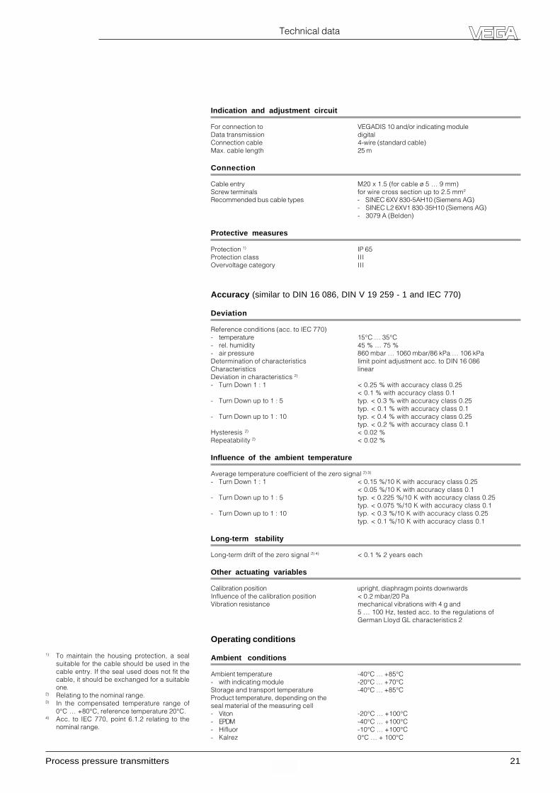
Indication and adjustment circuit
For connection to VEGADIS 10 and/or indicating moduleData transmission digitalConnection cable 4-wire (standard cable)Max. cable length 25 m
Connection
Cable entry M20 x 1.5 (for cable ø 5 … 9 mm)Screw terminals for wire cross section up to 2.5 mm2
Recommended bus cable types - SINEC 6XV 830-5AH10 (Siemens AG)- SINEC L2 6XV1 830-35H10 (Siemens AG)- 3079 A (Belden)
Protective measures
Protection 1) IP 65Protection class IIIOvervoltage category III
Accuracy (similar to DIN 16 086, DIN V 19 259 - 1 and IEC 770)
Deviation
Reference conditions (acc. to IEC 770)- temperature 15°C … 35°C- rel. humidity 45 % … 75 %- air pressure 860 mbar … 1060 mbar/86 kPa … 106 kPaDetermination of characteristics limit point adjustment acc. to DIN 16 086Characteristics linearDeviation in characteristics 2)
- Turn Down 1 : 1 < 0.25 % with accuracy class 0.25< 0.1 % with accuracy class 0.1
- Turn Down up to 1 : 5 typ. < 0.3 % with accuracy class 0.25typ. < 0.1 % with accuracy class 0.1
- Turn Down up to 1 : 10 typ. < 0.4 % with accuracy class 0.25typ. < 0.2 % with accuracy class 0.1
Hysteresis 2) < 0.02 %Repeatability 2) < 0.02 %
Influence of the ambient temperature
Average temperature coefficient of the zero signal 2) 3)
- Turn Down 1 : 1 < 0.15 %/10 K with accuracy class 0.25< 0.05 %/10 K with accuracy class 0.1
- Turn Down up to 1 : 5 typ. < 0.225 %/10 K with accuracy class 0.25typ. < 0.075 %/10 K with accuracy class 0.1
- Turn Down up to 1 : 10 typ. < 0.3 %/10 K with accuracy class 0.25typ. < 0.1 %/10 K with accuracy class 0.1
Long-term stability
Long-term drift of the zero signal 2) 4) < 0.1 % 2 years each
Other actuating variables
Calibration position upright, diaphragm points downwardsInfluence of the calibration position < 0.2 mbar/20 PaVibration resistance mechanical vibrations with 4 g and
5 … 100 Hz, tested acc. to the regulations ofGerman Lloyd GL characteristics 2
Operating conditions
Ambient conditions
Ambient temperature -40°C … +85°C- with indicating module -20°C … +70°CStorage and transport temperature -40°C … +85°CProduct temperature, depending on theseal material of the measuring cell- Viton -20°C … +100°C- EPDM -40°C … +100°C- Hifluor -10°C … +100°C- Kalrez 0°C … + 100°C

22 Process pressure transmitters
Technical data
4.4 VEGABAR 41Mechanical data
Materials, wetted parts
Process fitting stainless steel 1.4571Diaphragm stainless steel 1.4571, Hastelloy C276, Tantalum,
PTFE foil on 1.4571Extension stainless steel 1.4571
Materials, non-wetted parts
Housing high resistance plastic PBT (Polyester)- optional Alu die casting, powder-coatedGround terminals stainless steel 1.4305Window of the indicating module Lexan
Weights
VEGABAR approx. 0.8 … 8 kg (depending on the isolatingsystem)
Adjustment and indicating elements
Adjustment of the basic functions 2 keys, 1 rotary switchMenu-driven adjustment with additional function- adjustment elements 4 keys- indicating elements DOT matrix display, 3 lines with 7 figures eachIndicating module LC display with
- bar graph (20 segment)- digital value (4-digit)- tendency indicators for rising or falling values
Electrical data
Adjustment ranges
Zero adjustable from -20 … +95 % of nominal rangeSpan adjustable from 3.3 … 120 % of nominal range
Supply and signal circuit with 4 … 20 mA and HART® version
Supply voltage 12 … 36 V DCExd version (pressure-tight encapsulation) 18 … 36 V DCPermissible residual ripple USS � 1 V- at 500 Hz … 10 kHz USS � 10 mV (only with HART® version)Output signal- range 3.8 … 20.5 mA- resolution 6 µACurrent limitation approx. 22 mAFault signal 22 mA (3.6 mA)Integration time 0 … 10 s adjustableRise time 85 ms (ti = 0 sec; 0 – 63 %)Connection cable 2-wireMax. permissible load depending on the supply voltage
(see load diagram)
12
250
018 24 30 36
500
750
1000
Load
RLt
otal in
Ohm
Voltage of the externalenergy UH in Volt
Supply and signal circuit with Profibus PA version
Supply voltage 9 … 32 V DC(provided by the segment coupler)
Current consumption 10 mA ± 1 mAIntegration time 0 … 50 sRise time 85 ms (ti = 0 sec; 0 – 63 %)

Process pressure transmitters 23
Technical data
Indication and adjustment circuit
For connection to VEGADIS 10 and/or indicating moduleData transmission digitalConnection cable 4-wire (standard cable)Max. cable length 25 m
Connection
Cable entry M20 x 1.5 (for cable ø 5 … 10 mm)Screw terminals for wire cross section up to 2.5 mm2
Protective measures
Protection 1) IP 65Protection class IIIOvervoltage category III
Accuracy (similar to DIN 16 086, DIN V 19 259 - 1 and IEC 770)
Deviation
Reference conditions (acc. to IEC 770)- temperature 15°C … 35°C- rel. humidity 45 % … 75 %- air pressure 860 mbar … 1060 mbar/86 kPa … 106 kPaDetermination of characteristics limit point adjustment acc. to DIN 16 086Characteristics linearDeviation in characteristics 2)
- Turn Down 1 : 1 < 0.25 % with accuracy class 0.25< 0.1 % with accuracy class 0.1
- Turn Down up to 1 : 5 typ. < 0.3 % with accuracy class 0.25typ. < 0.1 % with accuracy class 0.1
- Turn Down up to 1 : 10 typ. < 0.4 % with accuracy class 0.25typ. < 0.2 % with accuracy class 0.1
Hysteresis 2) < 0.02 %Repeatability 2) < 0.02 %
Influence of the ambient temperature
Average temperature coefficient of the zero signal 2) 3)
- Turn Down 1 : 1 < 0.15 %/10 K with accuracy class 0.25< 0.05 %/10 K with accuracy class 0.1
- Turn Down up to 1 : 5 typ. < 0.225 %/10 K with accuracy class 0.25typ. < 0.075 %/10 K with accuracy class 0.1
- Turn Down up to 1 : 10 typ. < 0.3 %/10 K with accuracy class 0.25typ. < 0.1 %/10 K with accuracy class 0.1
Long-term stability
Long-term drift of the zero signal 2) 4) < 0.1 % 2 years each
Other actuating variables
Calibration position upright, diaphragm points downwardsInfluence of the installation position < 0.2 mbar/20 PAVibration resistance mechanical vibrations with 4 g and
5 … 100 Hz, tested acc. to the regulations ofGerman Lloyd GL regulation 2
Operating conditions
Ambient conditions
Ambient temperature -40°C … +85°C- with indicating module -20°C … +70°CStorage and transport temperature -40°C … +85°C
1) To maintain the housing protection, a sealsuitable for the cable should be used in thecable entry. If the seal used does not fit thecable, it should be exchanged for a suitableone.
2) Relating to the nominal range.3) In the compensated temperature range of
0°C … +80°C, reference temperature 20°C.4) Acc. to IEC 770, point 6.1.2 relating to the
nominal range.
24 Process pressure transmitters
Technical data
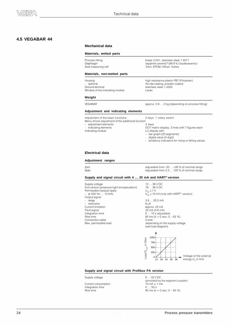
4.5 VEGABAR 44
Mechanical data
Materials, wetted parts
Process fitting brass 2.041, stainless steel 1.4571Diaphragm sapphire ceramic® (99.9 % Oxydeceramic)Seal measuring cell Viton, EPDM, Hifluor, Kalrez
Materials, non-wetted parts
Housing high resistance plastic PBT (Polyester)- optional Alu die casting, powder-coatedGround terminal stainless steel 1.4305Window of the indicating module Lexan
Weight
VEGABAR approx. 0.8 … 2 kg (depending on process fitting)
Adjustment and indicating elements
Adjustment of the basic functions 2 keys, 1 rotary switchMenu-driven adjustment of the additional function- adjustment elements 4 keys- indicating elements DOT matrix display, 3 lines with 7 figures eachIndicating module LC display with
- bar graph (20 segments)- digital value (4-digit)- tendency indicators for rising or falling values
Electrical data
Adjustment ranges
Zero adjustable from -20 … +95 % of nominal rangeSpan adjustable from 3.3 … 120 % of nominal range
Supply and signal circuit with 4 … 20 mA and HART® version
Supply voltage 12 … 36 V DCExd version (pressure-tight encapsulation) 18 … 36 V DCPermissible residual ripple USS � 1 V- at 500 Hz … 10 kHz USS � 10 mV (only with HART® version)Output signal- range 3.8 … 20.5 mA- resolution 6 µACurrent limitation approx. 22 mAFault signal 22 mA (3.6 mA)Integration time 0 … 10 s adjustableRise time 85 ms (ti = 0 sec; 0 – 63 %)Connection cable 2-wireMax. permissible load depending on the supply voltage
(see load diagram)
12
250
018 24 30 36
500
750
1000
Load
RLt
otal in
Ohm
Voltage of the externalenergy UH in Volt
Supply and signal circuit with Profibus PA version
Supply voltage 9 … 32 V DC(provided by the segment coupler)
Current consumption 10 mA ± 1 mAIntegration time 0 … 50 sRise time 85 ms (ti = 0 sec; 0 – 63 %)
Process pressure transmitters 25
Technical data
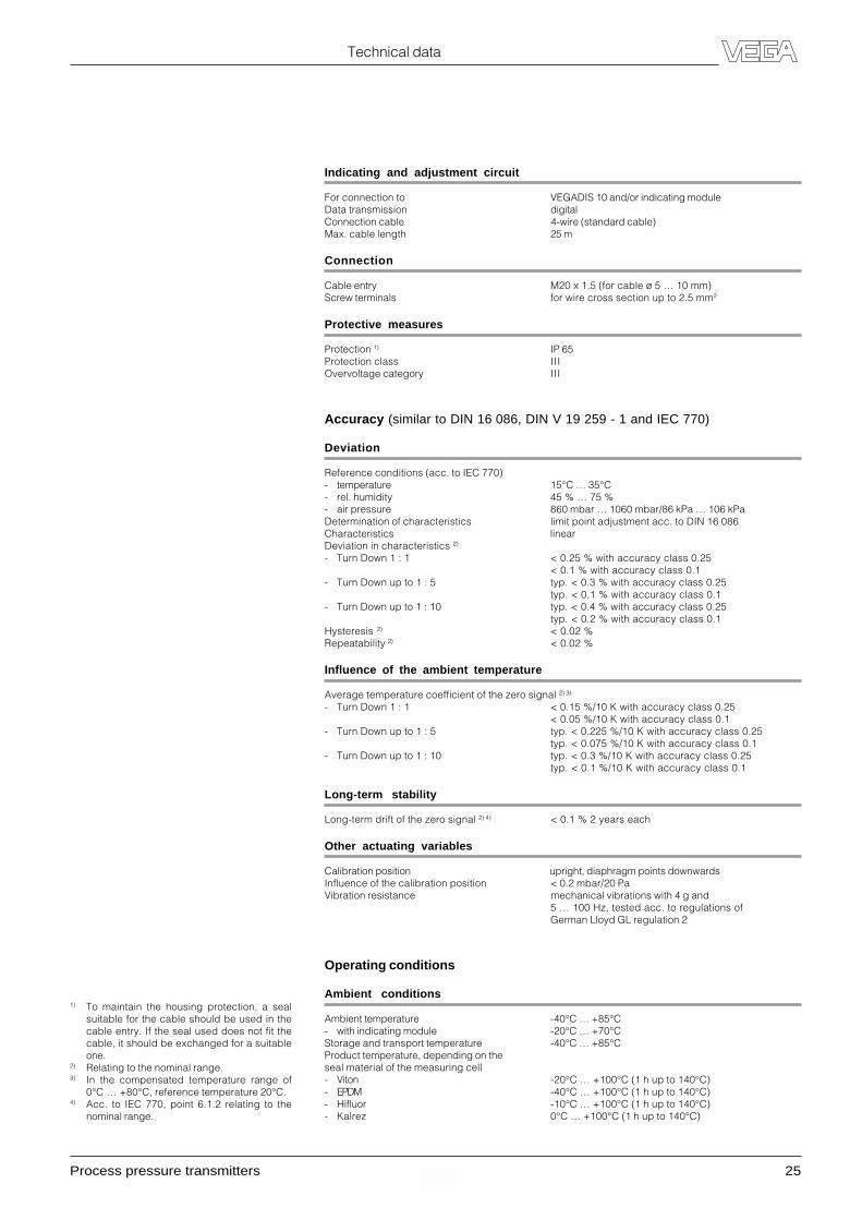
Indicating and adjustment circuit
For connection to VEGADIS 10 and/or indicating moduleData transmission digitalConnection cable 4-wire (standard cable)Max. cable length 25 m
Connection
Cable entry M20 x 1.5 (for cable ø 5 … 10 mm)Screw terminals for wire cross section up to 2.5 mm2
Protective measures
Protection 1) IP 65Protection class IIIOvervoltage category III
Accuracy (similar to DIN 16 086, DIN V 19 259 - 1 and IEC 770)
Deviation
Reference conditions (acc. to IEC 770)- temperature 15°C … 35°C- rel. humidity 45 % … 75 %- air pressure 860 mbar … 1060 mbar/86 kPa … 106 kPaDetermination of characteristics limit point adjustment acc. to DIN 16 086Characteristics linearDeviation in characteristics 2)
- Turn Down 1 : 1 < 0.25 % with accuracy class 0.25< 0.1 % with accuracy class 0.1
- Turn Down up to 1 : 5 typ. < 0.3 % with accuracy class 0.25typ. < 0,1 % with accuracy class 0.1
- Turn Down up to 1 : 10 typ. < 0.4 % with accuracy class 0.25typ. < 0.2 % with accuracy class 0.1
Hysteresis 2) < 0.02 %Repeatability 2) < 0.02 %
Influence of the ambient temperature
Average temperature coefficient of the zero signal 2) 3)
- Turn Down 1 : 1 < 0.15 %/10 K with accuracy class 0.25< 0.05 %/10 K with accuracy class 0.1
- Turn Down up to 1 : 5 typ. < 0.225 %/10 K with accuracy class 0.25typ. < 0.075 %/10 K with accuracy class 0.1
- Turn Down up to 1 : 10 typ. < 0.3 %/10 K with accuracy class 0.25typ. < 0.1 %/10 K with accuracy class 0.1
Long-term stability
Long-term drift of the zero signal 2) 4) < 0.1 % 2 years each
Other actuating variables
Calibration position upright, diaphragm points downwardsInfluence of the calibration position < 0.2 mbar/20 PaVibration resistance mechanical vibrations with 4 g and
5 … 100 Hz, tested acc. to regulations ofGerman Lloyd GL regulation 2
Operating conditions
Ambient conditions
Ambient temperature -40°C … +85°C- with indicating module -20°C … +70°CStorage and transport temperature -40°C … +85°CProduct temperature, depending on theseal material of the measuring cell- Viton -20°C … +100°C (1 h up to 140°C)- EPDM -40°C … +100°C (1 h up to 140°C)- Hifluor -10°C … +100°C (1 h up to 140°C)- Kalrez 0°C … +100°C (1 h up to 140°C)
1) To maintain the housing protection, a sealsuitable for the cable should be used in thecable entry. If the seal used does not fit thecable, it should be exchanged for a suitableone.
2) Relating to the nominal range.3) In the compensated temperature range of
0°C … +80°C, reference temperature 20°C.4) Acc. to IEC 770, point 6.1.2 relating to the
nominal range.

26 Process pressure transmitters
Technical data
4.6 VEGADIS 10
General
Housing material plastic PBTIndication window glassBreather facility PTFE filter element 1)
Weight approx. 350 g
Adjustment and indicating elements
Adjustment of the basic functions 2 keys, 1 rotary switchMenu-driven adjustment with additional function- adjustment elements 4 keys- indicating elements DOT matrix display, 3 lines with 7 figures eachIndicating module LC display with
- bar graph (20 segments)- digital value (4-digit)- tendency indicators for rising or falling values
Connection
Cable entry Pg 13.5 (for cable ø 5 … 10 mm)Screw terminals for wire cross sections up to 2.5 mm2
Adjustment circuit
Connection to VEGABAR process pressure transmittersConnection cable 4-wire (standard cable)Cable length max. 25 m
Ambient conditions
Ambient temperature- VEGADIS 10 -40°C … +85°C- indicating module -20°C … +70°CStorage and transport temperature -40°C … +85°C
Electrical protective measures
Protection 2) IP 65
CE conformity
VEGADIS 10 meets the protective regulations of EMC (89/336/EWG) and NSR (73/23/EWG). Theconformity has been judged acc. to the following standards:EMC Emission EN 50 081 - 1
Susceptibility EN 50 082 - 2NSR EN 61 010 - 1
1) Air permeable and moisture offering.2) To maintain the housing protection, a seal
suitable for the cable should be used in thecable entry. If the seal used does not fit thecable, it should be exchanged for a suitableone.
Process pressure transmitters 27
Technical data
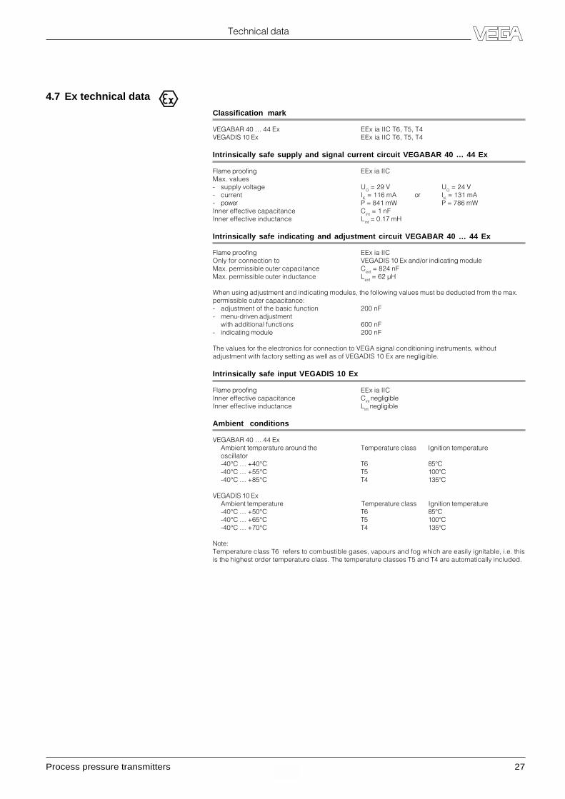
4.7 Ex technical data
Classification mark
VEGABAR 40 … 44 Ex EEx ia IIC T6, T5, T4VEGADIS 10 Ex EEx ia IIC T6, T5, T4
Intrinsically safe supply and signal current circuit VEGABAR 40 … 44 Ex
Flame proofing EEx ia IICMax. values- supply voltage UO = 29 V UO = 24 V- current IK = 116 mA or IK = 131 mA- power P = 841 mW P = 786 mWInner effective capacitance Cint = 1 nFInner effective inductance Lint = 0.17 mH
Intrinsically safe indicating and adjustment circuit VEGABAR 40 … 44 Ex
Flame proofing EEx ia IICOnly for connection to VEGADIS 10 Ex and/or indicating moduleMax. permissible outer capacitance Cext = 824 nFMax. permissible outer inductance Lext = 62 µH
When using adjustment and indicating modules, the following values must be deducted from the max.permissible outer capacitance:- adjustment of the basic function 200 nF- menu-driven adjustment
with additional functions 600 nF- indicating module 200 nF
The values for the electronics for connection to VEGA signal conditioning instruments, withoutadjustment with factory setting as well as of VEGADIS 10 Ex are negligible.
Intrinsically safe input VEGADIS 10 Ex
Flame proofing EEx ia IICInner effective capacitance Cint negligibleInner effective inductance Lint negligible
Ambient conditions
VEGABAR 40 … 44 ExAmbient temperature around the Temperature class Ignition temperatureoscillator-40°C … +40°C T6 85°C-40°C … +55°C T5 100°C-40°C … +85°C T4 135°C
VEGADIS 10 ExAmbient temperature Temperature class Ignition temperature-40°C … +50°C T6 85°C-40°C … +65°C T5 100°C-40°C … +70°C T4 135°C
Note:Temperature class T6 refers to combustible gases, vapours and fog which are easily ignitable, i.e. thisis the highest order temperature class. The temperature classes T5 and T4 are automatically included.

28 Process pressure transmitters
Technical data
4.8 Dimensions
Housing dimensions VEGABAR 14 with process fittings
25
15
20
¼" NPT
½" NPT
36
25
20
ø11,4
½" NPT
36
25
ø3
M20x1,5
36
5
ø6
20
G ¼
G ½ A
ø17,5
3
31
20
ø11,4
G ½ A
31
ø17,5
325
G ½ A
36
5
SW 27
ø3ø6
GP GR
GN GA GB
45
124
25
36
153
49,5
ø38
Version with plug connection
Version with direct cable outlet
Process pressure transmitters 29
Technical data
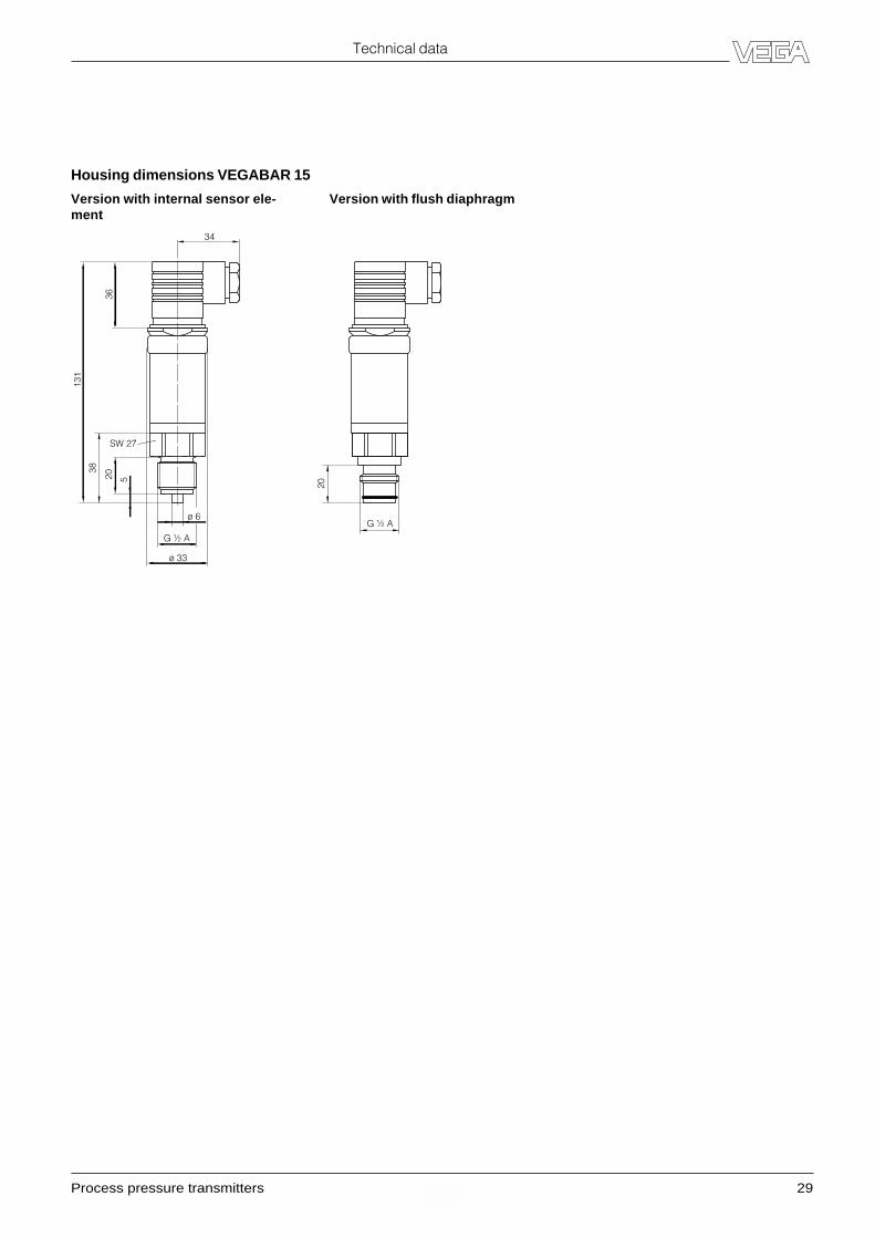
Housing dimensions VEGABAR 15
20 5
ø 6
G ½ A
ø 33
SW 27
38
34
36
131
G ½ A
20
Version with internal sensor ele-ment
Version with flush diaphragm

30 Process pressure transmitters
72
85
~76
82
~76
M20x1,5
90
82
M20x1,5
~76
82
90
½" NPT
156
78
Housing dimensions VEGABAR 40/41/44 (without process fittings)
Ground con-nection
Ground con-nection
Ground con-nection
Versionplastic PBT
VersionAlu die casting
VersionAlu die casting inEExd
without indicating module with indicating module
Technical data
Process pressure transmitters 31
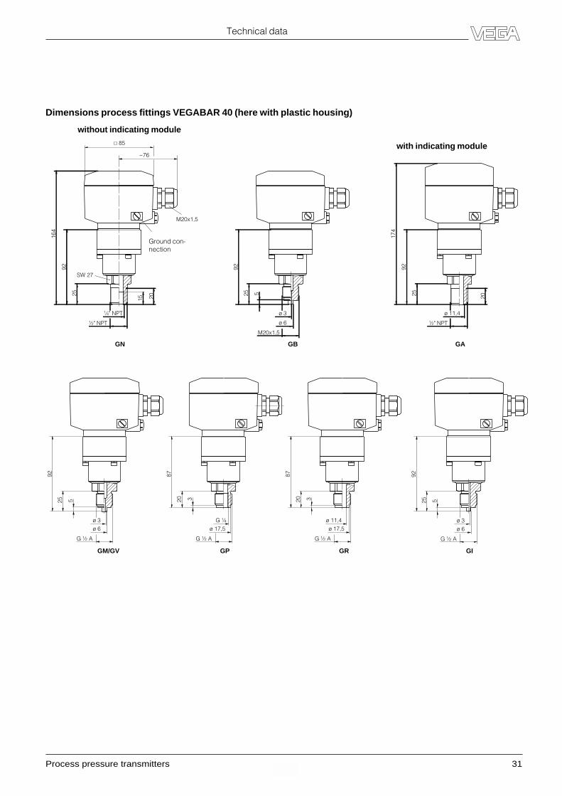
25 5
92
GM/GV
ø 6ø 3
G ½ A
25 5
92
GI
ø 6
ø 3
G ½ A
20 3
87
ø 17,5G ¼
G ½ A
GP
20 3
87
ø 17,5ø 11,4
G ½ A
GR
25
174
92
GA
20
ø 11,4
½" NPT
85
~76
M20x1,5
GN
25
15 20
SW 27
¼" NPT
½" NPT
164
92
25 5
92
GB
ø 6
ø 3
M20x1,5
Technical data
Dimensions process fittings VEGABAR 40 (here with plastic housing)
without indicating module
with indicating module
Ground con-nection
32 Process pressure transmitters
Technical data
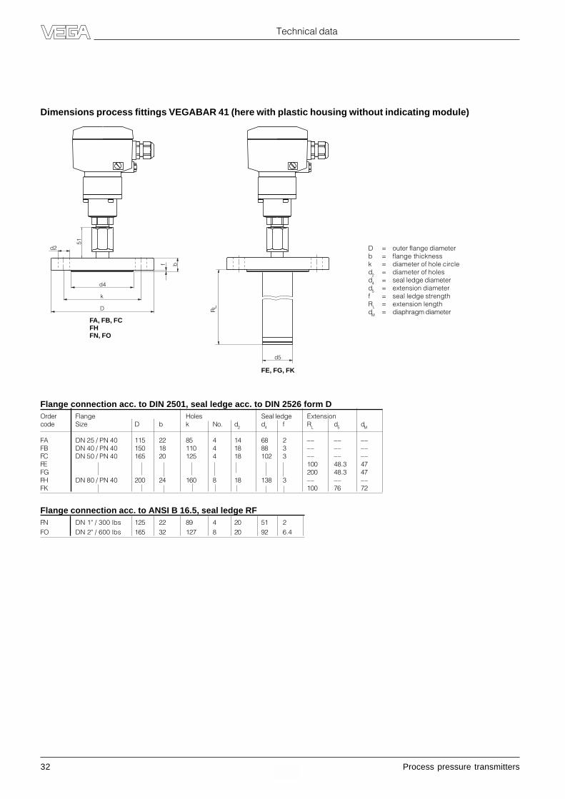
Flange connection acc. to DIN 2501, seal ledge acc. to DIN 2526 form DOrder Flange Holes Seal ledge Extensioncode Size D b k No. d2 d4 f RL d5 dM
FA DN 25 / PN 40 115 22 85 4 14 68 2 –– –– ––FB DN 40 / PN 40 150 18 110 4 18 88 3 –– –– ––FC DN 50 / PN 40 165 20 125 4 18 102 3 –– –– ––FE 100 48.3 47FG 200 48.3 47FH DN 80 / PN 40 200 24 160 8 18 138 3 –– –– ––FK 100 76 72
Flange connection acc. to ANSI B 16.5, seal ledge RFFN DN 1" / 300 lbs 125 22 89 4 20 51 2FO DN 2" / 600 lbs 165 32 127 8 20 92 6.4
Dimensions process fittings VEGABAR 41 (here with plastic housing without indicating module)
D = outer flange diameterb = flange thicknessk = diameter of hole circled2 = diameter of holesd4 = seal ledge diameterd5 = extension diameterf = seal ledge strengthRL = extension lengthdM = diaphragm diameter
d2
d4
k
D
f
51
b
FA, FB, FCFHFN, FO
d5
RL
FE, FG, FK
Process pressure transmitters 33
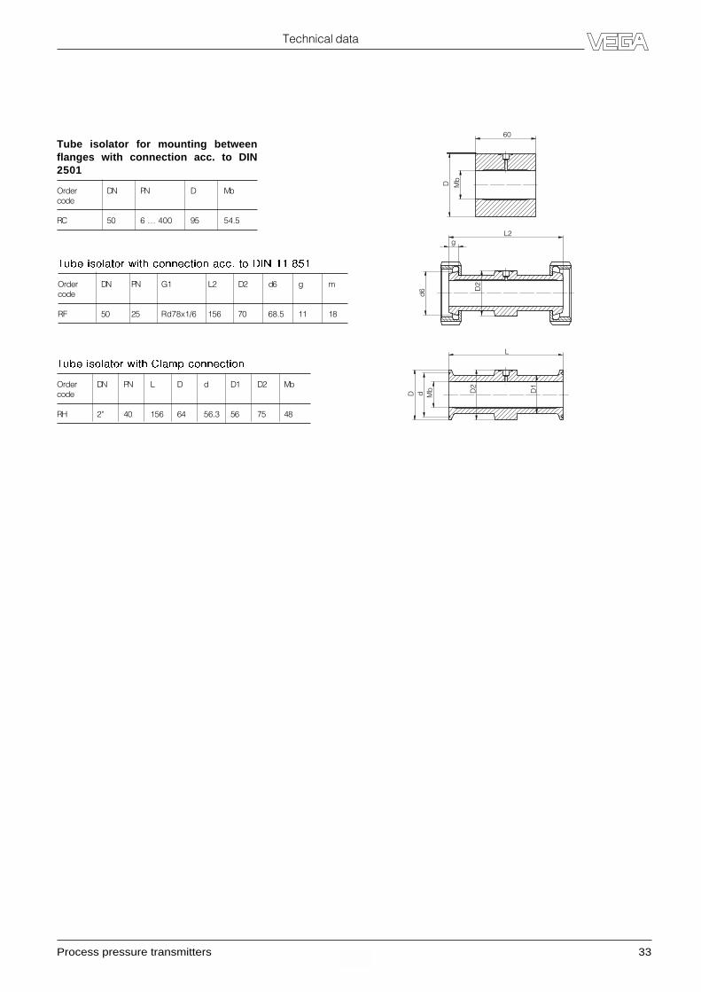
D d Mb D2
D1
L
d6 D
2
L2g
D Mb
60
Tube isolator with connection acc. to DIN 11 851
Order DN PN G1 L2 D2 d6 g mcode
RF 50 25 Rd78x1/6 156 70 68.5 11 18
Tube isolator for mounting betweenflanges with connection acc. to DIN2501
Order DN PN D Mbcode
RC 50 6 … 400 95 54.5
Tube isolator with Clamp connection
Order DN PN L D d D1 D2 Mbcode
RH 2" 40 156 64 56.3 56 75 48
Technical data

34 Process pressure transmitters
SW 60
49
24,5
121
G 1½ A
ø 55
GG
85
~76
M20x1,549
,5
25
G 1½ A
ø 60
GW
49
25
1½ " NPT
131
GN
LB CALABA/BB
SW 46
51,5
21
M44 x 1,25
39
82
ø 78
34,5
82
ø 90
64
ø 64
TA RA RB AA
64
ø 78
64
ø 92
64
ø 65,8
ø 105
SW 46
64
ø 84
PA FW
SW 46
64
ø 100
51,5
ø 100
ø 165
20,5
Technical data
Dimensions process fittings VEGABAR 44 (here plastic housing)
without indicating module
with indicating module
Ground con-nection

Process pressure transmitters 35
Technical data
Dimensions VEGADIS 10
without indicating module
with indicating module
M20x1,5
118
108
135
38 72
85
ø5
82
36 Process pressure transmitters
Mounting
5 Mounting
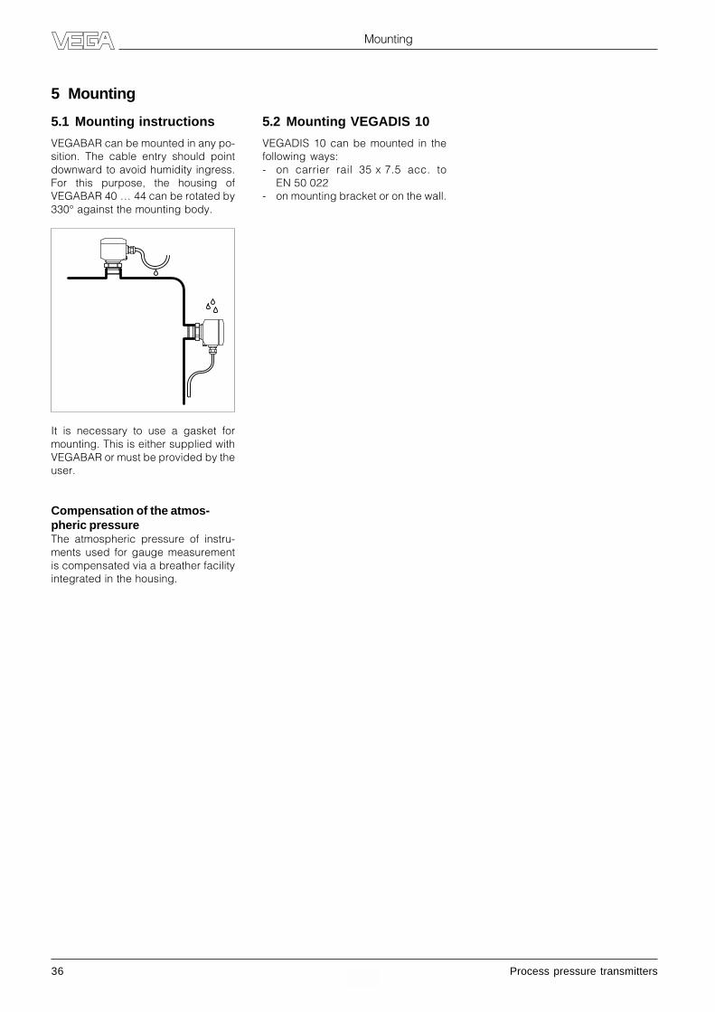
It is necessary to use a gasket formounting. This is either supplied withVEGABAR or must be provided by theuser.
Compensation of the atmos-pheric pressureThe atmospheric pressure of instru-ments used for gauge measurementis compensated via a breather facilityintegrated in the housing.
5.1 Mounting instructions
VEGABAR can be mounted in any po-sition. The cable entry should pointdownward to avoid humidity ingress.For this purpose, the housing ofVEGABAR 40 … 44 can be rotated by330° against the mounting body.
5.2 Mounting VEGADIS 10
VEGADIS 10 can be mounted in thefollowing ways:- on carrier rail 35 x 7.5 acc. to
EN 50 022- on mounting bracket or on the wall.

Process pressure transmitters 37
Electrical connection
6.1 Connection instructions
The electronics in VEGABAR requiresa supply voltage of 12 … 36 V DC. It isprovided in two-wire technology, i.e.supply voltage and current signal arelooped via the same two-wire cable tothe terminals.
This external energy is provided via aseparate power supply unit:- power supply unit, e.g. VEGASTAB
690- processing unit with integral DC-
current source (e.g. active DCS-input)
- VEGAMET or VEGADIS 371
Make sure that the external supply isreliably isolated from the mains cir-cuits acc. to DIN VDE 0106, part 101.The above mentioned VEGA instru-ments meet this requirement and pro-tection class III is hence ensured.
The external supply must provide aterminal voltage of at least 12 V to thetransmitter. The actual terminal volt-age on the transmitter depends on thefollowing factors:- output voltage of the external power
supply under nominal load.- electrical resistances of the con-
nected instruments in the circuit(see connected instruments, loadresistance).
6 Electrical connection
Note the following instructions forelectrical connection:- The connection must be made acc.
to the local installation standards(e.g. in Germany acc. to the VDE-regulations).
- The terminal voltage must not ex-ceed 36 V to avoid damage to theelectronics.
- The electrical connection is pro-vided with a reverse polarity protec-tion.
- The wiring between VEGABAR andpower supply can be made withstandard two-wire cable.
- If strong electromagnetic interfer-ences are expected, screened ca-ble is recommended. The screen-ing must be earthed at one side onthe sensor.
- If overvoltages are expected, werecommend the installation of VEGAovervoltage arresters.
- A seal suitable for the cable must beused in the cable entry.
- With instrument version EExd (pres-sure-tight encapsulation) screenedcable must be used for the instru-ment connection. Observe themounting regulations.
Connection instructions forProfibus PA instruments
The electronics in process pressuretransmitters for Profibus PA requires asupply voltage of 9 … 32 V DC. Thesupply voltage and the digital outputsignal are led via the same two-wireconnection cable to the terminals.The external energy is provided by asegment coupler.
Note the following instructions forelectrical connection:- The connection must be made acc.
to the local installation standards(e.g. in Germany acc. to the VDE-regulations).
- The electrical connection musthave a protective measure againstpolarity reversal.
- The connection of field instrumentsis generally made via T-adapters onstubs.
- Screened cable is recommendedfor connection (cable types seechapter "Technical data"). Theshielding must be grounded on bothends (on the T-adapter and on theconnection housing).
- For use in Ex areas, the installationregulations must be observed.
38 Process pressure transmitters
Electrical connection
1) If a screened cable is used, the screen should be connected to function ground in the terminal box and the ground terminal on the housing exterior groundedaccording to the instructions. Both terminals are connected to each other in the housing.
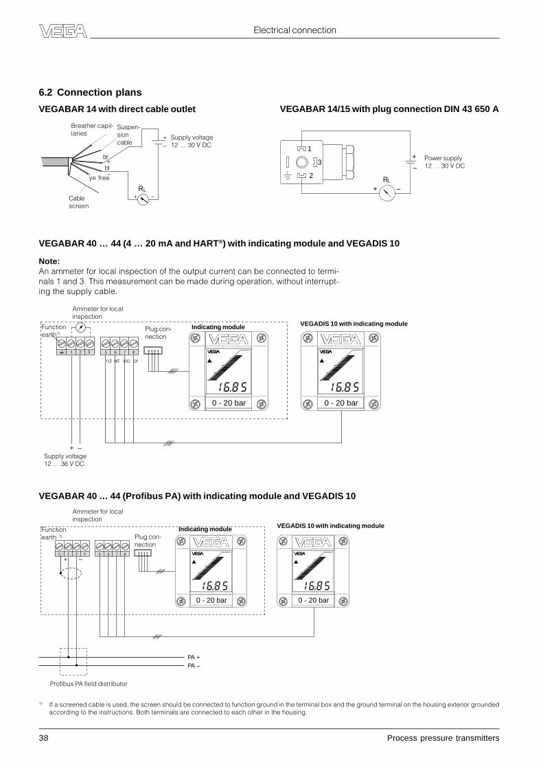
VEGABAR 40 … 44 (4 … 20 mA and HART®) with indicating module and VEGADIS 10
0 - 20 bar
8765321
–+
0 - 20 bar
Functionearth1)
Ammeter for localinspection
Supply voltage12 … 36 V DC
VEGADIS 10 with indicating moduleIndicating modulePlug con-nection
rd wt vio or
VEGABAR 40 … 44 (Profibus PA) with indicating module and VEGADIS 10
Note:An ammeter for local inspection of the output current can be connected to termi-nals 1 and 3. This measurement can be made during operation, without interrupt-ing the supply cable.
8765321
PA –
–
PA +
+
0 - 20 bar 0 - 20 bar
Functionearth 1)
Ammeter for localinspection
VEGADIS 10 with indicating moduleIndicating modulePlug con-nection
Profibus PA field distributor
+
+
+
–
–
–
RL
Breather capil-laries
Suspen-sioncable
Cablescreen
br
bl
ye free 2
3
1
+ –RL
+
–
VEGABAR 14/15 with plug connection DIN 43 650 A
6.2 Connection plans
VEGABAR 14 with direct cable outlet
Supply voltage12 … 30 V DC
Power supply12 … 30 V DC
Process pressure transmitters 39
+ – –
1 2 3
+
–
~
1 2 3
+
–
+ – –
Electrical connection
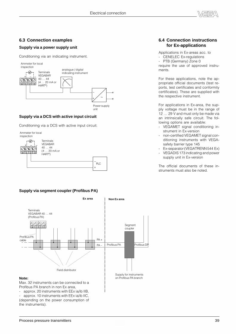
6.3 Connection examples
Supply via a power supply unit
Conditioning via an indicating instrument.
Supply via a DCS with active input circuit
Conditioning via a DCS with active input circuit.
Ammeter for localinspection
PLC
Ammeter for localinspection
analogue / digitalindicating instrument
Power supplyunit
TerminalsVEGABAR40 … 44(4 … 20 mA orHART®)
6.4 Connection instructionsfor Ex-applications
Applications in Ex-areas acc. to- CENELEC Ex-regulations- PTB (Germany) Zone 0require the use of approved instru-ments.
For these applications, note the ap-propriate official documents (test re-ports, test certificates and conformitycertificates). These are supplied withthe respective instrument.
For applications in Ex-area, the sup-ply voltage must be in the range of12 … 29 V and must only be made viaan intrinsically safe circuit. The fol-lowing options are available:- VEGAMET signal conditioning in-
strument in Ex-version- non-certified VEGAMET signal con-
ditioning instruments with VEGA-safety barrier type 145
- Ex-separator (VEGATRENN 544 Ex)- VEGADIS 173 indicating and power
supply unit in Ex-version
The official documents of these in-struments must also be noted.
Supply via segment coupler (Profibus PA)
1 2 3Segmentcoupler
Profibus PAcable
TerminalsVEGABAR 40 … 44(Profibus PA)
Field distributor
Profibus PA Profibus DP
Ex area Non Ex area
Supply for instrumentson Profibus PA branchNote:
Max. 32 instruments can be connected to aProfibus PA branch in non Ex area,- approx. 20 instruments with EEx ia/ib IIB,- approx. 10 instruments with EEx ia/ib IIC,(depending on the power consumption ofthe instruments).
TerminalsVEGABAR40 … 44(4 … 20 mA orHART®)
PA +
PA –
40 Process pressure transmitters
+ ± ±
1 2 3
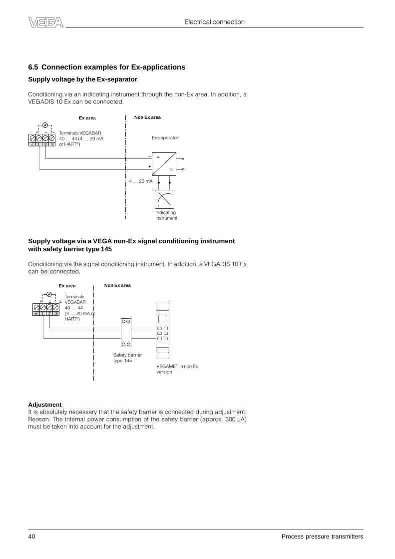
6.5 Connection examples for Ex-applications
Supply voltage by the Ex-separator
Conditioning via an indicating instrument through the non-Ex area. In addition, aVEGADIS 10 Ex can be connected.
Supply voltage via a VEGA non-Ex signal conditioning instrumentwith safety barrier type 145
Conditioning via the signal conditioning instrument. In addition, a VEGADIS 10 Excan be connected.
AdjustmentIt is absolutely necessary that the safety barrier is connected during adjustment.Reason: The internal power consumption of the safety barrier (approx. 300 µA)must be taken into account for the adjustment.
Electrical connection
+ – –
1 2 3
+
– =
~
4 … 20 mA
Indicatinginstrument
Ex separator
Ex area Non Ex area
Safety barriertype 145
Ex area
VEGAMET in non Exversion
Non Ex area
Terminals VEGABAR40 … 44 (4 … 20 mAor HART®)
TerminalsVEGABAR40 … 44(4 … 20 mA orHART®)
Process pressure transmitters 41
Hot steam measurement with VEGABAR 40
7 Hot steam measurement with VEGABAR 40
Condensatepipe
Condensate
Hot steam
Condensatepipe
Condensate
Hot steam
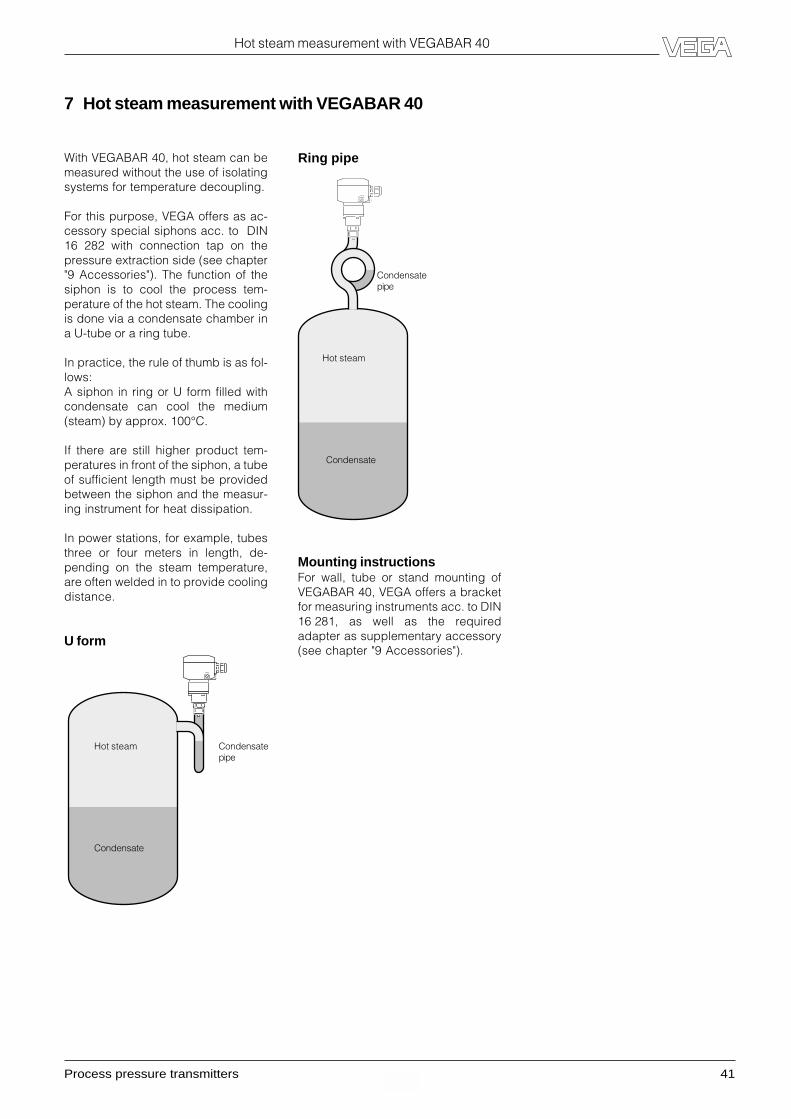
With VEGABAR 40, hot steam can bemeasured without the use of isolatingsystems for temperature decoupling.
For this purpose, VEGA offers as ac-cessory special siphons acc. to DIN16 282 with connection tap on thepressure extraction side (see chapter"9 Accessories"). The function of thesiphon is to cool the process tem-perature of the hot steam. The coolingis done via a condensate chamber ina U-tube or a ring tube.
In practice, the rule of thumb is as fol-lows:A siphon in ring or U form filled withcondensate can cool the medium(steam) by approx. 100°C.
If there are still higher product tem-peratures in front of the siphon, a tubeof sufficient length must be providedbetween the siphon and the measur-ing instrument for heat dissipation.
In power stations, for example, tubesthree or four meters in length, de-pending on the steam temperature,are often welded in to provide coolingdistance.
U form
Ring pipe
Mounting instructionsFor wall, tube or stand mounting ofVEGABAR 40, VEGA offers a bracketfor measuring instruments acc. to DIN16 281, as well as the requiredadapter as supplementary accessory(see chapter "9 Accessories").

42 Process pressure transmitters
Pressure transmitters with isolating diaphragms
8 Pressure transmitters with isolating diaphragms
8.1 General information onisolating diaphragms
Isolating diaphragms transfer themeasured pressure of the substanceto the pressure transmitter, if for cer-tain reasons, the pressure transmittershould or cannot come into contactwith the measured substance.
Isolating diaphragms and pressuretransmitters form a complex measur-ing system, the accuracy of which isinfluenced by many factors. The opti-mum dimensioning for solving an in-dividual measuring problem can onlybe carried out if the operating condi-tions are exactly known.
The goal of this presentation is toshow the problem involved with iso-lating systems and to give basic infor-mation on possible solutions.
8.2 Applications
There are many reasons why a sepa-rator between measured substanceand pressure transmitter might benecessary:• The measured substance is corro-
sive. The sensor element cannot beprotected effectively.
• The measured substance is highlyviscous. The often inevitable deadzones of the pressure transmittercause measuring problems.
• The measured substance crystal-lizes, especially in dead zones.
• The measured substance polymer-izes. Connection tubes to the pres-sure transmitter can clog.
• The measured substance is hetero-geneous, e.g. fibrous; buildup andunmixing are caused in dead zones.
• The measured substance has a veryhigh temperature. An unwanted tem-perature increase is caused in thepressure transmitter.
• The measurement location is unfa-vourable. Due to space reasons,the pressure transmitter cannot bemounted or read correctly. The pres-sure transmitter is connected to theisolating diaphragm via a capillaryline so that mounting in a more fa-vourable place is possible.
• Hygienic regulations must be ob-served for the measured substance.Bacterial growth can result in cor-ners which are difficult to clean.
8.3 Function
The function of an isolating dia-phragm is best shown in a diagram.The pressure to be detected is trans-ferred via the separating diaphragmand the oil filling to the sensor ele-ment.
CERTEC®
Oil filling for pres-sure transmission
Separating diaphragm
Construction of an isolation diaphragm
Process pressure transmitters 43
Pressure transmitters with isolating diaphragms
8.4 Selection criteria
Isolating systems have a characteris-tic temperature reaction which cansubstantially influence the measure-ment. To reduce this influence to aminimum, some important factorsshould be considered.
First of all, the diaphragm diameter
should be as large as possible. Rea-son: Diaphragms with small diam-eters are more rigid than those withlarger diameters. The temperaturedependent expansion of the isolatingliquid is better compensated by a dia-phragm with larger diameter (larger =more elastic) as the diaphragm com-pensates a part of the isolation liquidexpansion. This selection criterion isof course limited by the required proc-ess connection.
The second possibility for optimisingthe temperature reaction is the thick-ness of the separating diaphragm.Here is valid: the thicker the dia-phragm, the worser the temperaturecoefficient! Usual diaphragm thick-nesses are between 50 µm and100 µm. However the mechanicalruggedness should be always takeninto account, as a thin diaphragm canbe easily damaged by carelessnessor substances containing solids.
The selection of the fill fluid (e.g. sili-cone oil, water-glycerine) also offersthe possibility to influence the tem-perature reaction, as the liquids havedifferent temperature expansion coef-ficients. The characteristics of differ-ent fill fluids are discussed in detaillater on.
The necessary oil volume for fillingthe isolating system must also be con-sidered. However, the mechanicaldesign is usually such that the re-quired oil volume is already mini-mised and therefore no realisticoptimisation possibilities exist.
In general, the selection of the sepa-
rating diaphragm material also of-fers a means for optimisation. In prac-tice, however, it is a matter of fact thatthe diaphragm material is primarilydetermined by the product compat-ibility.
Additional characteristic propertiesresult from the design of the isolatingsystem.
Quick temperature changes willreach the sensor element consider-ably damped. This eliminates thesometimes unfavourable temperatureshock reaction of the CERTEC® celland also reduces temperature-re-lated ageing effects. One disadvan-tage of the temperature decoupling isthat the read-out temperature valuescorrespond only in a few cases to theactual product temperature.
Another aspect is the noticeable re-duction of dynamic pressure peaksby the transmitting oil, which also hasa positive effect on the reliability of thepressure transmitter.
8.5 Error calculation
The influence of an isolating systemis primarily determined by the tem-perature of the isolating liquid.
The total temperature error is the sumof the temperature dependencies ofthe pressure transmitter and the iso-lating system.
TKTot = TKIsolating system + TKPressure transmitter
Example:
The selected pressure transmitter has- a nominal range of 0 … 1 bar and- a TK of 0.05 %/10 K (see technical
data).This corresponds to a TKPressure transmitter
of 0.5 mbar/10K.
The isolating diaphragm used has atemperature influence of 2.7 mbar/10 K
TKTot = TKIsolating diaphragm + TKPressure transmit.
= 2.7 mbar/10K + 0.5 mbar/10 K= 3.2 mbar /10 K
The determined total temperature er-ror corresponds therefore to 0.32 %/10 K!
Due to these dependencies, there arelimitations on the available nominalmeasuring ranges, depending on thenominal width of the isolating system.This limitation results from the factthat the temperature errors of the iso-lating systems must be seen as abso-lute values and therefore have a con-siderable influence on the total errorsmall nominal measuring ranges.
Nom. width of the Nom. meas. rangesisolating system in bar
0 – 0.4 0 – 1…60
DN 25 –– x
DN 40/1" –– x
DN 50/2" –– x
DN 80/3" x x
44 Process pressure transmitters
Pressure transmitters with isolating diaphragms
To reduce the total error of the pressure transmitter to a minimum, it is necessary to use a pressure transmitter in the bestavailable accuracy class (especially for small measuring ranges as well as small nominal widths!).
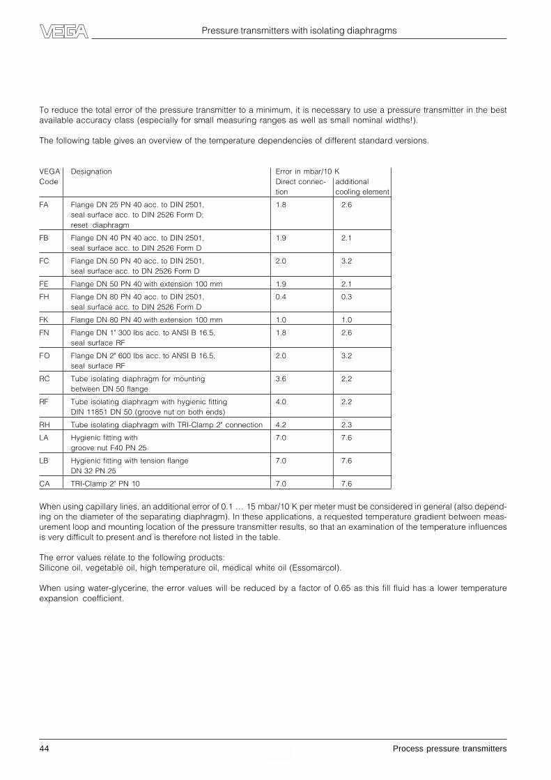
The following table gives an overview of the temperature dependencies of different standard versions.
VEGA Designation Error in mbar/10 KCode Direct connec- additional
tion cooling element
FA Flange DN 25 PN 40 acc. to DIN 2501, 1.8 2.6seal surface acc. to DIN 2526 Form D;reset diaphragm
FB Flange DN 40 PN 40 acc. to DIN 2501, 1.9 2.1seal surface acc. to DIN 2526 Form D
FC Flange DN 50 PN 40 acc. to DIN 2501, 2.0 3.2seal surface acc. to DN 2526 Form D
FE Flange DN 50 PN 40 with extension 100 mm 1.9 2.1
FH Flange DN 80 PN 40 acc. to DIN 2501, 0.4 0.3seal surface acc. to DIN 2526 Form D
FK Flange DN 80 PN 40 with extension 100 mm 1.0 1.0
FN Flange DN 1" 300 lbs acc. to ANSI B 16.5, 1.8 2.6seal surface RF
FO Flange DN 2" 600 lbs acc. to ANSI B 16.5, 2.0 3.2seal surface RF
RC Tube isolating diaphragm for mounting 3.6 2.2between DN 50 flange
RF Tube isolating diaphragm with hygienic fitting 4.0 2.2DIN 11851 DN 50 (groove nut on both ends)
RH Tube isolating diaphragm with TRI-Clamp 2" connection 4.2 2.3
LA Hygienic fitting with 7.0 7.6groove nut F40 PN 25
LB Hygienic fitting with tension flange 7.0 7.6DN 32 PN 25
CA TRI-Clamp 2" PN 10 7.0 7.6
When using capillary lines, an additional error of 0.1 … 15 mbar/10 K per meter must be considered in general (also depend-ing on the diameter of the separating diaphragm). In these applications, a requested temperature gradient between meas-urement loop and mounting location of the pressure transmitter results, so that an examination of the temperature influencesis very difficult to present and is therefore not listed in the table.
The error values relate to the following products:Silicone oil, vegetable oil, high temperature oil, medical white oil (Essomarcol).
When using water-glycerine, the error values will be reduced by a factor of 0.65 as this fill fluid has a lower temperatureexpansion coefficient.

Process pressure transmitters 45
Pressure transmitters with isolating diaphragms
Isolating systems extend the producttemperature range of pressure trans-mitters considerably. Therefore makesure that the ambient temperature onthe pressure transmitter does not ex-ceed the max. specified value. In criti-cal applications, the use of a coolingelement or a capillary must be takeninto consideration.
The application temperatures are lim-ited by the max. permissible ambienttemperature of the pressure transmit-ter (85°C) as well as the different ther-mal characteristics of the isolatingliquids.
In addition, take into considerationthat when pressures below 1 barabs
occur, the isolating liquids boil evenat low temperatures. The followinglimit values result thereof:
Isolating liquid permissible temperature range
Pressure > 1 barabs Pressure < 1 barabs
Pressure > 0 barrel Pressure < 0 barrel
Silicone oil -40°C … +130°C -40°C … +130°C
Silicone oil and cooling element -40°C … +200°C -40°C … + 130°C
Silicone oil and capillaries (1 m) -40°C … +200°C -40°C … +130°C
Vegetable oil -10°C … +130°C -10°C … +130°C
Vegetable oil and cooling element -10°C … +250°C -10°C … +130°C
High temperature oil and cooling element -10°C … +400°C -10°C … +200°C
High temperature oil and capillaries (1 m) -10°C … +400°C -10°C … +200°C
Medical white oil (Essomarcol) -40°C … 130°C -40°C … +130°C
Water-glycerine -40°C … +130°C -40°C … +130°C
8.6 Application temperatures

46 Process pressure transmitters
Accessories
9 Accessories
Cut-off valve form Awith tension sleeve
- stainless steel ................................ Article no. 2.20057- steel ................................................ Article no. 2.20056
Cut-off valve form Bwith rotary sleeve and shaftfor measuring instrument holder
- stainless steel ................................ Article no. 2.20059- steel ................................................ Article no. 2.20058
Cut-off valve form B-AS12with rotary sleeve and shaftfor measuring instrument holder;with cutting ring screwing
- stainless steel ................................ Article no. 2.20219- steel ................................................ Article no. 2.20218
Manometer connection tubestraight;with welding connection and tension sleeve
- stainless steel ................................ Article no. 2.24462- steel ................................................ Article no. 2.24463
ø 6310
020
ø 6
79
G ½
G ½
G ½
100
28
117
18
ø 26 h11
G ½
G ½
100
2,6ø 20
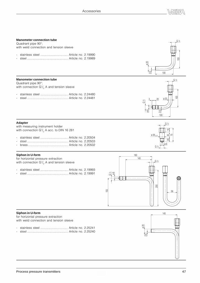
Process pressure transmitters 47
Accessories
Manometer connection tubeQuadrant pipe 90°;with weld connection and tension sleeve
- stainless steel ................................ Article no. 2.19990- steel ................................................ Article no. 2.19989
Manometer connection tubeQuadrant pipe 90°;with connection G1/2 A and tension sleeve
- stainless steel ................................ Article no. 2.24480- steel ................................................ Article no. 2.24481
Adapterwith measuring instrument holderwith connection G1/2 A acc. to DIN 16 281
- stainless steel ................................ Article no. 2.20504- steel ................................................ Article no. 2.20503- brass ............................................... Article no. 2.20502
Siphon in U-formfor horizontal pressure extractionwith connection G1/2 A and tension sleeve
- stainless steel ................................ Article no. 2.19993- steel ................................................ Article no. 2.19991
Siphon in U-formfor horizontal pressure extractionwith weld connection and tension sleeve
- stainless steel ................................ Article no. 2.25241- steel ................................................ Article no. 2.25240
G ½
1002,6
ø 20
100
G ½
100
2,6
ø 20 100
203
ø 6
G ½
G ½
56
200
155
ø 6
180145
G ½
145
ø 20
2,6
G ½
ø 26 h11
1975
2030
ø 6G ½
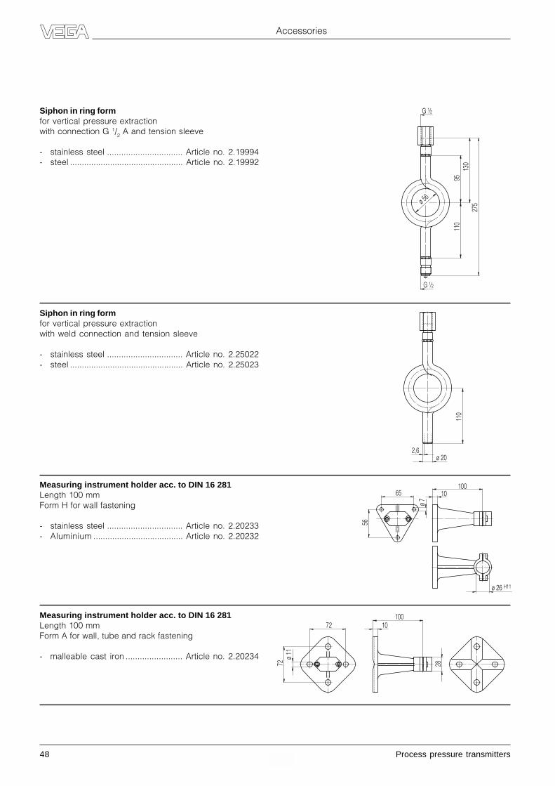
48 Process pressure transmitters
Accessories
Siphon in ring formfor vertical pressure extractionwith connection G 1/2 A and tension sleeve
- stainless steel ................................ Article no. 2.19994- steel ................................................ Article no. 2.19992
Siphon in ring formfor vertical pressure extractionwith weld connection and tension sleeve
- stainless steel ................................ Article no. 2.25022- steel ................................................ Article no. 2.25023
Measuring instrument holder acc. to DIN 16 281Length 100 mmForm H for wall fastening
- stainless steel ................................ Article no. 2.20233- Aluminium ...................................... Article no. 2.20232
Measuring instrument holder acc. to DIN 16 281Length 100 mmForm A for wall, tube and rack fastening
- malleable cast iron ........................ Article no. 2.20234
G ½
G ½
ø 56
275
130
9511
0ø 20
2,611
0
10010
ø 7
56
65
ø 26 H11
28
10010
ø 11
72
72

Process pressure transmitters 49
Accessories
Welded socket thread G 11/2 A (GG)
- of stainless steel 1.4571 ...................... Article no. 2.21993- of steel .................................................. Article no. 2.8239
- seal Klingersil ...................................... Article no. 2.4191- seal lead .............................................. Article no. 2.3437- seal copper coated ............................. Article no. 2.2503
Welded socket M44x1.25 (BA, BB)
- of stainless steel 1.4571 ...................... Article no. 2.15986
- seal Viton ............................................. Article no. 2.10491- seal PTFE ............................................. Article no. 2.15185
- welding dummy brass ......................... Article no. 2.18000
- blind stopper 1.4571 ........................... Article no. 2.16098
Welded socket TRI-Clamp 11/2"
- of stainless steel 1.4571 ...................... Article no. 2.14140
Welded socket TRI-Clamp 2" (CA)
- of stainless steel 1.4435 ...................... Article no. 2.10974
- seal EPDM............................................ Article no. 2.10975
Welded socket DRD PN 40 (AA)
- of stainless steel 1.4571 ...................... Article no. 2.10500
- seal PTFE ............................................. Article no. 2.10360
ø65
G1½
1921
ø60
21,5
ø51,6
ø48,6
21
ø125
ø84/4xM10
21,5
ø38,6
ø35,6

50 Process pressure transmitters
Accessories
Welded socket hygienic with groove nut (LA)
- of stainless steel 1.4435 ...................... Article no. 2.23898
- seal EPDM............................................ Article no. 2.17682
- welding dummy 1.4305 ....................... Article no. DMONT.A
- blind stopper 1.4571 ........................... Article no. DMONT.B
Welded socket hygienic with tension flange (LB)
- of stainless steel 1.4571 ...................... Article no. 2.18060
- seal EPDM............................................ Article no. 2.17682
- welding dummy 1.4305 ....................... Article no. DMONT.C
- blind stopper 1.4571 ........................... Article no. DMONT.D
Welded socket, threaded pipe coupling DIN 11 851 DN 40 (RA)
- of stainless steel 1.4404 ...................... Article no. 2.10955
- seal NBR .............................................. Article no. 2.10956
Welded socket, threaded pipe coupling DIN 11 851 DN 50 (RB)
- of stainless steel 1.4404 ...................... Article no. 2.4177
- seal NBR .............................................. Article no. 2.4178
Rd 65 x 1/6
Ø 79,6
40
LA
Ø 72/6xM6
Ø 79,6
40
LB
Ø 38
Ø 43
Rd 65 x 1/6
33
RA
Ø 50
Ø 55
35
RB

Process pressure transmitters 51
Notes

52 Process pressure transmitters2.20 121 / February 2001
ISO 9001
All statements concerning scope of delivery, application, practical use and operating conditions of thesensors and processing systems correspond to the latest information at the time of printing.
Technical data subject to alterations
Great BritainHungaryIndiaIndonesiaIranIsraelItalyJapanKoreaLithuaniaMalaysiaNetherlandsNew ZealandNorwayPeruPhilippinesPoland
PortugalRomaniaRussiaSingaporeSlovakiaSloveniaSouthern AfricaSpainSwedenSwitzerlandTaiwan (ROC)ThailandTurkeyUkraineUSA/Canada/MexicoUnited Arab. EmiratesVenezuela
ArgentinaAustraliaAustriaBelgium/LuxembourgBrazilBulgariaChileChina (PRC)ColumbiaCroatiaCzech RepublicDenmarkEgyptFinlandFranceGermanyGreece
VEGA - Your worldwide sales and service partner
Detailed information on our homepage www.vega.com
VEGA Grieshaber KGAm Hohenstein 11377761 Schiltach/GermanyPhone +49 (0) 7836 50-0Fax +49 (0) 7836 50-201E-Mail [email protected]
Level andPressure


