Download - Product Page - KLEIN REINFORCING

104/10
Che
mic
al &
Cem
ent
Pro
duct
sG
ener
al a
nd T
echn
ical
In
form
atio
nM
isce
llane
ous
Pro
duct
s
Index
Product PageBag Ties .....................................................................................57Bar Lock® L-Series Coupler .........................................................54Bar Lock Structural Steel Connector ..........................................55Bar Lock S/CA-Series Coupler .....................................................54Bar Lock Transition Couplers ......................................................55Chemicals .....................................................................................3Dayton Shear Resistance (DRS) Products ...................................45DBR Coupler...............................................................................26DBR Setting Splice Bar ...............................................................26Double End Anchor ...................................................................50Double-Ended Dowel Bar Splicer ........................................ 14, 15Double-Ended Dowel-In.............................................................13Dowel Bar Replacement Installation ..........................................16Dowel Bar Splicer System .................................................... 11-18Dowel-In ....................................................................................13End Anchorage System ..............................................................49Female End Anchor ....................................................................51Formliners ..................................................................................64Foundation Rail with Studs........................................................45General and Technical Information ..............................................3Headed Dowel Bar Splicer .........................................................17Headed Dowel-In .......................................................................17Hook Bar ....................................................................................27Hooked Dowel Bar Splicer .................................................. 14, 15Hooked Dowel-In .......................................................................13Lockshear Bolt System ...............................................................53Magna Jaw ................................................................................57Male End Anchor .......................................................................52
Product PageMetalStrip ..................................................................................58Miscellaneous Products .............................................................57Plain End Anchor .......................................................................49Position Coupler.........................................................................24QuickStrip ..................................................................................58Rebar Safety Cap .......................................................................57Rebar Supports ..........................................................................61Sleeve-Lock™ Double-Ended Grout Sleeve ................................43Straight Bar ................................................................................27Sure-Guard Rebar Protective Cap ..............................................57Taper-Lock® ................................................................................29Taper-Lock Column Connector ...................................................39Taper-Lock Flange Coupler .........................................................36Taper-Lock End Anchor Disc ..................................................37,38Taper-Lock Positional Coupler ....................................................34Taper-Lock Standard Coupler .....................................................30Taper-Lock Transitional Coupler .................................................32Taper-Lock Weldable Coupler .....................................................40Tie Wire ......................................................................................57Threaded Plastic Setting Plug ....................................................58Threaded Splicing Systems ........................................................11Threaded Steel Setting Plug ......................................................60Transition Coupler ......................................................................21Two-Piece End Anchor ...............................................................50US/MC-SAE Coupler ...................................................................19US/MC-SAE Extended Threaded Splice Bar ................................20US/MC-SAE Standard Threaded Splice Bar ................................20Welding Half Coupler ................................................................22Welding Stud .............................................................................23
Item PageD-42 ....................................55D-45 ....................................55D-46 ....................................55D-48 ....................................55D-49 ....................................55D-50 ....................................26D-51 ....................................27D-52 ....................................27D-54 ....................................27D-55 ....................................56D-56 ....................................56
Item PageD-101 ..................................13D-101-A ........................14, 15D-102 ..................................13D-102-A ........................14, 15D-103 ..................................13D-103-A ........................14, 15D-104 ..................................13D-104-A ........................14, 15D-105 ..................................21D-106 ..................................22D-106-S ...............................23
Item PageD-107 ..................................24D-108 ..................................17D-108-A ..............................17D-110 ..................................19D-111 ..................................20D-112 ..................................20D-140 ..................................43D-158 ..................................48D-250 ............................52, 53D-310 ..................................30D-320 ..................................32
Item PageD-330 ..................................34D-340 ..................................36D-350 ..................................37D-351 .................................. 38D-352 .................................. 39D-360 ..................................40D-410 ..................................43F-72 .....................................60F-74 .....................................60P-154....................................60
Mis
cella
neou
s P
rodu
cts
Lock
shea
r Bol
t Sys
tem
End
Anc
hora
geD
ayto
n S
hear
R
esis
tanc
eTa
per-
Lock
®
Thre
aded
S
plic
ing
Sys
tem
sG
ener
al a
nd T
echn
ical
In
form
atio
n

2 04/10
Notes and Sketches

304/10
General, Technical and Chemical Information
Safety Notes and Product ApplicationDayton Superior strives to ensure that all products supplied from its manufacturing plants meet or exceed the safety
requirements inherent in the proper use of its products. However, the performance of a product can be greatly affected by the manner in which the product is used. It is imperative that the user be instructed in the proper installation and use of the products displayed in this handbook prior to job application.
Product production runs are constantly sampled and tested to assure the user a high standard of quality. Samples are tested in Dayton Superior test facilities or at independent testing laboratories. The safe working loads listed in this handbook were determined from the results of the testing program and other industry sources.
Dayton Superior publishes the safe working loads and the associated minimum safety factors of its products and strongly advises that the minimum safety factors not be compromised. When there are unusual job conditions, the minimum safety factors must be increased by the user. Refer to the provisions of the American National Standards Institute (ANSI A 10.9), the Occupational Safety and Health Administration (OSHA) Act, Part 1910, and the American Concrete Institute (ACI) Recommended Practice for Concrete Formwork (ACI 347) and ACI 318 Building Code when considering product safety factors.
Dayton Superior Technical ServicesThe Dayton Superior technical departments are well staffed with trained personnel to service inquiries, take-offs and
details for the users of Dayton Superior quality splicing accessories.Technical Services: 877.266.7732
Gen
eral
and
Tec
hnic
al
Info
rmat
ion
Construction LiquidsFORM RELEASE AGENTS
Bio-Release EFClean Strip™ (J-1-A)Clean Strip (J-1-A CA)Clean Strip (J-1)Clean Strip (J-1 Light)Clean Strip Citrus (J-1-C)Clean Strip Ultra Light (J-3 Light)Liner Coat (J-4 LC)
BOND BREAKERSCure-Lift EFMaxi Tilt ESure-Lift WB (J-6 WB)Sure-Lift™ (J-6)Sure-Lift FD (J-6 FD)Super Maxi Tilt
CURING COMPOUNDSClear Dissipating Cure EFDay-Chem City White Cure (J-8)Day-Chem Rez Cure (J-11-W)Day-Chem White Pigmented Cure - W (J-9-A)Day-Chem White Pigmented Cure (J-10-W)DSSCC Clear Resin CureDSSCC Resin Cure with DyeDSSCC White Resin CureDSSCC White Wax CRD 300DSSCC White Wax CureWhite Dissipating Cure EF
CURE & SEALSCure & Seal 309 EFCure & Seal 1315 EFDay-Chem Cure & Seal™ (J-21 CP)Day-Chem Cure & Seal 1315 (J-22 U.V.)Day-Chem Cure & Seal U.V. 30% (J-23 U.V.)General Purpose Cure & Seal (J-20 U.V.)Safe Cure & Seal (J-18)Safe Cure & Seal 30% (J-19)
SEALERSDay-Chem Aggre-Gloss™ (J-25)Day-Chem Aggre-Gloss OTC (J-25 OTC)Day-Chem Aggregloss Non-Gloss (J-25 Non-Gloss)Day-Chem Tuf Seal™ (J-35)Day-Chem Tuf Seal OTC (J-35 OTC)Superior Pro Super SealUltra Seal 30 EF
WATER REPELLENTSWeather Worker™ WB (J-26-WB)Weather Worker WB Heavy Duty (J-27-WB)Weather Worker S-40 (J-29)Weather Worker S-100 (J-29-A)Weather Worker S-100 (J-29-WB)
LIQUID DENSIFIERS/Crete-Cure Concentrate (J-12)Day-Chem Sil-Cure™ (J-13)Day-Chem Hardener™ (J-15)Day-Chem Sure Hard™ (J-17)
EPOXIESSure-Anchor Epoxy™ (J-50)Sure-Anchor I™ (J-51)Sure-Anchor All Weather Epoxy (J-51 AW)Resi-Bond™ (J-58)Resi-Bond (J-58 LPL)Sure-Inject (J-56 SLV)Sure Level™ Epoxy (J-57)Sure Grip Epoxy Grout™Turbo Grout EpoxyPoxy-ChockRapid Resin RepairSplash Zone EpoxyRebar Epoxy Spray (J-62)
POLYMER FLOOR COATINGSSpec Cote 100™Spec Cote 100 Clear™Spec Cote 100 CR™Spec Cote Urethane™Spec Cote WB™
SURFACE RETARDERSFace-Off™ Manufactured by GraceTop-Cast™ Manufactured by Grace
JOINT SEALANTS / JOINT FILLERSPerma 230 SLPoxyfil™ (J-52Prison-LocJointfill™
EVAPORATION REDUCERSSure-Film (J-74Sure Film RTU (J-74 RTU
LATEX BONDING AGENTS /Day-Chem Ad Bond (J-40)™Day-Chem CI Ad Bond (J-40CI)LeveLayer™ Bonding Agent (J-42)Superior Concrete Bonder (J-41)
CLEANERS AND STRIPPERSCitrus Peel (J-48)DestructoGreen Bean Clean
LEED / GREENBio-Release EFClear Dissipating Cure EFCure & Seal 1315 EF Cure & Seal 309 EFCure-Lift EFUltra Seal 30 EFWhite Dissipating Cure EF
Construction PowdersCONCRETE REPAIR
Ankertite™Architectural FinishCivil/Structural FPXCivil/Structural VOCM 2000™Day-Chem Perma Patch™HD-25HD-45HD-50™Rapid Resin RepairRe-Crete™ 5 Minute SetRe-Crete 20 Minute SetRe-Crete Light 5 Minute PatchRe-Crete Light 20 Minute PatchPerma Patch V/OPerma Patch F/PPolyfast™ FSPolyfast LPLSnaPlugThin Resurfacer™
DAMPPROOFING/WATERPROOFINGSeal Coat™ 1000Smooth Coat™Water Stop™
GROUTS (NON-SHRINK)1107 Advantage GroutMulti-Purpose GroutSure-Grip Epoxy Grout (J-55 HES)Sure-Grip Ferro GroutSure-Grip Grout Dri-Pak™Sure-Grip High Performance Grout™Sure-Grip UW GroutTurbo Grout™ HP-10Turbo Grout HP-12Turbo Grout LT-12Turbo Grout EpoxyTC 1.4 Geothermal Grout
FLOOR LEVELERSEconoLevel™Level Topping WhiteLeveLayerLevelayer MTLeveLayer Primer J-42™Sure Finish™Sure Patch™Topping™Topping EXT™Underlayment Tool Kit
HARDENERS AND INDUSTRIAL TOPPINGSEmery Non-Slip™Emery Tuff™Emery Tuff TopFerro Tuff™Ferro Tuff LRFerro Tuff Non-RustingFerro Tuff TopQuartz Tuff™

4 04/10
General and Technical Information
Table 1.1 Reinforcing Bar DataReinforcing Bars
Size Designations and Nominal Dimensions
Bar Size Designation Nominal Dimensions Ultimate Minimum Capacity 1.5y
US Metric (mm)
CN (M)
Diameter (inches)
Area (inches2)
Weight (lbs/ft) Pounds
#4 [13] [10] 0.500 0.20 0.688 18,000
#5 [16] [15] 0.625 0.31 1.043 27,900
#6 [19] [20] 0.750 0.44 1.502 39,600
#7 [22] — 0.875 0.60 2.044 54,000
#8 [25] [25] 1.000 0.79 2.670 71,700
#9 [29] [30] 1.128 1.00 3.400 90,000
#10 [32] — 1.270 1.27 4.303 114,300
#11 [36] [35] 1.410 1.56 5.313 140,400
#14 [43] [45] 1.693 2.25 7.650 202,500
#18 [57] [55] 2.257 4.00 13.600 360,000*Rebar size is based on the number of eighths of an inch included in the nominal diameter of the bar.
Note: The nominal dimensions of a deformed rebar are equivalent to those of a plain, round bar having the same weight (mass) per foot (meter) as the deformed rebar.
Nearly all reinforcing bars currently produced in the USA are marked with the numbers 13, 16, etc., to designate bar sizes. These bar size numbers correspond to the traditional designations 4, 5, etc., as shown in the accompanying table.
ACI 318-02 still list the bar sizes traditionally using #3 - #18 designations. The tables in this manual are typically designated #3 [#10] or simply use the traditional designations.
Table 1.2 Mechanical Requirements for Standard ASTM Deformed Reinforcing Bars*
* For the mechanical requirements of rail-steel and axle-steel bars, see ASTM specifications A616 and A617, respectively.1 Minimum yield designation (KSI).2 Yield point or yield strength. See ASTM specifications.3 Test bends 180˚, unless noted otherwise.4 Maximum yield strength 78,000 psi (ASTM A706 only).5 Tensile Strength shall not be less than 1.25 times the actual yield strength (ASTM A706 only).
Gen
eral
and
Tec
hnic
al
Info
rmat
ion

504/10
General and Technical Information
Table 1.4 Deformation Requirements for Standard ASTM Deformed Reinforcing Bars
*Chord of 12.5% of nominal perimeter
Table 1.3 Mechanical Splice ACI and ICC Code RequirementsMechanical Splice ACI & ICC Code Requirements
ASTM Bar Specified Specified Mechanical Splice Re-quirement - psi
Bar Type Grade Yield, psi Ultimate, psi Type 1 Type 2
A706 60 60,000 80,000 75,000 80,000
A615 40 40,000 60,000 50,000 60,000
A615 60 60,000 90,000 75,000 90,000
A615 75 75,000 100,000 93,750 100,000
Mechanical Splice Requirement – ACI 318 Chapters 12 and 21 state the requirements for mechanical splices. They are as follows:
Type 1 Mechanical Splice shall develop in tension and compression as required at least 125% of the specified yield of the bar. Example: For ASTM A615 Grade 60 bar: 1.25 X 60,000psi = 75,000psi Therefore, a splice test exceeding 75,000 psi meets the Type 1 requirement for A615 Grade 60 ba
Type 2 Mechanical Splice shall conform to Type 1 requirements and develop 100% of the specified ultimate strength of the bar being spliced. Example: For ASTM A615 Grade 60 bar: 1.00 X 90,000psi = 90,000psi Therefore, a splice test exceeding 90,000 psi meets the Type 1 and Type 2 requirement for A615 Grade 60 bar.
Table 1.5 Chemical Composition Requirements for Standard ASTM Deformed Reinforcing Bars
*CONDITION DEFINITIONS:1. Analysis required of these elements for each heat.2. Maximum allowable chemical content for each heat.3. Maximum allowable chemical content for finished bar.
12
30.06%0.075%
1
2
3
X
0.30%
0.33%
X
X
1.50%
1.56%
XBillet-Steel
A615
Type of Steel and ASTM Designation
Condition*
Element
Carbon(C)
Manganese(Mn)
X
0.035%
0.043%
X
Phosphorus(P)
X
0.045%
0.053%
X
Sulphur(S)
X
0.50%
0.55%
Silicon(Si)
X
Copper(Cu)
X
Nickel(Ni)
X
Chromium(Cr)
X
Molybdenum(Mo)
X
Vanadium(V)
Low-Alloy Steel A706
Gen
eral
and
Tec
hnic
al
Info
rmat
ion
Bar Size DesignationMax. Average Spacing, inc.
Max. Average Height, in.
Maximum* Gap, in.US Metric
(mm)CN (M)
#3 [10] — 0.262 0.015 0.143
#4 [13] [10] 0.350 0.020 0.191
#5 [16] [15] 0.437 0.028 0.239
#6 [19] [20] 0.525 0.038 0.286
#7 [22] — 0.612 0.044 0.334
#8 [25] [25] 0.700 0.050 0.383
#9 [29] [30] 0.790 0.056 0.431
#10 [32] — 0.889 0.064 0.487
#11 [36] [35] 0.987 0.071 0.540
#14 [43] [45] 1.185 0.085 0.648
#18 [57] [55] 0.58 0.102 0.864

6 04/10
General and Technical Information
Table 1.7 Recommended End HooksAll Grades: D = Finished bend diameter
Hook A or G
A or G12d
Detailing Dimension
Detailing Dimension
Bar Size
Bar Size
4d or 2-1/2" Min.180˚
90˚
D
D
J
Table 1.6 Grade 60 Rebar ACI Compression Development and Lap Splice Lengths for f'c = 3,000 psi to 5,000 psi
Notes:1. Tabulated values are based on Grade 60
reinforcing bars and normal-weight con-crete.
2. Compression development lengths and compression lap splice lengths are based on ACI 318-02, Sections 12.3 and 12.16, respectively. Lengths are in inches.
3. For compression development lengths, if bars are enclosed in spirals or ties con-forming to ACI 318-02, Section 12.3.3(b), then a modification factor of 0.75 may be applied but the resulting length must not be less than 8 in.
4. For compression lap splice lengths:a. If bars are enclosed in a tied-reinforced
compression member convorming to ACI 318-02, Section 12.17.2.4, then a modification factor of 0.83 may be applied but the resulting length must not be less than 12 in.
b. If bars are enclosed in a spirally-rein-forced compression member conform-ing to ACI 318-02, Section 12.17.2.5, then a modification factor of 0.75 may be applied but the resulting length must not be less than 12 in.
c. The tabulated lengths are applicable for all concrete strengths of at least 3,000 psi.
5. ACI 318-02 does not allow lap splices of #14 [#43] and #18 [#57] bars.
Gen
eral
and
Tec
hnic
al
Info
rmat
ion
Bar Size Designation
Compression Development Lengths per f'c
Compression Lap Splice
LengthUS Metric (mm)
CN (M)
f'c= 3,000 psi
f'c= 4,000 psi
f'c= 5,000 psi
#3 [10] — 9 8 8 12
#4 [13] [10] 11 10 9 15
#5 [16] [15] 14 12 12 19
#6 [19] [20] 17 15 14 23
#7 [22] — 19 17 16 27
#8 [25] [25] 22 19 18 30
#9 [29] [30] 25 22 21 34
#10 [32] — 28 24 23 38
#11 [36] [35] 31 27 26 43
#14 [43] [45] 37 32 31 N/A
#18 [57] [55] 50 43 41 N/A
Bar Size Designation D
(in.)
180° Hooks 90° Hooks
US Metric (mm)
CN (M) A or G J A or G
#3 [10] — 2½" 5" 3" 6"
#4 [13] [10] 3" 6" 4" 8"
#5 [16] [15] 3¾" 7" 5" 10"
#6 [19] [20] 4½" 8" 6" 1'-0"
#7 [22] — 5¼" 10" 7" 1'-2"
#8 [25] [25] 6" 11" 8" 1'-4"
#9 [29] [30] 9½" 1'-3" 11¾" 1'-7"
#10 [32] — 10-¾" 1'-5" 1'-1¼" 1'-10"
#11 [36] [35] 12" 1'-7" 1'-2¾" 2'-0"
#14 [43] [45] 18¾" 2'-3" 1'-9¾" 2'-7"
#18 [57] [55] 24" 3'-0" 2'-4½" 3'-5"

704/10
General and Technical Information
Table 1.8 Stirrup (Ties Similar)Stirrup and Tie Hook Dimensions All Grades:
Table 1.9 135˚ Seismic Stirrup/Tie Hook Dimensions All Grades: Seismic Stirrup/Tie Hooks
Table 1.10 ACI Hook Development Lengths for f'c = 3,000 to 5,000 psi
Development ldh of Standard Hooks
Hook A or G
A or G
A or G
12d for #6, 7, 8
6d for #3, 4, 5
H
H
DD
D
D
D
CL BeamCL BeamBar Size
Bar Size
Bar Size 6d
6d, 3" Min.
135˚ Seismic Stirrup/Tie Hooks
Recommended Industry Practice for Stirrup and Tie Hooks
135˚90˚ 135˚
Detailing Dimension
Detailing Dimension
Detailing Dimension
Notes:1. Tabulated values are based on Grade 60 reinforcing bars and normal-weight concrete.2. Tension development lengths of standard hooks are based on ACI 318-02, Section
12.5. Lengths are in inches.3. For bar sizes #3 [#10] through #11 [#36] only:
a. If concrete cover conforms to ACI 318-02, Section 12.5.3(a), then a modifica-tion factor of 0.7 may be applied but the resulting length must not be less than 8db nor 6 in.
b. If hook is enclosed in ties or stirrups conforming to ACI 318-02, Section 12.5.3(b), then a modification factor of 0.8 may be applied but the resulting length must not be less than 8db nor 6 in.
4. For epoxy-coated hooks, multiply the tabulated values by 1.2.
*H dimension is approximate. *H dimension is approximate.
Gen
eral
and
Tec
hnic
al
Info
rmat
ion
ldh
Bar Size (d)
#3 through #8
4d or
2.5" min.
4d
5d
6d
#9, #10 and #11
#14 and #18
12dbCritical Section
lhb = 1200db
√ f'cBar Size (d)
Bar Size Designation f'c= 3,000 psi
f'c= 4,000 psi
f'c= 5,000 psiUS Metric (mm) CN (M)
#3 [10] — 9 7 7#4 [13] [10] 11 10 9#5 [16] [15] 14 12 11#6 [19] [20] 17 15 13#7 [22] — 19 17 15#8 [25] [25] 22 19 17#9 [29] [30] 25 22 19#10 [32] — 28 24 22#11 [36] [35] 31 27 24#14 [43] [45] 37 32 29#18 [57] [55] 50 43 39
Bar Size Designation D
(in.)
90° 135°
US Metric (mm)
CN (M) A or G A or G H*
#3 [10] — 1½" 4" 4" 2½"
#4 [13] [10] 2" 4½" 4½" 3"
#5 [16] [15] 2½" 6" 5-½" 3¾"
#6 [19] [20] 4½" 1'-0" 8" 4½"
#7 [22] — 5¼" 1'-2" 9" 5¼"
#8 [25] [25] 6" 1'-4" 10½" 6"
Bar Size Designation 135° Seismic Hook
US Metric (mm)
CN (M)
D (in.) A or G H*
#3 [10] — 1½" 4¼" 3"
#4 [13] [10] 2" 4½" 3"
#5 [16] [15] 2½" 5½" 3¾"
#6 [19] [20] 4½" 8" 4½"
#7 [22] — 5¼" 9" 5¼"
#8 [25] [25] 6" 10½" 6"

8 04/10
General and Technical Information
Table 1.11 Tension Lap Splice Lengths – Grade 60 Uncoated Barsf'c = 3,000 psi or greater, Normal Weight Concrete
DESIGN AND DETAILING DATA – ACI ACI Tension Lap Splice Lengths for f'c =3,000, 4,000, and 5,000 psi
Notes:1. Tabulated values are based on Grade 60 reinforcing bars and normal-weight concrete.
2. Tension development lengths and tension lap splice lengths are based on ACI 318-02, Sections 12.2.2 and 12.15, respectively. Tabulated values for beams or columns are based on transverse reinforcement and concrete cover meeting minimum Code requirements. Lengths are in inches.
3. Cases 1 and 2, which depend on the type of structural element, concrete cover, and the center-to-center spacing of the bars, are defined as:
Beams or Columns Case 1 Cover at least 1db and c.-c. spacing at least 2db
Case 2 Cover less than 1db or c.-c. spacing less than 2db
All Others Case 1 Cover at least 1db and c.-c. spacing at least 3db
Case 2 Cover less than 1db or c.-c. spacing less than 3db
4. Lap Class A values are the required tension development lengths, ld; lap splice lengths are multiples of tension development lengths; Class A - 1.0ld and Class B = 1.3ld (ACE 318-02, Section 12.15.1).
5. Lap splices of #14 [#43] or #18 [#57] bars are not permitted. The tabulated values for those bar sizes are the tension development lengths.
6. Top bars are horizontal bars with more than 12 inches of concrete cast below the bars.
7. For lightweight aggregate concrete, multiply the tabulated values by 1.3; or when fct is specified, the factor is 6.7 f 'c / fct > 1.0.
8. For epoxy-coated bars, multiply the tabulated values by one of the following factors:
Concrete Cover and Spacing Top Bars Other Bars
Cover < 3db or c.-c. spacing > 7db 1.7 / 1.3 - 1.31 1.50
Cover < 3db or c.-c. spacing < 7db 1.20 1.20
Gen
eral
and
Tec
hnic
al
Info
rmat
ion
Bar Size DesignationLap
Class
f'c = 3,000 psi f'c = 4,000 psi f'c = 5,000 psi
US Metric (mm)
CN (M)
Top Bars Other Bars Top Bars Other Bars Top Bars Other Bars
Case 1 Case 2 Case 1 Case 2 Case 1 Case 2 Case 1 Case 2 Case 1 Case 2 Case 1 Case 2
#3 [10] —A 22 32 17 25 19 28 15 22 17 25 13 19
B 28 42 22 32 24 36 19 28 22 33 17 25
#4 [13] [10]A 29 43 22 33 25 37 19 29 22 33 17 26
B 37 56 29 43 32 48 25 37 29 43 22 33
#5 [16] [15]A 36 54 28 41 31 47 24 36 28 42 22 32
B 47 70 36 54 40 60 31 47 36 54 28 42
#6 [19] [20]A 43 64 33 50 37 56 29 43 33 50 26 38
B 56 84 43 64 48 72 37 56 43 65 33 50
#7 [22] —A 63 94 48 72 54 81 42 63 49 73 37 56
B 81 122 63 94 70 106 54 81 63 94 49 73
#8 [25] [25]A 72 107 55 82 62 93 48 72 55 83 43 64
B 93 139 72 107 80 121 62 93 72 108 55 83
#9 [29] [30]A 81 121 62 93 70 105 54 81 63 94 48 72
B 105 157 81 121 91 136 70 105 81 122 63 94
#10 [32] —A 91 136 70 105 79 118 61 91 70 105 54 81
B 118 177 91 136 102 153 79 118 91 137 70 105
#11 [36] [35]A 101 151 78 116 87 131 67 101 78 117 60 90
B 131 196 101 151 113 170 87 131 101 152 78 117
#14 [43] [45] N/A 121 181 93 139 105 157 81 121 94 140 72 108
#18 [57] [55] N/A 161 241 124 186 139 209 107 161 125 187 96 144

904/10
General and Technical Information
Table 1.11 Metric Conversion Factors
Note: Asterisk denotes exact number.
mileyardfootfootinch
kmmm
mmmm
1.609 344*0.9144*0.3048*304.8*25.4*
Length
Area
Quantity To…To Convert From… Multiply By…
Mass
square mileacreacre
square yardsquare footsquare inch
km2
m2
ham2
m2
mm2
2.589 9984046.873
0.404 687 30.836 127 4*0.092 903 04*
645.16*
Volume
acre footcubic yardcubic footcubic footcubic foot
100 board feetgallon
cubic inchcubic inch
m3
m3
m3
cm3
Lm3
Lcm3
mm3
1233.4890.764 554 90.028 316 85
28 316.8528.316 85
0.235 973 73.785 41216.387 0616 387.06
poundton (2,000 pounds)
kip
kgkgt
0.453 592 4907.184 7
0.453 592 4
Mass/Unit Length pound/foot kg/m 1.488 164
Mass/Unit Area pound/foot2 kg/m2 4.882 428
Mass Density pound/foot3 kg/m3 16.018 46
Force poundkip
NkN
4.448 2224.448 222
Force/Unit Length
pound/footkip/foot
N/mkN/m
14.593 9014.593 90
Pressure, Stress
pound/foot2kip/foot2
pound/inch2
kip/inch2
pound/inch2
kip/inch2
PakPakPaMPa
N/mm2
N/mm2
47.880 2647.880 266.894 7576.894 7570.006 8956.894 757
Moment, Torque foot-poundfoot-kip
N•mkN•m
1.355 8181.355 818
Moment of Mass pound-foot kg•m 0.138 255 0
Moment of Inertia kg•m2 0.042 140 11pound-foot2
Second Moment of Inertia mm4 416 231.4inch4
Section Modulus mm3 16 387.06inch3
Temperature ˚C (˚F-32)5/9˚FPlane Angle rad 0.017 453 29degree
Gen
eral
and
Tec
hnic
al
Info
rmat
ion

10 04/10
Notes and SketchesG
ener
al a
nd T
echn
ical
In
form
atio
n

1104/10
Threaded Splicing Systems
Dowel Bar Splicer System*ICC Evaluation Report No. 4028
The Dayton Superior Dowel Bar Splicer System is a two-piece, standard mechanical splicing technique (splicing bars of equal size) that eliminates protruding dowels. Typical applications include splicing reinforcement bars in monolithic struc-tures, rebar anchorages, future expansion, and dowel bar substitution at construction joints.
The components of the system, the Splicer and Dowel-In, are manufactured from standard grade 60 rebar material. Basic fabrication consists of forging and threading operations. No welding or machining is required and the threading operation does not reduce the nominal cross-sectional area of the bar. The completed splice (joined Splicer and Dowel-In) obtains ultimate bar strengths and meets or exceeds all existing code requirements including 160% fy or 95% of bar actual tensile requirements as identified by ICC acceptance criteria AC 133.
System AdvantagesThe patented Dowel Bar Splicer System has been engineered,
tested and proven to meet or exceed all field standards and design/engineering practices. The System is easy to use and read-ily identified as rebar material. The easy installation requires no special tools or machinery and simplifies the forming operations. There are no “extras,” such as wedges, nuts, collars or couplers required and routine cutting, bending, etc., can be easilyhandled in the field, if required.
The Dayton Superior Dowel Bar Splicer System Advantages:
• Strong• Safe• Easy to Use• Eliminates Protruding Dowels• Improves Forming Costs• Reduces Forming and Stripping Hassles• Saves Forms By Eliminating Drilling Holes• No Forming Required
System ComplianceThe Dowel Bar Splicer System complies with the following standards/specifications:• International Conference of Building Officials (ICC Report #4028).• City of Los Angeles Research Report RR 24518.• American Concrete Institute (ACI Standard 318).• State Departments of Transportation.• Corps of Engineers (Specification CW03210).
Typical Splicing SpecificationThe Dayton Superior Dowel Bar Splicer System, consisting of the Dowel Bar Splicer and Dowel-In, shall be used in splic-
ing of rebar. The Dowel Bar Splicer shall be forged from ASTM A-615 grade 60 deformed rebar material, free of external welding and machining. It shall be furnished with an integral nailing flange and threaded with UNC or UN thread to a depth equal to the nominal thread diameter. The Dowel-In shall be fabricated from ASTM A-615 grade 60 deformed rebar material with thread corresponding to the Splicer. The completed splice shall meet 160% fy exceeding tensile requirements of American Concrete Institute Specification 318, Building Code Requirements for Reinforced Concrete and the Corps of Engineers Specification CW03210, Civil Works Construction Guide Specification for Steel Bars, Welded Steel Wire Fabric and Accessories for Concrete Reinforcement.
Specific:• Mechanical connections shall be Dowel Bar Splice System (DB/DI) parallel threaded couplers as manufactured by
Dayton Superior Corporation.
Generic:• The mechanical connection shall meet building code requirements of developing in tension and compression as
required by__________ (insert name here). The mechanical connection shall be the forged and parallel threaded type coupler manufactured from high quality steel. All couplers shall be installed per the manufacturer’s approved proce-dures.
*U.S. Patent No. 4,619,096
Thre
aded
S
plic
ing
Sys
tem
s
12 04/10
Threaded Splicing Systems
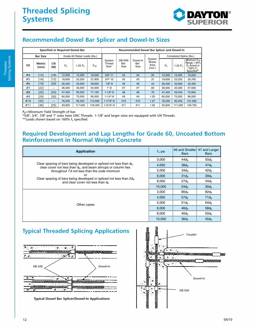
Recommended Dowel Bar Splicer and Dowel-In Sizes
Required Development and Lap Lengths for Grade 60, Uncoated Bottom Reinforcement in Normal Weight Concrete
Typical Threaded Splicing Applications
Py=Minimum Yield Strength of bar. *5/8", 3/4", 7/8" and 1" sizes have UNC Threads. 1-1/8" and larger sizes are equipped with UN Threads.**Loads shown based on 160% fy specified.
Typical Dowel Bar Splicer/Dowel-In Applications
Dowel-InDB-SAE
Dowel-In
DB-SAE
Coupler
Application f'c psi #6 and Smaller
Bars#7 and Larger
Bars
Other cases
6,000
5,000 34db 42db
4,000
3,000
38db
44db
47db
55db
8,000
10,000
3,000
4,000
5,000
8,000
6,000
31db
27db
24db
66db
57db
51db
40db
46db
39db
34db
30db
82db
71db
64db
50db
58db
10,000 36db 45db
Thre
aded
S
plic
ing
Sys
tem
s
Specified or Required Dowel Bar Recommended Dowel Bar Splicer and Dowel-In
Bar Size
US Metric (mm)
CN (M)
#4 [13] [10]#5 [16] [15]#6 [19] [20]#7 [22] —#8 [25] [25]#9 [29] [30]#10 [32] —#11 [36] [35]
Specified or Required Dowel Bar Recommended Dowel Bar Splicer and Dowel-In
#4 [#13]
BarSize
SystemThreadSize*
DB-SAEBar Size
Dowel-In Bar Size
SystemStressArea(min.)
#5 [#16]
#6 [#19]
#7 [#22]
#8 [#25]
#9 [#29]
#11 [#36]
#10 [#32]
12,000
18,600
26,400
36,000
47,400
60,000
93,600
76,200
15,000
23,250
33,000
45,000
59,250
75,000
117,000
95,250
18,000
27,900
39,600
54,000
71,100
90,000
140,400
114,000
5/8"-11
3/4"-10
7/8"-9
1"-8
1-1/8"-8
1-1/4"-8
1-9/16"-8
1-7/16"-8
#4
#5
#6
#7
#8
#9
#11
#10
#4
#5
#6
#7
#8
#9
#11
#10
.20
.31
.44
.60
.79
1.00
1.56
1.27
12,000
18,600
26,400
36,000
47,400
60,000
93,600
76,200
15,000
23,250
33,000
45,000
59,250
75,000
117,000
95,250
19,200
29,760
42,400
57,600
75,840
96,000
149,760
121,920
Py 1.25 Py Pult Py 1.25 Py
Minimum PultRange = 95%Fu Actual or
160% FySpecified**
Grade 60 Rebar Loads (lbs.) Completed Splice (lbs.)

1304/10
Threaded Splicing Systems
Dowel Bar Splicer SystemD-101 Dowel-in, D-102 90˚ Hooked Dowel-in, D-103 180˚ Hooked Dowel-in, D-104 Double-Ended Dowel-in
The Dayton Superior Dowel-In is available Straight (D-101), 90˚ and 180˚ Hooked (D-102 and D-103) and Double-Ended (D-104). Each is manufactured from grade 60 deformed rebar material and is available in rebar sizes #4 through #11 in plain or epoxy coated finish. The threaded end of the Dowel-In is enlarged by forging, before threading, to ensure that the cross-sectional area of the bar is not reduced by the threading operation. This design feature assures full ultimate strength of the rebar. Dowel-ins are configured to facilitate easy installation and can be easily assembled by hand. On larger proj-ects, such as highway paving, a centrifugal chuck on an electric or air-powered drill motor can be employed to speed installation. See the D-49 Magna Jaw on Page 55.
See D-108 HeadedDowel-In on page 17.
To Order:Specify: (1) quantity, (2) name, (3) bar size (should be equivalent to the rebar being substituted for on the structural drawings), (4) dimensions required (see below).
Example:600, D-102 90˚ Hooked Dowel-Ins, #5 rebar, A=14", B=8"
AA
C
R
R
B
A(+0–1/4")
D-102 90˚ Hooked Dowel-In
To order, give dimensions A, B and C as required
D-103 180˚ Hooked Dowel-In
D-104 Double-Ended Dowel-In
Bar SizeD-101 Dowel-In
Py=Minimum Yield Strength of bar. *5/8", 3/4", 7/8" and 1" sizes have UNC Threads. 1-1/8" and larger sizes are equipped with UN Threads.**Loads shown based on 160% fy specified.
ALap Splice Length or Development Length
Dia. +1/4"
Specified or Required Dowel Bar Recommended Dowel Bar Splicer and Dowel-In
Bar Size
USMet-ric
(mm)
CN (M)
#4 [13] [10]
#5 [16] [15]
#6 [19] [20]
#7 [22] —
#8 [25] [25]
#9 [29] [30]
#10 [32] —
#11 [36] [35]
Specified or Required Dowel Bar Recommended Dowel Bar Splicer and Dowel-In
#4 [#13]
BarSize
SystemThreadSize*
DB-SAEBar Size
Dowel-In Bar Size
SystemStressArea(min.)
#5 [#16]
#6 [#19]
#7 [#22]
#8 [#25]
#9 [#29]
#11 [#36]
#10 [#32]
12,000
18,600
26,400
36,000
47,400
60,000
93,600
76,200
15,000
23,250
33,000
45,000
59,250
75,000
117,000
95,250
18,000
27,900
39,600
54,000
71,100
90,000
140,400
114,000
5/8"-11
3/4"-10
7/8"-9
1"-8
1-1/8"-8
1-1/4"-8
1-9/16"-8
1-7/16"-8
#4
#5
#6
#7
#8
#9
#11
#10
#4
#5
#6
#7
#8
#9
#11
#10
.20
.31
.44
.60
.79
1.00
1.56
1.27
12,000
18,600
26,400
36,000
47,400
60,000
93,600
76,200
15,000
23,250
33,000
45,000
59,250
75,000
117,000
95,250
19,200
29,760
42,400
57,600
75,840
96,000
149,760
121,920
Py 1.25 Py Pult Py 1.25 Py
Minimum PultRange = 95%Fu Actual or
160% FySpecified**
Grade 60 Rebar Loads (lbs.) Completed Splice (lbs.)
* Tolerance on Bending Plus 0 / Minus 1" on "A" Dimension
NOTE: To be manufactured as Single End
Thre
aded
S
plic
ing
Sys
tem
s
Bar Size Designation D-101 Minimum MFG. Length DI
DOWEL INS
D-104 Minimum Length Double End Dowel Ins.
D-104 Minimum Length Double End Dowel Ins.US Metric
(mm)CN (M)
#4 [13] [10] 9" 4" * 8" **#5 [16] [15] 9" 5" * 8" **#6 [19] [20] 9 1/4" 6" * 8" **#7 [22] — 9 1/4" 7" * 8" **#8 [25] [25] 15 1/2" 8" * 14" **#9 [29] [30] 15 1/2" 9" * 14" **#10 [32] — 15 3/4" 10" * 14" **#11 [36] [35] 16" 11" * 14" **
** Plus thread each end.

14 04/10
Threaded Splicing Systems
Dowel Bar Splicer SystemD-101-A Straight Dowel Bar Splicer DB-SAE, D-102-A 90˚ Hooked Dowel Bar Splicer, D-103-A 180˚ Hooked Dowel Bar Splicer, D-104-A Double-Ended Dowel Bar Splicer
The Dayton Superior Dowel Bar Splicer is a one-piece unit, integrally forged from ASTM A615 grade 60 deformed rebar material. The splicers are available in #4 through #11 rebar sizes to be used in conjunction with the corresponding size dowel-in to accomplish a mechanical splice designed to achieve 160% of specified yield (full mechanical ultimate).
The splicer can be furnished straight (D-101-A) cut to length, 90˚ and 180˚ hooked (D-102-A and D-103-A) and double-ended (D-104-A) in plain or epoxy coated finish. The splicer can also be special-ordered with a reduced diameter washer flange or with the washer flange clipped (in more than one direction, if required) to provide adequate concrete cover, or to avoid interference.
The D-104-A Double-Ended Dowel Bar Splicer is used to establish a direct load path through a concrete section, thus avoiding multiple hooked rebar and eliminating rebar congestion. The double-ended unit can be configured in a “U” shape for special applications.
Clipped Flange
Nail Holes 1/2" Less
Than Flange O.D.
Optional Clipped Flange
D-101-A Dowel Bar Splicer
C Dia. D Dia.Min
A
Length As Specified
Rebar Size
Smooth Transition (Approx. 1/2" Fillet Radius)
.250 Typ.
E +0.125
-0.000
B±.063
Note: No. 4, 5 and 6 splicers, 18", 24" and 36" long will usually have a stamped metal plug to protect threads; all other sizes will have a plastic cap plug.
*Loads shown based on 160% fy specified
#4 [#13] 5/8"–11 UNC 1/8"
#5 [#16] 3/4"–10 UNC 1/8"
#6 [#19] 7/8"–9 UNC 1/8"
#7 [#22] 1"–8 UNC 1/8"
#8 [#25] 1-1/8"–8 UN 1/8"
#9 [#29] 1-1/4"–8 UN 1/8"
BarSize
ThreadSize
B
#10 [#32] 1-7/16"–8 UN 1/8"
#11 [#36] 1-9/16–8 UN 1/8"
1-1/8"
1-9/16"
1-11/16"
1-27/32"
2-1/16"
2-3/16"
A
2-7/16"
2-9/16"
11/16"
13/16"
15/16"
1-1/16"
1-3/16"
1-5/16"
C
1-1/2"
1-5/8"
55/64"
1-3/64"
1-15/64"
1-27/64"
1-19/32"
1-25/32"
D
2"
2-7/32"
1"
1-1/8"
1-1/4"
1-3/8"
1-1/2"
1-5/8"
E
1-13/16"
1-15/16"
1-7/8"
2-1/16"
2-1/4"
2-7/16"
2-5/8"
2-13/16"
FlangeDiameter
3"
3-1/4"
Minimum Pult Range = 95% Fu Actual or 160%
Fy Specified*
19,200 lbs.
29,760 lbs.
42,400 lbs.
57,600 lbs.
75,840 lbs.
96,000 lbs.
121,920 lbs.
149,760 lbs.
Flange Diameter ±1/8"
NOTE: To be manufactured as Single End
Thre
aded
S
plic
ing
Sys
tem
s
Bar Size Designation
US Metric (mm)
CN (M)
#4 [13] [10]
#5 [16] [15]
#6 [19] [20]
#7 [22] —
#8 [25] [25]
#9 [29] [30]
#10 [32] —
#11 [36] [35]
Bar Size Designation D-101-A Minimum MFG. Length DB-SAEUS Metric
(mm)CN (M)
#4 [13] [10] 12"
#5 [16] [15] 14"
#6 [19] [20] 16"
#7 [22] — 16"
#8 [25] [25] 16"
#9 [29] [30] 16"
#10 [32] — 16"
#11 [36] [35] 16"

1504/10
Threaded Splicing Systems
Dowel Bar Splicer System
To Order:Specify: (1) quantity, (2) name, (3) bar size (should be equivalent to the rebar being substituted for on the structural drawings), (4) dimensions required.
Example:600, D-101-A Dowel Bar Splicers, #5 rebar, 36" long.
A
R
B
A
R D
C
Overall Length(See chart below)
D-102-A 90˚ Hooked Dowel Bar Splicer
D-103-A 180˚ Hooked Dowel Bar Splicer
D-104-A Double-Ended Dowel Bar Splicer
Overall Length
D-101-A Dowel Bar Splicer
See D-108 Headed Dowel Bar Splicer on page 17.
Py=Minimum Yield Strength of bar. *5/8", 3/4", 7/8" and 1" sizes have UNC Threads. 1-1/8" and larger sizes are equipped with UN Threads.**Loads shown based on 160% fy specified.
Specified or Required Dowel Bar Recommended Dowel Bar Splicer and Dowel-In
Bar Size
USMet-ric
(mm)
CN (M)
#4 [13] [10]
#5 [16] [15]
#6 [19] [20]
#7 [22] —
#8 [25] [25]
#9 [29] [30]
#10 [32] —
#11 [36] [35]
Specified or Required Dowel Bar Recommended Dowel Bar Splicer and Dowel-In
#4 [#13]
BarSize
SystemThreadSize*
DB-SAEBar Size
Dowel-In Bar Size
SystemStressArea(min.)
#5 [#16]
#6 [#19]
#7 [#22]
#8 [#25]
#9 [#29]
#11 [#36]
#10 [#32]
12,000
18,600
26,400
36,000
47,400
60,000
93,600
76,200
15,000
23,250
33,000
45,000
59,250
75,000
117,000
95,250
18,000
27,900
39,600
54,000
71,100
90,000
140,400
114,000
5/8"-11
3/4"-10
7/8"-9
1"-8
1-1/8"-8
1-1/4"-8
1-9/16"-8
1-7/16"-8
#4
#5
#6
#7
#8
#9
#11
#10
#4
#5
#6
#7
#8
#9
#11
#10
.20
.31
.44
.60
.79
1.00
1.56
1.27
12,000
18,600
26,400
36,000
47,400
60,000
93,600
76,200
15,000
23,250
33,000
45,000
59,250
75,000
117,000
95,250
19,200
29,760
42,400
57,600
75,840
96,000
149,760
121,920
Py 1.25 Py Pult Py 1.25 Py
Minimum PultRange = 95%Fu Actual or
160% FySpecified**
Grade 60 Rebar Loads (lbs.) Completed Splice (lbs.)
** Based on barrels forged on each end. For lengths less than minimum - please check with Tremont - we may supply forged DB one end, DI with Coupler and nailer washer other end.
* Tolerance on Bending Plus 0 / Minus 1" on "A" Dimension
Thre
aded
S
plic
ing
Sys
tem
s
Bar Size Designation Bending DB or DI 90° only Minimum
"A" DimensionUS Metric (mm)
CN (M)
#4 [13] [10] 4" *
#5 [16] [15] 5" *
#6 [19] [20] 6" *
#7 [22] — 7" *
#8 [25] [25] 8" *
#9 [29] [30] 9" *
#10 [32] — 10" *
#11 [36] [35] 11" *
Bar Size Designation D-104-A Double-Ended Min.
Lengths
Tolerance Overall LengthUS Metric
(mm)CN (M)
#4 [13] [10] 12" O.A. +0 - 3/8"
#5 [16] [15] 12" O.A. +0 - 3/8"
#6 [19] [20] 14" O.A. +0 - 1/2"
#7 [22] — 16" O.A. +0 - 5/8"
#8 [25] [25] 16" O.A. +0 - 3/4"
#9 [29] [30] 16" O.A. +0 - 1"
#10 [32] — 16" O.A. +0 - 1"
#11 [36] [35] 16" O.A. +0 - 1"

16 04/10
Threaded Splicing Systems
Typical Dowel Bar Splicer System Installation
Formwork
Keyway
Splicer
1. Set forms, and nail or screw Splicer to form key.
Formwork
KeywayTied to Adjacent Reinforcing
2. Place required reinforcing steel.
1st PourDowel-In
3. After first pour has properly set, remove the formwork and screw Dowel-Ins into the exposed splicers.
Main Reinforcing Bar
Floor Slab Second Pour
Formwork
Lap Splice Length
4. Place second pour formwork and reinforcing steel.
1st Pour
Thre
aded
S
plic
ing
Sys
tem
s

1704/10
Head Thickness
Threaded Splicing Systems
Dowel Bar Splicer SystemD-108 Headed Dowel-In
The Dayton Superior D-108 Headed Dowel-In is a length of grade 60 deformed rebar with one end enlarged by forging and then threaded, and the other end forged into a bolt head configuration. The D-108 Headed Dowel-In is designed for use in congested areas where hooked dowel-ins cannot be utilized. D-108 Dowel-In is available in plain or epoxy coated finish. Standard length of D-108 is 12 times the bar diameter. Other lengths available on request.
D-108-A Headed Dowel Bar SplicerThe Dayton Superior D-108-A Headed Dowel Bar Splicer is designed to help ease
hooked rebar congestion. It has excellent anchorage capacities and can be used for common structural anchoring, such as one-sided forming, light standard support, signs, posts, etc. The D-108-A Splicers are available in sizes #4 through #11 in plain or epoxy coated finish. Standard lengths for D-108-A is 12 times the bar diameter. Other lengths available on request.
To Order:Specify: (1) quantity, (2) name, (3) bar size, (4) length.
Example:500, D-108 Headed Dowel-Ins, #6 rebar x 12" long.
Length
Chamfer
A
Thread Size Bar Size
Head Thickness
Length
E
AB
C Dia.
D-108-A Headed Dowel Bar Splicer
Thread Size
G Dia.
H Dia.
3 or 4 nail
holes at approx.
90˚
D-108 Headed Dowel-In
*Ultimate strength based on 160% fy specified.
*Ultimate strength based on 160% fy specified.
To Order:Specify: (1) quantity, (2) name, (3) bar size, (4) length.
Example:500, D-108-A Headed Dowel Bar Splicer, #5 rebar x 9" long.
Washer Dia.
Thre
aded
S
plic
ing
Sys
tem
s
** Plus Thread
Bar Size Designation D-108 Minimum Length Hex Head
Dowel InUS Metric (mm)
CN (M)
#4 [13] [10] 6" **
#5 [16] [15] 6" **
#6 [19] [20] 6" **
#7 [22] — 6" **
#8 [25] [25] 10" **
#9 [29] [30] 10" **
#10 [32] — 12" **
#11 [36] [35] 12" **
Bar Size DesignationD-108-A Minimum Length DB-SAE-3US Metric
(mm)CN (M)
#4 [13] [10] 5" O.A.
#5 [16] [15] 5" O.A.
#6 [19] [20] 6" O.A.
#7 [22] — 8" O.A.
#8 [25] [25] 8" O.A.
#9 [29] [30] 9" O.A.
#10 [32] — 12" O.A.
#11 [36] [35] 12" O.A.
5/8"–11 UNC 1/8"
3/4"–10 UNC 1/8"
7/8"–9 UNC 1/8"
1"–8 UNC 1/8"
1-1/8"–8 UN 1/8"
1-1/4"–8 UN 1/8"
BarSize
ThreadSize
B
1-7/16"–8 UN 1/8"
1-9/16–8 UN 1/8"
1-1/8"
1-9/16"
1-11/16"
1-27/32"
2-1/16"
2-3/16"
A
2-7/16"
2-9/16"
11/16"
13/16"
15/16"
1-1/16"
1-3/16"
1-5/16"
C
1-1/2"
1-5/8"
55/64"
1-3/64"
1-15/64"
1-27/64"
1-19/32"
1-25/32"
D
2"
2-7/32"
1"
1-1/8"
1-1/4"
1-3/8"
1-1/2"
1-5/8"
E
1-13/16"
1-15/16"
1-1/16"
1-5/16"
1-5/16"
1-3/8"
1-3/8"
1-3/4"
Width Across Flats
1-3/4"
2-1/16"
1-3/8"
1-5/8"
1-5/8"
1-7/8"
1-7/8"
2-1/8" – 2-1/4"
WasherDiameter
2-1/8" – 2-1/4"
2-1/2" – 2-5/8"
1/2"
1/2"
5/8"
5/8"
5/8"
3/4"
HeadThickness
3/4"
7/8"
18,000 lbs.
27,900 lbs.
39,600 lbs.
54,000 lbs.
71,100 lbs.
90,000 lbs.
UltimateStrength
114,300 lbs.
140,400 lbs.
#4 [#13]
#5 [#16]
#6 [#19]
#7 [#22]
#8 [#25]
#9 [#29]
#10 [#32]
#11 [#36]
Bar Size Designation
US Metric (mm)
CN (M)
#4 [13] [10]
#5 [16] [15]
#6 [19] [20]
#7 [22] —
#8 [25] [25]
#9 [29] [30]
#10 [32] —
#11 [36] [35]
5/8"–11 UNC
3/4"–10 UNC
7/8"–9 UNC
1"–8 UNC
1-1/8"–8 UN
1-1/4"–8 UN
BarSize
ThreadSize
1-7/16"–8 UN
1-9/16–8 UN
7/8"
1"
1-1/8"
1-1/4"
1-3/8"
1-1/2"
A
1-11/16"
1-13/16"
—
7/8"
1-1/16"
1-5/16"
1-5/16"
1-3/4"
Width Across Flats
1-3/4"
2-1/16"
—
1-3/16"
1-1/2"
1-3/4"
1-3/4"
2-1/8" – 2-1/4"
WasherDiameter
2-1/8" – 2-1/4"
2-1/2" – 2-5/8"
—
7/16"
7/16"
9/16"
9/16"
3/4"
HeadThickness
3/4"
7/8"
18,000 lbs.
27,900 lbs.
39,600 lbs.
54,000 lbs.
71,100 lbs.
90,000 lbs.
UltimateStrength
114,300 lbs.
140,400 lbs.
#4 [#13]
#5 [#16]
#6 [#19]
#7 [#22]
#8 [#25]
#9 [#29]
#10 [#32]
#11 [#36]
Bar Size Designation
US Metric (mm)
CN (M)
#4 [13] [10]
#5 [16] [15]
#6 [19] [20]
#7 [22] —
#8 [25] [25]
#9 [29] [30]
#10 [32] —
#11 [36] [35]

18 04/10
Threaded Splicing Systems
ICC ES Cyclic Test Averages for Dowel Bar Splicer SystemICC Evaluation Report No. 4028
Note: The above are average values derived from tests performed by Wiss, Janney, Elstner Associates, Inc. in accordance with ICC’s acceptance criteria AC-133. All bars met ICC’s Type 2 Splice Requirements.Note: One kip = 1,000 pounds.
0.31 -9.3
0.44 -13.2
0.60
0.79
1.00
0.20
-18.0
-23.7
-30.0
-6.0
BarSize
Cyclic Load Levels (Stages 1, 2, 3) Tensile Strength (Stage 4)Bar Area
sq. in. Pmin(kips)
17.7
25.1
34.2
45.0
57.0
11.4
Pmax1
(kips)
21.9
31.58
41.68
48.42
66.52
13.12
Pmax2
(kips)
30.23
45.01
60.24
79.64
95.66
20.08
(kips)
22.18
32.36
44.6
55.74
66.84
13.76
Pmax3
(kips)
97.5
102.3
100.42
100.84
95.66
100.42
ksi
162.4
170.4
167.4
168.0
159.2
167.2
%fy
#4 [#13]
#5 [#16]
#6 [#19]
#7 [#22]
#8 [#25]
#9 [#29]
Thre
aded
S
plic
ing
Sys
tem
s Bar Size
US Metric (mm)
CN (M)
#4 [13] [10]
#5 [16] [15]
#6 [19] [20]
#7 [22] —
#8 [25] [25]
#9 [2 9] [30]

1904/10
Threaded Splicing Systems
D-110 US/MC-SAE Coupler Splice System*ICC Evaluation Report No. 5216
The Dayton Superior D-110 US/MC-SAE Coupler Splice System is suitable for splicing reinforcement bars end to end. The mechanical connections accom-modate bar sizes #4 through #18 and are a convenient alterna-tive to lap splices and/or butt welding. Typical applications include splicing rebar in vertical column cages, mono-lithic structures, etc.
The standard cou-pler’s heavy wall design is manufactured from high quality steel and is tested in accordance with ACI, AASHTO and ASTM standards. The coupler is designed to achieve 160% of the specified yield (full mechanical ultimate) of the bar.
The D-110 coupler employs the attributes of the Dowel-In’s upset, upsized thread to achieve a strong, straight-line mechanical splice. Dowel-Ins or D-115 Inertia Splice Bars are threaded into the heavy duty coupler’s body to com-plete the splice. The D-110 coupler is also available with an optional washer face, if required.
A unique advantage of the D-110 US/MC-SAE Coupler is that the coupler can be advanced beyond the threaded region of the splice bar and then, after butting the two bars, can be back-threaded onto the second bar to com-plete the splice without having to turn the bars.
**Ultimate strength based on 160% fy specified.
Standard Coupler Splice
Length
2 Half Inch Arc Welds, 180˚ Apart
1/4"
Thread Size
Thickness
Specify Washer if required
To Order:Specify: (1) quantity, (2) name, (3) bar size.
Example:300, D-110 US/MC-SAE Couplers for #14 rebar.
Washer Diameter
D-110 US/MC-SAE Coupler Shown With Optional Washer Face
*U.S. Patent No. 5,152,118
4 Nail Holes Equally Spaced
Thre
aded
S
plic
ing
Sys
tem
s
D-110 US/MC-SAE Coupler Splice System
Product code w/out
Washer
Product Code with
Washer
Bar Size DesignationThread
SizeCouple
O.D. Coupler Length
Washer Diameter (Optional)
Coupler Ultimate
Strength**US Metric (mm)
CN (M)
123179 123187 #4 [13] [10] 5/8"-11 UNC 1" 2-1/4" 1-3/4" 19,200 lbs.
123180 123188 #5 [16] [15] 3/4"-10 UNC 1-1/8" 2-1/2" 2-1/4" 27,960 lbs.
111480 123189 #6 [19] [20] 7/8"-9 UNC 1-1/4" 2-3/4" 2-1/2" 42,240 lbs.
111490 123190 #7 [22] — 1"-8 UNC 1-1/2" 3" 2-1/2" 57,600 lbs.
111500 123191 #8 [25] [25] 1-1/8"-8 UN 1-5/8" 3-1/4" 2-3/4" 75,840 lbs.
111520 123192 #9 [29] [30] 1-1/4"-8 UN 1-7/8" 3-1/2" 3" 96,000 lbs.
111530 123193 #10 [32] — 1-7/16"-8 UN 2-1/4" 3-7/8" 3-1/2" 121,920 lbs.
111540 123194 #11 [36] [35] 1-9/16"-8 UN 2-3/8" 4-1/8" 3-3/4" 149,760 lbs.
111560 123195 #14 [43] [45] 1-7/8"-8 UN 2-3/4" 5-1/4" 4-1/4" 216,000 lbs.
111570 123196 #18 [57] [55] 2 1/2"-8 UN 3-5/8" 6-1/2" 5" 384,000 lbs.
20 04/10
Threaded Splicing Systems
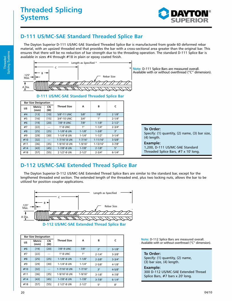
D-111 US/MC-SAE Standard Threaded Splice BarThe Dayton Superior D-111 US/MC-SAE Standard Threaded Splice Bar is manufactured from grade 60 deformed rebar
material, with an upsized threaded end that provides the bar with a cross-sectional area greater than the original bar. This ensures that there will be no reduction of bar strength due to the threading operation. The standard D-111 Splice Bar is available in sizes #4 through #18 in plain or epoxy coated finish.
D-112 US/MC-SAE Extended Thread Splice BarThe Dayton Superior D-112 US/MC-SAE Extended Thread Splice Bars are similar to the standard bar, except for the
lengthened threaded end section. The extended length of the threaded end, plus two locking nuts, allows the bar to be utilized for position coupler applications.
To Order:Specify: (1) quantity, (2) name, (3) bar size, (4) length.
Example:1,200, D-111 US/MC-SAE Standard Threaded Splice Bars, #7 x 10' long.
Length as Specified *
Rebar Size
C
B.125" Max.
A Dia.
D-111 US/MC-SAE Standard Threaded Splice Bar
D-112 US/MC-SAE Extended Thread Splice Bar
Length as Specified
Rebar Size
C
B.125" Max.
A Dia.
To Order:Specify: (1) quantity, (2) name, (3) bar size, (4) length.
Example:300 D-112 US/MC-SAE Extended Thread Splice Bars, #7 bars x 20' long.
* Note: D-111 Splice Bars are measured overall. Available with or without overthread (“C” dimension).
Note: D-112 Splice Bars are measured overall. Available with or without overthread (“C” dimension).
Thre
aded
S
plic
ing
Sys
tem
s
Bar Size DesignationThread Size A B C
US Metric (mm)
CN (M)
#4 [13] [10] 5/8"-11 UNC 5/8" 7/8" 2 1/8"
#5 [16] [15] 3/4"-10 UNC 3/4" 1" 2-1/4"
#6 [19] [20] 7/8"-9 UNC 7/8" 1-1/8" 2-1/2"
#7 [22] — 1"-8 UNC 1" 1-1/4" 2-3/4"
#8 [25] [25] 1-1/8"-8 UN 1-1/8" 1-3/8" 3"
#9 [29] [30] 1-1/4"-8 UN 1-1/4" 1-1/2" 3-1/4"
#10 [32] — 1-7/16"-8 UN 1-7/16" 1-11/16" 3-5/8"
#11 [36] [35] 1-9/16"-8 UN 1-9/16" 1-13/16" 3-7/8"
#14 [43] [45] 1-7/8"-8 UN 1-7/8" 2-1/8" 5"
#18 [57] [55] 2 1/2"-8 UN 2-1/2" 2-3/4" 6-1/4"
Bar Size DesignationThread Size A B C
US Metric (mm)
CN (M)
#6 [19] [20] 7/8"-9 UNC 7/8" 2" 3-1/8"
#7 [22] — 1"-8 UNC 1" 2-1/4" 3-3/8"
#8 [25] [25] 1-1/8"-8 UN 1-1/8" 2-3/8" 3-3/4"
#9 [29] [30] 1-1/4"-8 UN 1-1/4" 2-5/8" 4-1/8"
#10 [32] — 1-7/16"-8 UN 1-7/16" 3" 4-5/8"
#11 [36] [35] 1-9/16"-8 UN 1-9/16" 3-1/8" 4-7/8"
#14 [43] [45] 1-7/8"-8 UN 1-7/8" 3-7/8" 6-1/4"
#18 [57] [55] 2 1/2"-8 UN 2-1/2" 5" 8"

2104/10
Threaded Splicing Systems
D-105 US/MC-SAE Transition CouplerThe Dayton Superior D-105 US/MC-SAE Transition Coupler is used to provide a mechanical connection of two threaded
rebar of different diameters. The D-105 coupler is designed to achieve 160% fy of the smaller bar. See the chart for standard sizes. The D-105 coupler can be furnished with or without a mounting washer and can be special-ordered in other than standard sizes.
Length
.250 Thread Size B
Thread Size A
Class 2B Thread
OD
D-105 US/MC-SAETransition Coupler
To Order:Specify: (1) quantity, (2) name, (3) rebar sizes, (4) flange information.
Example:250, D-105 US/MC SAE Transition Couplers, #6 to #7 rebar without mounting flanges.
Typical Splice
Optional Mounting Washer
1/2" Weld Typ. 2 Plcs.
** Ultimate strength based on 160% fy specified.
Rebar SizeSize Thread Size Coupler Coupler
Ultimate Strength**US Metric
(mm) CN (M) A B O.D. Length
#4-#5 [13-16] [10-15] 5/8"-11 UNC 3/4"-10 UNC 1-1/8" 2-5/8" 19,200 lbs.
#5-#6 [16-19] [15-20] 3/4"-10 UNC 7/8"-9 UNC 1-1/4" 2-7/8" 29,760 lbs.
#6-#7 [19-22] — 7/8"-9 UNC 1"-8 UNC 1-1/2" 3-1/8" 42,240 lbs.
#7-#8 [22-25] — 1"-8 UNC 1-1/8"-8 UN 1-5/8" 3-3/8" 57,600 lbs.
#7-#9 [22-29] — 1"-8 UNC 1-1/4"-8 UNC 1-7/8" 3-1/2" 57,600 lbs.
#8-#9 [25-29] [25-30] 1-1/8"-8 UN 1-1/4"-8 UN 1-7/8" 3-5/8" 75,840 lbs.
#8-#10 [25-32] — 1-1/8"-8 UN 1-7/16"-8 UN 2-1/4" 3-7/8" 75,840 lbs.
#9-#10 [29-32] — 1-1/4"-8 UN 1-7/16"-8 UN 2-1/4" 4" 96,000 lbs.
#9-#11 [29-36] [30-35] 1-1/4"-8 UN 1-9/16"-8 UN 2-3/8" 4-1/8" 96,000 lbs.
#10-#11 [32-36] — 1-7/16"-8 UN 1-9/16"-8 UN 2-3/8" 4-1/4" 121,920 lbs.
#10-#14 [32-43] — 1-7/16"-8 UN 1-7/8"-8 UN 2-3/4" 4-5/8" 121,920 lbs.
#11-#14 [36-43] [35-45] 1-9/16"-8 UN 1-7/8"-8 UN 2-3/4" 4-3/4" 149,760 lbs.
#11-#18 [36-57] [35-55] 1-9/16"-8 UN 2-1/2"-8 UN 3-5/8" 5-3/8" 149,760 lbs.
#14-#18 [43-57] [45-55] 1-7/8"-8 UN 2 1/2"-8 UN 3-5/8" 5-5/8" 216,000 lbs.
D-105 US/MC-SAE Transition Coupler
Thre
aded
S
plic
ing
Sys
tem
s

22 04/10
Threaded Splicing Systems
Length
Chamfer Size
Thread Size
.250
20˚
D-106 US/MC-SAE Welding Half CouplerThe Dayton Superior D-106 US/MC-SAE Welding Half Coupler provides a method of connecting rebar to structural steel
members, such as piles, weld plates, beams, columns, etc. The D-106 coupler is fabricated from steel meeting ASTM A108 grade 1018 or 1020 and is designed to allow maximum weld capacity. Successful welds can be produced at the job site, providing that good welding practices are maintained.
To Order:Specify: (1) quantity, (2) name, (3) rebar size.
Example:150, D-106 US/MC-SAE Welding Half Couplers for #8 rebar.
Weld
See Weld Detail
Steel Plate
D-106 US/MC-SAEWelding Half
Coupler
Note: Designed to be used with single bevel groove weld (types) SMAW, GMAW or FCAW. Reference American Welding Society Standard, ANSI/ASW D1.1
Steel Plate
Weld Detail
Single Bevel Groove Weld per AWS Standards
D-106 US/MC-SAE Welding Half Coupler
** Actual ultimate strength depends on the strength of the field weld and the material to which the coupler is welded. Ultimate strength based on 160% fy specified
Product Code
Bar Size Designation Thread Size
Coupler O.D.
Coupler Length
Chamfer Size
Coupler Ultimate
Strength**US Metric (mm)
CN (M)
77714 #4 [13] [10] 5/8" -11 UNC 1 -1/4" 1-1/8" 1/4" 19,200 lbs.
77715 #5 [16] [15] 3/4" -10 UNC 1 -1/4" 1-1/4" 1/4" 29,760 lbs.
77716 #6 [19] [20] 7/8" -9 UNC 1 -1/4" 1-3/8" 3/8" 42,240 lbs.
77717 #7 [22] — 1"-8 UNC 1-1/2" 1-1/2" 3/8" 57,600 lbs.
77718 #8 [25] [25] 1-1/8"-8 UN 1-5/8" 1-5/8" 1/2" 75,840 lbs.
77719 #9 [29] [30] 1-1/4"-8 UN 1-7/8" 1-3/4" 9/16" 96,000 lbs.
77720 #10 [32] — 1-7/16"-8 UN 2-1/4" 1-15/16" 5/8" 121,920 lbs.
77721 #11 [36] [35] 1-9/16"-8 UN 2-3/8" 2-1/16" 3/4" 149,760 lbs.
#14 [43] [45] 1-7/8"-8 UN 2-3/4" 2-3/8" 15/16" 216,000 lbs.
#18 [57] [55] 2 1/2"-8 UN 3-5/8" 3" 1-1/8" 384,000 lbs.
Thre
aded
S
plic
ing
Sys
tem
s

2304/10
Threaded Splicing Systems
D-106-S US/MC-SAE Welding StudThe Dayton Superior D-106-S US/MC-SAE Welding Stud is available to provide an alternate method of connecting rebar
to structural steel members. The D-106-S Welding Stud is fabricated from ASTM A108 grade 1035 steel.
D-106-S US/MC-SAEWelding Stud D-111 Threaded Splice Bar
With Over-Thread
D-110 Coupler
Butt D-111 Splice Bar/D-110 US/MC-SAE Coupler Assembly to the welding stud and thread the coupler onto the stud.
Connection completeNote: Designed to be used with multiple bevel groove weld (types) SMAW, GMAW or FCAW. Reference American Welding Society Standard, ANSI/ASW D1.1
Note: The application shown allows the connection to be made without turning the rebar.
*Actual ultimate strength depends on the strength of the field weld and the material to which the cou-pler is welded. Ultimate Strengths shown are based on 160% fy specified.
To Order:Specify: (1) quantity, (2) name, (3) rebar sizes.
Example:200, D-106-S US/MC-SAE Welding Stud, #8 rebar.
See D-111 US/MC-SAE Standard Threaded Splice Bar on page 20.
Bar Size DesignationThread Size Length
(in.)Chamfer Size
(in.)Stud Ultimate
Strength*US Metric (mm)
CN (M)
#4 [13] [10]
#5 [16] [15]
#6 [19] [20]
#7 [22] —
#8 [25] [25]
#9 [29] [30]
#10 [32] —
#11 [36] [35]
#14 [43] [45]
#18 [57] [55]
WeldingStud Size
ThreadSize
5/8"–11 UNC
3/4"–10 UNC
7/8"–9 UNC
1"–8 UNC
1-1/8"–8 UN
1-1/4"–8 UN
1-7/16"–8 UN
1-9/16"–8 UN
1-7/8"–8 UN
2-1/2"–8 UN
19,200 lbs.
29,760 lbs.
42,240 lbs.
57,600 lbs.
75,890 lbs.
96,000 lbs.
121,920 lbs.
149,760 lbs.
216,000 lbs.
384,000 lbs.
1-1/2"
1-5/8"
1-7/8"
2"
2-1/4"
2-1/2"
Length(In.)
2-3/4"
3"
3-3/8"
4-1/4"
1/4"
1/4"
3/8"
3/8"
1/2"
9/16"
ChamferSize (In.)
5/8"
3/4"
7/8"
1-1/8"
Stud Ultimate Strength*
#4 [#13]
#5 [#16]
#6 [#19]
#7 [#22]
#8 [#25]
#9 [#29]
#10 [#32]
#11 [#36]
#14 [#43]
#18 [#57]
Thre
aded
S
plic
ing
Sys
tem
s

24 04/10
Threaded Splicing Systems
D-107 US/MC-SAE Position CouplerThe Dayton Superior D-107 US/MC-SAE Position Coupler provides
a means to splice reinforcing steel without having to turn the rebar. In places with little working space or heavy rebar congestion, the D-107 coupler offers an efficient splicing alternative. D-107 couplers are available for standard splices (bars of equal size) and transition splices (bars of unequal sizes).
To ensure adequate thread length, the D-107 Position Coupler requires the D-112 Extended Thread Splice Bar on page 20.
Lock nut and coupler are threaded completely onto one bar. Thread lock nut onto second bar.
Butt the bars together and reverse thread coupler onto second bar. Thread lock nuts to coupler and tighten nuts.
D-112 D-112Coupler
LengthLength as required
Lock NutLock Nut
Coupler
Lock Nut
Lock Nut
D-107 US/MC-SAEPosition Coupler
To Order:Specify (1) quantity, (2) name, (3) bar size(s).
Example:500, D-107 US/MC-SAE Position Couplers for #6 rebar.
*Ultimate Strength based on 160% fy specified.
D-107 US/MC-SAE Position Coupler DimensionsBar Size Designation Thread
SizeCoupler
O.D. Coupler Length
Locknut Length
Coupler Ultimate
Strength**US Metric
(mm)CN (M)
#4 [13] [10] 5/8"-11 UNC 1" 2-1/4" 13/32" 19,200 lbs.#5 [16] [15] 3/4"-10 UNC 1-1/8" 2-1/2" 1/2" 27,960 lbs.#6 [19] [20] 7/8"-9 UNC 1-1/4" 2-3/4" 19/32" 42,240 lbs.#7 [22] — 1"-8 UNC 1-1/2" 3" 11/16" 57,600 lbs.#8 [25] [25] 1-1/8"-8 UN 1-5/8" 3-1/4" 3/4" 75,840 lbs.#9 [29] [30] 1-1/4"-8 UN 1-7/8" 3-1/2" 27/32" 96,000 lbs.
#10 [32] — 1-7/16"-8 UN 2-1/4" 3-7/8" 31/32" 121,920 lbs.#11 [36] [35] 1-9/16"-8 UN 2-3/8" 4-1/8" 1-1/16" 149,760 lbs.#14 [43] [45] 1-7/8"-8 UN 2-3/4" 5-1/4" 1-1/4" 216,000 lbs.#18 [57] [55] 2 1/2"-8 UN 3-5/8" 6-1/2" 1-11/16" 384,000 lbs.
Thre
aded
S
plic
ing
Sys
tem
s

2504/10
Bar Size DesignationBar Area (sq. in.)
Cyclic Load Levels (Stages 1,2,3) Tensile Strength (Stage 4)
US Metric (mm)
CN (M)
Pmin (kips)
Pmax1 (kips)
Pmax2 (kips)
Pmax3 (kips) (kips) (ksi) %fy
#4 [13] [10] 0.20 -6.0 11.4 12.14 12.92 19.79 99.00 164.8%
#5 [16] [15] 0.31 -9.3 17.7 21.68 21.62 30.17 97.32 162.2%
#6 [19] [20] 0.44 -13.2 25.1 26.20 27.28 42.83 97.34 162.8%
#7 [22] — 0.60 -18.0 34.2 42.08 43.88 60.64 100.94 168.2%
#8 [25] [25] 0.79 -23.7 45.0 48.58 53.12 79.42 100.54 167.4%
#9 [29] [30] 1.00 -30.0 57.0 65.54 69.84 95.20 95.54 159.2%
#10 [32] — 1.27 -38.1 72.4 80.00 83.64 124.54 98.06 163.4%
#11 [36] [35] 1.56 -46.8 88.9 102.96 103.00 149.02 95.52 159.2%
#14 [43] [45] 2.25 -67.5 128.3 143.42 158.78 220.24 97.88 163.2%
#18 [57] [55] 4.00 -120.0 228.0 259.3 287.2 395.3 98.7 165%
Threaded Splicing Systems
ICC ES Cyclic Test Averages on Dayton Superior US/MC SplicesICC Evaluation Report No. 5216
The above are average values derived from tests performed by Wiss, Janney, Elstner Associates, Inc. in accordance with ICC’s acceptance criteria AC-133. All bars met ICC’s Type 2 Splice Requirements.Note: One kip = 1,000 pounds.
Thre
aded
S
plic
ing
Sys
tem
s

26 04/10
Threaded Splicing Systems
D-50 DBR Coupler SystemThe DBR Couplers and DBR Setting/Splice Bars are simple, easy
to use and familiar to all construction workers. The coupler is fas-tened to the formwork by nails, screws or a NC threaded bolt of proper diameter and length. The D-50 DBR Coupler splice meets or exceeds codes requiring 125% fy.
D-50 DBR Coupler and DBR Setting/Splice BarsThe Dayton Superior D-50 DBR Coupler is fabricated from high quality steel
satisfying ASTM A-108 and is tested in accordance with ACI, AASHTO and ASTM standards. DBR Couplers accommodate rebar sizes #4 through #11 and have an internal positive stop to ensure proper thread engagement. Refer to tables for additional specifications.
D-50 DBR Coupler
D-51 Setting-Splice Bar
To Order:Specify: (1) quantity, (2) name, (3) rebar size
Example:500 pcs., D-50 DBR Coupers, #8 rebar.
Approx. 1/8"
2" x 2" washer for DBR Bar Size #4 through #9, 3" x 3" washer for DBR Bar Size #10 and 11.
D-50 DBR Coupler
O.D.
Length
Positive Stop
Product Code
Bar Size DesignationThread Data O.D. x Length
US Metric (mm)
CN (M)
77098 #4 [13] [10] 1/2" -13 UNC 3/4" x 1- 7/8"
77100 #5 [16] [15] 5/8" - 11 UNC 7/8" x 2"
77110 #6 [19] [20] 3/4" -10 UNC 1- 1/16" x 2- 3/8"
77120 #7 [22] — 7/8" - 9 UNC 1- 1/4" x 2- 3/4"
77130 #8 [25] [25] 1" - 8 UNC 1- 3/8" x 3- 1/8"
77140 #9 [29] [30] 1 1/8" - 8 UN 1- 5/8" x 3- 5/8"
77142 #10 [32] — 1 1/4" - 8 UN 1- 3/4" x 4- 1/8"
77144 #11 [36] [35] 1 3/8" - 8 UN 1-15/16" x 4- 3/8"
Note: Threads on #9, #10 and #11 couplers are UN not NC.
Thre
aded
S
plic
ing
Sys
tem
s
D-50 DBR Coupler Selection Chart

2704/10
Threaded Splicing Systems
D-51 DBR Straight Bar Threaded One End
D-54 DBR Straight Bar Threaded Both Ends
D-52 DBR 90˚ Hook Bar and D-53 180˚ Hook Bar Threaded One End
Note: Color coded removable plastic caps available on request.D-51 overall length is required length less one half of coupler length.D-54 overall length is required length less coupler length minus 5/16".
Overall Length
DBR Rebar Size
To Order:Specify: (1) quantity, (2) name, (3) bar size (4) dimension “B” (as specified on plans) (5) dimension “C” or “D” and (6) dimension “R”
Example:500 pcs., D-52 90˚ Hook Bar, #6, B=7", C=20", R=2"
Notes: Color coded removable plastic caps available on request.*Based on “R” minimum as shown. Standard dimensions are to CRSI standard by pin size.
Thread Engagement
A
C
RRDBR Rebar
Size
D-53 180˚ Hook BarD-52 90˚ Hook Bar
B
A
DBR Rebar Size
Overall Length (Round to next even inch)
Lap Splice Length or Development Length
Thread Engagement
Thread Engagement
Thread Engagement
B
Thre
aded
S
plic
ing
Sys
tem
s
Bar Size DesignationThread Data A Thread
EngagementUS Metric (mm)
CN (M)
#4 [13] [10] 1/2"-13 UNC 3/4"#5 [16] [15] 5/8"-11 UNC 7/8"#6 [19] [20] 3/4"-10 UNC 1-1/16"#7 [22] — 7/8"- 9 UNC 1-1/4"#8 [25] [25] 1"- 8 UNC 1-7/16"#9 [29] [30] 1-1/8"- 8 UN 1-11/16"#10 [32] — 1-1/4"- 8 UN 1-15/16"#11 [36] [35] 1-3/8"- 8 UN 2-1/16"
Bar Size Designation Thread
Data
Thread Engage-
ment
B* Standard
For D-52
B Standard
For D-53
D Standard
For D-53
RStandard
US Metric (mm)
CN (M)
#4 [13] [10] 1/2"-13 UNC 3/4" 4-1/2" 9-3/4" 4-1/2" 1-1/2"
#5 [16] [15] 5/8"-11 UNC 7/8" 5-1/2" 12" 5" 1-7/8"
#6 [19] [20] 3/4"-10 UNC 1-1/16" 7" 23" 6" 2-1/4"
#7 [22] — 7/8"- 9 UNC 1-1/4" 8" 24" 7" 2-5/8"
#8 [25] [25] 1"- 8 UNC 1-7/16" 9" 25" 8" 3"
#9 [29] [30] 1-1/8"- 8 UN 1-11/16" 11" 31" 10-3/8" 4-3/4"
#10 [32] — 1-1/4"- 8 UN 1-15/16" 12" 32" 11-5/8" 5-3/8"
#11 [36] [35] 1-3/8"- 8 UN 2-1/16" 14" 33" 12-7/8" 6"
D-51 Straight Bar Selection Chart
D-52 and D-53 Hook Bar Selection Chart

28 04/10
Threaded Splicing Systems
How to Install the DBR Coupler System
After the formwork is stripped, a second DBR Setting/Splice Bar is threaded into the exposed end of the D-50 coupler until the stop is reached.
Formwork
Keyway
Keyway
Formwork
Tied to Adjacent Reinforcing
Floor Slab Second Pour
DBR Setting/ Splice Bar
Main Reinforcing Bar
D-50, DBR Coupler
DBR Setting/ Splice Bar
1st Pour
Step 1 Step 2
Step 3
Lap Splice Length
DBR Setting/ Splice Bar1st Pour
The DBR Setting/Splice Bar is tied off to adjacent reinforcing steel, for proper support during concrete placement as well as to maintain the required lap splice length.
A DBR Setting/Splice Bar is threaded into the D-50 cou-pler until the positive thread stop is reached. The D-50 DBR coupler is then fastened to the formwork with nails, screws or bolts.
The DBR Setting/Splice bar is tied to the adjacent reinforcing steel maintaining the proper lap splice length. The dowel bar replacement is now complete, ready for final concrete placement.
Step 4
Thre
aded
S
plic
ing
Sys
tem
s
D-52 and D-53 Hook Bar Selection Chart
1/2"-13 NC 0.14190.20
MinimumYield (lbs.)
Reinforcing Bar
Area (in2)
Reinforcing Bar
Size Designation
ThreadData
Thread TensileStress Area (in2)
12,000
5/8"-11 NC 0.2260.31 18,600
3/4"-10 NC 0.3340.44 26,400
7/8"-9 NC 0.4620.60 36,000
1"-8 UNC 0.6060.79 47,400
1-1/8"-8 UN 0.7901.00 60,000
15,000
125% fy MinimumRequirement (lbs.)
23,250
33,000
45,000
59,250
75,000
1-1/4"-8 UN 1.0001.27 76,200
1-3/8"-8 UN 1.2331.56 93,600
MinimumUltimate
(lbs.)
18,000
27,900
39,600
54,000
71,100
90,000
114,300
140,400
95,250
117,000
105,708
MinimumUltimate Tensile
Stress (psi)
102,876
98,802
97,403
97,772
94,937
95,250
94,891
1-5/8"-8 UN 1.7802.25 135,000 202,500 168,750 94,803
ASTM A-615 Grade 60 Reinforcing Bar Data
Thread Data
#4 [#13]
#5 [#16]
#6 [#19]
#7 [#22]
#8 [#25]
#9 [#29]
#10 [#32]
#11 [#36]
#14 [#43]
Bar Size Designation
US Metric (mm)
CN (M)
#4 [13] [10]
#5 [16] [15]
#6 [19] [20]
#7 [22] —
#8 [25] [25]
#9 [29] [30]
#10 [32] —
#11 [36] [35]
#14 [43] [45]

2904/10
Taper-Lock®
Why Taper-Lock is BetteruICC Evaluation Report ESR-2481 uPortable design allows you to take the system wherever
you need it.
uSharpen cutters up to three times for previously unheard of efficiency! Spend less money on new blades, and save your crew from unnecessary downtime.
uRevolutionary high-speed taper cut more than doubles the production of conventional cutters, allowing you to beat deadlines and reduce costs.
uNo need to purchase any costly additional cutting fluids — simply use a conventional water-soluble cutting fluid.
uStrong unit withstands tough projects. Straightforward process makes operation and repair easy.
Splice Rebar On-site, in a Fraction of the TimeYou already rely on Bar-Lock® couplers from Dayton Superior — the company you trust is proud to offer the portable, high-speed taper cut solution! Turn the system that’s already been proven on sites throughout Europe into your on-site advantage. Dayton Superior is the only company able to bring the reliable Taper-Lock design to North American fabrictors and contractors.
Use the Dayton Taper-Lock on Your Next Job SiteThe compact design saves room in your fabrication shop or on the job with all the advantages and one-quarter the size of similar machines, it’s time to re-think rebar splicing! Strength certification and test results are available upon request through the qualified Dayton Superior Dealer network throughout North America.
Tape
r-Lo
ck®
TYPICAL SPECIFICATIONS:Specific:Mechanical connections shall be Taper-Lock® taper threaded couplers as manufactured by Dayton Superior Corp.
Generic:The mechanical connection shall meet building code requirements of developing in tension and compression as required by__________ (insert name here). The mechanical connection shall be the positive locking, taper threaded type coupler manufactured from high quality steel. The bar ends must be taper threaded using the manufacturer’s bar threading equipment to ensure proper taper and thread engagement. All couplers shall be installed per the manufac-turer’s approved procedures.

30 04/10
Taper-Lock®
Bar Size Made in the USA (Black)
ASTM A311Grade 1144
Made in the USA(Epoxy)
ASTM A311Grade 1144
Made in the USA(Hot dipped Galvanized)
ASTM A311 Grade 1144
(Black)ASTM A576Grade 1045
(Epoxy)ASTM A576Grade 1045US Metric
(mm)CN (m)
#4 [13] [10] 127020 127258 128037 126389 128322 #5 [16] [15] 127021 127259 128038 126390 128323 #6 [19] [20] 127022 127260 128039 126391 128324 #7 [22] - 127023 127261 128040 126392 128325 #8 [25] [25] 127024 127262 128041 126393 128326 #9 [29] [30] 127025 127263 120842 126394 128327 #10 [32] - 127026 127264 128043 126395 128328 #11 [36] [35] 127027 127265 128044 126396 128329 #14 [43] [45] 127028 127266 128045 126397 128330 #18 [57] [55] 127019 127267 128046 126398 128331
Bar Size “A” “B” (Nominal)
US Metric (MM)
CN (M) US (mm) US (mm)
#4 [13] [10] 2.362 [60] 1.024 [26]
#5 [16] [15] 2.756 [70] 1.221 [31]
#6 [19] [20] 2.874 [73] 1.281 [32.5]
#7 [22] − 3.189 [81] 1.399 [35.5]
#8 [25] [25] 3.622 [92] 1.615 [41]
#9 [29] [30] 4.016 [102] 1.812 [46]
#10 [32] − 4.488 [114] 2.049 [52]
#11 [36] [35] 4.921 [125] 2.246 [57.5]
#14 [43] [45] 5.827 [148] 2.719 [69]
#18 [57] [55] 7.638 [194] 3.625 [92]
D-310 TAPER-LOCK STANDARD COUPLERPRODUCT DESCRIPTION:The D-310 Taper-Lock is used to join any bar-to-bar connection of the same size, where one bar can be rotated. This simplifies rebar splicing in areas where rebar congestion prevents the use of long lap splices. Engagement of the bar within the coupler is simplified by the taper thread which aids in alignment.
PRODUCT FEATURES AND BENEFITS:• Used in 80% of all connections• The compact design of the coupler ensures suitability for use in confined situations where space is restricted or where the loss of cover must be minimized
• Reduces engineering design time• Eliminates rebar congestion• Provides Type 2 splicing capacities (160% Fy) and simplifies
load paths• Meets approval from ICC (ESR 2481), ACI, CalTrans,
IBC2006, and Ministries of Transportation for Ontario and Quebec
• Approved for use in fatigue applications
PRODUCT SPECIFICATIONS:• Extension of Taper-Lock product line• Accommodates rebar sizes #4 through #18• Available in Black, Epoxy or Hot-Dipped Galvanized• Type 2 Splice (160% of Fy)• Connect bars of the same size using an internal sleeve with
two right hand tapered threads• Each end must be tightened with calibrated torque wrench
PRODUCT CODES
NOMINAL ENGAGEMENT
A
B
Tape
r-Lo
ck®
HOW TO ORDER:SPECIFY:1. Quantity2. Name3. Rebar size4. Finish5. Made in USA requirement
EXAMPLE:1. 500 pieces2. D-310 Taper-Lock® Standard Coupler3. #64. Black5. Made in the USA not required

3104/10
Tape
r-Lo
ck®
INSTALLATION:D-310 TAPER-LOCK STANDARD COUPLER
STEP 1The coupler is nor-mally supplied fixed to the reinforcing bar, ready to be installed and cast in concrete.
STEP 2After casting the con-crete and when ready to extend, remove the thread protector from the coupler. Position the continuation bar in the sleeve and rotate the bar into the coupler.
STEP 3Continue to screw the bar into the coupler until tight.
STEP 4To ensure correct installation, tighten the joint to the specified torque using the cali-brated torque wrench on the continuation bar.
Taper-Lock®
Rebar Size Applied Torque Wrench Setting
Imperial Metric (mm)
CN (M)
Imperial Metric Large Small
Imperial Metric Imperial Metric
#4 13mm [10] 55 lb-ft 75 Nm - - 39 lb-ft 53 Nm
#5 16mm [15] 81 lb-ft 110 Nm 62 lb-ft 84 Nm 57 lb-ft 77 Nm
#6 19mm [20] 111 lb-ft 150 Nm 85 lb-ft 115 Nm 78 lb-ft 106 Nm
#7 22mm — 151 lb-ft 205 Nm 116 lb-ft 157 Nm 105 lb-ft 143 Nm
#8 25mm [25] 199 lb-ft 270 Nm 153 lb-ft 207 Nm 139 lb-ft 188 Nm
#9 29mm [30] 207 lb-ft 280 Nm 159 lb-ft 215 Nm 146 lb-ft 198 Nm
#10 32mm — 210 lb-ft 285 Nm 162 lb-ft 219 Nm 147 lb-ft 199 Nm
#11 36mm [35] 225 lb-ft 305 Nm 173 lb-ft 234 Nm - -
#14 43mm [45] 247 lb-ft 335 Nm 190 lb-ft 257 Nm - -
#18 57mm [55] 247 lb-ft 335 Nm 190 lb-ft 257 Nm - -
TORQUE SETTINGS: D-310 TAPER-LOCK STANDARD COUPLER
Taper-Lock Coupler Torque Chart

32 04/10
Taper-Lock®Ta
per-
Lock
®
D-320 TAPER-LOCK TRANSITIONAL COUPLER
Bar Size Made in the USA (Epoxy)ASTM A311Grade 1144
Made in the USA (Black)ASTM A311Grade 1144US Metric
(mm)CN (m)
#4-#5 [13-16] [10-15] 127249 127218#5-#6 [16-19] [15-20] 127250 127219#6-#7 [19-22] - 127251 127220#7-#8 [22-25] - 127252 127221#8-#9 [25-29] [25-30] 127253 127222#9-#10 [29-32] 127254 127223#10-#11 [32-36] - 127255 127224#11-#14 [36-43] [35-45] 127256 127225#14-#18 [43-57] [45-55] 127257 127226
HOW TO ORDER :SPECIFY:1. Quantity2. Name3. Rebar size4. Finish
EXAMPLE:1. 500 pieces2. D-320 Taper-Lock® Transitional Coupler3. #6 - #74. Black
PRODUCT CODES
Other sizes available upon request
Bar Size “A” “B” (Nominal) “C” (Nominal)US Metric
[mm]CN [M] US [mm] US [mm] US [mm]
#4-#5 [13-16] [10-15] 2.7953 [71] 1.5748 [40] 1.0236 [26]
#5-#6 [16-19] [15-20] 3.0315 [77] 1.6535 [42] 1.378 [35]
#6-#7 [19-22] — 3.2283 [82] 1.7931 [45.5] 1.437 [36.5]
#7-#8 [22-25] — 3.6024 [91.5] 2.0079 [51] 1.5945 [40.5]
#8-#9 [25-29] [25-30] 4.0157 [102] 2.2047 [56] 1.811 [46]
#9-#10 [29-32] — 4.4488 [113] 2.4409 [62] 2.0079 [51]
#10-#11 [32-36] — 4.9213 [125] 2.6772 [68] 2.2441 [57]
#11-#14 [36-43] [35-45] 5.5906 [142] 3.1102 [79] 2.4803 [63]
#14-#18 [43-57] [45-55] 6.9291 [176] 4.0157 [102] 2.9134 [74]
NOMINAL ENGAGEMENT
A
B C
PRODUCT DESCRIPTION:The D-320 Taper-Lock is used to join two reinforcing bars of different sizes. It is commonly used for economic designs and columns where the diameter of the rebar reduces as the columns extend up the structure.
PRODUCT FEATURES AND BENEFITS:• Eliminates rebar congestion• Reduces engineering design time• Allows for the connection of two different size bars• Provides Type 2 splicing capacities (160% Fy) and simplifies load
paths• Meets approval from ICC (ESR 2481), ACI, CalTrans, IBC 2006
and Ministries of Transportation for Ontario and Quebec• Approved for use in fatigue applications
PRODUCT SPECIFICATIONS:• Extension of Taper-Lock product line• Accommodates all rebar configurations• Available in Black or Epoxy• Type 2 Splice (160% of Fy)• Threads in internal sleeve correspond to the appropriate bar size• Each end must be tightened and calibrated with a torque wrench

3304/10
INSTALLATION:D-320 TAPER-LOCK TRANSITIONAL COUPLER
TORQUE SETTINGS: D-320 TAPER-LOCK® TRANSITIONAL COUPLER
STEP 1The coupler is nor-mally supplied fixed to the reinforcing bar, ready to be installed and cast in concrete.
STEP 2After casting the con-crete and when ready to extend, remove the thread protector from the coupler. Position the continuation bar in the sleeve and rotate the bar into the coupler.
STEP 3Continue to screw the bar into the coupler until tight.
STEP 4To ensure correct installation, tighten the joint to the specified torque using the cali-brated torque wrench on the continuation bar.
Tape
r-Lo
ck®
Taper-Lock®
When installing the D-320 Transitional coupler, the larger of the two bars must be connected first the smaller bar is to be con-nected after the coupler is tightened to the appropriate torque on the larger rebar. This process ensures that the smaller bar does not receive the higher torque used to connect the larger bar. As an alternative, it is permitted to connect the smaller bar to the coupler first. If the smaller bar is connected first, a second wrench can be used to keep the coupler from rotating while the second connection to the larger bar is made.
Rebar Size Applied Torque Wrench Setting
Imperial Metric (mm)
CN (M) Imperial Metric
Large Small
Imperial Metric Imperial Metric
#4 13mm [10] 55 lb-ft 75 Nm - - 39 lb-ft 53 Nm
#5 16mm [15] 81 lb-ft 110 Nm 62 lb-ft 84 Nm 57 lb-ft 77 Nm
#6 19mm [20] 111 lb-ft 150 Nm 85 lb-ft 115 Nm 78 lb-ft 106 Nm
#7 22mm — 151 lb-ft 205 Nm 116 lb-ft 157 Nm 105 lb-ft 143 Nm
#8 25mm [25] 199 lb-ft 270 Nm 153 lb-ft 207 Nm 139 lb-ft 188 Nm
#9 29mm [30] 207 lb-ft 280 Nm 159 lb-ft 215 Nm 146 lb-ft 198 Nm
#10 32mm — 210 lb-ft 285 Nm 162 lb-ft 219 Nm 147 lb-ft 199 Nm
#11 36mm [35] 225 lb-ft 305 Nm 173 lb-ft 234 Nm - -
#14 43mm [45] 247 lb-ft 335 Nm 190 lb-ft 257 Nm - -
#18 57mm [55] 247 lb-ft 335 Nm 190 lb-ft 257 Nm - -
Taper-Lock Coupler Torque Chart

34 04/10
Tape
r-Lo
ck®
D-330 TAPER-LOCK POSITIONAL COUPLER
PRODUCT DESCRIPTION:The D-330 Taper-Lock is used to join two bars of the same size where neither bar can be rotated. Typical applications are hook bar connections and column to slab connections.
PRODUCT FEATURES AND BENEFITS:• Eliminates rebar congestion• Reduces engineering design time• Rebar never has to be rotated• Provides Type 2 splicing capacities (160% Fy) and simplifies
load paths• Meets approval from ICC (ESR 2481), ACI, CalTrans, IBC
2006 and Ministries of Transportation for Ontario and Quebec• Approved for use in fatigue applications• Adjustability of coupler allows it to be a closer between two fixed bars
PRODUCT SPECIFICATIONS:• Extension of Taper-Lock product line• Accommodates rebar sizes #4 through #18• Available in Black or Epoxy• Type 2 Splice (160% of Fy)• Uses a three part system for connecting rebar• Each end must be tightened and calibrated with a torque
wrench
HOW TO ORDER :SPECIFY:1. Quantity2. Name3. Rebar size4. Finish5. Made in USA requirement
EXAMPLE:1. 500 pieces2. D-330 Taper-Lock® Positional Coupler3. #64. Black5. Made in USA not required
PRODUCT CODES
NOMINAL ENGAGEMENT
Bar Size Made in USA (Black)ASTM A311Grade 1144
Made in the USA (Epoxy)ASTM A311Grade 1144
(Black)ASTM A576 Grade 1045US Metric
(mm)CN (m)
#4 [13] [10] 127065 127239 128268
#5 [16] [15] 127066 127240 128269
#6 [19] [20] 127067 127241 128270
#7 [22] - 127068 127242 128271
#8 [25] [25] 127069 127243 128272
#9 [29] [30] 127070 127244 128273
#10 [32] - 127071 127245 128274
#11 [36] [35] 127072 127246 128275
#14 [43] [45] 127073 127247 128276
#18 [57] [55] 127074 127248 128277
Bar SizeMAXIMUM BAR TO BARDISTANCE
MINIMUM BAR TO BARDISTANCE
US Metric [MM]
CN [M] US [mm] US [mm]
#4 [13] [10] 4.4 [111.8] 4 [101.5]
#5 [16] [15] 4.8 [121.0] 4.3 [109.2]
#6 [19] [20] 4.7 [119.5] 4.4 [111.8]
#7 [22] − 6.5 [166.2] 5.8 [147.3]
#8 [25] [25] 6.7 [170.5] 5.8 [147.3]
#9 [29] [30] 6.8 [172.5] 5.9 [149.9]
#10 [32] − 7.3 [186.5] 6.3 [158.9]
#11 [36] [35] 8.3 [210.0] 6.8 [172.6]
#14 [43] [45] 9.6 [244.0] 7.7 [195.6]
#18 [57] [55] 12.3 [312.1] 9.5 [241.2]
MAXIMUM BAR TO BAR
MINIMAL COLAPSED POSITION
MAXIMUM EXTENDED POSITION
Taper-Lock®
MINIMUM BAR TO BAR

3504/10
Taper-Lock®
STEP 1The female section of the positional coupler is normally cast flush in concrete. The installer must take care to protect the internal threads and prevent the ingress of con-crete. Once cast and ready to extend, the male end complete with locknut can be screwed into place.
STEP 2Postion the continuation bar as near as possible to the coupler fitted to the cast-in-bar.
STEP 3Run the male component and locknut onto the continuation bar until fully engaged.
STEP 4Using the torque wrench, tighten the male component on the continuation bar to the specified torque while holding the coninua-tion bar with a second wrench
STEP 5Run the locknut along the threaded barrel of the male component to adjoin the female section. Using the torque wrench, tighten the locknut to the specified torque.
CORRECT INSTALLATIONThe groove in the parallel threaded section of the male component must be completely covered by the locknut. If any part of the groove is visible beyone the locknut, the degree of adjustability has been exceeded and the installation is incorrect.
INSTALLATION:D-330 TAPER-LOCK POSITIONAL COUPLER
Tape
r-Lo
ck®
Rebar Size Applied Torque Wrench Setting
US Metric (mm)
CN (M) Imperial Metric
Large Small
Imperial Metric Imperial Metric
#4 13mm [10] 55 lb-ft 75 Nm - - 39 lb-ft 53 Nm
#5 16mm [15] 81 lb-ft 110 Nm 62 lb-ft 84 Nm 57 lb-ft 77 Nm
#6 19mm [20] 111 lb-ft 150 Nm 85 lb-ft 115 Nm 78 lb-ft 106 Nm
#7 22mm — 151 lb-ft 205 Nm 116 lb-ft 157 Nm 105 lb-ft 143 Nm
#8 25mm [25] 199 lb-ft 270 Nm 153 lb-ft 207 Nm 139 lb-ft 188 Nm
#9 29mm [30] 207 lb-ft 280 Nm 159 lb-ft 215 Nm 146 lb-ft 198 Nm
#10 32mm — 210 lb-ft 285 Nm 162 lb-ft 219 Nm 147 lb-ft 199 Nm
#11 36mm [35] 225 lb-ft 305 Nm 173 lb-ft 234 Nm - -
#14 43mm [45] 247 lb-ft 335 Nm 190 lb-ft 257 Nm - -
#18 57mm [55] 247 lb-ft 335 Nm 190 lb-ft 257 Nm - -
Rebar Size Applied Torque Wrench Setting
US Metric (mm)
CN (M) Imperial Metric
Large Small
Imperial Metric Imperial Metric
#4 13mm [10] 17 lb-ft 23 Nm - - 9 lb-ft 12 Nm
#5 16mm [15] 24 lb-ft 33 Nm - - 13 lb-ft 18 Nm
#6 19mm [20] 33 lb-ft 45 Nm - - 18 lb-ft 24 Nm
#7 22mm — 45 lb-ft 61 Nm - - 24 lb-ft 33 Nm
#8 25mm [25] 60 lb-ft 81 Nm - - 32 lb-ft 43 Nm
#9 29mm [30] 62 lb-ft 84 Nm - - 33 lb-ft 45 Nm
#10 32mm — 69 lb-ft 94 Nm - - 37 lb-ft 50 Nm
#11 36mm [35] 75 lb-ft 102 Nm - - 40 lb-ft 54 Nm
#14 43mm [45] 91 lb-ft 124 Nm 57 lb-ft 77 Nm - -
#18 57mm [55] 99 lb-ft 135 Nm 70 lb-ft 95 Nm - -
TORQUE SETTINGS:DA-330 TAPER-LOCK POSITIONAL COUPLER
CORRECT INSTALLATION INCORRECT INSTALLATION
Groove is completely hidden within locknut
Groove is protuding from locknut
Taper-Lock Coupler Torque Chart Taper-Lock Locking Nut Torque Chart

36 04/10
Taper-Lock®
D-340 TAPER-LOCK FLANGE COUPLERPRODUCT DESCRIPTION:The D-340 Taper-Lock simplifies the forming process byeliminating the need to cut or drill the formwork. It is used forsegmental pours, precast applications, formed applications, andfuture work applications.
PRODUCT FEATURES AND BENEFITS:• Reduces engineering design time• Provides a safer working environment by eliminating protruding rebar ends through the formwork• Eliminates the need to cut or drill formwork• Eliminates rebar congestion• Provides Type 2 splicing capacities (160% Fy) and simplifies load paths• Meets approval from ICC (ESR 2481), ACI, CalTrans, IBC 2006, and
Ministries of Transportation for Ontario and Quebec, Canada• Approved for use in fatigue applications
PRODUCT SPECIFICATIONS:• Extension of Taper-Lock product line• Accommodates rebar sizes #4 through #18• Available in Black or Epoxy• Type 2 Splice (160% of Fy)• Fastened to formwork by nails• Each end must be tightened with calibrated torque wrench
PRODUCT CODES
NOMINAL ENGAGEMENT
Bar Size “A” “B”
US Metric [MM]
CN [M] US [mm] US [mm]
#4 [13] [10] 2.362 [60] 1.024 [26]
#5 [16] [15] 2.756 [70] 1.221 [31]
#6 [19] [20] 2.874 [73] 1.281 [32.5]
#7 [22] − 3.189 [81] 1.399 [35.5]
#8 [25] [25] 3.622 [92] 1.615 [41]
#9 [29] [30] 4.016 [102] 1.812 [46]
#10 [32] − 4.488 [114] 2.049 [52]
#11 [36] [35] 4.921 [125] 2.246 [57.5]
#14 [43] [45] 5.827 [148] 2.719 [69]
#18 [57] [55] 7.638 [194] 3.625 [92]
Bar Size Made in USA (Black)
ASTM A311Grade 1144
Made in the USA (Epoxy)
ASTM A311Grade 1144
Made in the USA(Hot dipped Galva-
nized)ASTM A311 Grade 1144
(Black)ASTM A576Grade 1045
(Epoxy)ASTM A576Grade 1045US Metric
(mm)CN (m)
#4 [13] [10] 127790 127847 128078 127881 128342
#5 [16] [15] 127791 127848 128079 127882 128343
#6 [19] [20] 127792 127849 128080 127885 128344
#7 [22] - 127793 127850 128081 127888 128345
#8 [25] [25] 127794 127851 128082 127890 128346
#9 [29] [30] 127795 127852 128083 127892 128347
#10 [32] - 127796 127853 128084 127894 128348
#11 [36] [35] 127797 127854 182085 127896 128349
#14 [43] [45] 127798 127855 128313 128373 128350
#18 [57] [55] 127799 127856 128314 128374 128351
HOW TO ORDER :SPECIFY:1. Quantity2. Name3. Rebar size4. Finish5. Made in USA requirement
EXAMPLE:1. 500 pieces2. D-340 Taper-Lock® Flange Coupler3. #64. Black5. Made in USA not required
TORQUE SETTINGS
Tape
r-Lo
ck®
A
B
Taper-Lock Coupler Torque ChartRebar Size Applied Torque Wrench Setting
US Metric [MM]
CN [M]
Imperial Metric Large SmallImperial Metric Imperial Metric
#4 13mm [10] 55 lb-ft 75 Nm - - 39 lb-ft 53 Nm#5 16mm [15] 81 lb-ft 110 Nm 62 lb-ft 84 Nm 57 lb-ft 77 Nm#6 19mm [20] 111 lb-ft 150 Nm 85 lb-ft 115 Nm 78 lb-ft 106 Nm#7 22mm — 151 lb-ft 205 Nm 116 lb-ft 157 Nm 105 lb-ft 143 Nm#8 25mm [25] 199 lb-ft 270 Nm 153 lb-ft 207 Nm 139 lb-ft 188 Nm#9 29mm [30] 207 lb-ft 280 Nm 159 lb-ft 215 Nm 146 lb-ft 198 Nm#10 32mm — 210 lb-ft 285 Nm 162 lb-ft 219 Nm 147 lb-ft 199 Nm#11 36mm [35] 225 lb-ft 305 Nm 173 lb-ft 234 Nm - -#14 43mm [45] 247 lb-ft 335 Nm 190 lb-ft 257 Nm - -#18 57mm [55] 247 lb-ft 335 Nm 190 lb-ft 257 Nm - -

3704/10
Taper-Lock®
D-350 TAPER-LOCK END ANCHOR DISCPRODUCT DESCRIPTION:The D-350 Taper-Lock End Anchor Discs simplify rebar splicing in areas where rebar congestion prevents the use of long lap splices or large diameter hooked rebar. The D-350 Taper-Lock End Anchor Discs can be used for end anchoring, stirrup replacements, continuous splicing, and heavy anchorage of light standards and other signage.
PRODUCT FEATURES AND BENEFITS:•Eliminates rebar congestion and aids in concrete placement•Eliminates the need for hooked rebar•Reduces engineering design time•Provides Type 2 splicing capacities (160% Fy) and simplifies
load paths• Improves safety related issues on the job site by reducing
protruding dowels•Conforms to ASTM A-970, ACI, Cal Trans, IBC 2006 and
Ministries of Transportation for Ontario and Quebec•Develops full strength with hand-tighten installation
PRODUCT SPECIFICATIONS:• Extension of Taper-Lock product line• Accommodates rebar sizes #4 through #18• Available in Plain or Epoxy• Type 2 Splice (160% Fy)• Minimum Net Headed Bearing Area of 9Ab• ICC Approval - pending
PRODUCT CODES - D-350 TAPER-LOCK END ANCHOR
Bar Size Made in the USA (Black)
ASTM A311Grade 1144
Made in the USA (Epoxy)
ASTM A311Grade 1144
(Black)ASTM A576Grade 1045
(Epoxy)ASTM A576Grade 1045US Metric
(mm)CN (m)
#4 [13] [10] 127940 128017 128221 128332
#5 [16] [15] 127941 128018 128222 128333
#6 [19] [20] 127942 128019 128223 128334
#7 [22] - 127943 128020 128224 128335
#8 [25] [25] 127944 128021 128225 128336
#9 [29] [30] 127945 128022 128226 128337
#10 [32] - 127946 128023 128227 128338
#11 [36] [35] 127947 128024 128228 128339
#14 [43] [45] 127948 128025 128229 128340
#18 [57] [55] 127949 128026 128230 128341
HOW TO ORDER :SPECIFY:1. Quantity2. Name3. Rebar size4. Finish5. Made in USA requirement
EXAMPLE:1. 500 pieces2. D-350 Taper-Lock® End Anchor Disc3. #64. Black5. Made in USA not required
Tape
r-Lo
ck®

38 04/10
Taper-Lock®
D-351 TAPER-LOCK END ANCHOR DISCPRODUCT DESCRIPTION:The D-351 Taper-Lock End Anchor Discs simplify rebar splicing in areas where rebar congestion prevents the use of long lap splices or large diameter hooked rebar. The D-351 Taper-Lock End Anchor Discs can be used for end anchoring, stirrup re-placements, continuous splicing, and heavy anchorage of light standards and other signage.
PRODUCT FEATURES AND BENEFITS:• Eliminates rebar congestion and aids in concrete place-
ment• Eliminates the need for hooked rebar• Reduces engineering design time• Provides Type 2 splicing capacities (160% Fy) and simpli-
fies load paths• Improves safety related issues on the job site by reducing
protruding dowels• Conforms to ASTM A-970, ACI, Cal Trans, IBC 2006 and
Ministries of Transportation for Ontario and Quebec• Develops full strength with hand-tighten installation
PRODUCT SPECIFICATIONS:• Extension of Taper-Lock product line• Accommodates rebar sizes #4 through #18• Available in Plain or Epoxy• Type 2 Splice (160% Fy)• Minimum Net Headed Bearing Area of 4Ab• ICC Approval - pending
HOW TO ORDER :SPECIFY:1. Quantity2. Name3. Rebar size4. Finish5. Made in USA requirement
EXAMPLE:1. 500 pieces2. D-350 Taper-Lock® End Anchor Disc3. #64. Black5. Made in USA not required
PRODUCT CODES - D-351 TAPER-LOCK END ANCHOR
Bar Size Made in USA (Black)
ASTM A311Grade 1144
Made in the USA (Epoxy)
ASTM A311Grade 1144
(Black)ASTM A576Grade 1045
(Epoxy)ASTM A576Grade 1045
US Metric (mm)
CN (m)
#4 [13] [10] 128430 128420 128375 128440
#5 [16] [15] 128431 128421 128376 128441
#6 [19] [20] 128432 128422 128377 128442
#7 [22] - 128433 128423 128378 128443
#8 [25] [25] 128434 128424 128379 128444
#9 [29] [30] 128435 128425 128380 128445
#10 [32] - 128436 128426 128381 128446
#11 [36] [35] 128437 128427 128382 128447
#14 [43] [45] 128438 128428 128383 128448
#18 [57] [55] 128439 128429 128384 128449
Tape
r-Lo
ck®

3904/10
Taper-Lock®
D-352 TAPER-LOCK COLUMN CONNECTOR
PRODUCT DESCRIPTION:The D-352 Taper-Lock Column Connector combines the features of the D-340 Flange Coupler and the D-350 End Anchor Disc. This unique product simplifies the forming process by eliminating the need to cut or drill formwork. Additionally, rebar splicing is simplified in areas where rebar congestion prevents the use of long lap splices or large diameter hooked rebar. This product can be used for segmental pours, precast applications, and future work applications that require end anchorage.
PRODUCT FEATURES AND BENEFITS:• Eliminates rebar congestion and aids in concrete placement• Eliminates the need for hooked rebar• Reduces engineering design time• Provides Type 2 splicing capacities (160% Fy) and simplifies
load paths• Improves safety related issues on the job site by reducing
protruding dowels• Conforms to ASTM A-970, ACI, Cal Trans, IBC 2006 and
Ministries of Transportation for Ontario and Quebec• Eliminates the need to cut or drill formwork
PRODUCT SPECIFICATIONS:• Extension of Taper-Lock product line• Accommodates rebar sizes #4 through #18• Available in Plain or Epoxy• Type 2 Splice (160% Fy)• Minimum Net Headed Bearing Area of 9Ab• Fastened to formwork by nails
PRODUCT CODES
Bar Size Made in the USA (Black)
ASTM A311Grade 1144
Made in the USA (Epoxy)
ASTM A311Grade 1144
US Metric (mm)
CN (m)
#4 [13] [10] 128395 128410
#5 [16] [15] 128396 128411
#6 [19] [20] 128397 128412
#7 [22] - 128398 128413
#8 [25] [25] 128399 128414
#9 [29] [30] 128400 128415
#10 [32] - 128401 128416
#11 [36] [35] 128402 128417
#14 [43] [45] 128403 128418
#18 [57] [55] 128404 128419
HOW TO ORDER :SPECIFY:1. Quantity2. Name3. Rebar size4. Finish
EXAMPLE:1. 500 pieces2. D-352 Taper-Lock® Column Connector3. #64. Black
Taper-Lock Coupler Torque Chart
Rebar Size Applied Torque Wrench Setting
US Metric (mm)
CN (M) Imperial Metric
Large Small
Imperial Metric Imperial Metric
#4 13mm [10] 55 lb-ft 75 Nm - - 39 lb-ft 53 Nm
#5 16mm [15] 81 lb-ft 110 Nm 62 lb-ft 84 Nm 57 lb-ft 77 Nm
#6 19mm [20] 111 lb-ft 150 Nm 85 lb-ft 115 Nm 78 lb-ft 106 Nm
#7 22mm — 151 lb-ft 205 Nm 116 lb-ft 157 Nm 105 lb-ft 143 Nm
#8 25mm [25] 199 lb-ft 270 Nm 153 lb-ft 207 Nm 139 lb-ft 188 Nm
#9 29mm [30] 207 lb-ft 280 Nm 159 lb-ft 215 Nm 146 lb-ft 198 Nm
#10 32mm — 210 lb-ft 285 Nm 162 lb-ft 219 Nm 147 lb-ft 199 Nm
#11 36mm [35] 225 lb-ft 305 Nm 173 lb-ft 234 Nm - -
#14 43mm [45] 247 lb-ft 335 Nm 190 lb-ft 257 Nm - -
#18 57mm [55] 247 lb-ft 335 Nm 190 lb-ft 257 Nm - -
TAPER-LOCK TORQUE SETTING
Tape
r-Lo
ck®

40 04/10
D-360 TAPER-LOCK WELDABLE COUPLERPRODUCT DESCRIPTION:The Taper-Lock D-360 weldable couplers provide a convenient means of connecting reinforcing bars to structural steel plates or sections. Shorter than the standard coupler, it has a tapered thread at one end. The other end is welded directly to the steel.
The couplers are produced in either ASTM A576 grade 1045 or ASTM A108 grade C1018.
The Taper-Lock weldable coupler is suitable for welding to structural steels. The load conditions at the connection must be determined by the engineer along with the type and size of weld required. Another important consideration is the type of electrode to be used, which must be matched to the properties of the plate and tube, and to the site conditions under which the welding will be undertaken. Welders should be qualified for the type of weld required.
PRODUCT FEATURES AND BENEFITS:• The compact design of the coupler ensures suitability for use in confined situations where space is restricted or where the loss of cover must be minimized• Reduces engineering design time• Eliminates rebar congestion• Provides Type 2 splicing capacities (160% Fy) and simplifies load paths• Meets approval from ICC (ESR 2481), ACI, CalTrans, IBC 2006, and Ministries of Transportation for Ontario and Quebec• Approved for use in fatigue applications
PRODUCT SPECIFICATIONS:• Extension of Taper-Lock product line• Accommodates rebar sizes #4 through #18• Type 2 Splice (160% of Fy)• Must be tightened with calibrated torque wrench
HOW TO ORDER :SPECIFY:1. Quantity2. Name3. Rebar size
EXAMPLE:1. 500 pieces2. D-360 Taper-Lock® Weldable Coupler3. #6
TORQUE SETTINGSPRODUCT CODES
Bar Size Made in USA ASTM A576, Grade1045
or ASTM A108, Grade C1018US Metric
(mm)CN (m)
#4 [13] [10] 128385
#5 [16] [15] 128386
#6 [19] [20] 128387
#7 [22] - 128388
#8 [25] [25] 128389
#9 [29] [30] 128390
#10 [32] - 128391
#11 [36] [35] 128392
#14 [43] [45] 128393
#18 [57] [55] 128394
Taper-Lock®Ta
per-
Lock
®
Taper-Lock Coupler Torque Chart
Rebar Size Applied Torque Wrench Setting
US Metric (mm)
CN (M) Imperial Metric
Large Small
Imperial Metric Imperial Metric
#4 13mm [10] 55 lb-ft 75 Nm - - 39 lb-ft 53 Nm
#5 16mm [15] 81 lb-ft 110 Nm 62 lb-ft 84 Nm 57 lb-ft 77 Nm
#6 19mm [20] 111 lb-ft 150 Nm 85 lb-ft 115 Nm 78 lb-ft 106 Nm
#7 22mm — 151 lb-ft 205 Nm 116 lb-ft 157 Nm 105 lb-ft 143 Nm
#8 25mm [25] 199 lb-ft 270 Nm 153 lb-ft 207 Nm 139 lb-ft 188 Nm
#9 29mm [30] 207 lb-ft 280 Nm 159 lb-ft 215 Nm 146 lb-ft 198 Nm
#10 32mm — 210 lb-ft 285 Nm 162 lb-ft 219 Nm 147 lb-ft 199 Nm
#11 36mm [35] 225 lb-ft 305 Nm 173 lb-ft 234 Nm - -
#14 43mm [45] 247 lb-ft 335 Nm 190 lb-ft 257 Nm - -
#18 57mm [55] 247 lb-ft 335 Nm 190 lb-ft 257 Nm - -

4104/10
Bar Size Bar Area(in2)
Compressive Strength
(kips) (ksi) (%fy=60)
4 0.20 18 90 150%
5 0.31 27.9 90 150%
6 0.44 39.6 90 150%
7 0.60 54 90 150%
8 0.79 71.1 90 150%
9 1.00 90 90 150%
10 1.27 106.7 84 140%
11 1.56 140.4 90 150%
14 2.25 175 77.8 130%
18 4.00 333.6 83.4 139%
Bar Size
Bar Area(in2)
Cyclic Load Levels(Stages 1, 2, 3)
Tensile Strength(Stage 4)
Pmin(kips)
Pmax1(kips)
Pmax2(kips)
Pmax3(kips)
(kips) (ksi) (%fy=60) (%fua)
4 0.20 -6 11.4 12.0 13.1 19.7 98.3 163.6 99.2
5 0.31 -9.3 17.7 18.3 20.66 31.1 100.32 167.2 97.6
6 0.44 -13.2 25.1 27.22 29.24 42.44 96.44 160.8 97.6
7 0.60 -18 34.2 37.64 39.38 58.56 97.6 162.8 77.996
8 0.79 -23.7 45 52.76 54.56 78.58 99.46 165.6 96.6
9 1.00 -30 57 65.72 71.62 97.96 97.96 163.4 96
10 1.27 -38.1 72.4 95.66 98.98 122.26 96.26 160.6 98.2
11 1.56 -46.8 88.9 97.46 111.18 153.1 98.16 163.8 96.4
14 2.25 -67.5 128.3 156.86 173.9 226.56 100.68 167.8 97
18 4.00 -120 228 339.6 375.2 421.14 105.3 175.6 88.8
Bar Size
Coupler Type Bar Area(in2)
Cyclic Load Levels(Stages 1, 2, 3)
Tensile Strength(Stage 4)
Pmin(kips)
Pmax1(kips)
Pmax2(kips)
Pmax3(kips)
(kips) (ksi) (%fy=60) (%fua)
4 4/5 Transition 0.20 -6 11.4 12.2 12.9 19.5 97.3 162.2 98.0
5 5/6 Transition 0.31 -9.3 17.7 18.4 20.5 30.8 99.2 165.6 96.8
6 6 Position 0.44 -13.2 25.1 27.2 28.0 42.7 97.1 162.0 98.4
7 7/8 Transition 0.60 -18 34.2 37.4 39.5 58.8 98.0 163.2 98.0
8 8 Position 0.79 -23.7 45.0 53.1 55.1 78.5 99.4 165.4 96.6
9 9/10 Transition 1.00 -30 57.0 66.4 72.6 98.0 98.0 163.2 96.0
10 10 Position 1.27 -38.1 72.4 95.3 98.1 121.3 95.5 159.2 97.2
11 11/14 Transition 1.56 -46.8 88.9 97.9 111.9 156.1 100.0 167.0 98.6
14 14 Position 2.25 -67.5 128.3 150.4 181.7 223.5 99.3 165.6 87.4
Cyclic Test Results - Compression
Cyclic Test Results - Standard Specimens
Cyclic Test Results - Position/Transition Specimens
Taper-Lock®
Tape
r-Lo
ck®

42 04/10
TORQUE WRENCHESIt is important that the taper thread couplers fitted to a threaded rebar are applied with a known torque. This ensures that the finished coupling will perform properly and conform to the pub-lished specifications. Obviously, as with any threaded joint, any variation in the applied torque will affect the joint performance. By gauging the thread on the rebar the User can be certain that the thread diameters, thread length and thread pitch will be correct and can be used successfully with a Taper-Lock Coupler.
In order to ensure that the correct torque is applied to the coupling DSC recommends the use of the Torque wrenches, which are especially produced to suit the specific requirements of the coupler range.
It is important for the User to understand the correct method of using a torque wrench and how to apply the torque using the wrench.
GENERAL INSTRUCTIONS:
• The wrench is a precision instrument that has been produced to suit the rugged industrial conditions it is likely to be used in. However, it is essential that the User treats the wrench with care, uses it properly and stores it correctly when it is not in use.
• The torque wrench is to be used solely for the purpose of applying known torque’s to the rebar/coupler joints.• It is not to be used for any other makes of couplers.• Do not use the torque wrench for any purpose other than that for which it is supplied.• When using this wrench torque must be applied in a smooth and continuous fashion until the correct set torque is
reached. Do not snatch or jerk the wrench as this will result in false readings.• Do not use the wrench as a general pipe wrench, it is to be used for the application of specific torques only.• Do not try and exceed its minimum or maximum values. Always stay within the specific range of the wrench.• Do not the wrench as a hammer or a lever. It is a precision instrument.• When not being used the wrench should be laid safely to one side and protected from dirt, dust and rain.• The torque wrench assembly cannot be
cleaned with a gasoline or kerosene.• If there is any doubt regarding the per-
formance of the torque wrench it must be replaced. Do not use a wrench known to be faulty.
• Use the correct size torque wrench for the appropriate diameter, component and torque setting.
CALIBRATION OF THE TORQUE WRENCH:Each torque wrench is supplied with a calibration certificate. This certificate must be kept in a safe place allowing it to be referred to when required. This certificate shows the serial number of the wrench, the date it was calibrated and the values that the wrench should be set to for a specific requirement. This is detailed in the following part of this section.
An example certificate is as attached. The certificate shows the details of the wrench and the serial number of the wrench assembly. The bottom part of the certificate is a table, which shows the Required Torque, the Set Torque and the Calibration Diameter.
It is important to understand the way in which this table is generated and used. This is dealt with in the next part of this section of the manual.
Taper-Lock®Ta
per-
Lock
®
Taper-Lock Coupler Torque Chart
Rebar Size Applied Torque Wrench Setting
US Metric (mm)
CN (M Imperial Metric
Large Small
Imperial Metric Imperial Metric
#4 13mm [10] 55 lb-ft 75 Nm - - 39 lb-ft 53 Nm
#5 16mm [15] 81 lb-ft 110 Nm 62 lb-ft 84 Nm 57 lb-ft 77 Nm
#6 19mm [20] 111 lb-ft 150 Nm 85 lb-ft 115 Nm 78 lb-ft 106 Nm
#7 22mm — 151 lb-ft 205 Nm 116 lb-ft 157 Nm 105 lb-ft 143 Nm
#8 25mm [25] 199 lb-ft 270 Nm 153 lb-ft 207 Nm 139 lb-ft 188 Nm
#9 29mm [30] 207 lb-ft 280 Nm 159 lb-ft 215 Nm 146 lb-ft 198 Nm
#10 32mm — 210 lb-ft 285 Nm 162 lb-ft 219 Nm 147 lb-ft 199 Nm
#11 36mm [35] 225 lb-ft 305 Nm 173 lb-ft 234 Nm - -
#14 43mm [45] 247 lb-ft 335 Nm 190 lb-ft 257 Nm - -
#18 57mm [55] 247 lb-ft 335 Nm 190 lb-ft 257 Nm - -
Taper-Lock Locking Nut Torque Chart
Rebar Size Applied Torque Wrench Setting
US Metric (mm)
CN (M Imperial Metric
Large Small
Imperial Metric Imperial Metric
#4 13mm [10] 17 lb-ft 23 Nm - - 9 lb-ft 12 Nm
#5 16mm [15] 24 lb-ft 33 Nm - - 13 lb-ft 18 Nm
#6 19mm [20] 33 lb-ft 45 Nm - - 18 lb-ft 24 Nm
#7 22mm — 45 lb-ft 61 Nm - - 24 lb-ft 33 Nm
#8 25mm [25] 60 lb-ft 81 Nm - - 32 lb-ft 43 Nm
#9 29mm [30] 62 lb-ft 84 Nm - - 33 lb-ft 45 Nm
#10 32mm — 69 lb-ft 94 Nm - - 37 lb-ft 50 Nm
#11 36mm [35] 75 lb-ft 102 Nm - - 40 lb-ft 54 Nm
#14 43mm [45] 91 lb-ft 124 Nm 57 lb-ft 77 Nm - -
#18 57mm [55] 99 lb-ft 135 Nm 70 lb-ft 95 Nm - -

4304/10
Sle
eve-
Lock
™
D-410 Sleeve-Lock™ Grout SleeveThe Dayton Superior Sleeve-Lock Grout Sleeve is a one-piece
mechanical coupler designed to butt-splice reinforcing steel in concrete structures. The Sleeve-Lock is available in seven (7) sizes to accom-modate deformed bar sizes #4 through #18. Bars of like size or of differ-ent sizes can be effectively spliced by the System. Typical Sleeve-Lock applications include precast and cast-in-place concrete structures.
The Sleeve-Lock is a ductile casting with a minimum yield strength of 55,000 psi and a minimum tensile strength of 80,000 psi. It exceeds all known building codes and agency standards. The System achieves 160% fy strength criteria with the Dayton Superior S-L Grout™ high strength, non-shrink grout.
The Sleeve has several unique features :• Rebar Stop – An integrated post that acts as a precise stop when inserting rebar• Alignment Fins – Positioning fins that keep inserted rebar centered• Standard Port Sizes – Ports designed to accept standard 0.75” SCH40 PVC; ports use the same size PVC• Stacking Feet – Feet used to stabilize the product during shipping and on the shelf while assisting in wire-tying and
acting as a platform for a rebar chair.• Made In USA – The sleeve is 100% made in the USA.
D-490 S-L Grout™S-L Grout™ is specifically designed and manufactured by DSC for the Sleeve-Lock™ System. It is a flow-able grout capa-
ble of achieving 11,000ksi when mixed following the recommended mixing instructions of DSC. Available in 50lb bags, yield per bag, noting that grout used in PVC tubing is not accounted for, is as shown in Table 2:
SIZE SLEEVES PER BAG OF GROUT
#4 13MM 37
#5 16MM 40
#6 19MM 16
#7 22MM 30
#8 25MM 11
#9 29MM 11
#10 32MM 9
#11 36MM 8
#14 43MM 5
#18 57MM 3Amounts are approximate.
Use only potable water for mixing. A 50 pound (22.7 kg) of grout will require approximately 6.5 pints (3.07 liters) of water to achieve a flowable consistency. The water amount can be adjusted +/- 0.5 pints (0.23 liters) to achieve desired consistency. Determine correct water amount by mixing of a test batch prior to commencing grouting operation.
Sleeve-Lock™ Grout Sleeve
SIZESLEEVE-LOCK™ DIMENSIONS REBAR EMBEDMENT LENGTH
A B C D G H E, MAX E, MIN F, MAX F, MIN
#4 13MM 2.14 1.26 0.87 2.14 9.50 0.25 4.63 3.30 4.63 3.30
#5 16MM 2.14 1.26 0.87 2.14 9.50 0.25 4.63 4.13 4.63 4.13
#6 19MM 2.61 1.73 1.14 2.61 13.00 0.25 6.38 4.92 6.38 4.92
#7 22MM 2.61 1.73 1.14 2.61 13.00 0.25 6.38 5.71 6.38 5.71
#8 25MM 2.89 2.89 1.42 2.89 16.52 0.38 8.07 6.50 8.07 6.50
#9 29MM 2.89 2.89 1.42 2.89 16.52 0.38 8.07 7.40 8.07 7.40
#10 32MM 3.04 2.16 1.57 3.04 17.99 0.50 8.75 8.19 8.75 8.19
#11 36MM 3.32 2.32 1.73 3.32 19.54 0.50 9.52 8.98 9.52 8.98
#14 43MM 3.73 2.60 2.01 3.73 24.50 0.50 12.00 11.42 12.00 11.42
#18 57MM 4.77 3.27 2.68 4.77 36.00 0.50 17.75 17.00 17.75 17.00All dimensions are in inches

44 04/10
Sleeve-Lock™ Grout Sleeve
D-487 Sleeve-Lock™ Seal PlugThe Sleeve-Lock™ Seal Plug is a rubberized plug used to seal the connection between the Sleeve-
Lock™ Grout Sleeve and the reinforcing bar. It is designed to keep concrete from entering the inner cavity of the Sleeve-Lock™ Grout Sleeve on the Factory End and to contain the pumped in grout on the Field End. Per size, the Sleeve-Lock™ Seal Plug can be used on either end meaning that only 1 size Sleeve-Lock™ Seal Plug (QTY 2) per sleeve need be stocked.
D-491 Sleeve-Lock™ Form PlugThe Sleeve-Lock™ Form Plug is a device using a rubberized grommet and a clamping device and used to attach
the Sleeve-Lock™ Grout Sleeve to a piece of formwork i.e. steel, lumber, composite. It is designed to fasten the sleeve to the formwork while keeping concrete out of the sleeve’s inner chamber. It is to be used on the Field End only and is not designed to be used as a structural connection.
D-492 Sleeve-Lock™ ¾" SCH40 PVCThe Sleeve-Lock™ ¾” SCH40 PVC is standard, off the shelf, PVC, used to fill the inner chamber
of the Sleeve-Lock™ Grout Sleeve. Either port of the sleeve uses the same size PVC. It is available locally or through DSC.
D-493 Sleeve-Lock™ Port PlugThe Sleeve-Lock™ Port Plug is a plastic plug used during jobsite shipping to plug the ports in order to keep
debris from entering the inner chamber of the sleeve. They can also be used to plug the PVC before or after grout-ing. One size will fit either end port or PVC.
How to Specify:Specific: Mechanical splices shall be the
Sleeve-Lock™ Grout Sleeve System manufac-tured by Dayton Superior Corporation.
Generic: The mechanical connection shall meet building code requirements of develop-ing in tension and compression, as required, by local standards and codes. Grouting must be performed in accordance with the manufac-turer's recommended grouting procedures.
Sle
eve-
Lock
™

4504/10
Dayton Shear Resistance DSR Products
D in.
(mm)
x-sect. area in2
(mm2)
Dh in.
(mm)
th in.
(mm)
br in.
(mm)
tr in.
(mm)
min. OAH in.
(mm)3/8 (9.5)
0.110 (71)
1.19 (30.1)
0.21 (5.3)
1 (25.4)
3/16 (4.8)
4 (100)
1/2 (12.7
0.196 (127)
1.58 (40.2)
0.28 (7.1)
1-1/4 (31.8)
1/4 (6.5)
4 (100)
5/8 (15.9)
0.307 (199)
1.98 (50.2)
0.35 (8.9)
1-3/4 (44.5)
5/16 (7.9)
5 (125)
3/4 (19.1)
0.442 (287)
2.37 (60.2)
0.42 (10.7)
2 (50.8)
3/8 (9.5)
5 (125)
ICC Evaluation Report ESR-2696Dayton Shear Resistance DSR Products are a cost effective solution to punching shear at column/slab connections. DSR System rails reduce congestion around the column connections, while at the same time dramatically reducing labor costs.DSR System rails are typically used in post tension and reinforced concrete slabs with direct loading on the columns. Drop panels, beams and column capitals may be eliminated to allow efficient use of flying forms.Installation of DSR System rails in foundations will increase the punching shear capacity at the base of the columns and in the pile caps. This can provide significant reduction in slab thickness and substantial savings in material, excavation and concrete pumping costs.DSR System rails can also be used in place of hairpins to eliminate congestion in post-tensioned tendon anchorage zones. One DSR System rail replaces a series of hairpins to provide time, labor and material savings.
SpecificationsDayton Shear Resistance DSR Products are fabricated with special studs, either studwelded or mechanically crimped to a steel rail. Material Specifications:
uShear studs – Low carbon steel, C1015 in accordance with ASTM A108.
uYield Strength – 51,000 psi minimum.uTensile Strength – 65,000 psi minimum.uElongation in 2" – 20%To develop the full yield strength of the studs in tension, the chart below shows standard dimensions that are applicable.
t r
OAH
b r
D h
Note: Overall height (OAH) of the stud is determined by the slab thickness and required concrete cover.Note: Stud welding is in accordance with American Welding Society (AWS) D1.1 and CSA Standard W59 as certified by the Canadian Welding Bureau.
t h
D-140 Dayton Shear Resistance Rail
Typical SpecificationsSpecific:Punching shear reinforcement shall be Dayton Shear Resistance (DSR) as manufactured by Dayton Supe-rior Corporation.
Generic:The punching shear reinforcement at the slabto-column connection as depicted on the drawings shall meet building codes as required by________ (insert name here). The product shall be punching shear rein-forcement studs welded to high quality flat steel. The product shall be ICC ES recognized and welding of the product will have occurred in an ICC ES approved and audited facility. The product shall be installed per the manufacturer’s approved procedures.
Day
ton
She
ar
Res
ista
nce

46 04/10
Dayton Shear Resistance DSR Products
Day
ton
She
ar
Res
ista
nce
D-140 Dayton Shear Resistance DSR ProductsDayton Shear Resistance DSR Products feature a large, specially designed headed studs studwelded to a steel base rail. The heads are ten times the cross-sectional area of the stud’s stem to provide superior anchorage and prevent slippage. The base plate ensures proper spacing and provides bottom anchorage.
Seismic PerformanceThe DSR System has been extensively tested and proven to withstand seismic movement and maintain connection stability long after other connection systems have failed. Lab test results show that DSR System rails provide superior ductility and lateral drift capacity com-pared to other systems.
D-140 DSR System Rail
Typical Detail
Minimum 3/4” Clear Cover
Steel Rail Slab Spacers
Dayton Shear Resistance DSR System
sx
sy(ny-1)
Sec. - A
sx(nx-1)
sy
Outermost line of peripheral Studs
Critical Shear Section
x
y

4704/10
Dayton Shear Resistance DSR Products
InstallationInstallation of Dayton Shear Resistance DSR System is quick and easy. DSR System rails can normally be installed around a column/slab connection in less than five minutes.Typical Installation Sequence:1. Attach the furnished chairs to the base plate of
each DSR System rail and place a chair top over the chairs at each end of the DSR System rail.
2. Properly position the DSR System rails on the formwork as per placement drawings.
3. Nail the chairs to the formwork using the blind holes in each chair leg. Repeat Steps 1, 2 and 3 for each DSR System rail.
4. After the DSR System rails are in place, the rebar, post-tensioning tendons, conduit and other embed-ded items may be set in the form. Since the tops of the DSR System rails are open, it is easy to place rebar or tendons between the studs.
Notes: 1. Dayton Shear Resistance DSR System must be placed
and remain vertical in the slab.2. Equally space DSR System rails when two or more are
required on a single column face.
Information required for ordering: • Project name • Number of complete rails• Stud diameter• Number of studs per rails • Rail OVERALL height• Distance to the first stud• Distance between studs• Slab thickness• Bottom cover depth
Example:
Project name 4th street parking garage
Number of complete rails 500
Stud diameter 1/2”
Number of studs per rails 8
Rail OVERALL height 6-1/2”
Distance to the first stud 3-0”
Distance between studs 3-1/2”
Slab thickness 8
Bottom cover depth 3/4”
REQUIRED FOR CONFIRMING PLACING DRAWINGS Structural Engineer of Record Name: Address: Phone:
Day
ton
She
ar
Res
ista
nce

48 04/10
Dayton Shear Resistance "DSR" Products
DSR System Rail ends at face of column (typ)
DSR System Rail ends at face of column (typ)
Edge of DSR System Rail to be in line with column faces (UNO)
Beam Below
2” (MIN) TYP.
SLAB EDGE
2 EQUAL SPACES
Day
ton
She
ar
Res
ista
nce

4904/10
End Anchorage SystemThe Dayton Superior End Anchorage System is designed to simplify rebar splicing in areas where rebar congestion
prevents use of long lap splices or large diameter hooked rebar. The system is designed around a single forge-headed unit in rebar sizes #4 through #11 and is available in various configurations to satisfy numerous applications. For sizes #14 and #18, the system utilizes Dayton Superior’s inertia welding capabilities to provide for the heavier applications.
The system also has a two-piece threaded version of the end anchor, available in bar sizes #4 through #18. The two-piece version can be used effectively in situations where installation restrictions require a two-piece unit.
The Dayton Superior End Anchorage System provides a full ductile behavior mode developing ultimate strength capacity of the bars and can be effectively used for end anchoring, stirrup replacements, continuous splicing and heavy anchorage of light standards and other signage.
End Anchorage
Coupler
Column
Elevation
Elevated Slab
Beam
Elevation
Coupler
Column
Head Thickness
Rebar
End Anchor
End Anchor
Containment Ties
Length
Bar Size
Head Diameter
End Anchorage Advantages:
• Eliminates rebar congestion and aids in concrete place-ment.
• Eliminates the need for hooked rebar.
• Reduces engineering design time.
• Provides ultimate capacities and simplifies load paths.
• Improves safety related issues on the job site by reducing protruding dowels.
• Conforms to ASTM A-970.
End
Anc
hora
ge

50 04/10
D-158 Two-Piece End AnchorThe Dayton Superior D-158 Two-Piece End Anchor consists of a Dowel-In, or splice bar, and a round, square or
rectangular anchor plate. The two-piece unit is available in bar sizes #4 through #18 and in various configurations, such as plain, female end, male end and double-ended. The two-piece unit is used effectively for many end anchorage applications where installation restrictions or congestion require the two piece version. The D-158 anchor is available in plain or epoxy coated finish. Alternate anchor plate diameters are available. Contact Dayton Superior Technical Service Department for additional information.
End Anchorage
Overall Length
Thread Size
ChamferThread Size Rebar Size
Dia.H
Specify
W Specify
Specify
Thread Length
Thickness
D-158 Two-Piece End Anchor
Optional End StylesStandard End Style
To Order:Specify: (1) quantity, (2) name, (3) end style, (4) bar size, (5) overall length.
Example:500, D-158 Two-Piece End Anchors, female end, #8 bar x 24" overall length.
Compatible With All Dayton Superior Splicing Systems
*Ultimate Strength based on 160% fy specified.
End
Anc
hora
ge
Bar Size Designation
US Metric (mm) CN (M)
#4 [13] [10]
#5 [16] [15]
#6 [19] [20]
#7 [22] —
#8 [25] [25]
#9 [29] [30]
#10 [32] —
#11 [36] [35]
#14 [43] [45]
#18 [57] [55]
5/8" –11 UNC
.875"
3/4"–10 UNC 1.000"
7/8"–9 UNC 1.125"
1"–8 UNC 1.250"
1-1/8"–8 UN 1.375"
1-1/4"–8 UN 1.500"
BarSize
ThreadSize
ThreadLength
Bar Area(sq. in.)
Minimum PlateArea (sq. in.)
D-158 Two-Piece End Anchor (Standard)
.200
.310
.440
.600
.790
1.000
1-7/16"–8 UN 1.688"
1-9/16"–8 UN 1.813"
1.270
1.560
1-7/8"–8 UN 2.125"
2-1/2"–8 UN 2.750"
2.250
4.000
2.000
3.100
4.440
6.000
7.900
10.000
12.700
15.600
22.500
40.000
AvailableEnd Sizes (Dia.)
1.6"
2.0"
2.4"
2.8"
3.2"
3.6"
4.0"
4.5"
5.4"
7.1"
MinimumPlate Thickness
.438"
.500"
.563"
.625"
.625"
.688"
.750"
.813"
1.250"
1.625"
UltimateStrength*
19,200 lbs.
29,760 lbs.
42,400 lbs.
57,600 lbs.
75,840 lbs.
96,000 lbs.
121,920 lbs.
149,760 lbs.
216,000 lbs.
384,000 lbs.
#4 [#13]
#5 [#16]
#6 [#19]
#7 [#22]
#8 [#25]
#9 [#29]
#10 [#32]
#11 [#36]
#14 [#43]
#18 [#57]

5104/10
*Ultimate Strength based on 160% fy specified.Minimum Mfg. Length - 10" overall.
*Ultimate Strength based on 160% fy specified.Minimum Mfg. Length - 10" overall.
End Anchorage
Head Thickness
D-158-B Plain End Anchor (Forged Head)Length
Bar Size
Head Diameter
End
Anc
hora
ge
D-158-B Plain End AnchorThe Dayton Superior D-158-B Plain End Anchor is a one-piece, forged-head anchor available in bar sizes #4 through #11.
The D-158-B anchor has a plain end and can be furnished in lengths up to 60 feet in plain or epoxy-coated finish.
D-158-C Female End AnchorThe Dayton Superior D-158-C Female End Anchor is similar to the plain anchor except that the end is forged into a female
end complete with UNC or UN threads and washer face. This version of the end anchor system is used effectively for con-tinuous splicing, heavy anchorage for signs/light standards, etc. The D-158-C anchor is available in bar sizes #4 through #11 in plain or epoxy-coated finish.
Bar Size DesignationBar
DiameterHead
DiameterHead
ThicknessUltimate Strength*US Metric
(mm)CN (M)
#4 [13] [10] .56." 1.596" .438" 19,200 lbs..#5 [16] [15] .688" 1.987" .500" 29,760 lbs..#6 [19] [20] 875" 2.367" .563" 42,400 lbs..#7 [22] — 1.000" 2.764" .625" 57,600 lbs..#8 [25] [25] 1.125" 3.172" .625" 75,840 lbs..#9 [29] [30] 1.250" 3.569" .688" 96,000 lbs..#10 [32] — 1.375" 4.022" .750" 121,920 lbs..#11 [36] [35] 1.500" 4.457" .813" 149,760 lbs..
Bar Size DesignationHead
DiameterBar
Diameter Thickness Thread Size Thread Length
Ultimate Strength*US Metric
(mm)CN (M)
#4 [13] [10] 1.596" .500" .438" 5/8"-11 UNC .875" 19,200 lbs..#5 [16] [15] 1.987" .625" .500" 3/4"-10 UNC 1.000" 29,760 lbs..#6 [19] [20] 2.367" .750" .563" 7/8"-9 UNC 1.125" 42,400 lbs..#7 [22] — 2.764" .875" .625" 1"-8 UNC 1.250" 57,600 lbs..#8 [25] [25] 3.172" 1.000" .625" 1-1/8"-8 UNC 1.375" 75,840 lbs..#9 [29] [30] 3.569" 1.128" .688" 1-1/4"-8 UNC 1.500" 96,000 lbs..
#10 [32] — 4.022" 1.270" .750" 1-7/16"-8 UNC 1.688" 121,920 lbs..#11 [36] [35] 4.457" 1.410" .813" 1-9/16"-8 UNC 1.813" 149,760 lbs..
D-158-C Female End Anchor (Forged Head)

52 04/10
End AnchorageE
nd A
ncho
rage
*Ultimate Strength based on 160% fy specified.Minimum Mfg. Length - 10" overall.
*Ultimate Strength based on 160% fy specified.Minimum Mfg. Length - 10" overall.
D-158-D Male End AnchorThe Dayton Superior D-158-D Male End Anchor is similar to the D-158-C anchor except that the end is furnished with upsized
UNC or UN male threads. The D-158-D anchor is available in bar sizes #4 through #11 in plain or epoxy-coated finish.
D-158-E Double End AnchorThe Dayton Superior D-158-E Double End Anchor is fabricated with forged heads on both ends of the anchor. TheD-158-E
anchor can be used effectively in bulkhead areas of heavy rebar congestion. The D-158-E anchor is available in bar sizes #4 through #11 in plain or epoxy-coated finish.
Bar Size DesignationHead
DiameterBar
Diameter Thickness Thread Size Thread Length
Ultimate Strength*US Metric
(mm)CN (M)
#4 [13] [10] 1.596" .500" .438" 5/8"-11 UNC .875" 19,200 lbs..#5 [16] [15] 1.987" .625" .500" 3/4"-10 UNC 1.000" 29,760 lbs..#6 [19] [20] 2.367" .750" .563" 7/8"-9 UNC 1.125" 42,400 lbs..#7 [22] — 2.764" .875" .625" 1"-8 UNC 1.250" 57,600 lbs..#8 [25] [25] 3.172" 1.000" .625" 1-1/8"-8 UNC 1.375" 75,840 lbs..#9 [29] [30] 3.569" 1.128" .688" 1-1/4"-8 UNC 1.500" 96,000 lbs..#10 [32] — 4.022" 1.270" .750" 1-7/16"-8 UNC 1.688" 121,920 lbs..#11 [36] [35] 4.457" 1.410" .813" 1-9/16"-8 UNC 1.813" 149,760 lbs..
Bar Size DesignationHead
DiameterBar
Diameter Thickness Ultimate Strength*US Metric
(mm)CN (M)
#4 [13] [10] 1.596" .500" .438" 19,200 lbs..#5 [16] [15] 1.987" .625" .500" 29,760 lbs..#6 [19] [20] 2.367" .750" .563" 42,400 lbs..#7 [22] — 2.764" .875" .625" 57,600 lbs..#8 [25] [25] 3.172" 1.000" .625" 75,840 lbs..#9 [29] [30] 3.569" 1.128" .688" 96,000 lbs..
#10 [32] — 4.022" 1.270" .750" 121,920 lbs..#11 [36] [35] 4.457" 1.410" .813" 149,760 lbs..
D-158-D Male End Anchor (Forged Head)
D-158-D Male End Anchor (Forged Head)

5304/10
Dayton Superior Bar-Lock® Coupler System*
ICC Evaluation Report No. 2495
The Dayton Superior Bar-Lock Coupler System provides a simple, quick, cost effective method for splicing rebar in tension and/or compression applications. Bar-Lock couplers may be used with plain or deformed bars in sizes #4 through #18.
Bar-Lock couplers utilize lock-shear bolts and special grip rails to mechanically splice with the rebar. The serrated grip rails cradle the rebar and are embedded in the rebar as the lock-shear bolts are tightened. The heads of the lock-shear bolts are designed to shear off at a prescribed torque in order to accomplish proper installation.
System Advantages:• Quick and easy to install – saves time and money.• Eliminates bar threading and/or special bar end treatment.• No special installation equipment required.• High strength in tension, compression and seismic applications.• Available in standard, transition and weldable versions in #4 through #18 sizes.• Ideal for new construction and rehab projects.
System ComplianceBar-Lock couplers are test-certified to exceed the requirements
of, are pre-qualified and approved, or recognized by the fol-lowing building approval agencies:• State Departments of Transportation• International Conference of Building Officials
(ICC)• Building Officials and Code
Administrators (BOCA)• Southern Building Code
Congress International (SBCCI)• American Concrete Institute
(ACI)• Concrete Reinforcing
Steel Institute (CRSI)• City of Los Angeles Department of Building and Safety
Bar-Lock coupler source material is fabricated under ISO9000 quality standards. Bar-Lock couplers are tested by inde-pendent, certified testing laboratories in four modes of testing: tension, compression, fatigue and cyclic. All tests are done to the requirements of ICC and/or Caltrans requirements utilizing ASTM A615 grade 60 rebar material. Copies of test reports are available on request.
Typical SpecificationSpecific:• Mechanical connections shall be Bar-Lock® lockshear bolt couplers as manufactured by Dayton Superior Corporation.Generic:• The mechanical connection shall meet building code requirements of developing in tension and compression as required
by ______________ (insert name here). The mechanical connection shall be the positive butt splices utilizing lock shear bolts and internal serrated grip rails within the coupling sleeve manufactured from high quality steel. All couplers shall be installed per the manufacturer’s approved procedures.
Lockshear Bolt System
Typical Bar-Lock Coupler System Splice
*U.S. Patent No. 4,666,326 and 5,046,878
Lock
shea
r Bol
t Sys
tem

54 04/10
D-250 Bar Lock L-Series Couplers To Order:Specify: (1) quantity, (2) name, (3) coupler designa-tion, (4) if epoxy coating is required.
Example:100, D-250 Bar Lock® L-Series Couplers, 8L, epoxy coated.
The D-250 Bar-Lock S/CA-Series Couplers are designed for use in most tension and compression applications. They are available in rebar sizes #4 through #18 and exceed 135% of specified yield of Grade 60 rebar. S/CA couplers are an approved Caltrans “Service” splice and are recognized by ICC, ACI and most State departments of Transportation. S/CA couplers are available in transition sizes, weldable half couplers.
D-250 Bar-Lock® S/CA-Series Couplers
Lockshear Bolt System
*Foot pounds.** When used in conjunction with epoxy-coated Grade 60 rebar, 135% Fy strength is developed.
*Foot pounds. *S/CA Couoplers should not be used in conjunction with epoxy-coated rebar. The L-series should be used for epoxy -coated rebar applications.
To Order:Specify: (1) quantity, (2) name, (3) coupler designation.
Example:300, D-250 Bar Lock® S/CA-Series Couplers, 8S/CA.
The D-250 Bar-Lock L-Series Coupler is similar to the Standard Coupler but is designed for use when higher loads are required, such as extreme tension/compression application and/or seismic loading conditions. L-Series couplers are available in rebar sizes #4 through #14 and exceed 160% of specified yield of Grade 60 rebar. L-Series couplers are approved for use by most state DOTs, are recognized as an ICC Type 2 seismic splice, and meet ACI specifications. L-Series couplers are also available in transition sizes, weldable half couplers and epoxy coated.
D-250 Bar-Lock S/CA-Series Coupler
D-250 Bar-Lock L-Series Coupler
Lock
shea
r Bol
t Sys
tem
Product Code Coupler
Designation
Bar Size DesignationBarrel Stamp Identification
Tube Specifications Bolt Specifications Meets or Exceeds
US Metric (mm)
CN (M)
Outside Diameter
(in.)
Length (in.)
Weight (lbs.)
Bolt Qty.
Head Size (in.)
Nominal Shear
Torque*
Min % Fy
CAL TRANSService
ICCType
1
ICC Type 2
400200 4 S/CA #4 [13] [10] 4S...CA 1.3 3.9 1.0 2 0.5 40 135 YES YES
400201 5 S/CA #5 [16] [15] 5S...CA 1.7 4.5 1.8 2 0.5 80 135 YES YES
400202 6 S/CA #6 [19] [20] 6S...CA 1.9 6.3 3.5 3 0.5 80 135 YES YES
400203 7 S/CA #7 [22] — 7S...CA 1.9 8.0 4.1 4 0.5 80 135 YES YES
400204 8 S/CA #8 [25] [25] 8S...CA 2.2 10.2 7.6 4 0.625 180 135 YES YES
400205 9 S/CA #9 [29] [30] 9S...CA 2.9 9.0 11.4 3 0.75 280 135 YES YES
400206 10 S/CA #10 [32] — 10S...CA 2.9 11.5 15.5 4 0.75 350 135 YES YES
400207 11 S/CA #11 [36] [35] 11S...CA 3.1 14.0 20.5 5 0.75 350 135 YES YES
400208 14 S/CA #14 [43] [45] 14S...CA 3.5 16.5 26.0 6 0.75 350 135 YES YES
400209 18 S/CA #18 [57] [55] 18S...CA 4.3 27.1 60.0 10 .75 475 135 YES YES
Product CodeCoupler
Designation
Bar Size DesignationBarrel Stamp Identification
Tube Specifications Bolt Specifications Meets or Exceeds
Black Epoxy US Metric (mm)
CN (M)
Outside Diameter
(in.)
Length (in.)
Weight (lbs.)
Bolt Qty.
Head Size (in.)
Nominal Shear
Torque*
Min %
Fy*
CAL TRANSService
ICCType
1
ICC Type
2
400226 400235 4 L #4 [13] [10] 4L.... 1.3 5.5 1.6 3 0.5 40 160 YES YES YES
400227 400236 5 L #5 [16] [15] 5L.... 1.7 6.3 2.8 3 0.5 80 160 YES YES YES
400228 400237 6 L #6 [19] [20] 6L.... 1.9 8.0 4.5 4 0.5 80 160 YES YES YES
400229 400238 7 L #7 [22] — 7L.... 1.9 9.8 5.5 5 0.5 80 160 YES YES YES
400230 400239 8 L #8 [25] [25] 8L.... 2.2 12.3 9.5 5 0.625 180 160 YES YES YES
400231 400240 9 L #9 [29] [30] 9L.... 2.9 11.5 15.5 4 0.75 280 160 YES YES YES
400232 400241 10 L #10 [32] — 10L.... 2.9 14.0 19.5 5 0.75 410 160 YES YES YES
400233 400242 11 L #11 [36] [35] 11L.... 3.1 16.5 24.0 6 0.75 410 160 YES YES YES
400234 400243 14 L #14 [43] [45] 14L.... 3.5 19.1 32.0 7 0.75 410 160 YES YES YES

5504/10
Bar-Lock Structural Steel Connectors (weldable half couplers) are designed to provide welded connections to structural steel members such as piles, weld plates, beams, columns, etc. Structural Steel Connectors are fabricated with a 45˚ chamfer to facilitate the welding operation. They are available in rebar sizes #4 through #18 in the S/CA-Series and #4 through #14 in the L-Series. Structural Steel Connectors are available in black and epoxy coated.
D-250 Bar-Lock Structural Steel Connectors
Weld Detail
D-250 Bar-Lock Structural Steel
Connector
Bar-Lock Transition Couplers are used to splice two rebar of different diameters. Transition couplers are available in S/CA Series, L-Series and epoxy coated. Note sizes and other information about the respective coupler versions above.
Lockshear Bolt System
This table lists commonly ordered transition sizes. Other sizes available. Transition Couplers are availabe in S/CA-Series (shown above) sizes #4-#18 and in L-Series in sizes #4-#14.
Bar-Lock® Transition Couplers
To Order:Specify: (1) quantity, (2) name, (3) transi-tion size, (4) if epoxy coating is required.
Example:100, D-250 Bar-Lock® L-Series Transition Couplers, #7-#8, epoxy coated.
To Order:Specify: (1) quantity, (2) name, (3) size.
Example:300, D-250 Bar-Lock® Structural Steel Connectors, #7–SCA.
Ultimate strength depends on the strength of the field weld and the material to which the coupler is welded.
D-250 Bar-Lock Transition Coupler
Weld
Steel Plate
Lock
shea
r Bol
t Sys
tem
Bar Size Designation S/CA-Series L-Series
US Metric (mm)
CN (M)
Structural Steel
Connector Designation
Finished Length with Chamfer (in.)
Coupler Outside
Diameter (in.)
Structural Steel
Connector Designation
Finished Length with Chamfer (in.)
Coupler Outside
Diameter (in.)
#4 [13] [10] #4-SCA 2.7 1.3 #4-L 3.5 1.3
#5 [16] [15] #5-SCA 3.0 1.4 #5-l 3.9 1.4
#6 [19] [20] #6-SCA 3.9 1.6 #6-L 4.75 1.6
#7 [22] — #7-SCA 4.75 1.6 #7-L 5.65 1.6
#8 [25] [25] #8-SCA 5.85 2.2 #8-L 6.85 2.2
#9 [29] [30] #9-SCA 5.25 2.6 #9-L 6.5 2.6
#10 [32] — #10-SCA 6.5 2.6 #10-L 7.75 2.6
#11 [36] [35] #11-SCA 7.75 3.1 #11-L 9.0 3.1
#14 [43] [45] #14-SCA 9.0 3.5 #14-L 10.3 3.5
#18 [57] [55] #18-SCA 14.3 4.3 — — —
Bar Size Designation Side A (small side) Side B (large side)Total
LengthUS Metric (mm)
CN (M)
Barrel Size
Length (in.) Bolt Qty. Head
Size (In.)Barrel Size
Length (in.) Bolt Qty. Head
Size (In.)
#4 [13] [10] #4 2.22 2 0.5 5 2.53 8 0.5 4.75
#5 [16] [15] #6 3.15 3 0.5 6 3.15 3 0.5 6.30
#6 [19] [20] #7 5.08 3 0.5 8 5.08 4 0.625 10.16
#7 [22] — #8 5.33 3 0.625 10 6.00 4 0.75 11.33
#8 [25] [25] #9 5.75 4 0.75 10 5.75 4 0.75 11.50
#9 [29] [30] #11 7.01 5 0.75 11 7.01 5 0.75 14.02
#10 [32] — #10 6.00 4 0.75 14 8.52 6 0.75 14.52
#11 [36] [35] #11 7.26 5 0.75 14 8.52 6 0.75 15.75
#14 [43] [45] #14 8.52 6 0.75 18 13.83 10 0.75 22.35
Steel Plate
Single Bevel Groove Weld per AWS Standards

56 04/10
Bar-Lock couplers are easy to install and normally do not require any special training or rebar preparation. A typical installation procedure is as follows:
A. Procedure:1. Insert end of the first bar halfway into the coupler to the center pin. Hold bar in place and hand-tighten all bolts. 2. Insert end of the second bar halfway into the coupler to the center pin. Hold bar in place and hand-tighten all bolts. 3. In a random alternating pattern, tighten all bolts to approximately 50% of the specified bolt torque value. 4. In a random alternating pattern, tighten all bolts to approximately 75% of the specified bolt torque value. 5. Tighten all bolts in a random alternating pattern until all bolt heads shear off.
IMPORTANT NOTES:a. Prior to bolt tightening the serrated rails MUST remain aligned in the same position as they were manufactured. If damaged or knocked out of alignment while position-ing, installation MUST cease and a new coupler used to replace damaged coupler.
b. Bolt tightening MUST be done in a random alternating pattern similar to tightening the lug nuts on an automo-bile wheel (i.e., 2-4 - 1-3).
Lockshear Bolt System
Typical replacement of corroded or damaged rebar in existing concrete.
TestingBar-Lock source materials are fabricated under ISO9001 quality standards. Bar-Lock couplers are tested by independent, cer-
tified testing laboratories in four modes of testing: tension, compression, fatigue and cyclic. All tests are done to the the require-ments of ICC and/or Caltrans utilizing ASTM A615 grade 60 and A706 grade 60 rebar material. Copies of test reports are available on request.Epoxy-Coated Rebar Applications
Bar-Lock L-Series couplers should be used in conjunction with epoxy-coated rebar. When used with epoxy-coated Grade 60 rebar 135% Fy strength is developed. To achieve 160% Fy strength when using an L-Series coupler with epoxy-coated rebar, the epoxy must be completely removed from the rebar in the region where the coupler engages the rebar.
B. Installation Tools:A high-quality 1" - drive pneumatic impact wrench is required for sizes #8 thru#18. The requirements for air flow is 100 psig of operating pressure and 185 cfm of delivered air to the impact wrench through a 3/4" - 1" air hose. Sizes #4 thru #7 may be installed with smaller impact wrenches.
C. Answers to frequently asked questions:1. Approvals: Bar-Lock couplers exceed the requirements of the Uniform Building Code and state DOT's and are recognized by ICC report #ESR-2495.
2. Center-pin: Bar-Lock couplers are manufactured with a removable center-pin for easy reference to the center of the coupler. As each bar is inserted into the coupler it will butt against the center pin providing the con-firmation the the rebar is inserted the proper distance within the coupler. The bar ends might not actually butt against one another.
3. Serrated rails: The internal grip rails are held into place by a simple "positional weld" only. During bolt tighten-ing it is common this position weld may break loose, but this will not affect performance.
4. Shear bolts: The shearing of the bolt-heads simply confirms adequate torque has been achieved.
5. Bar-ends: The rebar may be shear cut, flame cut or sawn and generally require no special bar-end prepara-tion for use with Bar-Lock couplers.
Typical Bar-Lock® Coupler Installation
Lock
shea
r Bol
t Sys
tem

5704/10
D-48 Sure-Guard Rebar Protective CapThe Dayton Superior D-48 Sure-Guard Rebar Protective Caps have been developed to protect workmen from the hazards
of protruding rebar. The D-48 cap is available in all rebar sizes, and packaged in bags of 50.
D-49 Magna JawThe Dayton Superior D-49 Magna Jaw is designed to speed Dowel-In or splice bar installation time. The D-49 Magna
Jaw fits a 3/4" drive impact wrench and accommodates #4 through #8 rebar and 1/2" through 1" threaded bars. The tool automatically grips the bar and spins it into place, eliminating hand or wrench turning and greatly reducing installation time.
Miscellaneous
To Order:Specify: (1) quantity, (2) name, (3) bar size.
Example:600, D-48 Sure-Guard Rebar Protective Caps for #6 rebar.
To Order:Specify: (1) quantity, (2) name.
Example:6, D-49 Magna Jaws.
D-48 Sure-Guard Rebar Protector
D-49 Magna Jaw
D-46 Tie WireThe Dayton Superior D-46 Tie Wire is 16 gauge, black annealed wire used to tie reinforcing steel. This soft, pliable wire
is available in 3.5 pound coils with 385 feet of wire in each coil. Packaged twenty coils per carton and 48 cartons per skid.
To Order:Specify: (1) quantity (sold by carton and/or skid only), (2) name.
Example:5 cartons, D-46 Tie Wire.
D-46 Tie Wire
D-42 Bag TiesThe Dayton Superior D-42 Bag Ties are 16 gauge annealed loop-ended wire ties used for tying rebar and many other
non-construction items such as bags and carpet rolls. Bag ties are stocked in 4", 5", 6", 7", 8", 10" and 12" lengths. Other lengths and gauges are available on special order. 4" through 8" bag ties are packaged in coils of 1,000 pieces, five coils per bag. 10" and 12" bag ties are packaged 2,500 pieces per bag.
D-42 Bag Ties
D-45 Rebar Safety Cap• Protects workers from protruding rebar• Impalement protection• One size fits #4 through #9 rebar• Safety orange color• Fully tested and approved (OSHA #C-1725-AC)• Meets Cal OSHA max. drop test requirements• Complies with Cal OSHA, Section 1712
To Order:Specify: (1) quantity (sold by bag and/or skid only), (2) name, (3) length.
Example:5 bags, D-42 Bag Ties, 6" long.
D-45 Rebar Safety Cap
Gen
eral
and
Tec
hnic
al
Info
rmat
ion
Mis
cella
neou
s P
rodu
cts
Mis
cella
neou
s P
rodu
cts

58 04/10
Mis
cella
neou
sP
rodu
cts
Proper Straightening ProceduresIMPORTANT: The probability of rebar breaks and cracks during straightening increases with cold bar temperatures and impact. User can significantly decrease the potential incidence of bar breaks or cracks when straightening if:
A) The bar is free of frost and its temperature is above freezing.B) The bars are straightened with a proper inside diameter pipe in a 2 step process as described below.
STEP 1. Pry out 90˚ prebent rebar enough to allow steel pipe to slide over it. In some cases a crowbar may be necessary. Push pipe as tight as possible against factory bend. DO NOT ATTEMPT TO RE-STRAIGHTEN REBAR WITHOUT PIPE!
STEP 2. Once the pipe is as tight as possible against the factory bend, the rebar can be straightened using the pipe. Continue straightening until the position of #4 bars reach approximately 45˚ and the position of #5 bars reach approximately 30˚. Then slide the pipe tight against the factory bend again and continue to bend #4 bars through another 45˚ and #5 bars through another 30˚. The #4 bars will then be straightened, while the process described above needs to be repeated through another 30˚ for #5 bars. If properly executed, these procedures should result in offsets or kinks in the bend region between one-half and three-quarters of a bar diameter.
IMPORTANT: Proper field-restraight-ening procedures require that work-men have a firm footing from which to apply straightening pressure. A firm base is, of course, also impor-tant to reduce risk of injury if the bar would suddenly break during straightening.
Miscellaneous
Standard Widths2.5", 3.5", 6.0" & 8.0"
Plastic or Steel Form Side
Rigid Insulation
Stiffener if Necessary
Permanent Steel Keyway
Removable Plastic Keyway
Profile
1.5"
Profile
1.5"
3.5"
ConcreteSide
ConcreteSide
Closed One-Piece Plastic Keyway
Form Side
Rigid Insulation Stiffener if Necessary
Closed One-Piece Plastic Keyway
Completely Remove One-Piece Plastic KeywayAfter Dowel is Field Straightened
Field Straightened Dowel After Keyway Box is Opened
D-55 MetalStrip™
D-56 QuickStrip™
#4 Bar #5 BarSteel Pipe
Steel Pipe
45˚30˚
30˚
30˚
Prebent Rebar Prebent Rebar Prebent Rebar
Concrete WallConcrete Wall Concrete Wall
Slid
e Pi
pe
Slide
Pipe Sl
ide
Pipe
Slide Pipe
*See ordering information on page 57.
*See ordering information on page 57.
ConcreteSide
D-55 MetalStrip™The Dayton Superior D-55 MetalStrip™ is a two-piece, prepackaged dowel bar keyway strip available in standard 48" lengths and 2-1/2", 3-1/2", 6" and 8" standard widths. The D-55 keyway is designed to stay in place. The ends are typically enclosed with duct tape or rigid insulation plugs. The D-55 keyway comes prepackaged with #4 or #5 ASTM A706 grade 60 bendable rebar shaped to job specifications.
D-56 QuickStrip™The Dayton Superior D-56 QuickStrip™ is a one-piece plastic box, prepackaged dowel bar keyway strip. The D-56 keyway
standard size is 1-1/2" deep, 3-1/2" wide and 48" long; other thicknesses and widths may be special ordered. The one-piece body is designed to be completely removed from the concrete to leave a clean keyway. The ends are usually closed with duct tape or rigid insulation plugs. The D-56 keyway is available with #4 or #5 ASTM A706 grade 60 bendable rebar configured to job specifications.

5904/10
A) Quantity Number of Pieces
B) Product Name D-55 MetalStrip™ D-56 QuickStrip™. All metal strips can be provided. Please note under Special Features.
C) Number of Positioned as follows, unless noted as a Special Feature (SF)
D) Rebar Size Available in #4 and #5 U.S.A. Made Grade 60 rebar with enhanced field rebendability
E) Rebar Spacing No limitations on rebar spacing.
F) and G) Rebar Each dimension is between the bar hole centerline and keyway edge. (The standard dimension is 1".) Use letter “C” to indicate hole should be cen-tered in keyway width.
H) Anchor Shape Anchor Shape Legend “J” = AC1 180˚ STD Hook Geometry
“L” = AC1 90˚ STD Hook Geometry “I” = Straight Bar
“S” = Special Anchor Configuration [As specified by engineer and noted
as Special Feature(SF)]
I) Anchor Direction Anchor Direction Legend
J) Keyway Strip D-55 MetalStrip™ available in standard widths of 2.5", 3.5", 6.0" and 8.0" D-56 QuickStrip™ available in 3.5" standard width.
K) Keyway Strip Typically 1.5".
L) Keyway Strip Standard length 48".
M) Total Anchor Depth (inches) Includes keyway depth
N) Lap Splice Length (inches)
O) Dowel Bar Tall Length (inches)
P) Special Features SF (Limited availability)
How to Order D-55 MetalStrip™ and D-56 QuickStrip™
Miscellaneous
Rebar Lines
(inches)
Width (inches)
Depth (inches)
Length (inches)
Edge Dimension(s)
F) Rebar Edge Dimension
E) Rebar Spacing
G) Rebar Edge Dimension
5.2 5 8
Strip Length
Maximum Length
27"
N) Lap Splice Length
J) Keyway Strip Width
M) TOTAL Anchor Depth
K) Keyway Strip Depth
O) Dowel Bar Tall Length Typically: 8" for #4 19" for #5.
5 5.2
[A] =
[B] =
[C] =
[D] =
[E] =
[F] =
[G] =
[H] =
Legend A C
Example 48 2
Example 65 1
D
#4
#5
B
D-55
D-56
E
8"
12"
F H
1.5" L
1" L
I
G
C
G
2
–
J
6.6"
3.5"
K
1.5"
1.5"
L N
48" 16"
48" 20"
O
8"
10"
M
10"
9"
P
–
–
Gen
eral
and
Tec
hnic
al
Info
rmat
ion
Mis
cella
neou
s P
rodu
cts
Mis
cella
neou
s P
rodu
cts

60 04/10
Miscellaneous
To Order:Specify: (1) quantity, (2) name, (3) diameter.
Example:100, F-72 Threaded Steel Setting Plugs, 1/2" diameter.
To Order:Specify: (1) quantity, (2) name, (3) diameter.
Example:400, F-74 Threaded Plastic Setting Plugs, 5/8" diameter.
F-72 Threaded Steel Setting Plug
F-74 Threaded Plastic
Setting Plug
Mis
cella
neou
sP
rodu
cts
P-154 DB Attachment MagnetThe P-154 Attachment Magnet can be used to attach a DB, D-50, or D-110 coupler to a metal form. Simply thread the attachment into the coupler, and the magnet will attach to the metal form. Once the concrete has cured, pull the form work from the magnets. The re-usable Attachment Magnets can be removed from the threaded couplers.
Product Code
Coupler Size
Face Diameter
Magnet Thick-ness
Thread Length
Thread Size
126857 #4 2-1/4” 1” ¾” 5/8”-11 UNC
128161 #5 2-1/2” 1” 7/8” ¾”-10 UNC
128162 #6 2-3/4” 1” 1” 7/8”-9 UNC
127769 #7 3” 1” 1-1/8” 1”-8 UNC
128163 #8 3” 1” 1-1/4” 1-1/8”-8 UN
128164 #9 3-1/4” 1” 1-3/8” 1-1/4”-8 UN
128165 #10 3-1/2” 1” 1-1/2” 1-7/16”-8 UN
128166 #11 3-3/4” 1” 1-5/8” 1-9/16”-8 UN
F-72 Threaded Steel Setting PlugThe Dayton Superior F-72 Threaded Steel Setting Plug eliminates the
need for large holes in the form to secure splicing products. The F-72 plug is basically a socket set screw that has been drilled through and tapped with a #8-32 thread. This enables the plug to be nailed to a wood form or bolted to a metal form. The plugs can be easily removed from the splicer with a standard hex wrench and reused as needed. F-72 plugs are available in 3/8", 1/2", 5/8", 7/8" and 1" diameters.
F-74 Threaded Plastic Setting PlugThe Dayton Superior F-74 Threaded Plastic Setting Plug is
similar to the F-72 plug with the exception of its plastic con-struction. The plug can be used to seal female splicing threads and to set the splicer in the form. F-74 plugs are available in 3/8" through 1" diameters.

6104/10
Miscellaneous
Supports for Rebar and Wire Mesh Dayton Superior manufactures a complete line of rebar and/or mesh supports. All Dayton Superior rebar supports are manufactured to the recommendations or specifications of the Concrete reinforcing Steel Institute (CRSI). Supports are available bright basic, plastic protected, epoxy coated and stainless steel for various corrosion resistance protection.
Dayton Superior rebar supports are shipped in convenient cartons, bundles or on skids and are clearly identified.
Baked on Plastic Feet
SB-Slab BolsterAvailable in heights of 3/4" to 3" in increments
of 1/4" in 5 ft. lengths
JCU-Joist Chair UpperAvailable in heights of –1" to
+3-1/2"
Style 1From –1/4" to –1"
Style 2From 0" to +1"
Style 3From + 1-1/4" to + 3-1/2"
BB-Beam Bolster
JC-Joist ChairAvailable in heights of 3/4" 1" and 1-1/2"
HC-Individual High Chair(Plastic Tipped Legs Available)
Available in heights of 2" to 40" in increments of 1/4"
SBP-Slab Bolster with Plate
BBP-Beam Bolster with Plate
HCP-Individual HighChair with Plates
FHC-High Chair for Fill
BBU-Beam Bolster Upper
SBU-Slab Bolster Upper
Epoxy-Coated Plastic Tipped Feet Stainless Steel Tips
Available up to 5" in height in 1/4" increments. Available in 5' lengths.
5"
Height
2 1/2"
Height
14" Height (from deck
to top of re-bar)
5"
Height Height
Height
Gen
eral
and
Tec
hnic
al
Info
rmat
ion
Mis
cella
neou
s P
rodu
cts
Mis
cella
neou
s P
rodu
cts

62 04/10
Miscellaneous
BC-Bar Chair BCP-Bar Chair with Plate Available in heights of 3/4" 1" and 1-1/2"
CHC-Continuous High Chair CHCU-Cont. High Chair Upper
Available in heights of 2" to 20" in increments of 1/4" in 5' lengths
CHC-Continuous High Chairs for Metal DeckingAvailable in heights of 2" to 9" with leg spacing of 4-1/2" to 10"
SLHC-Straight Leg High ChairAvailable in heights of 2-1/4", 2-1/2" and 2-3/4"
RC-Rebar CarrierAvailable for No. 5 and 6 rebar
Drive Rebar Support in Ground and Attach Rebar Carrier
SHC-Special Laced High ChairHorizontal lace on chair 12" and less. Diagonal cross
laces standard on heights over 12"-
HBC-Heavy Bar ChairAvailable in heights of 3/4"
1" and 1-1/2"
PC-Precast Chair. Made from type
430 Stainless Steel.
CHCP-Cont. High with Plate Manufactured to Order
CHC-Continuous High Chairs for Metal DeckingAvailable in heights of 2" to 9" with leg spacing of 4-1/2" to 10"
BC-Bar ClipAvailable for 1/2" to 1-5/8" bars
DC-Dowel ClipAvailable for 1/2" to 1-5/8" bars
8"
Height
B
C
AB
C
A
RebarCarrierRebars
Mis
cella
neou
sP
rodu
cts

6304/10
Miscellaneous
PBC Tower Bar Chair
PEZ E-Z ChairPCC Castle Chair
PSP Sand Plate
PSBU StrongBack SBU™
PSB Slab Bolster™
PXC X-Chair
PLW E-Z Lok Wheel PSW Space Wheel
PTC Tower High Chair
PTCSB Tower Chair Sand Plate
Gen
eral
and
Tec
hnic
al
Info
rmat
ion
Mis
cella
neou
s P
rodu
cts
Mis
cella
neou
s P
rodu
cts
64 04/10
Formliners
FormlinersEasy to install and easy to strip, Dayton Superior Formliners are available in Single Use, Medium Reuse and Heavy Reuse.
Repeat patterns eliminate seam lines.
For complete details, request our full color handbook describing new Formliner products from Dayton Superior, with photos, drawings and architectural specifications. Dayton Superior’s Formliners are offered in more than 500 contemporary designs and three weights.
Mis
cella
neou
sP
rodu
cts

6504/10
Notes and Sketches

66 04/10


