
Product SelectionGuide
Satchwell Control Systems LtdAdvanced Building SystemsFarnham RoadSloughBerkshire SL1 4UHUnited Kingdom
Telephone +44 (0) 1753 611000Facsimile +44 (0) 1753 611001Website www.satchwell.com
An Invensys Controls Company
Printed in England 12/04© 2004 Satchwell Control Systems Ltd All rights reserved
Range Description Code
MICRONET SoftwareSYSTEM VisiView VV-LITE, VV-LITE-TO-STD,
VV-STANDARD 6 25 - -MicroNet View MN-VW, MN-VWP, MN-VWIO 6 25 - -VisiSat™ Configuration Tool MN-VSCORE, MN-VSLON 6 25 - -WorkPlace Tech Tool WP-TECH 6 26 - -Remote Alarm Manager MN-RAM, MN-RAM-OUT 6 26 - -CSM Tool CSM-CORE 6 26 - -
Controllers (LONMARK®)MN 11 & 13 Fan Coil Unit Controller MN 11, MN 13 6 26 53 -MN 50 Programmable Controller MN 50 6 27 53 -MN 100, 150 & 200 Programmable Controllers MN 100, MN 150, MN 200 6 27 53 -VAV Controllers with/without Integral Actuator MN VAV 6 27, 28 53 -
Controllers (Bus-du-jour®)MN 300, 440 Controllers with NCP MN 300, MN 440 6 28 53 -MN 500, 620 Controllers with NCP MN 500, MN 620 6 29 53 -
Digital ModulesDigital Output Module 579-1-360 9 30 - -
Fan Coil Unit SolutionsBonsai® Pro & Lite Fan Coil Unit Controller BRC 7 31 53 -UniFact® Pro Terminal Unit Controller URC 7 31 53 -
InterfacesManager Interface with Bus-du-jour MN MI 7 32 - -ARCNET® Router MNA R10 7 32 - -Touch Screen Display MN TS, MNL TS 7 32 - -LCD Display MN LCD, MNL LCD 7 32 - -Digital Room Temperature Sensors MN Sx 7 33 - -
SensorsRoom Temperature Sensors DU, DUS, DUSF 7 33 - -
ValvesBonsai Fan Coil Unit Valves BFB 8 31 - -
DRAYTON ControllersRANGE Self Configuring Optimiser/Compensator DC1100, DC1100C 8 34 - -
SensorsRoom, outside, immersion, duct and surface A type 8 34 - -
Relay and Switching UnitsRelay Units RB 8 34 - -Remote Switch Unit (RSU) 04 03 109 8 34 - -
SATCHWELL OptimiserCONTROLLERS 7-day Optimiser SVT 9 35 53 55
CompensatorCompensator Controller CSC 9 35 53 55
Main Plant ControllersAHU Room Reset Controller CXR 9 35 53 56PID Pulse Controller CXT 9 36 53 56PID 0...10V Controller CZT 9 36 53 56
KeyboardC/O Step Control Function Module FLS 9 36 - 55Multiple Application PID Controller KMC 9 36 53 55, 56Universal Air Handling Unit Controller MMC 9 37 53 55, 56Multi-Loop District Heating Controller MMC 9 37 53 55, 56
Terminal UnitFan Coil Unit Controller CZU 9 37 53 55
NetworkingModem Interface Unit MIU 9 38 - -
Intelligent/ProgrammableUniversal Multi-loop Intelligent Advanced Controllers IAC 420, IAC 600 9 38, 39 - -Touchscreen for IAC Controllers IAC-TS 9 39 - -
SENSORS Room Temperature & Humidity SensorsAir Temperature Sensors DR/DRT 10 39 53 56Temperature Sensors with Fan Speed Switches DRT 10 40 - 56UniFact Pro and MicroNet Sensors DU, DUS, DUSF 10 40 53 -Active Temp. Sensors with/without Fan Speed Switches DRTE 10 40 - -Humidity/Temperature Sensors DRH, DRTH 10 40 53 56Carbon Dioxide Sensors DRCO 10 41 - -
Duct Temperature, Humidity, Pressure & Air Velocity SensorsAir Temperature Sensor DDT 10 41 53 56Fan Coil Unit Return Air Temperature Sensors DDU 10 41 53 56Humidity/Temperature Sensors DDH, DDTH 10 41 53 56
INDEX
3
ProductSelection
ProductCompatibility
ObsoleteProducts
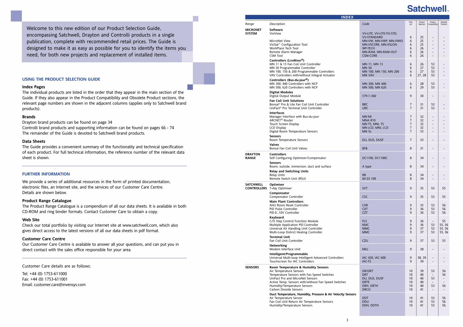
Welcome to this new edition of our Product Selection Guide,encompassing Satchwell, Drayton and Controlli products in a singlepublication, complete with recommended retail prices. The Guide isdesigned to make it as easy as possible for you to identify the items youneed, for both new projects and replacement of installed items.
USING THE PRODUCT SELECTION GUIDE
Index PagesThe individual products are listed in the order that they appear in the main section of theGuide. If they also appear in the Product Compatibility and Obsolete Product sections, therelevant page numbers are shown in the adjacent columns (applies only to Satchwell brandproducts).
BrandsDrayton brand products can be found on page 34Controlli brand products and supporting information can be found on pages 66 - 74The remainder of the Guide is devoted to Satchwell brand products.
Data SheetsThe Guide provides a convenient summary of the functionality and technical specificationof each product. For full technical information, the reference number of the relevant datasheet is shown.
FURTHER INFORMATION
We provide a series of additional resources in the form of printed documentation,electronic files, an Internet site, and the services of our Customer Care Centre.Details are shown below.
Product Range CatalogueThe Product Range Catalogue is a compendium of all our data sheets. It is available in bothCD-ROM and ring binder formats. Contact Customer Care to obtain a copy.
Web SiteCheck our total portfolio by visiting our Internet site at www.satchwell.com, which alsogives direct access to the latest versions of all our data sheets in pdf format.
Customer Care CentreOur Customer Care Centre is available to answer all your questions, and can put you indirect contact with the sales office responsible for your area.
Customer Care details are as follows:
Tel: +44 (0) 1753-611000Fax: +44 (0) 1753-611001Email: [email protected]
PriceList
5
Range Description Code
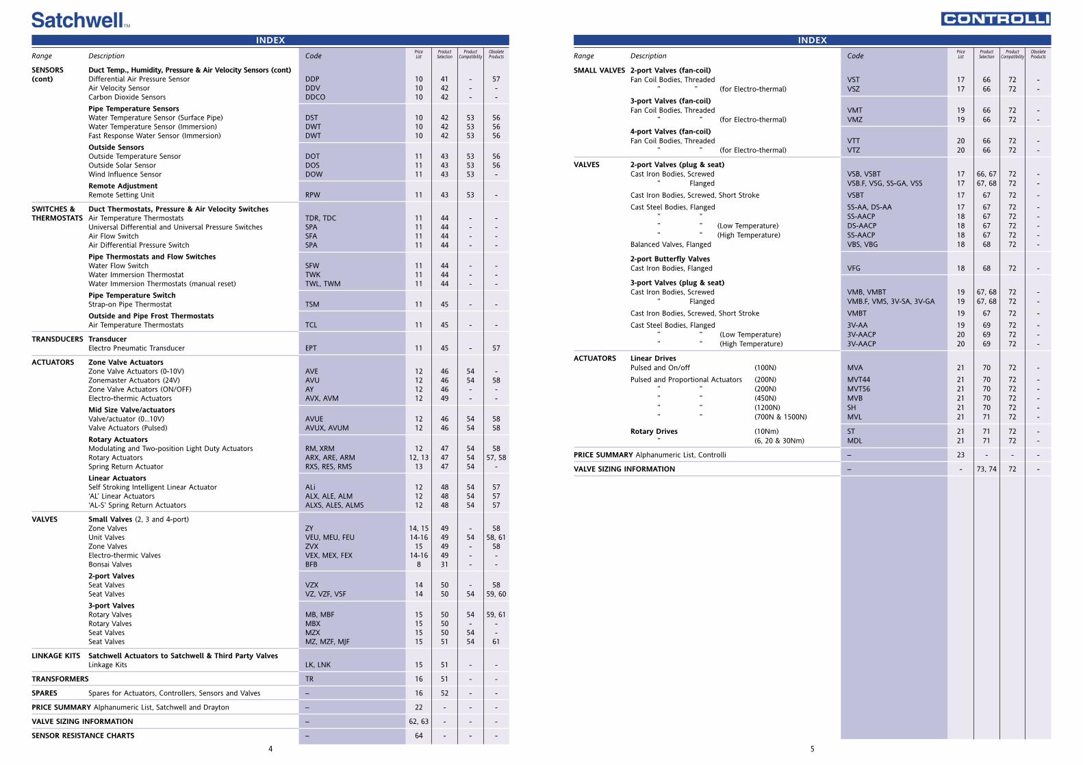
SMALL VALVES 2-port Valves (fan-coil)Fan Coil Bodies, Threaded VST 17 66 72 -
” ” (for Electro-thermal) VSZ 17 66 72 -
3-port Valves (fan-coil)Fan Coil Bodies, Threaded VMT 19 66 72 -
” ” (for Electro-thermal) VMZ 19 66 72 -
4-port Valves (fan-coil)Fan Coil Bodies, Threaded VTT 20 66 72 -
” ” (for Electro-thermal) VTZ 20 66 72 -
VALVES 2-port Valves (plug & seat)Cast Iron Bodies, Screwed VSB, VSBT 17 66, 67 72 -
” Flanged VSB.F, VSG, SS-GA, VSS 17 67, 68 72 -
Cast Iron Bodies, Screwed, Short Stroke VSBT 17 67 72 -
Cast Steel Bodies, Flanged SS-AA, DS-AA 17 67 72 -” ” SS-AACP 18 67 72 -” ” (Low Temperature) DS-AACP 18 67 72 -” ” (High Temperature) SS-AACP 18 67 72 -
Balanced Valves, Flanged VBS, VBG 18 68 72 -
2-port Butterfly ValvesCast Iron Bodies, Flanged VFG 18 68 72 -
3-port Valves (plug & seat)Cast Iron Bodies, Screwed VMB, VMBT 19 67, 68 72 -
” Flanged VMB.F, VMS, 3V-SA, 3V-GA 19 67, 68 72 -
Cast Iron Bodies, Screwed, Short Stroke VMBT 19 67 72 -
Cast Steel Bodies, Flanged 3V-AA 19 69 72 -” ” (Low Temperature) 3V-AACP 20 69 72 -” ” (High Temperature) 3V-AACP 20 69 72 -
ACTUATORS Linear DrivesPulsed and On/off (100N) MVA 21 70 72 -
Pulsed and Proportional Actuators (200N) MVT44 21 70 72 -” ” (200N) MVT56 21 70 72 -” ” (450N) MVB 21 70 72 -” ” (1200N) SH 21 70 72 -” ” (700N & 1500N) MVL 21 71 72 -
Rotary Drives (10Nm) ST 21 71 72 -” (6, 20 & 30Nm) MDL 21 71 72 -
PRICE SUMMARY Alphanumeric List, Controlli – 23 - - -
VALVE SIZING INFORMATION – - 73, 74 72 -
ProductSelection
ProductCompatibility
ObsoleteProducts
INDEX
Range Description Code
SENSORS Duct Temp., Humidity, Pressure & Air Velocity Sensors (cont)(cont) Differential Air Pressure Sensor DDP 10 41 - 57
Air Velocity Sensor DDV 10 42 - -Carbon Dioxide Sensors DDCO 10 42 - -
Pipe Temperature SensorsWater Temperature Sensor (Surface Pipe) DST 10 42 53 56Water Temperature Sensor (Immersion) DWT 10 42 53 56Fast Response Water Sensor (Immersion) DWT 10 42 53 56
Outside SensorsOutside Temperature Sensor DOT 11 43 53 56Outside Solar Sensor DOS 11 43 53 56Wind Influence Sensor DOW 11 43 53 -
Remote AdjustmentRemote Setting Unit RPW 11 43 53 -
SWITCHES & Duct Thermostats, Pressure & Air Velocity SwitchesTHERMOSTATS Air Temperature Thermostats TDR, TDC 11 44 - -
Universal Differential and Universal Pressure Switches SPA 11 44 - -Air Flow Switch SFA 11 44 - -Air Differential Pressure Switch SPA 11 44 - -
Pipe Thermostats and Flow SwitchesWater Flow Switch SFW 11 44 - -Water Immersion Thermostat TWK 11 44 - -Water Immersion Thermostats (manual reset) TWL, TWM 11 44 - -
Pipe Temperature SwitchStrap-on Pipe Thermostat TSM 11 45 - -
Outside and Pipe Frost ThermostatsAir Temperature Thermostats TCL 11 45 - -
TRANSDUCERS TransducerElectro Pneumatic Transducer EPT 11 45 - 57
ACTUATORS Zone Valve ActuatorsZone Valve Actuators (0-10V) AVE 12 46 54 -Zonemaster Actuators (24V) AVU 12 46 54 58Zone Valve Actuators (ON/OFF) AY 12 46 - -Electro-thermic Actuators AVX, AVM 12 49 - -
Mid Size Valve/actuatorsValve/actuator (0...10V) AVUE 12 46 54 58Valve Actuators (Pulsed) AVUX, AVUM 12 46 54 58
Rotary ActuatorsModulating and Two-position Light Duty Actuators RM, XRM 12 47 54 58Rotary Actuators ARX, ARE, ARM 12, 13 47 54 57, 58Spring Return Actuator RXS, RES, RMS 13 47 54 -
Linear ActuatorsSelf Stroking Intelligent Linear Actuator ALi 12 48 54 57‘AL’ Linear Actuators ALX, ALE, ALM 12 48 54 57‘AL-S’ Spring Return Actuators ALXS, ALES, ALMS 12 48 54 57
VALVES Small Valves (2, 3 and 4-port)Zone Valves ZY 14, 15 49 - 58Unit Valves VEU, MEU, FEU 14-16 49 54 58, 61Zone Valves ZVX 15 49 - 58Electro-thermic Valves VEX, MEX, FEX 14-16 49 - -Bonsai Valves BFB 8 31 - -
2-port ValvesSeat Valves VZX 14 50 - 58Seat Valves VZ, VZF, VSF 14 50 54 59, 60
3-port ValvesRotary Valves MB, MBF 15 50 54 59, 61Rotary Valves MBX 15 50 - -Seat Valves MZX 15 50 54 -Seat Valves MZ, MZF, MJF 15 51 54 61
LINKAGE KITS Satchwell Actuators to Satchwell & Third Party ValvesLinkage Kits LK, LNK 15 51 - -
TRANSFORMERS TR 16 51 - -
SPARES Spares for Actuators, Controllers, Sensors and Valves – 16 52 - -
PRICE SUMMARY Alphanumeric List, Satchwell and Drayton – 22 - - -
VALVE SIZING INFORMATION – 62, 63 - - -
SENSOR RESISTANCE CHARTS – 64 - - -
4
ProductSelection
ProductCompatibility
ObsoleteProducts
INDEXPriceList
PriceList
22 23
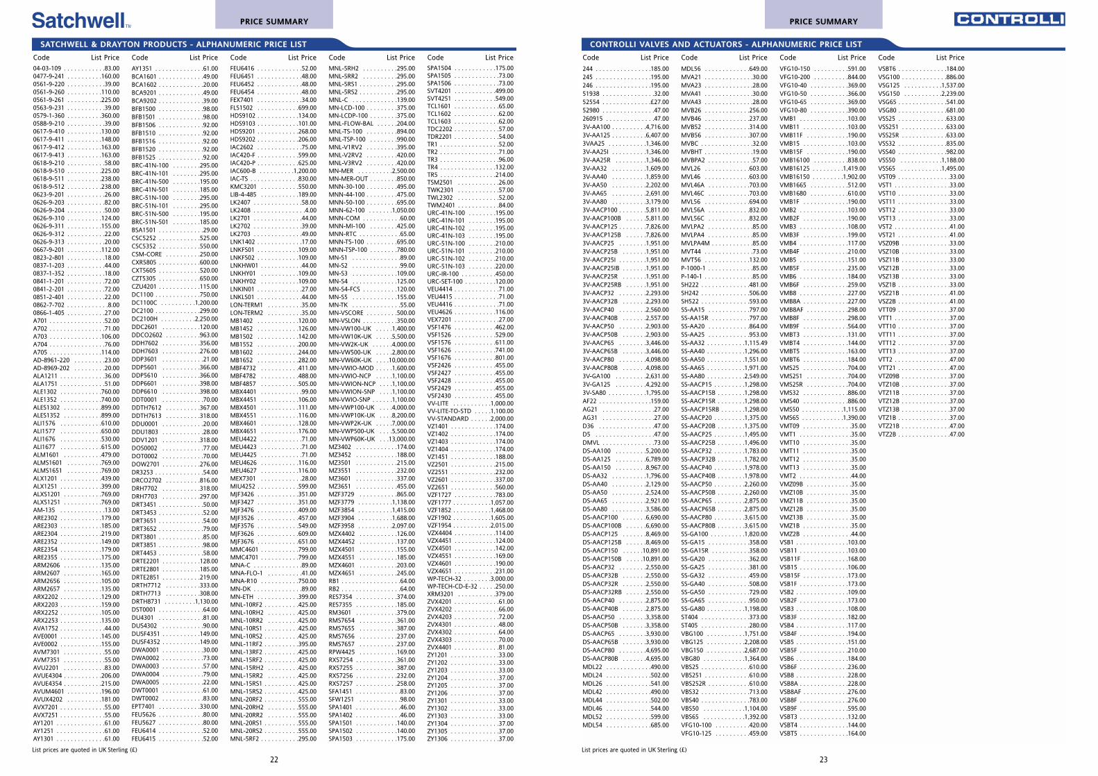
SATCHWELL & DRAYTON PRODUCTS - ALPHANUMERIC PRICE LIST
List prices are quoted in UK Sterling (£) List prices are quoted in UK Sterling (£)
CONTROLLI VALVES AND ACTUATORS - ALPHANUMERIC PRICE LIST
Code List Price
244 . . . . . . . . . . . . . . . .185.00245 . . . . . . . . . . . . . . . .195.00246 . . . . . . . . . . . . . . . .195.0051938 . . . . . . . . . . . . . . .32.0052554 . . . . . . . . . . . . . .£27.0052980 . . . . . . . . . . . . . . .47.00260915 . . . . . . . . . . . . . .47.003V-AA100 . . . . . . . . . .4,716.003V-AA125 . . . . . . . . . .6,407.003VAA25 . . . . . . . . . . .1,346.003V-AA25I . . . . . . . . . .1,346.003V-AA25R . . . . . . . . .1,346.003V-AA32 . . . . . . . . . .1,609.003V-AA40 . . . . . . . . . .1,859.003V-AA50 . . . . . . . . . .2,202.003V-AA65 . . . . . . . . . .2,691.003V-AA80 . . . . . . . . . .3,179.003V-AACP100 . . . . . . . .5,811.003V-AACP100B . . . . . .5,811.003V-AACP125 . . . . . . . .7,826.003V-AACP125B . . . . . .7,826.003V-AACP25 . . . . . . . .1,951.003V-AACP25B . . . . . . .1,951.003V-AACP25I . . . . . . . .1,951.003V-AACP25IB . . . . . . .1,951.003V-AACP25R . . . . . . .1,951.003V-AACP25RB . . . . . .1,951.003V-AACP32 . . . . . . . .2,293.003V-AACP32B . . . . . . .2,293.003V-AACP40 . . . . . . . .2,560.003V-AACP40B . . . . . . .2,557.003V-AACP50 . . . . . . . .2,903.003V-AACP50B . . . . . . .2,903.003V-AACP65 . . . . . . . .3,446.003V-AACP65B . . . . . . .3,446.003V-AACP80 . . . . . . . .4,098.003V-AACP80B . . . . . . .4,098.003V-GA100 . . . . . . . . .2,631.003V-GA125 . . . . . . . . .4,292.003V-SA80 . . . . . . . . . . .1,795.00AF22 . . . . . . . . . . . . . . .159.00AG21 . . . . . . . . . . . . . . .27.00AG31 . . . . . . . . . . . . . . .27.00D36 . . . . . . . . . . . . . . . .47.00D5 . . . . . . . . . . . . . . . . .47.00DMVL . . . . . . . . . . . . . . .73.00DS-AA100 . . . . . . . . .5,200.00DS-AA125 . . . . . . . . .6,789.00DS-AA150 . . . . . . . . .8,967.00DS-AA32 . . . . . . . . . .1,796.00DS-AA40 . . . . . . . . . .2,129.00DS-AA50 . . . . . . . . . .2,524.00DS-AA65 . . . . . . . . . .2,921.00DS-AA80 . . . . . . . . . .3,586.00DS-AACP100 . . . . . . .6,690.00DS-AACP100B . . . . . .6,690.00DS-AACP125 . . . . . . .8,469.00DS-AACP125B . . . . . .8,469.00DS-AACP150 . . . . . .10,891.00DS-AACP150B . . . . .10,891.00DS-AACP32 . . . . . . . .2,550.00DS-AACP32B . . . . . . .2,550.00DS-AACP32R . . . . . . .2,550.00DS-AACP32RB . . . . . .2,550.00DS-AACP40 . . . . . . . .2,875.00DS-AACP40B . . . . . . .2,875.00DS-AACP50 . . . . . . . .3,358.00DS-AACP50B . . . . . . .3,358.00DS-AACP65 . . . . . . . .3,930.00DS-AACP65B . . . . . . .3,930.00DS-AACP80 . . . . . . . .4,695.00DS-AACP80B . . . . . . .4,695.00MDL22 . . . . . . . . . . . . .490.00MDL24 . . . . . . . . . . . . .502.00MDL26 . . . . . . . . . . . . .541.00MDL42 . . . . . . . . . . . . .490.00MDL44 . . . . . . . . . . . . .502.00MDL46 . . . . . . . . . . . . .544.00MDL52 . . . . . . . . . . . . .599.00MDL54 . . . . . . . . . . . . .685.00
Code List Price
MDL56 . . . . . . . . . . . . .649.00MVA21 . . . . . . . . . . . . . .30.00MVA23 . . . . . . . . . . . . . .28.00MVA41 . . . . . . . . . . . . . .30.00MVA43 . . . . . . . . . . . . . .28.00MVB26 . . . . . . . . . . . . .256.00MVB46 . . . . . . . . . . . . .237.00MVB52 . . . . . . . . . . . . .314.00MVB56 . . . . . . . . . . . . .307.00MVBC . . . . . . . . . . . . . . .32.00MVBHT . . . . . . . . . . . . . .19.00MVBPA2 . . . . . . . . . . . . .57.00MVL26 . . . . . . . . . . . . .603.00MVL46 . . . . . . . . . . . . .603.00MVL46A . . . . . . . . . . . .703.00MVL46C . . . . . . . . . . . .703.00MVL56 . . . . . . . . . . . . .694.00MVL56A . . . . . . . . . . . .832.00MVL56C . . . . . . . . . . . .832.00MVLPA2 . . . . . . . . . . . . .85.00MVLPA4 . . . . . . . . . . . . .85.00MVLPA4M . . . . . . . . . . . .85.00MVT44 . . . . . . . . . . . . . .73.00MVT56 . . . . . . . . . . . . .132.00P-1000-1 . . . . . . . . . . . . .85.00P-140-1 . . . . . . . . . . . . . .85.00SH222 . . . . . . . . . . . . . .481.00SH242 . . . . . . . . . . . . . .506.00SH522 . . . . . . . . . . . . . .593.00SS-AA15 . . . . . . . . . . . .797.00SS-AA15R . . . . . . . . . . .797.00SS-AA20 . . . . . . . . . . . .864.00SS-AA25 . . . . . . . . . . . .953.00SS-AA32 . . . . . . . . . . .1,115.49SS-AA40 . . . . . . . . . . .1,296.00SS-AA50 . . . . . . . . . . .1,551.00SS-AA65 . . . . . . . . . . .1,971.00SS-AA80 . . . . . . . . . . .2,549.00SS-AACP15 . . . . . . . . .1,298.00SS-AACP15B . . . . . . . .1,298.00SS-AACP15R . . . . . . . .1,298.00SS-AACP15RB . . . . . . .1,298.00SS-AACP20 . . . . . . . . .1,375.00SS-AACP20B . . . . . . . .1,375.00SS-AACP25 . . . . . . . . .1,495.00SS-AACP25B . . . . . . . .1,496.00SS-AACP32 . . . . . . . . .1,783.00SS-AACP32B . . . . . . . .1,782.00SS-AACP40 . . . . . . . . .1,978.00SS-AACP40B . . . . . . . .1,978.00SS-AACP50 . . . . . . . . .2,260.00SS-AACP50B . . . . . . . .2,260.00SS-AACP65 . . . . . . . . .2,875.00SS-AACP65B . . . . . . . .2,875.00SS-AACP80 . . . . . . . . .3,615.00SS-AACP80B . . . . . . . .3,615.00SS-GA100 . . . . . . . . . .1,820.00SS-GA15 . . . . . . . . . . . .358.00SS-GA15R . . . . . . . . . . .358.00SS-GA20 . . . . . . . . . . . .362.00SS-GA25 . . . . . . . . . . . .381.00SS-GA32 . . . . . . . . . . . .459.00SS-GA40 . . . . . . . . . . . .508.00SS-GA50 . . . . . . . . . . . .729.00SS-GA65 . . . . . . . . . . . .950.00SS-GA80 . . . . . . . . . . .1,198.00ST404 . . . . . . . . . . . . . .373.00ST405 . . . . . . . . . . . . . .280.00VBG100 . . . . . . . . . . .1,751.00VBG125 . . . . . . . . . . .2,208.00VBG150 . . . . . . . . . . .2,687.00VBG80 . . . . . . . . . . . .1,364.00VBS25 . . . . . . . . . . . . . .610.00VBS251 . . . . . . . . . . . . .610.00VBS252R . . . . . . . . . . . .610.00VBS32 . . . . . . . . . . . . . .713.00VBS40 . . . . . . . . . . . . . .783.00VBS50 . . . . . . . . . . . .1,104.00VBS65 . . . . . . . . . . . .1,392.00VFG10-100 . . . . . . . . . .420.00VFG10-125 . . . . . . . . . .459.00
Code List Price
VFG10-150 . . . . . . . . . .591.00VFG10-200 . . . . . . . . . .844.00VFG10-40 . . . . . . . . . . .369.00VFG10-50 . . . . . . . . . . .366.00VFG10-65 . . . . . . . . . . .369.00VFG10-80 . . . . . . . . . . .390.00VMB1 . . . . . . . . . . . . . .103.00VMB11 . . . . . . . . . . . . .103.00VMB11F . . . . . . . . . . . .190.00VMB15 . . . . . . . . . . . . .103.00VMB15F . . . . . . . . . . . .190.00VMB16100 . . . . . . . . . .838.00VMB16125 . . . . . . . . .1,419.00VMB16150 . . . . . . . . .1,902.00VMB1665 . . . . . . . . . . .512.00VMB1680 . . . . . . . . . . .610.00VMB1F . . . . . . . . . . . . .190.00VMB2 . . . . . . . . . . . . . .103.00VMB2F . . . . . . . . . . . . .190.00VMB3 . . . . . . . . . . . . . .108.00VMB3F . . . . . . . . . . . . .199.00VMB4 . . . . . . . . . . . . . .117.00VMB4F . . . . . . . . . . . . .210.00VMB5 . . . . . . . . . . . . . .151.00VMB5F . . . . . . . . . . . . .235.00VMB6 . . . . . . . . . . . . . .184.00VMB6F . . . . . . . . . . . . .259.00VMB8 . . . . . . . . . . . . . .227.00VMB8A . . . . . . . . . . . . .227.00VMB8AF . . . . . . . . . . . .298.00VMB8F . . . . . . . . . . . . .298.00VMB9F . . . . . . . . . . . . .564.00VMBT3 . . . . . . . . . . . . .131.00VMBT4 . . . . . . . . . . . . .144.00VMBT5 . . . . . . . . . . . . .163.00VMBT6 . . . . . . . . . . . . .184.00VMS25 . . . . . . . . . . . . .704.00VMS251 . . . . . . . . . . . .704.00VMS25R . . . . . . . . . . . .704.00VMS32 . . . . . . . . . . . . .886.00VMS40 . . . . . . . . . . . . .886.00VMS50 . . . . . . . . . . . .1,115.00VMS65 . . . . . . . . . . . .1,390.00VMT09 . . . . . . . . . . . . . .35.00VMT1 . . . . . . . . . . . . . . .35.00VMT10 . . . . . . . . . . . . . .35.00VMT11 . . . . . . . . . . . . . .35.00VMT12 . . . . . . . . . . . . . .35.00VMT13 . . . . . . . . . . . . . .35.00VMT2 . . . . . . . . . . . . . . .44.00VMZ09B . . . . . . . . . . . . .35.00VMZ10B . . . . . . . . . . . . .35.00VMZ11B . . . . . . . . . . . . .35.00VMZ12B . . . . . . . . . . . . .35.00VMZ13B . . . . . . . . . . . . .35.00VMZ1B . . . . . . . . . . . . . .35.00VMZ2B . . . . . . . . . . . . . .44.00VSB1 . . . . . . . . . . . . . . .103.00VSB11 . . . . . . . . . . . . . .103.00VSB11F . . . . . . . . . . . . .168.00VSB15 . . . . . . . . . . . . . .106.00VSB15F . . . . . . . . . . . . .173.00VSB1F . . . . . . . . . . . . . .173.00VSB2 . . . . . . . . . . . . . . .109.00VSB2F . . . . . . . . . . . . . .173.00VSB3 . . . . . . . . . . . . . . .108.00VSB3F . . . . . . . . . . . . . .182.00VSB4 . . . . . . . . . . . . . . .117.00VSB4F . . . . . . . . . . . . . .194.00VSB5 . . . . . . . . . . . . . . .151.00VSB5F . . . . . . . . . . . . . .210.00VSB6 . . . . . . . . . . . . . . .184.00VSB6F . . . . . . . . . . . . . .236.00VSB8 . . . . . . . . . . . . . . .228.00VSB8A . . . . . . . . . . . . . .228.00VSB8AF . . . . . . . . . . . . .276.00VSB8F . . . . . . . . . . . . . .276.00VSB9F . . . . . . . . . . . . . .595.00VSBT3 . . . . . . . . . . . . . .132.00VSBT4 . . . . . . . . . . . . . .144.00VSBT5 . . . . . . . . . . . . . .164.00
Code List Price
VSBT6 . . . . . . . . . . . . . .184.00VSG100 . . . . . . . . . . . . .886.00VSG125 . . . . . . . . . . .1,537.00VSG150 . . . . . . . . . . .2,239.00VSG65 . . . . . . . . . . . . . .541.00VSG80 . . . . . . . . . . . . . .681.00VSS25 . . . . . . . . . . . . . .633.00VSS251 . . . . . . . . . . . . .633.00VSS25R . . . . . . . . . . . . .633.00VSS32 . . . . . . . . . . . . . .835.00VSS40 . . . . . . . . . . . . . .982.00VSS50 . . . . . . . . . . . .1,188.00VSS65 . . . . . . . . . . . .1,495.00VST09 . . . . . . . . . . . . . . .33.00VST1 . . . . . . . . . . . . . . . .33.00VST10 . . . . . . . . . . . . . . .33.00VST11 . . . . . . . . . . . . . . .33.00VST12 . . . . . . . . . . . . . . .33.00VST13 . . . . . . . . . . . . . . .33.00VST2 . . . . . . . . . . . . . . . .41.00VST21 . . . . . . . . . . . . . . .41.00VSZ09B . . . . . . . . . . . . . .33.00VSZ10B . . . . . . . . . . . . . .33.00VSZ11B . . . . . . . . . . . . . .33.00VSZ12B . . . . . . . . . . . . . .33.00VSZ13B . . . . . . . . . . . . . .33.00VSZ1B . . . . . . . . . . . . . . .33.00VSZ21B . . . . . . . . . . . . . .41.00VSZ2B . . . . . . . . . . . . . . .41.00VTT09 . . . . . . . . . . . . . . .37.00VTT1 . . . . . . . . . . . . . . . .37.00VTT10 . . . . . . . . . . . . . . .37.00VTT11 . . . . . . . . . . . . . . .37.00VTT12 . . . . . . . . . . . . . . .37.00VTT13 . . . . . . . . . . . . . . .37.00VTT2 . . . . . . . . . . . . . . . .47.00VTT21 . . . . . . . . . . . . . . .47.00VTZ09B . . . . . . . . . . . . . .37.00VTZ10B . . . . . . . . . . . . . .37.00VTZ11B . . . . . . . . . . . . . .37.00VTZ12B . . . . . . . . . . . . . .37.00VTZ13B . . . . . . . . . . . . . .37.00VTZ1B . . . . . . . . . . . . . . .37.00VTZ21B . . . . . . . . . . . . . .47.00VTZ2B . . . . . . . . . . . . . . .47.00
Code List Price
04-03-109 . . . . . . . . . . . .83.000477-9-241 . . . . . . . . . .160.000561-9-220 . . . . . . . . . . .39.000561-9-260 . . . . . . . . . .110.000561-9-261 . . . . . . . . . .225.000563-9-231 . . . . . . . . . . .39.000579-1-360 . . . . . . . . . .360.000588-9-210 . . . . . . . . . . .39.000617-9-410 . . . . . . . . . .130.000617-9-411 . . . . . . . . . .148.000617-9-412 . . . . . . . . . .163.000617-9-413 . . . . . . . . . .163.000618-9-210 . . . . . . . . . . .58.000618-9-510 . . . . . . . . . .225.000618-9-511 . . . . . . . . . .238.000618-9-512 . . . . . . . . . .238.000623-9-201 . . . . . . . . . . .26.000626-9-203 . . . . . . . . . . .82.000626-9-204 . . . . . . . . . . .50.000626-9-310 . . . . . . . . . .124.000626-9-311 . . . . . . . . . .155.000626-9-312 . . . . . . . . . . .22.000626-9-313 . . . . . . . . . . .20.000667-9-201 . . . . . . . . . .112.000823-2-801 . . . . . . . . . . .18.000837-1-203 . . . . . . . . . . .44.000837-1-352 . . . . . . . . . . .18.000841-1-201 . . . . . . . . . . .72.000841-2-201 . . . . . . . . . . .72.000851-2-401 . . . . . . . . . . .22.000862-7-702 . . . . . . . . . . . .8.000866-1-405 . . . . . . . . . . .27.00A701 . . . . . . . . . . . . . . . .52.00A702 . . . . . . . . . . . . . . . .71.00A703 . . . . . . . . . . . . . . .106.00A704 . . . . . . . . . . . . . . . .76.00A705 . . . . . . . . . . . . . . .114.00AD-8961-220 . . . . . . . . .23.00AD-8969-202 . . . . . . . . .20.00ALA1211 . . . . . . . . . . . . .36.00ALA1751 . . . . . . . . . . . . .51.00ALE1302 . . . . . . . . . . . .760.00ALE1352 . . . . . . . . . . . .740.00ALES1302 . . . . . . . . . . .899.00ALES1352 . . . . . . . . . . .899.00ALI1576 . . . . . . . . . . . .610.00ALI1577 . . . . . . . . . . . .650.00ALI1676 . . . . . . . . . . . .530.00ALI1677 . . . . . . . . . . . .615.00ALM1601 . . . . . . . . . . .479.00ALMS1601 . . . . . . . . . .769.00ALMS1651 . . . . . . . . . .769.00ALX1201 . . . . . . . . . . . .439.00ALX1251 . . . . . . . . . . . .399.00ALXS1201 . . . . . . . . . . .769.00ALXS1251 . . . . . . . . . . .769.00AM-135 . . . . . . . . . . . . .13.00ARE2302 . . . . . . . . . . . .179.00ARE2303 . . . . . . . . . . . .185.00ARE2304 . . . . . . . . . . . .219.00ARE2352 . . . . . . . . . . . .149.00ARE2354 . . . . . . . . . . . .179.00ARE2355 . . . . . . . . . . . .175.00ARM2606 . . . . . . . . . . .135.00ARM2607 . . . . . . . . . . .165.00ARM2656 . . . . . . . . . . .105.00ARM2657 . . . . . . . . . . .135.00ARX2202 . . . . . . . . . . . .129.00ARX2203 . . . . . . . . . . . .159.00ARX2252 . . . . . . . . . . . .105.00ARX2253 . . . . . . . . . . . .135.00AVA1752 . . . . . . . . . . . . .44.00AVE0001 . . . . . . . . . . . .145.00AVE0002 . . . . . . . . . . . .155.00AVM7301 . . . . . . . . . . . .55.00AVM7351 . . . . . . . . . . . .55.00AVU2201 . . . . . . . . . . . .83.00AVUE4304 . . . . . . . . . . .206.00AVUE4354 . . . . . . . . . . .215.00AVUM4601 . . . . . . . . . .196.00AVUX4202 . . . . . . . . . .181.00AVX7201 . . . . . . . . . . . . .55.00AVX7251 . . . . . . . . . . . . .55.00AY1201 . . . . . . . . . . . . . .61.00AY1251 . . . . . . . . . . . . . .61.00AY1301 . . . . . . . . . . . . . .61.00
Code List Price
AY1351 . . . . . . . . . . . . . .61.00BCA1601 . . . . . . . . . . . . .49.00BCA1602 . . . . . . . . . . . . .20.00BCA9201 . . . . . . . . . . . . .49.00BCA9202 . . . . . . . . . . . . .39.00BFB1500 . . . . . . . . . . . . .98.00BFB1501 . . . . . . . . . . . . .98.00BFB1506 . . . . . . . . . . . . .92.00BFB1510 . . . . . . . . . . . . .92.00BFB1516 . . . . . . . . . . . . .92.00BFB1520 . . . . . . . . . . . . .92.00BFB1525 . . . . . . . . . . . . .92.00BRC-41N-100 . . . . . . . .295.00BRC-41N-101 . . . . . . . .295.00BRC-41N-500 . . . . . . . .195.00BRC-41N-501 . . . . . . . .185.00BRC-51N-100 . . . . . . . .295.00BRC-51N-101 . . . . . . . .295.00BRC-51N-500 . . . . . . . .195.00BRC-51N-501 . . . . . . . .185.00BSA1501 . . . . . . . . . . . . .29.00CSC5252 . . . . . . . . . . . .525.00CSC5352 . . . . . . . . . . . .550.00CSM-CORE . . . . . . . . . .250.00CXR5805 . . . . . . . . . . . .600.00CXT5605 . . . . . . . . . . . .520.00CZT5305 . . . . . . . . . . . .650.00CZU4201 . . . . . . . . . . . .115.00DC1100 . . . . . . . . . . . . .750.00DC1100C . . . . . . . . . .1,200.00DC2100 . . . . . . . . . . . . .299.00DC2100H . . . . . . . . . .2,250.00DDC2601 . . . . . . . . . . .120.00DDCO2602 . . . . . . . . . .963.00DDH7602 . . . . . . . . . . .356.00DDH7603 . . . . . . . . . . .276.00DDP3601 . . . . . . . . . . . .21.00DDP5601 . . . . . . . . . . .366.00DDP5610 . . . . . . . . . . .366.00DDP6601 . . . . . . . . . . .398.00DDP6610 . . . . . . . . . . .398.00DDT0001 . . . . . . . . . . . .70.00DDTH7612 . . . . . . . . . .367.00DDTH7613 . . . . . . . . . .318.00DDU0001 . . . . . . . . . . . .20.00DDU1803 . . . . . . . . . . . .28.00DDV1201 . . . . . . . . . . .318.00DOS0002 . . . . . . . . . . . .77.00DOT0002 . . . . . . . . . . . .70.00DOW2701 . . . . . . . . . . .276.00DR3253 . . . . . . . . . . . . . .54.00DRCO2702 . . . . . . . . . .816.00DRH7702 . . . . . . . . . . .318.00DRH7703 . . . . . . . . . . .297.00DRT3451 . . . . . . . . . . . . .50.00DRT3453 . . . . . . . . . . . . .52.00DRT3651 . . . . . . . . . . . . .54.00DRT3652 . . . . . . . . . . . . .79.00DRT3801 . . . . . . . . . . . . .85.00DRT3851 . . . . . . . . . . . . .98.00DRT4453 . . . . . . . . . . . . .58.00DRTE2201 . . . . . . . . . . .128.00DRTE2801 . . . . . . . . . . .185.00DRTE2851 . . . . . . . . . . .219.00DRTH7712 . . . . . . . . . .333.00DRTH7713 . . . . . . . . . .308.00DRTH8731 . . . . . . . . .1,130.00DST0001 . . . . . . . . . . . . .64.00DU4301 . . . . . . . . . . . . .81.00DUS4302 . . . . . . . . . . . .90.00DUSF4351 . . . . . . . . . . .149.00DUSF4352 . . . . . . . . . . .149.00DWA0001 . . . . . . . . . . . .30.00DWA0002 . . . . . . . . . . . .73.00DWA0003 . . . . . . . . . . . .57.00DWA0004 . . . . . . . . . . . .79.00DWA0005 . . . . . . . . . . . .22.00DWT0001 . . . . . . . . . . . .61.00DWT0002 . . . . . . . . . . . .83.00EPT7401 . . . . . . . . . . . .330.00FEU5626 . . . . . . . . . . . . .80.00FEU5627 . . . . . . . . . . . . .80.00FEU6414 . . . . . . . . . . . . .52.00FEU6415 . . . . . . . . . . . . .52.00
Code List Price
FEU6416 . . . . . . . . . . . . .52.00FEU6451 . . . . . . . . . . . . .48.00FEU6452 . . . . . . . . . . . . .48.00FEU6454 . . . . . . . . . . . . .48.00FEX7401 . . . . . . . . . . . . .34.00FLS1502 . . . . . . . . . . . .699.00HDS9102 . . . . . . . . . . . .134.00HDS9103 . . . . . . . . . . . .101.00HDS9201 . . . . . . . . . . . .268.00HDS9202 . . . . . . . . . . . .206.00IAC2602 . . . . . . . . . . . . .75.00IAC420-F . . . . . . . . . . . .599.00IAC420-P . . . . . . . . . . . .625.00IAC600-B . . . . . . . . . .1,200.00IAC-TS . . . . . . . . . . . . . .830.00KMC3201 . . . . . . . . . . .550.00LIB-4-485 . . . . . . . . . . .189.00LK2407 . . . . . . . . . . . . . .58.00LK2408 . . . . . . . . . . . . . . .4.00LK2701 . . . . . . . . . . . . . .44.00LK2702 . . . . . . . . . . . . . .39.00LK2703 . . . . . . . . . . . . . .49.00LNK1402 . . . . . . . . . . . . .17.00LNKFS01 . . . . . . . . . . . .109.00LNKFS02 . . . . . . . . . . . .109.00LNKHW01 . . . . . . . . . . . .44.00LNKHY01 . . . . . . . . . . .109.00LNKHY02 . . . . . . . . . . .109.00LNKIN01 . . . . . . . . . . . . .27.00LNKLS01 . . . . . . . . . . . . .44.00LON-TERM1 . . . . . . . . . .35.00LON-TERM2 . . . . . . . . . .35.00MB1402 . . . . . . . . . . . .120.00MB1452 . . . . . . . . . . . .126.00MB1502 . . . . . . . . . . . .142.00MB1552 . . . . . . . . . . . .200.00MB1602 . . . . . . . . . . . .244.00MB1652 . . . . . . . . . . . .282.00MBF4732 . . . . . . . . . . .411.00MBF4782 . . . . . . . . . . .488.00MBF4857 . . . . . . . . . . .505.00MBX4401 . . . . . . . . . . . .99.00MBX4451 . . . . . . . . . . .106.00MBX4501 . . . . . . . . . . .111.00MBX4551 . . . . . . . . . . .116.00MBX4601 . . . . . . . . . . .128.00MBX4651 . . . . . . . . . . .176.00MEU4422 . . . . . . . . . . . .71.00MEU4423 . . . . . . . . . . . .71.00MEU4425 . . . . . . . . . . . .71.00MEU4626 . . . . . . . . . . .116.00MEU4627 . . . . . . . . . . .116.00MEX7301 . . . . . . . . . . . .28.00MIU4252 . . . . . . . . . . . .599.00MJF3426 . . . . . . . . . . . .351.00MJF3427 . . . . . . . . . . . .351.00MJF3476 . . . . . . . . . . . .409.00MJF3526 . . . . . . . . . . . .457.00MJF3576 . . . . . . . . . . . .549.00MJF3626 . . . . . . . . . . . .609.00MJF3676 . . . . . . . . . . . .651.00MMC4601 . . . . . . . . . . .799.00MMC4701 . . . . . . . . . . .799.00MNA-C . . . . . . . . . . . . . .89.00MNA-FLO-1 . . . . . . . . . .41.00MNA-R10 . . . . . . . . . . .750.00MN-DK . . . . . . . . . . . . . .89.00MN-ETH . . . . . . . . . . . .399.00MNL-10RF2 . . . . . . . . . .425.00MNL-10RH2 . . . . . . . . .425.00MNL-10RR2 . . . . . . . . .425.00MNL-10RS1 . . . . . . . . . .425.00MNL-10RS2 . . . . . . . . . .425.00MNL-11RF2 . . . . . . . . . .395.00MNL-13RF2 . . . . . . . . . .425.00MNL-15RF2 . . . . . . . . . .425.00MNL-15RH2 . . . . . . . . .425.00MNL-15RR2 . . . . . . . . .425.00MNL-15RS1 . . . . . . . . . .425.00MNL-15RS2 . . . . . . . . . .425.00MNL-20RF2 . . . . . . . . . .555.00MNL-20RH2 . . . . . . . . .555.00MNL-20RR2 . . . . . . . . .555.00MNL-20RS1 . . . . . . . . . .555.00MNL-20RS2 . . . . . . . . . .555.00MNL-5RF2 . . . . . . . . . . .295.00
Code List Price
MNL-5RH2 . . . . . . . . . .295.00MNL-5RR2 . . . . . . . . . .295.00MNL-5RS1 . . . . . . . . . . .295.00MNL-5RS2 . . . . . . . . . . .295.00MNL-C . . . . . . . . . . . . .139.00MN-LCD-100 . . . . . . . . .375.00MN-LCDP-100 . . . . . . . .375.00MNL-FLOW-BAL . . . . . .204.00MNL-TS-100 . . . . . . . . .894.00MNL-TSP-100 . . . . . . . .990.00MNL-V1RV2 . . . . . . . . .395.00MNL-V2RV2 . . . . . . . . .420.00MNL-V3RV2 . . . . . . . . .420.00MN-MER . . . . . . . . . .2,500.00MN-MER-OUT . . . . . . . .850.00MNN-30-100 . . . . . . . . .495.00MNN-44-100 . . . . . . . . .475.00MNN-50-100 . . . . . . . . .695.00MNN-62-100 . . . . . . .1,050.00MNN-COM . . . . . . . . . . .60.00MNN-MI-100 . . . . . . . .425.00MNN-RTC . . . . . . . . . . . .65.00MNN-TS-100 . . . . . . . . .695.00MNN-TSP-100 . . . . . . . .780.00MN-S1 . . . . . . . . . . . . . .89.00MN-S2 . . . . . . . . . . . . . .99.00MN-S3 . . . . . . . . . . . . .109.00MN-S4 . . . . . . . . . . . . .125.00MN-S4-FCS . . . . . . . . . .120.00MN-S5 . . . . . . . . . . . . .155.00MN-TK . . . . . . . . . . . . . .55.00MN-VSCORE . . . . . . . . .500.00MN-VSLON . . . . . . . . . .350.00MN-VW100-UK . . . . .1,400.00MN-VW10K-UK . . . . .5,500.00MN-VW2K-UK . . . . . .4,000.00MN-VW500-UK . . . . .2,800.00MN-VW60K-UK . . . .10,000.00MN-VWIO-MOD . . . . .1,600.00MN-VWIO-NCP . . . . .1,100.00MN-VWION-NCP . . . .1,100.00MN-VWION-SNP . . . .1,100.00MN-VWIO-SNP . . . . . .1,100.00MN-VWP100-UK . . . .4,000.00MN-VWP10K-UK . . . .8,200.00MN-VWP2K-UK . . . . .7,000.00MN-VWP500-UK . . . .5,500.00MN-VWP60K-UK . . .13,000.00MZ3402 . . . . . . . . . . . .174.00MZ3452 . . . . . . . . . . . .188.00MZ3501 . . . . . . . . . . . .215.00MZ3551 . . . . . . . . . . . .232.00MZ3601 . . . . . . . . . . . .337.00MZ3651 . . . . . . . . . . . .455.00MZF3729 . . . . . . . . . . .865.00MZF3779 . . . . . . . . . .1,138.00MZF3854 . . . . . . . . . .1,415.00MZF3904 . . . . . . . . . .1,688.00MZF3958 . . . . . . . . . .2,097.00MZX4402 . . . . . . . . . . .126.00MZX4452 . . . . . . . . . . .137.00MZX4501 . . . . . . . . . . .155.00MZX4551 . . . . . . . . . . .185.00MZX4601 . . . . . . . . . . .203.00MZX4651 . . . . . . . . . . .245.00RB1 . . . . . . . . . . . . . . . . .64.00RB2 . . . . . . . . . . . . . . . . .64.00RES7354 . . . . . . . . . . . .374.00RES7355 . . . . . . . . . . . .185.00RM3601 . . . . . . . . . . . .379.00RMS7654 . . . . . . . . . . .361.00RMS7655 . . . . . . . . . . .387.00RMS7656 . . . . . . . . . . .237.00RMS7657 . . . . . . . . . . .237.00RPW4425 . . . . . . . . . . .169.00RXS7254 . . . . . . . . . . . .361.00RXS7255 . . . . . . . . . . . .387.00RXS7256 . . . . . . . . . . . .232.00RXS7257 . . . . . . . . . . . .258.00SFA1451 . . . . . . . . . . . . .83.00SFW1251 . . . . . . . . . . . .98.00SPA1401 . . . . . . . . . . . . .46.00SPA1402 . . . . . . . . . . . . .46.00SPA1501 . . . . . . . . . . . .140.00SPA1502 . . . . . . . . . . . .140.00SPA1503 . . . . . . . . . . . .175.00
Code List PriceSPA1504 . . . . . . . . . . . .175.00SPA1505 . . . . . . . . . . . . .73.00SPA1506 . . . . . . . . . . . . .73.00SVT4201 . . . . . . . . . . . .499.00SVT4251 . . . . . . . . . . . .549.00TCL1601 . . . . . . . . . . . . .65.00TCL1602 . . . . . . . . . . . . .62.00TCL1603 . . . . . . . . . . . . .62.00TDC2202 . . . . . . . . . . . . .57.00TDR2201 . . . . . . . . . . . . .54.00TR1 . . . . . . . . . . . . . . . . .52.00TR2 . . . . . . . . . . . . . . . . .71.00TR3 . . . . . . . . . . . . . . . . .96.00TR4 . . . . . . . . . . . . . . . .132.00TR5 . . . . . . . . . . . . . . . .214.00TSM2501 . . . . . . . . . . . .26.00TWK2301 . . . . . . . . . . . .57.00TWL2302 . . . . . . . . . . . .52.00TWM2401 . . . . . . . . . . . .84.00URC-41N-100 . . . . . . . .195.00URC-41N-101 . . . . . . . .195.00URC-41N-102 . . . . . . . .195.00URC-41N-103 . . . . . . . .195.00URC-51N-100 . . . . . . . .210.00URC-51N-101 . . . . . . . .210.00URC-51N-102 . . . . . . . .210.00URC-51N-103 . . . . . . . .220.00URC-IR-100 . . . . . . . . . .450.00URC-SET-100 . . . . . . . . .120.00VEU4414 . . . . . . . . . . . . .71.00VEU4415 . . . . . . . . . . . . .71.00VEU4416 . . . . . . . . . . . . .71.00VEU4626 . . . . . . . . . . . .116.00VEX7201 . . . . . . . . . . . . .27.00VSF1476 . . . . . . . . . . . .462.00VSF1526 . . . . . . . . . . . .529.00VSF1576 . . . . . . . . . . . .611.00VSF1626 . . . . . . . . . . . .741.00VSF1676 . . . . . . . . . . . .801.00VSF2426 . . . . . . . . . . . .455.00VSF2427 . . . . . . . . . . . .455.00VSF2428 . . . . . . . . . . . .455.00VSF2429 . . . . . . . . . . . .455.00VSF2430 . . . . . . . . . . . .455.00VV-LITE . . . . . . . . . . .1,000.00VV-LITE-TO-STD . . . . .1,100.00VV-STANDARD . . . . . .2,000.00VZ1401 . . . . . . . . . . . . .174.00VZ1402 . . . . . . . . . . . . .174.00VZ1403 . . . . . . . . . . . . .174.00VZ1404 . . . . . . . . . . . . .174.00VZ1451 . . . . . . . . . . . . .188.00VZ2501 . . . . . . . . . . . . .215.00VZ2551 . . . . . . . . . . . . .232.00VZ2601 . . . . . . . . . . . . .337.00VZ2651 . . . . . . . . . . . . .560.00VZF1727 . . . . . . . . . . . .783.00VZF1777 . . . . . . . . . . .1,057.00VZF1852 . . . . . . . . . . .1,468.00VZF1902 . . . . . . . . . . .1,605.00VZF1954 . . . . . . . . . . .2,015.00VZX4404 . . . . . . . . . . . .114.00VZX4451 . . . . . . . . . . . .124.00VZX4501 . . . . . . . . . . . .142.00VZX4551 . . . . . . . . . . . .169.00VZX4601 . . . . . . . . . . . .190.00VZX4651 . . . . . . . . . . . .231.00WP-TECH-32 . . . . . . . .3,000.00WP-TECH-CD-E-32 . . . . .250.00XRM3201 . . . . . . . . . . .379.00ZVX4201 . . . . . . . . . . . . .61.00ZVX4202 . . . . . . . . . . . . .66.00ZVX4203 . . . . . . . . . . . . .72.00ZVX4301 . . . . . . . . . . . . .48.00ZVX4302 . . . . . . . . . . . . .64.00ZVX4303 . . . . . . . . . . . . .70.00ZVX4401 . . . . . . . . . . . . .81.00ZY1201 . . . . . . . . . . . . . .33.00ZY1202 . . . . . . . . . . . . . .33.00ZY1203 . . . . . . . . . . . . . .33.00ZY1204 . . . . . . . . . . . . . .37.00ZY1205 . . . . . . . . . . . . . .37.00ZY1206 . . . . . . . . . . . . . .37.00ZY1301 . . . . . . . . . . . . . .33.00ZY1302 . . . . . . . . . . . . . .33.00ZY1303 . . . . . . . . . . . . . .33.00ZY1304 . . . . . . . . . . . . . .37.00ZY1305 . . . . . . . . . . . . . .37.00ZY1306 . . . . . . . . . . . . . .37.00
PRICE SUMMARY PRICE SUMMARY
Software
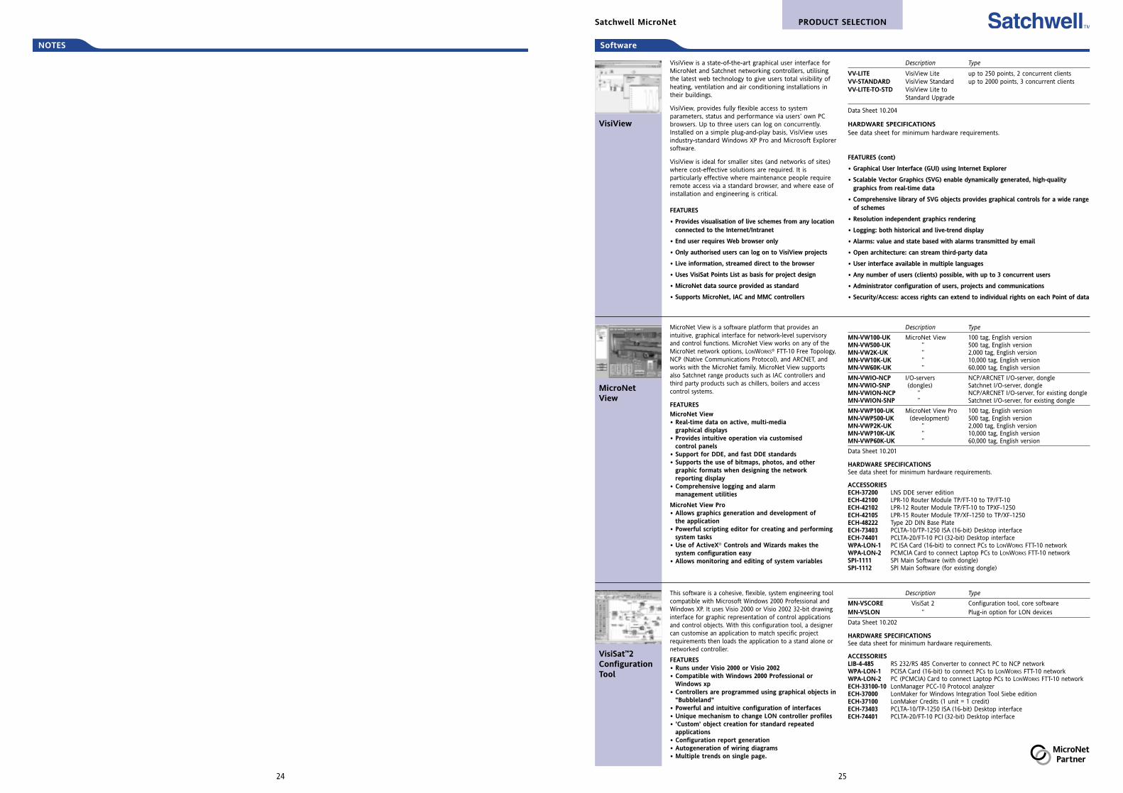
VisiView
VisiView is a state-of-the-art graphical user interface forMicroNet and Satchnet networking controllers, utilisingthe latest web technology to give users total visibility ofheating, ventilation and air conditioning installations intheir buildings.
VisiView, provides fully flexible access to systemparameters, status and performance via users’ own PCbrowsers. Up to three users can log on concurrently.Installed on a simple plug-and-play basis, VisiView usesindustry-standard Windows XP Pro and Microsoft Explorersoftware.
VisiView is ideal for smaller sites (and networks of sites)where cost-effective solutions are required. It isparticularly effective where maintenance people requireremote access via a standard browser, and where ease ofinstallation and engineering is critical.
FEATURES
• Provides visualisation of live schemes from any locationconnected to the Internet/Intranet
• End user requires Web browser only
• Only authorised users can log on to VisiView projects
• Live information, streamed direct to the browser
• Uses VisiSat Points List as basis for project design
• MicroNet data source provided as standard
• Supports MicroNet, IAC and MMC controllers
Description Type
VV-LITE VisiView Lite up to 250 points, 2 concurrent clientsVV-STANDARD VisiView Standard up to 2000 points, 3 concurrent clientsVV-LITE-TO-STD VisiView Lite to
Standard Upgrade
Data Sheet 10.204
HARDWARE SPECIFICATIONSSee data sheet for minimum hardware requirements.
FEATURES (cont)
• Graphical User Interface (GUI) using Internet Explorer
• Scalable Vector Graphics (SVG) enable dynamically generated, high-qualitygraphics from real-time data
• Comprehensive library of SVG objects provides graphical controls for a wide rangeof schemes
• Resolution independent graphics rendering
• Logging: both historical and live-trend display
• Alarms: value and state based with alarms transmitted by email
• Open architecture: can stream third-party data
• User interface available in multiple languages
• Any number of users (clients) possible, with up to 3 concurrent users
• Administrator configuration of users, projects and communications
• Security/Access: access rights can extend to individual rights on each Point of data
PRODUCT SELECTIONSatchwell MicroNet
MicroNetView
MicroNet View is a software platform that provides anintuitive, graphical interface for network-level supervisoryand control functions. MicroNet View works on any of theMicroNet network options, LONWORKS® FTT-10 Free Topology,NCP (Native Communications Protocol), and ARCNET, andworks with the MicroNet family. MicroNet View supportsalso Satchnet range products such as IAC controllers andthird party products such as chillers, boilers and accesscontrol systems.
FEATURES
MicroNet View• Real-time data on active, multi-media
graphical displays• Provides intuitive operation via customised
control panels• Support for DDE, and fast DDE standards• Supports the use of bitmaps, photos, and other
graphic formats when designing the networkreporting display
• Comprehensive logging and alarmmanagement utilities
MicroNet View Pro• Allows graphics generation and development of
the application• Powerful scripting editor for creating and performing
system tasks• Use of ActiveX® Controls and Wizards makes the
system configuration easy• Allows monitoring and editing of system variables
Description Type
MN-VW100-UK MicroNet View 100 tag, English versionMN-VW500-UK ” 500 tag, English versionMN-VW2K-UK ” 2,000 tag, English versionMN-VW10K-UK ” 10,000 tag, English versionMN-VW60K-UK ” 60,000 tag, English version
MN-VWIO-NCP I/O-servers NCP/ARCNET I/O-server, dongleMN-VWIO-SNP (dongles) Satchnet I/O-server, dongleMN-VWION-NCP ” NCP/ARCNET I/O-server, for existing dongleMN-VWION-SNP ” Satchnet I/O-server, for existing dongle
MN-VWP100-UK MicroNet View Pro 100 tag, English versionMN-VWP500-UK (development) 500 tag, English versionMN-VWP2K-UK ” 2,000 tag, English versionMN-VWP10K-UK ” 10,000 tag, English versionMN-VWP60K-UK ” 60,000 tag, English version
Data Sheet 10.201
HARDWARE SPECIFICATIONSSee data sheet for minimum hardware requirements.
ACCESSORIESECH-37200 LNS DDE server editionECH-42100 LPR-10 Router Module TP/FT-10 to TP/FT-10ECH-42102 LPR-12 Router Module TP/FT-10 to TPXF-1250ECH-42105 LPR-15 Router Module TP/XF-1250 to TP/XF-1250ECH-48222 Type 2D DIN Base PlateECH-73403 PCLTA-10/TP-1250 ISA (16-bit) Desktop interfaceECH-74401 PCLTA-20/FT-10 PCI (32-bit) Desktop interfaceWPA-LON-1 PC ISA Card (16-bit) to connect PCs to LONWORKS FTT-10 networkWPA-LON-2 PCMCIA Card to connect Laptop PCs to LONWORKS FTT-10 networkSPI-1111 SPI Main Software (with dongle)SPI-1112 SPI Main Software (for existing dongle)
Description Type
MN-VSCORE VisiSat 2 Configuration tool, core softwareMN-VSLON ” Plug-in option for LON devices
Data Sheet 10.202
HARDWARE SPECIFICATIONSSee data sheet for minimum hardware requirements.
ACCESSORIESLIB-4-485 RS 232/RS 485 Converter to connect PC to NCP networkWPA-LON-1 PCISA Card (16-bit) to connect PCs to LONWORKS FTT-10 networkWPA-LON-2 PC (PCMCIA) Card to connect Laptop PCs to LONWORKS FTT-10 networkECH-33100-10 LonManager PCC-10 Protocol analyzerECH-37000 LonMaker for Windows Integration Tool Siebe editionECH-37100 LonMaker Credits (1 unit = 1 credit)ECH-73403 PCLTA-10/TP-1250 ISA (16-bit) Desktop interfaceECH-74401 PCLTA-20/FT-10 PCI (32-bit) Desktop interface
VisiSat™2ConfigurationTool
This software is a cohesive, flexible, system engineering toolcompatible with Microsoft Windows 2000 Professional andWindows XP. It uses Visio 2000 or Visio 2002 32-bit drawinginterface for graphic representation of control applicationsand control objects. With this configuration tool, a designercan customise an application to match specific projectrequirements then loads the application to a stand alone ornetworked controller.
FEATURES• Runs under Visio 2000 or Visio 2002• Compatible with Windows 2000 Professional or
Windows xp• Controllers are programmed using graphical objects in
"Bubbleland"• Powerful and intuitive configuration of interfaces• Unique mechanism to change LON controller profiles• 'Custom' object creation for standard repeated
applications• Configuration report generation• Autogeneration of wiring diagrams• Multiple trends on single page.
2524
NOTES
Controller LONMARK profile Inputs/outputs
MNL-10RF2 with Fan Coil Profile Fan Coil 1 x digital input (DI)MNL-10RH2 with Heat Pump Profile Heat Pump 2 x universal inputs (UI)MNL-10RR2 with Roof Top Profile Packaged Rooftop 4 x digital outputs (DO)MNL-10RS2 with Satellite Profile Satellite
MNL-15RF2 with Fan Coil Profile Fan Coil 3 x universal inputs (UI)MNL-15RH2 with Heat Pump Profile Heat Pump 2 x digital outputs (DO)MNL-15RR2 with Roof Top Profile Packaged Rooftop 2 x analogue outputs (AO)MNL-15RS2 with Satellite Profile Satellite
MNL-20RF2 with Fan Coil Profile Fan Coil 2 x digital inputs (DI)MNL-20RH2 with Heat Pump Profile Heat Pump 3 x universal inputs (UI)MNL-20RR2 with Roof Top Profile Packaged Rooftop 6 x digital outputs (DO)MNL-20RS2 with Satellite Profile Satellite 2 x analogue outputs (AO)
Data Sheet 10.100
INSTALLATION DETAILS (cont)Protection class - IP 20Mounting - 35mm DIN rail or panelSensor inputs - MN Sx digital sensor linkDigital inputs (MN 100 & 200 only) - Input type: Dry contactUniversal inputs - 10kΩ thermistor, voltage, current, digital inputDigital outputs - Current ratings: 24VA @ 24Vac, pilot dutyAnalogue outputs (MN 150 & 200 only) - Current: 0...20mA. (Output load80...550Ω.)
ACCESSORIES – see page 28
MicroNet MN 100, 150 and 200 controllers areinteroperable, LONMARK compliant units. When loaded withan application from the WorkPlace Tech Tool applicationlibrary or programmed with the WorkPlace Tech Tool, thesecontrollers provide control for packaged rooftops, heatpumps, fan coils, unit ventilators and similar applications.
All controllers use the same physical packaging, but differ inthe onboard I/O points they provide.
FEATURES• LONMARK compliant, programmable• Capability to function in stand-alone mode or as
part of a LONWORKS FTT-10 Free Topologycommunications network
• Proportional (P), Proportional Plus Integral (PI), andProportional Plus Integral and Derivative (PID) controlfor cooling and heating
• LED indication• Plenum-rated enclosure• Satellite profile allows controller to be used in a
broad range of applications
INSTALLATION DETAILSPower supply - 20.4...30Vac, 50/60HzConsumption - 15VA @ 24Vac, 50/60Hz, excluding relayoutput powerSurge immunity compliance - ANSI C62.41 (IEEE-587,Category A & B)
MN 100, 150& 200Programmablecontrollers
Controllers (LONMARK®)
PRODUCT SELECTIONSatchwell MicroNet
27
INSTALLATION DETAILS (cont)Velocity pressure input - Operating range: 0.0...0.622kPaControl range: 0.0025...0.498kPaAccuracy: ±5% @ 0.249kPa with Laminar flow @ 25°C and suitable flow stationProtection class - IP 20 Sensor inputs - MN Sx digital sensor linkActuator output - Torque rating: 6NmStroke: Fully adjustable from 0...90°CTiming: Approximately 3 minutes at 60Hz (3.6 minutes at 50Hz) for 90° rotation @ 24VacPosition indication:Manual override: PushbuttonDigital (relay) outputs - MNL-V2RV2: SW24H1, 2 & 3 current ratings 24VA each @24Vac, 50/60HzDigital input - Input type: Dry contactUniversal input - 10k thermistor input, voltage, current, digital inputAnalogue output - MNL-V2RV2: Current 0...20mA (output load from 80...550Ω).
ACCESSORIES – see below and page 28AM-135 3/8” (9.5mm) to 1/2” (12.8mm) shaft adaptorMNA-FLO-1 MicroNet VAV Enclosure for conduit applicationsMNL-FLOW-BAL MicroNet Flow Balance Software
FEATURES• LONMARK compliant, programmable• Capability to function in stand-alone mode or as
part of a LONWORKS FTT-10 Free Topologycommunications network
• Integrated packaging with actuator, pressuretransducer, and controller
• Integral actuator with manual override and travellimit settings for easy set up and support
• Proportional (P), Proportional Plus Integral (PI), andProportional Plus Integral and Derivative (PID) controlfor cooling and heating
• Plenum-rated enclosures• Air balancing using the MicroNet VAV Flow
Balance software
INSTALLATION DETAILSPower supply - 20.4...30Vac, 50/60HzConsumption - MNL-V1RV2: 12VA max.MNL-V2RV2: 84VA max. (12Va plus DO loads @ 24VA each)Surge immunity compliance - IEC 1000-4-5. ANSI C62.41(IEEE-587, Category A & B)
MN VAVControllers withIntegral Actuator
Controller Control Inputs/outputs Reheat type Other
MNL-V1RV2 with integral Cooling, 1 x digital input (DI) None Noneactuator none 1 x universal input (UI)
MNL-V2RV2 with integral Cooling, 1 x digital input (DI) Staged electric, Occupancyactuator and series fan, 1 x universal input (UI) floating/proport satellitefan and/or induction, 3 x digital outputs (DO) hydronic reheat,reheat control parallel fan, 1 x analogue output (AO) time proportioned,
time prop, nonenone
Data Sheet 10.120
The VAV Series (Variable Air Volume)Controllers are interoperable, LONMARK-compliant devices. When loaded with anapplication from the WorkPlace Tech Toolapplication library or programmed with theWorkPlace Tech Tool, they provide a wide rangeof control strategies for pressure independentterminal boxes with, or without, reheatcapabilities. Both models provide an integralactuator with manual override and an integralpatented pressure transducer.
Controller LONMARK profile Inputs/outputs
MNL-5RF2 with Fan Coil Profile Fan Coil 1 x digital input (DI)MNL-5RH2 with Heat Pump Profile Heat Pump 1 x universal input (UI)MNL-5RR2 with Roof Top Profile Rooftop 3 x digital outputs (DO)MNL-5RS2 with Satellite Profile Satellite
Data Sheet 10.070
Power supply - 20.4...30Vac, 50/60HzConsumption - 84VA max : 12VA plus DO loads (24Vac each)Surge immunity compliance - ANSI C62.41 (IEEE-587, Category A & B)Protection class - IP 20 Mounting - 35mm DIN rail or panelSensor inputs - MN Sx digital sensor linkDigital input - Input type: Dry contactUniversal inputs - 10k resistance, 1kΩ Balco input, 1kΩ Platinum input, 1k resistance,10kΩ thermistor with 11k shunt resistors, voltage, current, digital inputDigital outputs - Relay outputs: SW24H1, 2 & 3 current ratings
ACCESSORIES – see page 28
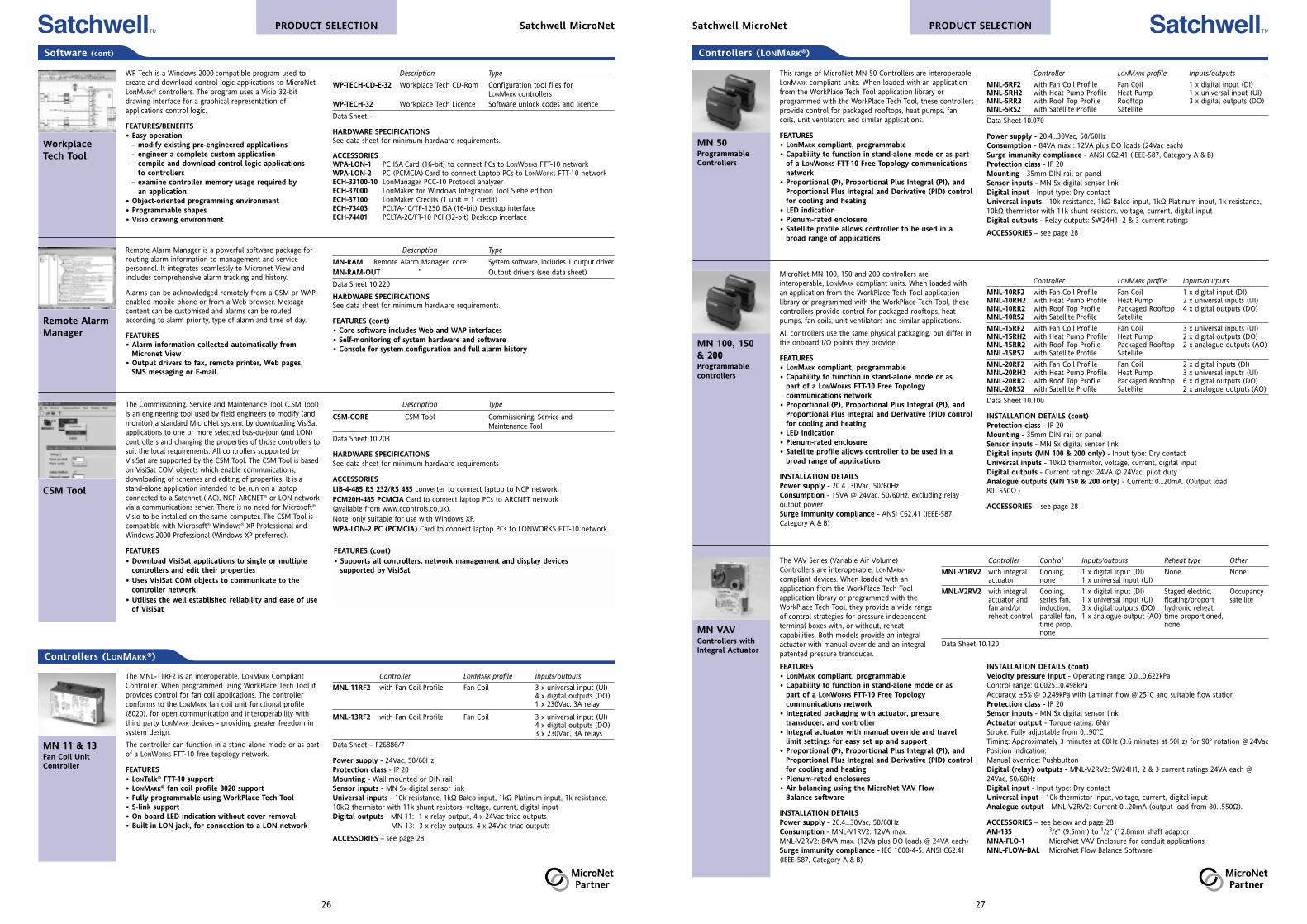
This range of MicroNet MN 50 Controllers are interoperable,LONMARK compliant units. When loaded with an applicationfrom the WorkPlace Tech Tool application library orprogrammed with the WorkPlace Tech Tool, these controllersprovide control for packaged rooftops, heat pumps, fancoils, unit ventilators and similar applications.
FEATURES• LONMARK compliant, programmable• Capability to function in stand-alone mode or as part
of a LONWORKS FTT-10 Free Topology communicationsnetwork
• Proportional (P), Proportional Plus Integral (PI), andProportional Plus Integral and Derivative (PID) controlfor cooling and heating
• LED indication• Plenum-rated enclosure• Satellite profile allows controller to be used in a
broad range of applications
MN 50ProgrammableControllers
Software (cont)
PRODUCT SELECTION Satchwell MicroNet
Description Type
WP-TECH-CD-E-32 Workplace Tech CD-Rom Configuration tool files for LONMARK controllers
WP-TECH-32 Workplace Tech Licence Software unlock codes and licence
Data Sheet –
HARDWARE SPECIFICATIONSSee data sheet for minimum hardware requirements.
ACCESSORIESWPA-LON-1 PC ISA Card (16-bit) to connect PCs to LONWORKS FTT-10 networkWPA-LON-2 PC (PCMCIA) Card to connect Laptop PCs to LONWORKS FTT-10 networkECH-33100-10 LonManager PCC-10 Protocol analyzerECH-37000 LonMaker for Windows Integration Tool Siebe editionECH-37100 LonMaker Credits (1 unit = 1 credit)ECH-73403 PCLTA-10/TP-1250 ISA (16-bit) Desktop interfaceECH-74401 PCLTA-20/FT-10 PCI (32-bit) Desktop interface
WP Tech is a Windows 2000 compatible program used tocreate and download control logic applications to MicroNetLONMARK® controllers. The program uses a Visio 32-bitdrawing interface for a graphical representation ofapplications control logic.
FEATURES/BENEFITS• Easy operation
– modify existing pre-engineered applications– engineer a complete custom application– compile and download control logic applications
to controllers– examine controller memory usage required by
an application• Object-oriented programming environment• Programmable shapes• Visio drawing environment
WorkplaceTech Tool
Description Type
MN-RAM Remote Alarm Manager, core System software, includes 1 output driverMN-RAM-OUT ” Output drivers (see data sheet)
Data Sheet 10.220
HARDWARE SPECIFICATIONSSee data sheet for minimum hardware requirements.
FEATURES (cont)• Core software includes Web and WAP interfaces• Self-monitoring of system hardware and software• Console for system configuration and full alarm history
Remote Alarm Manager is a powerful software package forrouting alarm information to management and servicepersonnel. It integrates seamlessly to Micronet View andincludes comprehensive alarm tracking and history.
Alarms can be acknowledged remotely from a GSM or WAP-enabled mobile phone or from a Web browser. Messagecontent can be customised and alarms can be routedaccording to alarm priority, type of alarm and time of day.
FEATURES• Alarm information collected automatically from
Micronet View• Output drivers to fax, remote printer, Web pages,
SMS messaging or E-mail.
Remote AlarmManager
26
Description Type
CSM-CORE CSM Tool Commissioning, Service andMaintenance Tool
Data Sheet 10.203
HARDWARE SPECIFICATIONSSee data sheet for minimum hardware requirements
ACCESSORIESLIB-4-485 RS 232/RS 485 converter to connect laptop to NCP network.PCM20H-485 PCMCIA Card to connect laptop PCs to ARCNET network(available from www.ccontrols.co.uk).Note: only suitable for use with Windows XP.WPA-LON-2 PC (PCMCIA) Card to connect laptop PCs to LONWORKS FTT-10 network.
The Commissioning, Service and Maintenance Tool (CSM Tool)is an engineering tool used by field engineers to modify (andmonitor) a standard MicroNet system, by downloading VisiSatapplications to one or more selected bus-du-jour (and LON)controllers and changing the properties of those controllers tosuit the local requirements. All controllers supported byVisiSat are supported by the CSM Tool. The CSM Tool is basedon VisiSat COM objects which enable communications,downloading of schemes and editing of properties. It is astand-alone application intended to be run on a laptopconnected to a Satchnet (IAC), NCP ARCNET® or LON networkvia a communications server. There is no need for Microsoft®
Visio to be installed on the same computer. The CSM Tool iscompatible with Microsoft® Windows® XP Professional andWindows 2000 Professional (Windows XP preferred).
FEATURES• Download VisiSat applications to single or multiple
controllers and edit their properties• Uses VisiSat COM objects to communicate to the
controller network• Utilises the well established reliability and ease of use
of VisiSat
CSM Tool
FEATURES (cont)• Supports all controllers, network management and display devices
supported by VisiSat
Controllers (LONMARK®)
Controller LONMARK profile Inputs/outputs
MNL-11RF2 with Fan Coil Profile Fan Coil 3 x universal input (UI)4 x digital outputs (DO)1 x 230Vac, 3A relay
MNL-13RF2 with Fan Coil Profile Fan Coil 3 x universal input (UI)4 x digital outputs (DO)3 x 230Vac, 3A relays
Data Sheet – F26886/7
Power supply - 24Vac, 50/60HzProtection class - IP 20 Mounting - Wall mounted or DIN railSensor inputs - MN Sx digital sensor linkUniversal inputs - 10k resistance, 1kΩ Balco input, 1kΩ Platinum input, 1k resistance,10kΩ thermistor with 11k shunt resistors, voltage, current, digital inputDigital outputs - MN 11: 1 x relay output, 4 x 24Vac triac outputs
MN 13: 3 x relay outputs, 4 x 24Vac triac outputs
ACCESSORIES – see page 28
The MNL-11RF2 is an interoperable, LONMARK CompliantController. When programmed using WorkPlace Tech Tool itprovides control for fan coil applications. The controllerconforms to the LONMARK fan coil unit functional profile(8020), for open communication and interoperability withthird party LONMARK devices - providing greater freedom insystem design.
The controller can function in a stand-alone mode or as partof a LONWORKS FTT-10 free topology network.
FEATURES• LONTalk® FTT-10 support• LONMARK® fan coil profile 8020 support• Fully programmable using WorkPlace Tech Tool• S-link support• On board LED indication without cover removal• Built-in LON jack, for connection to a LON network
MN 11 & 13Fan Coil UnitController
29
Controllers (Bus-du-jour®)
Controller Comms protocol Inputs/outputs
MNN-50-100 NCP NCP as standard 2 x digital inputsProgrammable ARCNET with plug-in card 10 x universal inputsController LONWORKS with plug-in card 6 x relay outputs
4 x analogue outputs
Data Sheet 10.103
INSTALLATION DETAILSPower supply - 24Vac, 50/60HzConsumption - 12VAProtection class - IP 40Mounting - Wall or 35mm DIN railInputs - 2 digital pulse counting inputs, 10 universal inputs (digital, resistive, 0...10Vdc)Outputs - 6 digital outputs (Line Relay) 5A resistive at 230Vac4 analogue outputs (0...10Vdc)Power failure reserve - Controller EEPROM preserves memory for 10 years undernormal conditions of use. The software clock will stop during a power failure. If thecontroller has an RTC card, then the time will not be lost.
ACCESSORIES – and see main section belowMN-DK Display Wall Mounting KitMN-LCD-100 MicroNet LCD DisplayMN-LCDP-100 MicroNet LCD Display (for panel mounting)MN-TK Trunking Mounting KitMNN-COM NCP Plug-in cardMNN-TS-100 MicroNet Touch NCP Screen DisplayMNN-TSP-100 MicroNet Touch NCP Screen Display (for panel mounting)
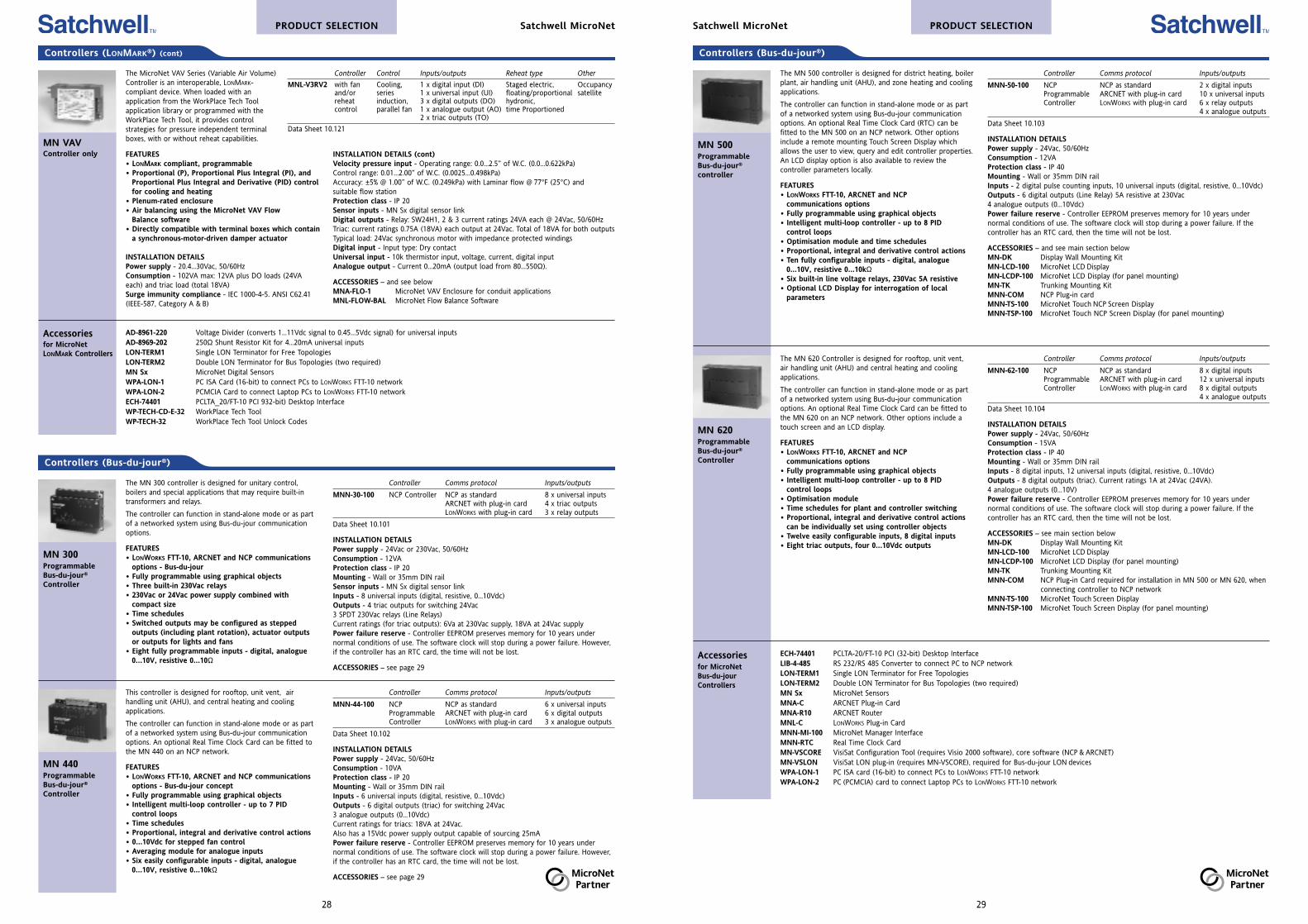
The MN 500 controller is designed for district heating, boilerplant, air handling unit (AHU), and zone heating and coolingapplications.
The controller can function in stand-alone mode or as partof a networked system using Bus-du-jour communicationoptions. An optional Real Time Clock Card (RTC) can befitted to the MN 500 on an NCP network. Other optionsinclude a remote mounting Touch Screen Display whichallows the user to view, query and edit controller properties.An LCD display option is also available to review thecontroller parameters locally.
FEATURES• LONWORKS FTT-10, ARCNET and NCP
communications options• Fully programmable using graphical objects• Intelligent multi-loop controller - up to 8 PID
control loops• Optimisation module and time schedules• Proportional, integral and derivative control actions• Ten fully configurable inputs - digital, analogue
0...10V, resistive 0...10kΩ• Six built-in line voltage relays, 230Vac 5A resistive• Optional LCD Display for interrogation of local
parameters
MN 500Programmable Bus-du-jour®
controller
PRODUCT SELECTIONSatchwell MicroNet
ECH-74401 PCLTA-20/FT-10 PCI (32-bit) Desktop InterfaceLIB-4-485 RS 232/RS 485 Converter to connect PC to NCP networkLON-TERM1 Single LON Terminator for Free TopologiesLON-TERM2 Double LON Terminator for Bus Topologies (two required)MN Sx MicroNet SensorsMNA-C ARCNET Plug-in CardMNA-R10 ARCNET RouterMNL-C LONWORKS Plug-in CardMNN-MI-100 MicroNet Manager InterfaceMNN-RTC Real Time Clock CardMN-VSCORE VisiSat Configuration Tool (requires Visio 2000 software), core software (NCP & ARCNET)MN-VSLON VisiSat LON plug-in (requires MN-VSCORE), required for Bus-du-jour LON devicesWPA-LON-1 PC ISA card (16-bit) to connect PCs to LONWORKS FTT-10 networkWPA-LON-2 PC (PCMCIA) card to connect Laptop PCs to LONWORKS FTT-10 network
Controller Comms protocol Inputs/outputs
MNN-62-100 NCP NCP as standard 8 x digital inputsProgrammable ARCNET with plug-in card 12 x universal inputsController LONWORKS with plug-in card 8 x digital outputs
4 x analogue outputs
Data Sheet 10.104
INSTALLATION DETAILSPower supply - 24Vac, 50/60HzConsumption - 15VAProtection class - IP 40Mounting - Wall or 35mm DIN railInputs - 8 digital inputs, 12 universal inputs (digital, resistive, 0...10Vdc)Outputs - 8 digital outputs (triac). Current ratings 1A at 24Vac (24VA).4 analogue outputs (0...10V)Power failure reserve - Controller EEPROM preserves memory for 10 years undernormal conditions of use. The software clock will stop during a power failure. If thecontroller has an RTC card, then the time will not be lost.
ACCESSORIES – see main section belowMN-DK Display Wall Mounting KitMN-LCD-100 MicroNet LCD DisplayMN-LCDP-100 MicroNet LCD Display (for panel mounting)MN-TK Trunking Mounting KitMNN-COM NCP Plug-in Card required for installation in MN 500 or MN 620, when
connecting controller to NCP networkMNN-TS-100 MicroNet Touch Screen DisplayMNN-TSP-100 MicroNet Touch Screen Display (for panel mounting)
The MN 620 Controller is designed for rooftop, unit vent,air handling unit (AHU) and central heating and coolingapplications.
The controller can function in stand-alone mode or as partof a networked system using Bus-du-jour communicationoptions. An optional Real Time Clock Card can be fitted tothe MN 620 on an NCP network. Other options include atouch screen and an LCD display.
FEATURES• LONWORKS FTT-10, ARCNET and NCP
communications options• Fully programmable using graphical objects• Intelligent multi-loop controller - up to 8 PID
control loops• Optimisation module• Time schedules for plant and controller switching• Proportional, integral and derivative control actions
can be individually set using controller objects• Twelve easily configurable inputs, 8 digital inputs• Eight triac outputs, four 0...10Vdc outputs
MN 620Programmable Bus-du-jour®
Controller
Accessoriesfor MicroNet Bus-du-jourControllers
28
AD-8961-220 Voltage Divider (converts 1...11Vdc signal to 0.45...5Vdc signal) for universal inputsAD-8969-202 250Ω Shunt Resistor Kit for 4...20mA universal inputsLON-TERM1 Single LON Terminator for Free TopologiesLON-TERM2 Double LON Terminator for Bus Topologies (two required)MN Sx MicroNet Digital SensorsWPA-LON-1 PC ISA Card (16-bit) to connect PCs to LONWORKS FTT-10 networkWPA-LON-2 PCMCIA Card to connect Laptop PCs to LONWORKS FTT-10 networkECH-74401 PCLTA_20/FT-10 PCI 932-bit) Desktop InterfaceWP-TECH-CD-E-32 WorkPlace Tech ToolWP-TECH-32 WorkPlace Tech Tool Unlock Codes
INSTALLATION DETAILS (cont)Velocity pressure input - Operating range: 0.0...2.5” of W.C. (0.0...0.622kPa)Control range: 0.01...2.00” of W.C. (0.0025...0.498kPa)Accuracy: ±5% @ 1.00” of W.C. (0.249kPa) with Laminar flow @ 77°F (25°C) andsuitable flow stationProtection class - IP 20 Sensor inputs - MN Sx digital sensor linkDigital outputs - Relay: SW24H1, 2 & 3 current ratings 24VA each @ 24Vac, 50/60HzTriac: current ratings 0.75A (18VA) each output at 24Vac. Total of 18VA for both outputsTypical load: 24Vac synchronous motor with impedance protected windingsDigital input - Input type: Dry contactUniversal input - 10k thermistor input, voltage, current, digital inputAnalogue output - Current 0...20mA (output load from 80...550Ω).
ACCESSORIES – and see belowMNA-FLO-1 MicroNet VAV Enclosure for conduit applicationsMNL-FLOW-BAL MicroNet Flow Balance Software
The MicroNet VAV Series (Variable Air Volume)Controller is an interoperable, LONMARK-compliant device. When loaded with anapplication from the WorkPlace Tech Toolapplication library or programmed with theWorkPlace Tech Tool, it provides controlstrategies for pressure independent terminalboxes, with or without reheat capabilities.MN VAV
Controller only
Controller Control Inputs/outputs Reheat type Other
MNL-V3RV2 with fan Cooling, 1 x digital input (DI) Staged electric, Occupancyand/or series 1 x universal input (UI) floating/proportional satellitereheat induction, 3 x digital outputs (DO) hydronic,control parallel fan 1 x analogue output (AO) time Proportioned
2 x triac outputs (TO)
Data Sheet 10.121
FEATURES• LONMARK compliant, programmable• Proportional (P), Proportional Plus Integral (PI), and
Proportional Plus Integral and Derivative (PID) controlfor cooling and heating
• Plenum-rated enclosure• Air balancing using the MicroNet VAV Flow
Balance software• Directly compatible with terminal boxes which contain
a synchronous-motor-driven damper actuator
INSTALLATION DETAILSPower supply - 20.4...30Vac, 50/60HzConsumption - 102VA max: 12VA plus DO loads (24VAeach) and triac load (total 18VA)Surge immunity compliance - IEC 1000-4-5. ANSI C62.41(IEEE-587, Category A & B)
Accessoriesfor MicroNetLONMARk Controllers
Controllers (LONMARK®) (cont)
PRODUCT SELECTION Satchwell MicroNet
Controllers (Bus-du-jour®)
Controller Comms protocol Inputs/outputs
MNN-30-100 NCP Controller NCP as standard 8 x universal inputsARCNET with plug-in card 4 x triac outputsLONWORKS with plug-in card 3 x relay outputs
Data Sheet 10.101
INSTALLATION DETAILSPower supply - 24Vac or 230Vac, 50/60HzConsumption - 12VAProtection class - IP 20Mounting - Wall or 35mm DIN railSensor inputs - MN Sx digital sensor linkInputs - 8 universal inputs (digital, resistive, 0...10Vdc)Outputs - 4 triac outputs for switching 24Vac3 SPDT 230Vac relays (Line Relays)Current ratings (for triac outputs): 6Va at 230Vac supply, 18VA at 24Vac supplyPower failure reserve - Controller EEPROM preserves memory for 10 years undernormal conditions of use. The software clock will stop during a power failure. However,if the controller has an RTC card, the time will not be lost.
ACCESSORIES – see page 29
The MN 300 controller is designed for unitary control,boilers and special applications that may require built-intransformers and relays.
The controller can function in stand-alone mode or as partof a networked system using Bus-du-jour communicationoptions.
FEATURES• LONWORKS FTT-10, ARCNET and NCP communications
options - Bus-du-jour• Fully programmable using graphical objects• Three built-in 230Vac relays• 230Vac or 24Vac power supply combined with
compact size• Time schedules• Switched outputs may be configured as stepped
outputs (including plant rotation), actuator outputsor outputs for lights and fans
• Eight fully programmable inputs - digital, analogue0...10V, resistive 0...10Ω
MN 300Programmable Bus-du-jour®
Controller
Controller Comms protocol Inputs/outputs
MNN-44-100 NCP NCP as standard 6 x universal inputsProgrammable ARCNET with plug-in card 6 x digital outputsController LONWORKS with plug-in card 3 x analogue outputs
Data Sheet 10.102
INSTALLATION DETAILSPower supply - 24Vac, 50/60HzConsumption - 10VAProtection class - IP 20Mounting - Wall or 35mm DIN railInputs - 6 universal inputs (digital, resistive, 0...10Vdc)Outputs - 6 digital outputs (triac) for switching 24Vac3 analogue outputs (0...10Vdc)Current ratings for triacs: 18VA at 24Vac. Also has a 15Vdc power supply output capable of sourcing 25mAPower failure reserve - Controller EEPROM preserves memory for 10 years undernormal conditions of use. The software clock will stop during a power failure. However,if the controller has an RTC card, the time will not be lost.
ACCESSORIES – see page 29
This controller is designed for rooftop, unit vent, airhandling unit (AHU), and central heating and coolingapplications.
The controller can function in stand-alone mode or as partof a networked system using Bus-du-jour communicationoptions. An optional Real Time Clock Card can be fitted tothe MN 440 on an NCP network.
FEATURES• LONWORKS FTT-10, ARCNET and NCP communications
options - Bus-du-jour concept• Fully programmable using graphical objects• Intelligent multi-loop controller - up to 7 PID
control loops• Time schedules• Proportional, integral and derivative control actions• 0...10Vdc for stepped fan control• Averaging module for analogue inputs• Six easily configurable inputs - digital, analogue
0...10V, resistive 0...10kΩ
MN 440Programmable Bus-du-jour®
Controller
Controllers Type Inputs/outputs
Bonsai Pro 230VacBRC-41N-10X with on/off fan control (networkable) 2 x DIBRC-51N-10X with 3-speed fan control (networkable) 1 x DI – temperatureBonsai Lite 24Vac 1 x AI – setpointBRC-41N-50X with on/off fan control (stand-alone) 1 x DO – triacs (-41N- only)BRC-51N-50X with 3-speed fan control (stand-alone) 3 x DO – relays (-51N- only)Where X denotes the pre-loaded application 2 x Bonsai outputs(possible to change on the field)0 = 4-pipe FCU, 1 = 2-pipe with changeover
URC-IR-100 Infra-red/RS 232 receiverURC-SET-100 NCP Palm/Expert commissioning software
Data Sheet 4.102 & 4.103
INSTALLATION DETAILSControl range - 0...40°CControl algorithm - Proportional + integral (time adjustable), or proportional onlyPower supply - 230Vac (+10%...–6%) Bonsai Pro, 24Vac (+10%...–6%) Bonsai Lite Power failure reserve - E2PROM preserves configuration data and user settingsTriac for heater battery - 24Vac output, 2.4VA maxRelay outputs - 230Vac, 5A resistiveNetwork interface - RS 485 to Sigma or MicroNet network (-10X only)Sensor types - DU 4301, DUS 4302 or DDU 0001 (return air), MN-S1, S2, S3, S4Controller protection class - IP 10Mounting - Wall mounting or DIN rail mounting
ACCESSORIES BCA 1601 – Controller enclosure for field mountingBCA 1602 – Controller set-point adjustment module (±3°C)BCA 9202 – Spare fuses (packet of 5)
VALVE/ACTUATORS Size/Kvs Loop compatible with:
BFB 1500 15mm – 1.6, 2.0, 2.5 Kvs * Bonsai BRC ControllerBFB 1501 15mm – 0.6, 1.0 Kvs *BFB 1506 15mm – 0.6 Kvs
BFB 1510 15mm – 1.0 Kvs
BFB 1516 15mm – 1.6 Kvs
BFB 1520 15mm – 2.0 Kvs
BFB 1525 15mm – 2.5 Kvs
Data Sheet 4.102
Kvs = Flow in m3 to produce a 1 bar pressure drop when the valve is fully open.* Kvs is determined by a selectable Kv clip.
INSTALLATION DETAILSProtection class - IP 52Control medium - water or glycol solution in water (25% max, freeze protection)Temperature Limits - 2...95°CBypass Kvs - 70% of rated KvsInternational Pressure Rating - PN 10Type of Operation - RotaryActuator Protection Class - IP 52Cable - 3 core fly lead with controller connection, length 1.5mManual Override - By rotary movement of valve armPosition Indication - Reference moving part to actuator body
ACCESSORIES BSA 1501 – 1m extension lead (one per actuator)
Bonsai Pro &Bonsai LiteFan Coil ControlLoop
Bonsai is a revolutionary new Fan Coil Control Loop thatoffers incredible performance and features. The loop isconfigurable to suit your applications by offering the latesttechnology and variable options.
Select from a choice of controllers, valves and sensors tobuild your control loop. The control loop can beprogrammed locally and can be connected to Sigma orMicroNet if required (Bonsai Pro only). Alternatively it canbe left to function stand-alone (Bonsai Lite). The controllermeets the latest CEN application requirements and offerslow cost engineering without maintenance. The patentedvalve design ensures long trouble free life
FEATURES
Valves• Patented Fluid Control Methodology• 3 main valve parts ensures reliable operation• Ultra low torque valve requirement/Low to silent
operation• High speed of response• Dramatically reduces the chances of valve blockage• No user maintenance required• 'Tool free' manual override• Position indication• Variable Kv allows large range of applications• Modified equal percentage characteristic• 1.5m fly lead• IP 52 (actuator)• Market leading technology• Accurate performance across full ambient
temperature range• Coil balancing bypass as standard• High differential pressure• Simple installation and commissioning
Controllers• Fully networkable or stand-alone controllers• Easy upgrade of old systems• High resolution control• Simple connection to controller• Controller tests and simulates operation to reduce
commissioning times• Controller has built in maintenance cycles• Automated installation and commissioning• Selectable control applications (fan-coil applications)• Low installation cost• Simple setup using PDA hand-held computer or PC via
infra-red or RS 232 link• Designed to maximise energy savings• Optional networking to an MicroNet system
31
Controller type Inputs/outputs
URC-41N-10X with on/off fan control and S-link support 2 x DIURC-51N-10X with 3-speed fan control and S-link support 1 x RI – temperature
1 x AI – setpointWhere X denotes the pre-loaded application 4 x DO – triacs(possible to change on the field) 3 x DO – relays0 = 4-pipe FCU, 1 = 2-pipe with changeover,2 = DX cooling and electric heater, 3 = airside control
URC-IR-100 Infra-red/RS 232 ReceiverURC-SET-100 NCP Palm Commissioning Software
Data Sheet 10.130
INSTALLATION DETAILSControl range - 0...40°CPower supply - 230Vac (+10%...–6%)Power failure reserve - E2PROM preserves configuration data and user settingsSensor types - DU 4301, DUS 4302, S1, S2, S3, S4 (room) or DDU 0001 (return air) Protection class - IP 20Mounting - Wall mounting or DIN rail mounting
UniFact® ProTerminal UnitControllers
The UNIFACTPRO Terminal Unit Controllers have beendesigned to meet virtually any fan-coil heating/coolingapplications. The controllers can be used as stand-alonedevices or can be networked to MicroNet systems.
The controller has three main modes: comfort (day), night(off) and economy. The controller can be switched into anyof these three modes from the MicroNet View PC (if used).When used stand-alone, the controller can be switchedbetween two modes: either comfort and economy, orcomfort and night, as selected during commissioning.A voltage-free input (a timer switch, digital room sensoror PIR) can be used to switch between the two modes.A second voltage-free digital input is available forconnection to a thermostat for automatic changeoverbetween cooling and heating modes for 2-pipe fan coil unit(FCU) applications.
FEATURES• Fully networkable or stand-alone controllers• Selectable control applications (fan-coil applications)• Low installation cost• Simple setup using PDA hand-held computer or PC via
infra-red or RS 232 link• Designed to maximise energy savings• Optional networking to an MicroNet system
PRODUCT SELECTIONSatchwell MicroNet
Fan Coil Unit Solutions (cont)
Fan Coil Unit Solutions
30
PRODUCT SELECTION Satchwell MicroNet
Function/associated products Controllers
Networkable Standalone
2-pipe 2-pipe auto changeover 4-pipe
Air side control (4-pipe) Actuator slaving Sensor slaving
Fan on/off Fan 3-speed control
On board transformer On board relays 1 1 1 1 3 3 3 3 1 1 3 3 1 1 3 3 1 3
Output for electric heater DX cooling
Room sensors DRT DU DUS S1 (S-Link) S2 ” S3 ” S4 ” S4-FCS ”
Duct sensors DDU DDT
Actuator/valves AVU AVX BFB (Bonsai)
See page 37 31 31 26
CZU
420
1
URC-4
1N-1
00
URC-4
1N-1
01
URC-4
1N-1
02
URC-4
1N-1
03
URC-5
1N-1
00
URC-5
1N-1
01
URC-5
1N-1
02
URC-5
1N-1
03
BRC-4
1N-1
00
BRC-4
1N-1
01
BRC-5
1N-1
00
BRC-5
1N-1
01
BRC-4
1N-5
00
BRC-4
1N-5
01
BRC-5
1N-5
00
BRC-5
1N-5
01
MN
L-11
RF2
MN
L-13
RF2
Digital Modules
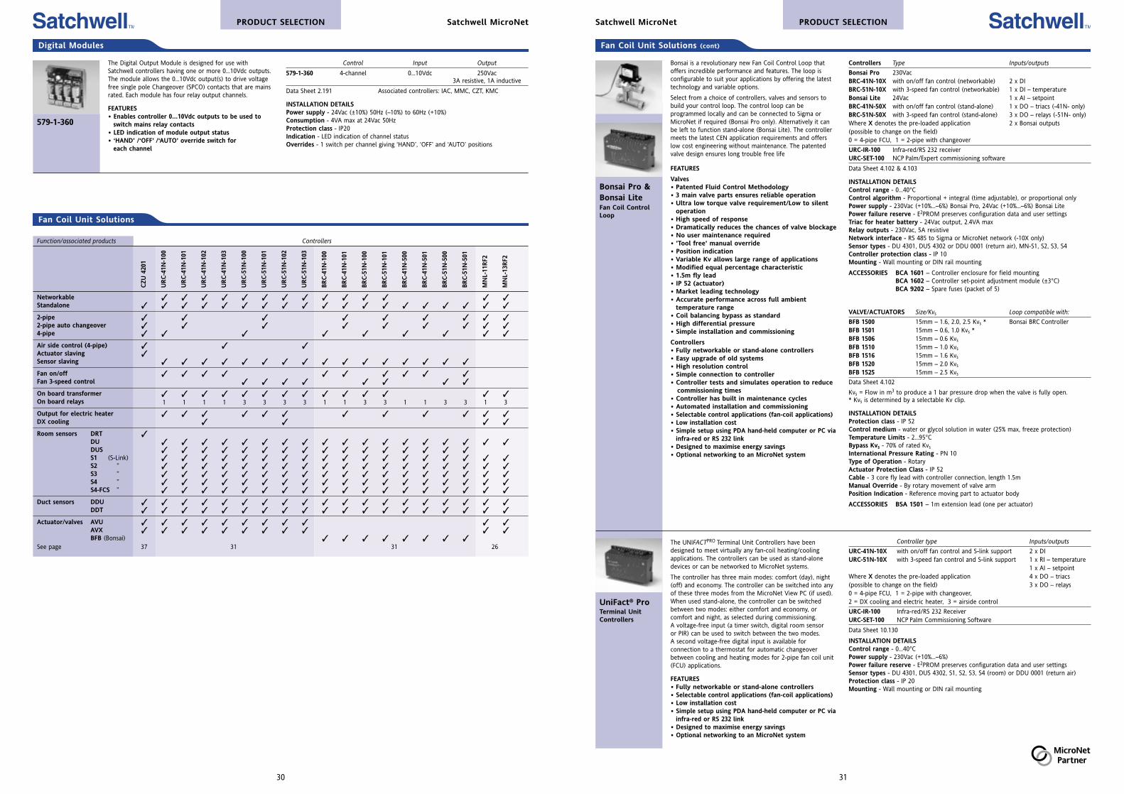
The Digital Output Module is designed for use withSatchwell controllers having one or more 0...10Vdc outputs.The module allows the 0...10Vdc output(s) to drive voltagefree single pole Changeover (SPCO) contacts that are mainsrated. Each module has four relay output channels.
FEATURES• Enables controller 0...10Vdc outputs to be used to
switch mains relay contacts• LED indication of module output status• ‘HAND’ /‘OFF’ /‘AUTO’ override switch for
each channel
579-1-360
Control Input Output
579-1-360 4-channel 0...10Vdc 250Vac3A resistive, 1A inductive
Data Sheet 2.191 Associated controllers: IAC, MMC, CZT, KMC
INSTALLATION DETAILSPower supply - 24Vac (±10%) 50Hz (–10%) to 60Hz (+10%)Consumption - 4VA max at 24Vac 50HzProtection class - IP20Indication - LED indication of channel statusOverrides - 1 switch per channel giving ‘HAND’, ‘OFF’ and ‘AUTO’ positions
33
PRODUCT SELECTIONSatchwell MicroNet
MicroNet System components can only beinstalled and commissioned by qualifiedMicroNet Partner engineers.
Sensors
Description Keypad Display
MN-S1 Sensor only none none
MN-S2 Sensor with override 1 button LED override status indication
MN-S3 Sensor with setpoint adjustment 2 buttons LCD and LED overrideand override status indication
MN-S4 Sensor with setpoint, override 5 buttons LCD and LED overrideand controller mode functions status indication
MN-S4-FCS Sensor with setpoint, on/off 5 buttons LCD and LED fanand fan speed functions status indication
MN-S5 Sensor with setpoint, override 6 buttons LCD and LED overridecontroller mode functions and status indicationemergency heat key/indication
Data Sheet 10.000
INSTALLATION DETAILSPower supply - Powered from the controllerProtection class - IP 20Ambient limits - Operating temperature 0...50°C, humidity 5...95% rh, non-condensing
The MicroNet Sensors MN Sx Series are a family of digitalwall temperature sensors for use with I/A Series MicroNetControllers. These sensors feature a Sensor Link (S-LK)communication protocol which provides a simple two-wireinterface for power and exchange of sensor and subbaseinformation. Subbase information includes selecting set-point, fan speed, operating mode, or emergency heat.Available in six models, MicroNet Sensors provide an integralanalogue-to-digital conversion for elimination of sensor-to-controller noise effects and wire resistance offset.
FEATURES• Aesthetically styled, low profile packaging• Digital zone temperature indication with variable
resolution and unit of measure• Self-compensating temperature conversions remove
the need for periodic calibration• Override button allows the user to switch to operation
mode for out of hours occupation• Displays selected system values such as setpoint,
external air temperature and operating mode• Enables the alteration of operating modes
MN SxDigital TemperatureSensors
Adjustable Sensing Fan speed Switch scale range override function
DU 4301 none –5...+50°C – –
DUS 4302 +/– –5...+50°C – –
DUSF 4351 +/– –5...+50°C • Auto, off, on
DUSF 4352 +/– –5...+50°C • Auto, off, 1, 2, 3
Data Sheet 1.020 Associated controllers: MN 200/440/500/620 (DU & DUS only URC)
INSTALLATION DETAILSSensing element - Negative temp. coefficient thermistorWiring - Low voltage dc (15Vdc), DU 3 wire, DUS 4 wire, DUSF 7 wire Power supply - 15Vdc from UniFact controller
ACCESSORY 837-1-203 Guard Kit
These sensors are specifically used for Satchwell controllers.Models types have light that informs you that the controlleris running. All sensors use the same single gang sized case.
FEATURES• Small physical size• Attractive case design and neutral colour fits in with
most room designs• Extra low voltage on all sensor types including fan
speed control versions• Simple wiring connections• Simple commissioning• Controller running power light on the sensor
DU, DUSDUSFMicroNet Sensors
Interfaces
Controller Comms protocol Number of devices
MNN-MI-100 MicroNet NCP as standard 20 x 61 max (per network)NCP Interface ARCNET with plug-in card 31 x 94 max (per network
Data Sheet 10.210A
INSTALLATION DETAILSMounting - Panel or DIN railPower supply - 24VacProtection class - IP 40
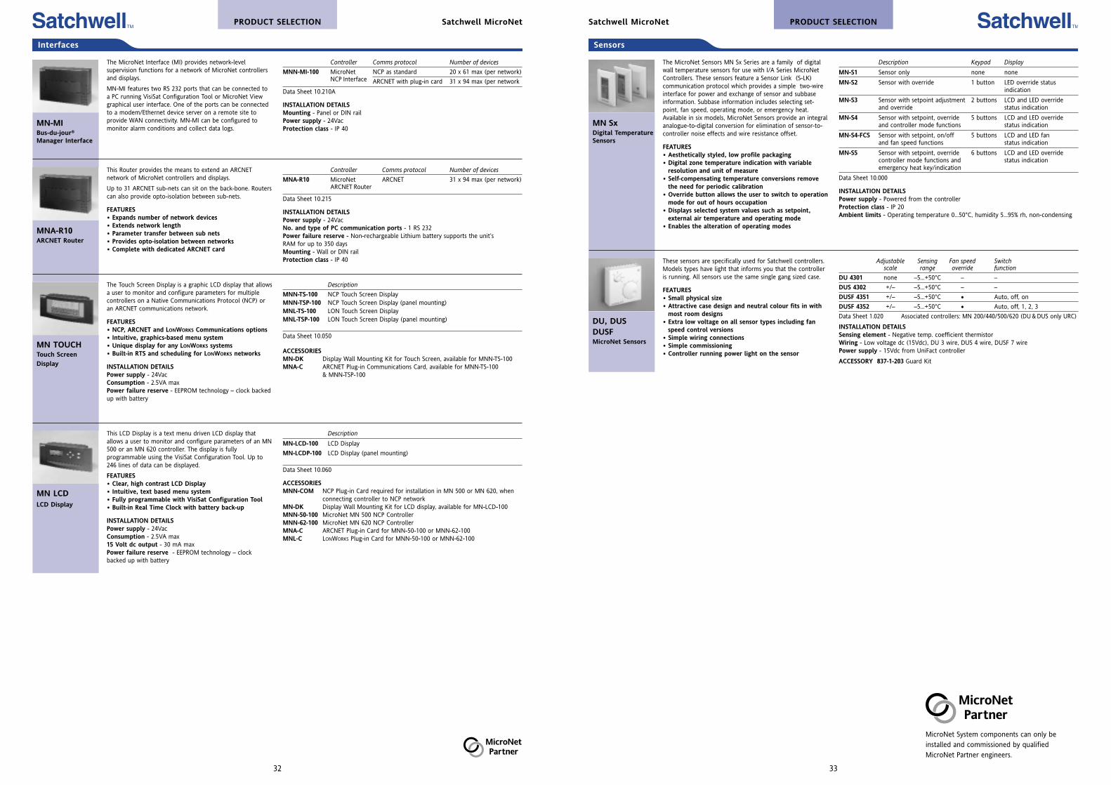
The MicroNet Interface (MI) provides network-levelsupervision functions for a network of MicroNet controllersand displays.
MN-MI features two RS 232 ports that can be connected toa PC running VisiSat Configuration Tool or MicroNet Viewgraphical user interface. One of the ports can be connectedto a modem/Ethernet device server on a remote site toprovide WAN connectivity. MN-MI can be configured tomonitor alarm conditions and collect data logs.
MN-MIBus-du-jour®
Manager Interface
Controller Comms protocol Number of devices
MNA-R10 MicroNet ARCNET 31 x 94 max (per network)ARCNET Router
Data Sheet 10.215
INSTALLATION DETAILSPower supply - 24VacNo. and type of PC communication ports - 1 RS 232Power failure reserve - Non-rechargeable Lithium battery supports the unit’sRAM for up to 350 daysMounting - Wall or DIN railProtection class - IP 40
This Router provides the means to extend an ARCNETnetwork of MicroNet controllers and displays.
Up to 31 ARCNET sub-nets can sit on the back-bone. Routerscan also provide opto-isolation between sub-nets.
FEATURES• Expands number of network devices• Extends network length• Parameter transfer between sub nets• Provides opto-isolation between networks• Complete with dedicated ARCNET card
MNA-R10ARCNET Router
The Touch Screen Display is a graphic LCD display that allowsa user to monitor and configure parameters for multiplecontrollers on a Native Communications Protocol (NCP) oran ARCNET communications network.
FEATURES• NCP, ARCNET and LONWORKS Communications options• Intuitive, graphics-based menu system• Unique display for any LONWORKS systems• Built-in RTS and scheduling for LONWORKS networks
INSTALLATION DETAILSPower supply - 24VacConsumption - 2.5VA maxPower failure reserve - EEPROM technology – clock backedup with battery
MN TOUCHTouch Screen
Display
Description
MN-LCD-100 LCD Display
MN-LCDP-100 LCD Display (panel mounting)
Data Sheet 10.060
ACCESSORIESMNN-COM NCP Plug-in Card required for installation in MN 500 or MN 620, when
connecting controller to NCP networkMN-DK Display Wall Mounting Kit for LCD display, available for MN-LCD-100MNN-50-100 MicroNet MN 500 NCP ControllerMNN-62-100 MicroNet MN 620 NCP ControllerMNA-C ARCNET Plug-in Card for MNN-50-100 or MNN-62-100MNL-C LONWORKS Plug-in Card for MNN-50-100 or MNN-62-100
This LCD Display is a text menu driven LCD display thatallows a user to monitor and configure parameters of an MN500 or an MN 620 controller. The display is fullyprogrammable using the VisiSat Configuration Tool. Up to246 lines of data can be displayed.
FEATURES• Clear, high contrast LCD Display• Intuitive, text based menu system• Fully programmable with VisiSat Configuration Tool• Built-in Real Time Clock with battery back-up
INSTALLATION DETAILSPower supply - 24VacConsumption - 2.5VA max15 Volt dc output - 30 mA max Power failure reserve - EEPROM technology – clockbacked up with battery
MN LCDLCD Display
Description
MNN-TS-100 NCP Touch Screen DisplayMNN-TSP-100 NCP Touch Screen Display (panel mounting)MNL-TS-100 LON Touch Screen DisplayMNL-TSP-100 LON Touch Screen Display (panel mounting)
Data Sheet 10.050
ACCESSORIESMN-DK Display Wall Mounting Kit for Touch Screen, available for MNN-TS-100MNA-C ARCNET Plug-in Communications Card, available for MNN-TS-100
& MNN-TSP-100
PRODUCT SELECTION Satchwell MicroNet
32
Optimiser
This Fuel-saving Controller can replace a conventional timeswitch on a heating system and provides a variable starttime dependent on the fall of room temperature during theoff period.
It is used to switch on and off central heating systems andwill substantially reduce fuel consumption compared withfixed time starting. In all but the very coldest weather thestart time is delayed until the latest time consistent with theamount of heat necessary to regain the requiredtemperature at occupancy time.
FEATURES• Easy installation - only one sensor required (packed
with the controller)• Programme override switch• Choice of day control by separate compensator or
built-in on/off day control• Minimum night ‘inside’ temperature protection• Analogue and Digital clock versions available
SVT7-day Optimiser
Version Output relays
SVT 4201 Analogue clock Plant, 250V, 2A (1A inductive)
SVT 4251 Digital clock Control, 250V, 2A (1A inductive)
Data Sheet 2.001
Compatible room sensor: DR 3253 (supplied with controller)
INSTALLATION DETAILSPower supply - 230V 50/60HzPower failure reserve - For clock - 100 hours, 2 hours for a short power interruptionProtection class - IP 41
PRODUCT SELECTIONSatchwell Controllers
35
CSC Compensators are designed for use in residential/commercial radiator systems to control either a three portmixing valve or a boiler. The controller senses outsidetemperature and varies the water flow temperature to theradiators. As the outside temperature falls, the radiatortemperature is increased.
An optional room temperature sensor can be used to trimthe water temperature based on room temperature. The CSCcan average up to four room sensors.
FEATURES• Easy to install and commission• Shipped with typical default values• Operates a three port valve or boiler• Max. return function for District Heating applications• Adjustable economy function• Night Set Back (NSB) and set-up/boost inputs• Flow high limit feature• User configurable Day/Night plant operation• Room influence mode selection• Cost effective upgrade of all obsolete Climatronic
controllers
CSCCompensatorControllers
Control Output
CSC 5252 Mains or 24V output with no clock Valve or boiler, 24Vac or 230Vac
CSC 5352 Mains or 24V output with clock Valve or boiler, 24vac or 230Vac, Pump triac, 24Vac, 1A maximum
Data Sheet 2.021
INSTALLATION DETAILSPower supply - 230Vac (+10%, –6%) 50/60HzPower failure reserve - Settings stored in memory, 1 year battery for clockProtection class - IP 30Switched inputs - Night Set Back (NSB): Voltage free, make/break contacts.Normally closed.Set Up (Boost): Voltage free, make/break contacts. Normally closed.Outputs - Valve actuator or boiler output relays: 2 x single pole ON/OFF (interlocked)230Vac, 10A resistive, 6A inductive.Pump Output: 1 x 24Vac triac, 1A (0V switched). Clock version only.Output Supply: 2 x 24Vac terminals used to power external devices up to a total of10VA maximum.Sensor inputs - ‘T’ type sensorsSensor types - DRT 3453, 3451 (optional), DWT 0001, DST 0001, DOT 0002 (see table below)
Compensators
Control Output
CXR 5805 Single, two or three stage 24V actuator control
Data Sheet 2.110
INSTALLATION DETAILSPower supply - 230Vac (+10%, –6%) 50/60HzPower failure reserve - settings stored in memory, 1 year battery for clockProtection class - IP 30Switched inputs - Night Set Back (NSB): Voltage free, make/break contacts.Normally closed.Set Up: Voltage free, make/break contacts. Normally closed.Remote Low Limit (Summer): Voltage free, make/break contacts. Normally closed.Night Sensor Selection: Voltage free, make/break contacts. Normally closed.Outputs - Valve Actuator Output Triacs: 2 x 24Vac triacs, 1A (0V switched andsoftware interlocked).Output Supply: 2 x 24Vac terminals used to power the actuator up to a total of10VA maximum.Sensor inputs - ‘T’ type sensorsSensor types - DRT 3651, 3453, DDT 0001, DWT 0001, DST 0001, RPW 4425 (see tablebelow)
The CXR Controller is used to control room temperature byresetting the supply duct air temperature. The room sensorresets the duct supply temperature to achieve the desiredroom temperature. The room temperature can be sensed inthe room or extract duct. The supply duct loop has a purelyproportional control action with the room reset being aproportional plus integral control action.
FEATURES• Easy to install and commission• Shipped with typical default values• Quick set mode allows basic settings to be easily
checked and set• Simple override switch• Night Set Back (NSB), set-up, summer and night
sensor selection switched inputs• Optional Scandinavian night sensor• Up to 4 room sensors can be used for average room
temperature• Remote setting input for room set value (RPW)• Cost effective upgrade of all obsolete Climatronic
controllers
CXRAHU Room ResetController
Main Plant Controllers
SENSORS AND REMOTE SETTING UNITType Range
DRT 3651, 3453, 3451 Room –5...+40°C
DDT 0001 Duct –5...+100°C
DWT 0001 Water –10...+120°C
DST 0001 Water (strap on) 5...120°C
DOT 0002 Outside –40...+55°C
RPW 4425 Remote Set Value 5...50°C
RB1, RB2Relay Units
No. of switches Contact rating Suitable for:
RB1 2 x DPCO 230V, 6A resistive General purpose
RB2 3 x DPCO 230V, 6A resistive Valve/actuator
Data Sheet 21.685
INSTALLATION DETAILSPower supply - 230V ac, 45/60 HzAmbient limits - –18...66°C
Drayton relay units will operate over a wide range ofambient temperatures and are especially suited to heatingand ventilating installations where they might be mounted inclose proximity to boilers and other heat emitters.
FEATURES• Enclosed and easy to mount• Hassle free (time saving)• Simple design
04 03 109(RSU)Remote SwitchUnit
04 03 109 For use with DC 1100 controllers only
Data Sheet 2.043
This mode switch gives an easy means of overriding theDC1100 controller. The remote switch has four settings –Auto, Summer, Heating On and Holiday.
FEATURES• User friendly• Clearly labelled• Positive feel switch reduces ambiguity of position
Relay & Switching Units
Controllers
34
PRODUCT SELECTION Drayton Range
DC1100DC1100C*Self ConfiguringOptimiser/Compensator
* for replacementpurposes only
Networkable Range Inputs Output relay
DC1100 No –20...+120°C 6 x temperature sensors, 230V, 1A inductive
DC1100C Yes 1 x remote switch unit (SPNO)(auto/summer/heating on/holiday)
Data Sheet 2.042
Associated sensors - A701 (space), A702 (outdoor), A703 (immersion),A704 (strap-on), A705 (duct)
INSTALLATION DETAILSPower supply - 230Vac, 50/60 HzProtection class - IP 40
ACCESSORIES04 03 109 (RSU) Remote Switch UnitRB1 Interface Relay
FEATURES (cont)• Day economy• Pump run on• Alarms on low temperatures, controller and sensor faults• Pump and valve exerciser• Space temperature influence of compensator
The DC1100 is a stand-alone Direct Digital Controller, whichhas been designed to suit the control needs of the smallercommercial and larger domestic property.
It will control one or two boilers, with requirements foroptimum start and with direct or valve compensation.
A separate channel is provided for the control of hot water.
Each of the control routines can be used independently orcombined. In effect the unit can be a compensator, anoptimiser or a combined unit.
LEDs provide an immediate visual indication of output status.
FEATURES• Controller can be a combined or stand-alone
optimiser or compensator• One or two boiler control• Self learning compensator or fully settable• Self configuring or settable• Optimum start- and stop-self learning• Valve and boiler compensated flow• Hot water timed channel• Remote input (Auto/Summer/On/Holiday)• Frost protection – Multi stage
A70–Room, Outside,Immersion, Ductand SurfaceSensors
Type Sensing range Associated controllers
A701 Room (Iss E) 0...45°C DC RangeA702 Outside (Iss E) 0...120°C ”A703 Immersion (Iss D) 0...120°C ”A704 Surface (strap on) (Iss J) 0...120°C ”A705 Duct (Iss F) 0...120°C ”Data Sheet 1.955
INSTALLATION DETAILSSensoring element - Negative temp. coefficient thermistorWiring - 2 wire non-polarised low voltage dcAdjustments - ConcealedProtection class - IP 40 (space), IP 55 other types
The wide range of temperature sensors is designedspecifically for use with Theta, and DC controllers andprovides a selection suitable for most HVAC applications.
In addition to the regular sensors, there are also rangevariants and special limit sensors.
The space sensors are mounted in attractive white plastichousings to complement any decor. All other types arehoused in sturdy diecast units with mounting arrangementssuitable for their duties.
Sensors
Keyboard
Control Range Output Power Supply
MMC 4701 PID –40…+150°C 3 x 0...10Vdc 24vac0…100% rh 2 x 24V digital
Data Sheet 2.701
FEATURES• Serial link• Can be programmed through its own keyboard• Low voltage (24Vac)• Proportional + Integral + Derivative control action for stable control
without offset• Eleven applications to deal with most humidity and temperature
control schemes• Built-in real time clock and time schedule
INSTALLATION DETAILSPower failure reserve - Settings stored in memory for 1 year, 5 year batteryInputs - Sensors: DRT, DDT, DOT, DRH, DDH, DOW, DOS, DWTOutputs - Actuators: ALi, ALE, ALES, AVUE24Vac switched outputs: 2 x digital outputs, ALX, ALXS, ARXProtection class - IP 40 when flush mounted
This PID Controller can be used to control humidity ortemperature in various ventilation and air conditioningsystem applications.
The serial link function allows the MMC to be fullyintegrated into a networking system with all the advantagesof remote monitoring, alarms, logging, graphics and remotesetting of all control parameters. The MMC can work as afully stand-alone controller.
The controller can be configured to run in one of theapplications by simply selecting that application number.1. Single Stage Temperature Controller2. Two Stage Temperature Controller3. Three Stage Temperature Controller4. Three Stage Room Temperature Reset Controller with
Heat Recovery5. Three Stage Cascade Temperature Controller6. Single Stage Temperature Controller
(24Vac Actuator Output)7. Single Stage Humidity Controller8. Two Stage Humidity Controller9. Simple Single Stage Temperature Controller10. Simple Two Stage Temperature Controller11. Simple Three Stage Temperature Controller
MMC 4701Universal AirHandling UnitController
Control Range Output Power Supply
MMC 4601 Multi-loop –40…+150°C 2 x 0...10Vdc 24Vac2 x 24V digital
Data Sheet 2.751
FEATURES (cont)• Fast response time ensures suitability for tap water control• Compensation curve can have up to three programmable points giving the
curve two calculated ratios• Supply high limit• Built-in ‘default programme’ of typical settings for every parameter operates
on initial start-up• 0...10Vdc control outputs• PID programmable control loops • Periodic pump cycling • Frost protection logic
INSTALLATION DETAILSPower failure reserve - Settings stored in memory for 1 year, 5 year batteryInputs - Global sensorsOutputs - Actuators: ALi, ALE, ALES, AVUE24Vac switched outputs: 2 x digital outputsProtection class - IP 40 when flush mounted
The MMC is a Multi-loop Controller for use in districtheating schemes.
The controller incorporates three separate control loops, twocompensated and the other a constant temperature loop.
Up to 3 specific points are programmed for thecompensation graph. The MMC automatically joins up thesepoints to produce a user defined compensation curve. Thisadjusts and calculates the required set value of the supplytemperature to the compensated system to match theprevailing requirements.
The MMC has a self tuning function that allows each of the3 control loops to have its proportional band, integral actionand derivative action values automatically tuned. Self tuningcan be carried out from the MMC keyboard or fromoptional external momentary switches connected to it. Selftuning maximises the efficiency of control loop operation.
FEATURES• Serial link• Can be programmed through its own keyboard• Real Time Clock (RTC)• Self tuning for each control loop, maximises efficiency
for each loop
MMC 4601Multi-loop DistrictHeating Controller
PRODUCT SELECTIONSatchwell Controllers
37
Control Range Output
CZU 4201 2-stage heating and 10...40°C 24V actuator controlcooling with dead zone
Data Sheet 2.201
INSTALLATION DETAILSPower supply - 24Vac (±10%) 50/60HzProtection class - IP 20Override inputs - TSM 1501: Pipe surface thermostatAdjustments - Set Value: 10…40°C, Proportion Band: 0…3°K per stageDead Zone: 0…6°K, Actuator Stroke Setting: 12.5…75mmSensor inputs
Type Range
DRT 3451, 3453, 3801, 3851 Room –5...+40°C
DDT 0001 Duct –5...+100°C
DDU 0001, 1803 Duct –5...+40°C
Terminal Unit
The CZU is an Electronic Modulating Controller for thecontrol of terminal units or fan coils in air conditioningsystems serving small zones of buildings such as individualoffices and hotel bedrooms.
The range includes temperature sensors and actuatorsfor valve operation and associated two, three and fourport valves.
FEATURES• Simple installation• Three wire connection to actuators• Optional auto changeover• Minimal commissioning time
CZUFan Coil UnitController
36
Control Output
CXT 5605 Single or two stage 24V actuator control
Data Sheet 2.101
INSTALLATION DETAILSPower supply - 230Vac (+10%, –6%) 50/60HzPower failure reserve - Settings stored in memory, 1 year battery for clockProtection class - IP 30Switched inputs - Night Set Back (NSB): Voltage free, make/break contacts.Normally closed.Set Up: Voltage free, make/break contacts. Normally closed.Outputs - Valve Actuator Output Triacs: 2 x 24Vac triacs, 1A (0V switched and softwareinterlocked).Output Supply: 2 x 24Vac terminals used to power the actuator up to a total of10VA maximum.Sensor inputs - ‘T’ type sensorsSensor types - DDT 0001, DWT 0001, DST 0001, RPW 4425 (see table on previous page)
The CXT Controller is primarily designed to control systemswith short time constants and fast response times. Thiswould typically be the control of heat exchangers, nonstorage calorifiers or ventilation plant where the sensor isplaced directly in the controlled medium. The CXT operates24Vac actuators on two or three port valves. It is capable ofoperating single or two stage systems.
FEATURES• Easy to install and commission• Shipped with typical default values for the
parameters, decreasing commissioning time• Quick set mode allows basic settings to be easily
checked and set• Simple override switch• Operates single or two stage systems• Night Set Back (NSB) and set-up inputs• Supports new or old generation Satchwell sensors• Remote setting input for room set value (RPW)• Cost effective upgrade of all obsolete Climatronic
controllers
CXTPID Pulse 24VController
CZTPID 0-10VdcController
The CZT Controller is designed for use in systems such asroom or return water control. the CZT can be used for singleor two stage control. the CZT is suitable for use with 0 to10Vdc actuators and/or step controllers.
FEATURES• Easy to install and commission• Shipped with typical default values for the
parameters, decreasing commissioning time• Quick set mode allows basic settings to be easily
checked and set• Simple override switch• Operates single or two stage systems• Standard 0...10Vdc output• Night Set Back (NSB) and set-up inputs• Existing CZT sensors can be used• Remote setting input for room set value (RPW)• Cost effective upgrade of all obsolete Climatronic
controllers
Control Output
CZT 5305 Single or two stage 0...10Vdc for heating and cooling
Data Sheet 2.105
INSTALLATION DETAILSPower supply - 230Vac (+10%, –6%) 50/60HzPower failure reserve - Settings stored in memory, 1 year battery for clockProtection class - IP 30Switched inputs - Night Set Back (NSB): Voltage free, make/break contacts.Normally closed.Set Up: Voltage free, make/break contacts. Normally closed.Outputs - Control outputs: 2 x 0...10Vdc outputs for heating and cooling.Output Supply: 2 x 24Vac terminals used to power the actuator(s) up to a total of10VA maximum.Sensor inputs - ‘T’ type sensors.Sensor types - DRT 3651, 3453, 3451, DDT 0001, DWT 0001, DST 0001, RPW 4425 (see table on previous page)
Main Plant Controllers
Satchwell ControllersPRODUCT SELECTION
Control Input Relays Voltage Free ContactsPower Supply
FLS 1502 0...10Vdc 6 230Vac, 2A (IA inductive) 24Vac
Data Sheet 2.195
Associated input devices - IAC, MMC, CZT, KMC
INSTALLATION DETAILSRunning time though 0...10V stroke - 180 seconds (adjustable 60 to 720 seconds)Protection class - IP 40 when flush mounted
ACCESSORY 866-1-405 Panel Mounting Kit
Keyboard
The FLS is a Step Control Function Module which isdesigned to be used in conjunction with0 to 10Vdc output Controllers thus providing a steppedon/off output from one or more stages.
FEATURES• Six steps available• Indication LEDs show status of each relay step• Provides step control of electric heaters and alike• Panel mounting optional
FLSC/O Step ControlFunction Module
Control Range Output Power Supply
KMC 3201 PID –40…+150°C 0...10Vdc 24Vac3-stage temp. 0…100% rh for heating 2-stage humidity or cooling
Data Sheet 2.120
FEATURES (cont)• Low voltage (24Vac)• Proportional + Integral + Derivative control action for stable control
without offset• Default programme of typical settings for each parameter operates on
initial start-up• Security code prevents unauthorised access to setting parameters• Five applications to deal with most humidity and temperature control schemes,
see the previous section for details of each scheme• The KMC can be used in place of the Satchwell KZT, KZH and KET controllers• Real Time Clock (RTC) on the two humidity applications
INSTALLATION DETAILSPower failure reserve - Settings stored in memory, 5 year battery for clockInputs - Sensors: DRT, DDT, DOT, DRH, DDHOutputs - Actuators: ALi, ALE, ALES, AVUE24Vac switched outputs: 2 x digital outputs, ALX, ALXS, ARXProtection class - IP 40 when flush mounted
The KMC Controller can be used to control humidity ortemperature in ventilation and air conditioning systems. TheKMC uses Satchwell sensors to monitor humidity ortemperature and control the plant.
The KMC is designed to carry out the general controlfunctions of the Satchwell KZT, KZH and KET controllers withthe added benefit of a digital display.
The KMC control stage outputs are all 0...10Vdc, except thesingle stage humidity application that has an optional 24Vacpulsed output.
The controller can be configured to run in one of theapplications by simply selecting that application number.
1. Single Stage Humidity Controller2. Two Stage Humidity Controller3. Single Stage Temperature Controller4. Two Stage Temperature Controller5. Three Stage Temperature Controller
FEATURES• Direct digital control• Programmed via the keyboard and display• Digital display provides comprehensive indications of
all current parameter values, settings andmeasurements
KMC MultipleApplication PIDController
39
Intelligent/Programmable (cont)
Control Range Outputs
IAC 600-B 6 x PID loops –40…+150°C 4 x 0...10Vdc20…90% rh 8 x on/off triac250…9750 Ohms 1 x 15Vdc0…10,000 Lux
Data Sheet 2.951
FEATURES (cont)• Six temperature (resistive) sensor inputs• Six 0...10Vdc inputs for humidity, pressure and velocity• Eight Voltage free switched inputs for use as alarms, Pulse counting etc• Proportional, Integral and Derivative control actions can be individually set on
each controller module• Lighting and chiller/boiler Sequence control• Internal time clock and time schedules for plant and controller switching
INSTALLATION DETAILSPower supply - 24Vac (±10%) 50/60Hz15 volt dc output - 30 mA max Power failure reserve - Non volatile RAM preserves memory for 10 years undernormal conditions of use.Inputs - Sensors: Six temperature (resistive). Six 0...10 Volt dc, max input 10 Volts dcDigital input: Eight voltage free contacts, opto isolated. the inputs can be used for pulsecounting, 0.5Hz max. They can also be used for alarms, overrides etc.Serial link: EIA standard RS422/485 half duplex opto isolatedOutputs - Actuators: Four 0...10 Volt dc. Eight digital (triac on/off) outputsProtection class - IP 20Mounting - DIN rail or surface mounting
The IAC 600 is a Multi-loop Configurable Controllerdesigned primarily for use in typical multi-loop situationssuch as air-conditioning systems and Central PlantHeating/Cooling Systems.
The base unit’s 6 control loops are configurable and can beused, for instance, to control the pre-heater, the main ducttemperature, humidity, and re-heat. One advantage of thisintegrated multi-loop controller is that the normal interlocksset up between discrete controllers on a typical system, arecarried out internally by the controller, thus saving onexternal wiring. The IAC unit also has a clock and timeschedules built-in which are used to switch plant controlmodules etc. the IAC includes full plant sequence controland rotation based on plant hours run to control Chillersand Boilers as required. The controller also includes anumber of preset applications in the software to cater fortypical control schemes.
The Satchnet Bubbleland software is fully graphical. Settingand amending the IAC configurations involves selecting andjoining the required modules using the mouse.
FEATURES• Intelligent Multi-loop Controller – up to 6 PID
control loops• Compensation and optimisation modules• Configured via Satchsoft Networking• Standard selectable applications built in to the
controller
IAC 600Universal Multi-Loop IntelligentAdvancedController
Part number & item
IAC-TS Touchscreen
Data Sheet 2.951
INSTALLATION DETAILSPower supply - Powered from the IAC unitPower failure reserve - Non volatile RAM with built-in Real Time Clock gives 3 yearback up of clock and memory under normal conditions of use.
ACCESSORY DDC 2601 Remote Touchscreen Adaptor Kit
This optional Touchscreen gives access to upto 31* IAC baseunits on its own sub LAN (including the IAC 600, 400, 420and 200). The Touchscreen is mounted direct on the IACbase unit.
The Touchscreen allows the user to interrogate the IACs byusing the touch sensitive screen and menu system.Information on the sensor values and outputs can bedisplayed and parameters can be altered if required. TheTouchscreen contains a battery backed clock that is usedby the IACs on the sub LAN as a back up to their owninternal clocks.
* Dependent on the number of parameters to be displayed. Each Touchscreen can display upto 256 parameters.
FEATURES• Mounts on IAC base unit or optional panel mounting• Touch sensitive graphic LCD screen• Menu operation for interrogation and setting• Back-lit screen for easy viewing• Communicate with up to 31 - IACs• Battery backed clock provides time synchronisation
Touchscreenfor IAC 600Controller
Room Temperature, Temperature/humidity & Carbon Dioxide Sensors
For use with controller or controller actuator types
Adjustable scale Sensing CZT CSC LIB MMC CZU KMC IAC SVT BAS(exposed) range CXR MN Sigma
DR 3253 none –5...+40°C – – – – – – – • –
DRT 3451 10...35°C –5...+40°C – • – – • – – – –
DRT 3453 none –5...+40°C • • • • • • • – •DRT 3651 10...35°C –5...+40°C • – – • – • • – •DRT 3652 10...35°C + LED –5...+40°C – – – – – – • – –
Data sheet 2.105 2.021 2.041 2.701 2.201 2.120 2.951 2.001 13.3412.110 2.541 2.751 10.XXX 13.XXX
Data Sheet 1.001
ACCESSORIES837-1-203 DR/DRT Guard Kit - protects against impact and tampering837-1-352 DRT +/– Scale Converter – used to convert standard exposed adjustment types. Consists ofjust the sensor front cover. Suitable for DRT 3451 and 3651.
Designed for use with Satchwell controllers toprovide temperature control of heating and airconditioning plant.
FEATURES• Aesthetically pleasing case designs• Small physical size• Wide temperature sensing range• Simple wiring connections• Simple commissioning
INSTALLATION DETAILSSensing element - Negative temp. coefficientthermistor (0...10k ohm)Wiring - Low voltage dc, DRT - 2, 3 or 4 wireand DR - 2 wire
DR/DRTAir TemperatureSensors
PRODUCT SELECTIONSatchwell Controllers/Sensors
Designed for use with controllers to providetemperature control of heating and airconditioning plant.
FEATURES• Aesthetically pleasing case designs• Small physical size• Wide temperature sensing range• Simple wiring connections• Simple commissioning
DRTRoom TemperatureSensors
For use with controller or controller actuator types
Adjustable scale Sensing CZT CSC LIB MMC CZU KMC IAC SVT BAS(exposed) range CXR MN Sigma
DRT 4453 none –5...+40°C • • • • • • • – •Data sheet 2.105 2.021 2.041 2.701 2.201 2.120 2.951 2.001 13.341
2.110 2.541 2.751 10.XXX 13.XXX
Data Sheet 1.040
INSTALLATION DETAILSSensing element - Negative temp. coefficient thermistor (0...10k ohm)Wiring - Low voltage dc, DRT - 2, 3 or 4 wire
Comms. ports Max. cableComms. speed length
MIU 4252 1 - RS232 15m1200, 2400, 4800 or 9600 BPS
2 - RS422/485 1000m1200, 2400, 4800 or 9600 BPS(opto isolated)
Data Sheet 2.511
INSTALLATION DETAILSPower supply - 24Vac (±15%) 47/63HzProtection class - IP 41, IP 00 if the RS232 connected is usedMounting - DIN rail or surface mountingStatus display - 5 LEDsPower failure reserve - E2PROM preserves configuration data such as password,telephone numbers, baud rate (if LK 5 is not used) etc.
ACCESSORY 841-2-201 Real Time Clock Board
Networking
The Modem Interface Unit provides the necessary linkbetween a modem and Satchwell Networking controllers ona remote site, when using Satchnet Pro NetworkingSoftware. An RS232 input is provided for connection to amodem on a Wide Area Network (WAN). The MIU is thenable to be connected (via its RS422/485 link) to upto 31Networking controllers.
FEATURES• RS232 and RS422/485 ports• Autoanswer operation on modem sites• Optional battery backed up Real Time Clock Board• Allows a further 32 Networking controllers to be
connected, making a maximum of 63 on a single LAN
MIUModem InterfaceUnit
Terminals Control Range Outputs
IAC 420 - F Fixed 3 loop –40…+150°C 3 x 0...10Vdc
IAC 420 - P Plug-in 20…90% rh 3 x 24V pulsed250…9750 Ohms 24V switched0…10,000 Lux 1 x 15Vdc
Data Sheet 2.801
FEATURES (cont)• 15Vdc supply output for humidity, pressure and UniFact sensors• 0...10Vdc or stepped fan control• Averaging of temperature (resistive) sensors and analogue inputs• Three off two stage controllers with each stage individually selected as PID,
PI or P only• Three cascade controllers• Optional Real Time Clock (RTC) board available
INSTALLATION DETAILSPower supply - 24Vac (±10%) 47/63Hz15 Volt dc Output - 25 mA max Power failure reserve - E2PROM preserves configuration data and user settings.Inputs: 6 x configurable inputsOutputs: 3 x 0...10V outputs, 6 x digital (triacs on/off) outputsProtection class - IP 20Mounting - DIN rail or surface mounting
ACCESSORY 841-1-201 Real Time Clock Board
Intelligent/Programmable
This Intelligent Advanced Controller is designed for use insmall and large buildings such as office blocks, hotels andschools. The IAC has a stand alone capability, and may beconfigured from a central computer over the serial link.
The IAC has pre-sets to control common applications such asterminal unit control, VAV and zone control. In addition thecontroller can be customised to work on other less commonapplications.
The Satchnet software is used to program and monitor theIAC controllers.
FEATURES• Compact size allows mounting in a confined space
such as on a fan coil unit• Serial link• IACs configured from a computer using the simple
Bubbleland graphical interface• Internal software time clock, controller and lighting
time schedules• Complies with latest European EMC standards• Switched outputs may be configured as stepped
outputs (including plant rotation), actuator outputs oroutputs for lights and fans
• Six configurable inputs that can be individuallyconfigured as temperature (resistive), analogue(0...10Vdc) or Digital (Switched) inputs
• 0...10 volt inputs can be used forhumidity/pressure/velocity control or as a reset input
• Resistive inputs can be used for Satchwell “T” typetemperature sensors, RPW remote setting units,Ohms and Light sensors (NORP-12 Light DependentResistor (LDR)).
IAC 420Universal Multi-Loop IntelligentAdvancedController
PRODUCT SELECTION Satchwell Controllers
38
Humidity:0...90% rhand 0...+50°C
Temperature:0...+100°C
Duct Temperature, Temperature/humidity, Carbon Dioxide & Pressure Sensors
This sensor’s revolutionary adjustable probe length enablesthe user to find the best monitoring position with ease. It isdesigned to be used with Satchwell controllers to providetemperature control in ventilation systems.
FEATURES• Very fast response to temperature changes• Stylish design has easily removable screw lid• Simple wiring connections• Simple commissioning• Variable probe length (covers many applications)• Optimum sensing position can be easily set• Simple replacement of existing sensors
DDT 0001Air TemperatureSensor
Sensing range Stem length Resistance at 20°C
DDT 0001 –5...+100°C Min 100mm, 5573Ωmax 330mm infinitely
variable between limits
Data Sheet 1.003
Compatible controllers: CSC, CXR, CXT, CZT, CZU, IAC, KMC, MMC, MicroNet,BAS, Sigma
INSTALLATION DETAILSSensing element - Negative temp. coefficient thermistorWiring - 2 wire non-polarised low voltage dc (safety extra low voltage SELV)Protection class - IP 65
Temperature sensors specifically designed for use in returnair space of terminal units.
FEATURES• Simple fixing (direct or spring clip)• Compact size• 1.5m fly lead
DDU 0001, 1803Fan Coil Unit ReturnAir Temp. Sensors
Sensing range Resistance at 20°C Fixing
DDU 0001 –5...+40°C 5573Ω Direct(non adjust.)
DDU 1803 “ 5573Ω Spring clip
Data Sheet 1.030
Associated controllers: CZU, IAC, URC, BRC, MN300...MN620, Sigma
INSTALLATION DETAILSSensing element - Negative temp. coefficient thermistorWiring - 2 wire non-polarised low voltage dc
PRODUCT SELECTIONSatchwell Sensors
Sensing Accuracy Temp. sensor Control range
DDH 7602 Relative humidity only ±2% rh* None 0...90% rh
DDH 7603 “ ±3% rh* and 0...+50°C
DDTH 7612 Relative humidity and temp. ±2% rh* NTC thermistor
DDTH 7613 “ ±3% rh*
Data Sheet 1.503 *@10...90% rh
ACCESSORIESHDS 9201 1% Humidity Element (NIST Certified)HDS 9202 2% Humidity Element (NIST Certified)HDS 9102 Replacement Humidity Element (2%)HDS 9103 Replacement Humidity Element (3%)
This sensor range is designed for use with controllers toprovide relative humidity measurement and temperaturecontrol in ventilation systems.
Models are available with humidity sensing only or humiditycombined with temperature sensing. Two ranges of resistiveoutputs are available across the monitored temperaturerange i.e. T type or standard NTC thermistor.
FEATURES• 0...10Vdc or 0...5Vdc humidity output• 24Vac or 12...24Vdc input power• Humidity sensor element contained in removable
probe tip; replacement element available• Small physical size• Simple wiring connections and commissioning
INSTALLATION DETAILSPower supply - 24Vac or 12...24Vdc for humidity sensorsHumidity sensor - Digitally profiled thin-film capacitiveelementTemperature effect - ±0.03% rh/°C over 0...50°CStability - ±1% rh annually at 20°CProtection class - IP 65Ambient limits - Operating temperature 0...60°C, humidity10...90% rh, non-condensingCompatible controllers - KMC, MMC, IAC, MicroNet, BAS,Sigma
DDH, DDTHDuct Humidity/TemperatureSensors
Mounting LCD Pressure ranges (pa) Outputtype display (field selectable) (field selectable)
DDP 5601 Duct No 24.9/62.2/124.5/249 4...20mA or 0...5/0...10VDDP 5610 ” ” ±24.9/±62.2/±124.5/±249 ”
DDP 6601 Panel Yes 249/622/1245/2490 4...20mA or 0...5/0...10VDDP 6610 ” “ ±249/±622/±1245/±2490 ”
Data Sheet 21.606 Associated controllers: URC, IAC 420, IAC 600, MN300...620,BAS, Sigma
INSTALLATION DETAILSAccuracy - ±1% f.s.Dynamic response - <5msecProtection class - IP 65
ACCESSORY DDP 3601 Fitting Kit
These sensors are for the control of air pressure induct-work by the regulation of variable volume fans andpressure regulating dampers in distribution systems andterminal units. They can also be used for monitoring airfilter conditions.
FEATURES• Suitable for clean, dry air or any inert gas• Field selectable output voltages• Rapid dynamic response• Short circuit and reverse polarity protection
DDPDifferential AirPressure Sensor
The DRCO is a non-dispersive infrared analyser designed formeasuring environmental CO2 concentration in indoor livingspaces. Its measurement range of 0...2000 or 0...5000 ppmcovers the range required to monitor compliance withASHRAE or other ventilation efficiency standards.
An LCD display is available to provide local indication of CO2
concentration and facilitate the setup and calibrationprocess. An adjustable setpoint relay is available for directcontrol and alarm applications. Microprocessor-based digitalelectronics and a unique self-calibration algorithm improveslong-term stability and accuracy.
DRCOInfrared AnalyserCO2 Sensor
Measurement Repeatability Operating Input Analogue outputrange (selectable) temp. voltage (selectable)
DRCO 2702 0...2000 or ±20 ppm 0...50°C 20...30V 0...5Vdc,0...5000 ppm ac/dc 0...10Vdc
or 4...20mA
Data Sheet 1.601
Protection class - IP 20Accuracy - ±75 ppmResponse time - <60 seconds for 90% step change
Room Temperature, Temperature/humidity & Carbon Dioxide Sensors (cont)
41
Room Temperature, Temperature/humidity & Carbon Dioxide Sensors (cont)
Adjustable scale Sensing range
DRTE 2201 none 0...40°C
Data Sheet 1.101 Associated controllers: MMC and IAC (reset or low limit)Associated actuators: ALE, ALES, ARE, ARES, AVE, AVUE, ALi
INSTALLATION DETAILSSensing element - Negative temp. coefficient thermistorOutput - 1 reversible 0...10Vdc signal (heating or cooling), 1 fixed 10Vdc output.Proportional band - 2...15KPower supply - 24Vac (+/–10%) 50/60HzProtection class - IP 20
The DRTE Active Sensor gives proportional 0...10Vdc outputfor control of rooms or small zones. The sensor will controlactuators such as Satchwell ALi and ARE. Alternately theoutput can be used as a low limit on other 10 voltequipment or as a reset signal to other controllers.
FEATURES• Tamperproof• Small physical size• Reversible output ramp: heating or cooling• Low cost installation• Simple commissioning
DRTEActive TemperatureSensor
Adjustable Sensing No.switch Switch Switch scale range positions position function
DRTE 2801 10...40°C 10...35°C 2 0, 1 Off, on
DRTE 2851 10...40°C 10...35°C 4 0, 1, 2, 3 Off, on, medium, high
Data Sheet 1.102
Associated actuators: ALE, ALES, ARE, ARES, AVE, AVUE, ALi
Sensors incorporate fan speed control switches. Thesedevices are used for the control of temperature zones inbuildings, such as hotel bedrooms or individual offices,which are air conditioned by fan coil units. Can be used withany 0...10V actuator.
INSTALLATION DETAILSSensing element - Negative temp. coefficient thermistorSwitch rating - 2.5A 250Vac. Motor full load current. 12Amotor starting, 250Vac. Note: manual switches suitable forchoke controlled or capacitor controlled fan motors.
DRTEActive TemperatureSensors with FanSpeed Switches
40
Adjustable Sensing No. switch Switch Switch scale range positions position function
DRT 3801 10...35°C 10...35°C 2 0, 1 Off, on
DRT 3851 10...35°C 10...35°C 4 0, 1, 2, 3 Off, on, medium, high
Data Sheet 1.002
Associated controllers: CZU, IAC
INSTALLATION DETAILSSensing element - Negative temp. coefficient thermistorWiring - 2 wire low voltage dc, non-polarised to controller Switch rating - 2.5A 250Vac. Motor full load current. 12A motor starting, 250Vac. Note:manual switches suitable for choke controlled or capacitor controlled fan motors.
Sensors incorporate fan speed control switches and are usedwith CZU and IAC temperature controllers. This system isused for the control of temperature zones in buildings, suchas hotel bedrooms or individual offices, which are airconditioned by fan coil units.
FEATURES• Aesthetically pleasing case designs• Robust• Easy to operate• Simple wiring connections• Simple commissioning
DRT TemperatureSensors with FanSpeed Switches
Adjustable Sensing Fan speed Switch scale range override function
DU 4301 none –5...+50°C – –
DUS 4302 +/– –5...+50°C – –
DUSF 4351 +/– –5...+50°C • Auto, off, on
DUSF 4352 +/– –5...+50°C • Auto, off, 1, 2, 3
Data Sheet 1.020 Associated controllers: MN 200/440/500/620 (DU & DUS only URC)
INSTALLATION DETAILSSensing element - Negative temp. coefficient thermistorWiring - Low voltage dc (15Vdc), DU 3 wire, DUS 4 wire, DUSF 7 wire Power supply - 15Vdc from UniFact controller
ACCESSORY 837-1-203 Guard Kit
These sensors are specifically used for Satchwell controllers.Models types have light that informs you that the controlleris running. All sensors use the same single gang sized case.
FEATURES• Small physical size• Attractive case design and neutral colour fits in with
most room designs• Extra low voltage on all sensor types including fan
speed control versions• Simple wiring connections• Simple commissioning• Controller running power light on the sensor
DU, DUSDUSFMicroNet Sensors
PRODUCT SELECTION Satchwell Sensors
Sensing Accuracy Temp. sensor Control range
DRH 7702 Relative humidity only ±2% rh* None 0...90% rh
DRH 7703 “ ±3% rh* and 0...+50°C
DRTH 7712 Relative humidity and temp. ±2% rh* T type
DRTH 7713 “ ±3% rh*
DRTH 8731 “ ±1% rh** 0...10Vdc
Data Sheet 1.502/1.504 *@10...90% rh **NIST Certified
INSTALLATION DETAILSPower supply - 24Vac or 12...24Vdc for humidity sensorsHumidity sensor - Digitally profiled thin-film capacitive elementTemperature effect - ±0.03% rh/°C over 0...50°CStability - ±1% rh annually at 20°CProtection class - IP 20Ambient limits - Operating temperature 0...60°C, humidity 10...90% rh, non-condensingCompatible controllers - KMC, MMC, IAC, MicroNet, BAS, Sigma
ACCESSORIESHDS 9201 1% Humidity Element (NIST Certified)HDS 9202 2% Humidity Element (NIST Certified)HDS 9102 Replacement Humidity Element (2%)HDS 9103 Replacement Humidity Element (3%)
This sensor range is designed for use with controllers toprovide relative humidity measurement and temperaturecontrol in ventilation systems.
Models are available with humidity sensing only or humiditycombined with temperature sensing. Two ranges of resistiveoutputs are available across the monitored temperaturerange i.e. T type or standard NTC thermistor. 2% and 1%accuracy versions are available certified for the NationalInstitute of Standards Technology (NIST).
FEATURES• Aesthetically styled, low profile packaging• 0...10Vdc humidity output• 24Vac or 12...24Vdc input power• Humidity or humidity and temperature output• Removable Humidity sensor element; replacement
elements available• 1% and 2% versions supplied with NIST certificate
DRH, DRTHRoom Humidity/TemperatureSensors
Humidity: 0...90% rhand 0...+50°CTemperature 0...+100°C
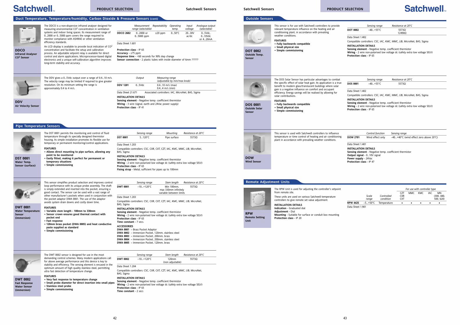
The RPW Unit is used for adjusting the controller’s setpointfrom remote site.
These units are used on various Satchwell temperaturecontrollers to give remote set value adjustment.
INSTALLATION DETAILSIndication - Graduated dialAdjustment - DialMounting - Suitable for surface or conduit box mountingProtection class - IP 20
RPWRemote SettingUnit
For use with controller type
CZT MMC KMC IAC MNScale Controlled CXR (300, 440, range condition CXT 500, 620)
RPW 4425 –5...+50°C Temperature • • • • •Data Sheet 1.901
Remote Adjustment Units
PRODUCT SELECTIONSatchwell Sensors
This sensor is used with Satchwell controllers to influencetemperature or time control of heating and air conditioningplant in accordance with prevailing weather conditions.
DOWWind Sensor
Control function Sensing range
DOW 2701 Wind effect only –40...+40°C (wind effect zero above 20°C)
Data Sheet 1.401
INSTALLATION DETAILSSensing element - Negative temp. coefficient thermistorOutput signal - 0...10V signalPower supply - 24VacProtection class - IP 47
Sensing range Resistance at 20°C
DOS 0001 –40...+55°C 5573Ω
Data Sheet 1.402
Compatible controllers: CSC, IAC, KMC, MMC, LIB, MicroNet, BAS, Sigma
INSTALLATION DETAILSSensing element - Negative temp. coefficient thermistorWiring - 2 wire non-polarised low voltage dc (safety extra low voltage SELV)Protection class - IP 65
The DOS Solar Sensor has particular advantages to combatthe specific effect of solar heat gain. Its application is a truebenefit to modern glass/translucent buildings where solargain is a negative influence on comfort and occupantefficiency. Energy savings will be realised by allowing forsolar contributions.
FEATURES• Fully backwards compatible• Small physical size• Simple commissioning
DOS 0001Outside SolarSensor
Sensing range Resistance at 20°C
DOT 0002 –40...+55°C 5573Ω12490Ω
Data Sheet 1.402
Compatible controllers: CSC, IAC, KMC, MMC, LIB, MicroNet, BAS, Sigma
INSTALLATION DETAILSSensing element - Negative temp. coefficient thermistorWiring - 2 wire non-polarised low voltage dc (safety extra low voltage SELV)Protection class - IP 65
This sensor is for use with Satchwell controllers to providerelevant temperature influence on the heating and airconditioning plant, in accordance with prevailingweather conditions.
FEATURES• Fully backwards compatible• Small physical size• Simple commissioningDOT 0002
Outside Temp.Sensor
Outside Sensors
43
This sensor simplifies product selection and improves controlloop performance with its unique probe assembly. The shaftis simply extended and inserted into the pocket, ensuring agood contact. The sensor can be used with a vast range ofother manufacturer’s pockets when used in conjunction withthe pocket adaptor DWA 0001. The use of the adaptoravoids system drain downs and costly down time.
FEATURES• Variable stem length - 100mm to 330mm• Sensor crown ensures good thermal contact with
pocket end• Fast response• 120mm brass pocket (DWA 0005) and heat conductive
paste supplied as standard• Simple commissioning
Sensing range Stem length Resistance at 20°C
DWT 0001 –10...+120°C Min 100mm, 5573Ωmax 330mm infinitely
variable between limits
Data Sheet 1.203
Compatible controllers: CSC, CXR, CXT, CZT, IAC, KMC, MMC, LIB, MicroNet,BAS, Sigma
INSTALLATION DETAILSSensing element - Negative temp. coefficient thermistorWiring - 2 wire non-polarised low voltage dc (safety extra low voltage SELV)Protection class - IP 65Time constant - 7 secs.
ACCESSORIESDWA 0001 – Brass Pocket AdaptorDWA 0002 – Immersion Pocket, 120mm, stainless steelDWA 0003 – Immersion Pocket, 200mm, brassDWA 0004 – Immersion Pocket, 200mm, stainless steelDWA 0005 – Immersion Pocket, 120mm, brass
DWT 0001Water TemperatureSensor(immersion)
Sensing range Mounting Resistance at 20°C
DST 0001 5...120°C Pipe surface 5573Ω
Data Sheet 1.203
Compatible controllers: CSC, CXR, CXT, CZT, IAC, KMC, MMC, LIB, MicroNet,BAS, Sigma
INSTALLATION DETAILSSensing element - Negative temp. coefficient thermistorWiring - 2 wire non-polarised low voltage dc (safety extra low voltage SELV)Protection class - IP 65Fixing strap - Metal, sufficient for pipes up to 100mm
The DST 0001 permits the monitoring and control of fluidtemperature through its specially designed thermistorhousing. Its simple installation promotes its flexible use fortemporary or permanent monitoring/control applications.
FEATURES• Allows direct mounting to pipe surface, allowing any
point to be monitored• Easily fitted, making it perfect for permanent or
temporary situations• Simple commissioning
DST 0001Water Temp.Sensor (surface)
Pipe Temperature Sensors
The DWT 0002 sensor is designed for use in the mostdemanding control schemes. Many modern applications callfor above average performance and this device is key tostability and efficiency. The sensing element is encased in theoptimum amount of high quality stainless steel, permittingultra fast detection of temperature change.
FEATURES• Very fast response to temperature change• Small probe diameter for direct insertion into small pipes• Stainless steel probe• Simple commissioning
DWT 0002Fast ResponseWater Sensor(immersion)
Sensing range Stem length Resistance at 20°C
DWT 0002 –10...+120°C 120mm 5573Ω(non adjustable)
Data Sheet 1.204
Compatible controllers: CSC, CXR, CXT, CZT, IAC, KMC, MMC, LIB, MicroNet,BAS, Sigma
INSTALLATION DETAILSSensing element - Negative temp. coefficient thermistorWiring - 2 wire non-polarised low voltage dc (safety extra low voltage SELV)Protection class - IP 65Time constant - 2 secs
PRODUCT SELECTION Satchwell Sensors
Output Measuring range(adjustable by min/max knob)
DDV 1201 0...5Vdc 0.4...10 m/s (max)0.4...4 m/s (min)
Data Sheet 21.671 Associated controllers: IAC, MicroNet, BAS, Sigma
INSTALLATION DETAILSSensing element - Negative temp. coefficient thermistorWiring - 3 wire (signal, earth and 24Vac power supply) Protection class - IP 41
The DDV gives a 0...5Vdc output over a range of 0.4...10 m/s.The velocity range may be limited if required to give greaterresolution. On its minimum setting the range isapproximately 0.4 to 4 m/s.
DDVAir Velocity Sensor
The DDCO is a non-dispersive infrared analyser designed formeasuring environmental CO2 concentration in ventilationsystems and indoor living spaces. Its measurement range of0...2000 or 0...5000 ppm covers the range required tomonitor compliance with ASHRAE or other ventilationefficiency standards.
An LCD display is available to provide local indication of CO2
concentration and facilitate the setup and calibrationprocess. An adjustable setpoint relay is available for directcontrol and alarm applications. Microprocessor-based digitalelectronics and a unique self-calibration algorithm improveslong-term stability and accuracy.
DDCOInfrared AnalyserCO2 Sensor
Measurement Repeatability Operating Input Analogue outputrange (selectable) temp. voltage (selectable)
DDCO 2602 0...2000 or ±20 ppm 0...50°C 20...30V 0...5Vdc,0...5000 ppm ac/dc 0...10Vdc
or 4...20mA
Data Sheet 1.601
Protection class - IP 65Accuracy - ±75 ppmResponse time - <60 seconds for 90% step changeSensor connection - 2 plastic tubes with inside diameter of 6mm ??????
Duct Temperature, Temperature/humidity, Carbon Dioxide & Pressure Sensors (cont)
42

45
PRODUCT SELECTIONSatchwell Switches & Thermostats
Transducer
EPTElectro PneumaticTransducer
Input signal Output signal Max supply Input powerpressure
EPT 7401 0...10Vdc 0...20 psi 45 psi 24Vac/dc nominal0...5vdc or 3...15 psi
4...20mA
Data Sheet 25.021
INSTALLATION DETAILSIndication - Output air pressure gauge (indication only)Power on LEDPressure increasing LEDPressure decreasing LED
This transducer is used as an interface between an electroniccontroller and a pneumatically operated control valve ordamper. It is set to receive a 0...10Vdc input and converts itto a proportional 0...20 PSI output signal. The input may beconfigured, if required, for 0...5Vdc or 4...20mA by using thejumpers on the PCB.
FEATURES• Smooth stable linear performance• Choice of input signals to meet most control
applications. 0...10Vdc, 0...5Vdc or 4...20mA selectedfrom onboard jumpers
• LED indication of supply status andincreasing/decreasing pressure signal
• Indication gauge for actual air pressure output• Manual override of output pressure signal
Pipe Temperature Thermostat
The TSM Thermostat is typically used in water controlapplications where it is not possible to insert a pocket intothe pipe. The thermostat is attached to the pipe by a springstrap (supplied).
FEATURES• Simple installation and commissioning• Cable gland supplied
TSMStrap-on PipeThermostat
Sensing range Adjustment Contact rating
TSM 2501 0...90°C Exposed 230Vac, 16ASPDT
Data Sheet 21.003
Ambient temperature limits - Maximum sensing plate temperature 100°CMaximum pipe diameter - 150mmProtection class - IP 40
Outside and Pipe Frost Thermostats
The range of TCL Freeze Thermostats covers both outside,heater battery and water pipe freeze protection.
The TCL 1601 wall mounting freeze thermostat is suitable foroutside mounting.
The TCL 1602 and TCL 1603 have a capillary that will sensethe lowest temperature on the face of the battery or thesurface of a pipe.
TCLAir TemperatureThermostats
Sensing range Type Stem type Contact rating
TCL 1601 –15...+10°C Outside – 230Vac SPDT(auto reset) heating 10A, cooling 3A
TCL 1602 –18...+13°C Coil and pipe Capillary stem 230Vac, 6A(manual reset) (6m) SPDT
TCL 1603 –18...+13°C Coil and pipe Capillary stem (auto reset) (6m)
Data Sheet 21.004
INSTALLATION DETAILSProtection class - TCL 1601: IP 65, TCL 1602/3: IP 43
Pipe Temperature Thermostats and Flow Switches
The SFW Flow Switch is designed to control water flow, inpipe diameters from 1” to 6”, using a paddle to switch onand off the power supply. The paddle can be trimmed tosuit the flow required. It is designed to be mounted in ashort necked welded socket or a tee with a short branch.
SFWWater Flow Switch
Max fluid temp. Contact rating
SFW 1251 85°C 24...230Vac, 15Asingle pole, double throw
Data Sheet 21.670
Head protection class - IP 65
The TWK Thermostat is for water applications andincorporate a single pole double throw contact switch.
FEATURES• Simple installation and commissioning• Cable gland supplied
TWKWater ImmersionThermostat
Sensing range Adjustment Pocket Contact rating
TWK 2301 0...90°C Exposed 1/2” NPT 230Vac, 16A(100mm x 8mm Ø) SPDT
Data Sheet 21.001
Protection class - IP 40Max head temperature - 80°C
These thermostats are typically used in water highlimit/control applications such as HWS cylinders or boilers.
The TWL is a manual reset, high limit thermostat with aSingle Pole Double Throw (SPDT) action. The TWM is acombined control thermostat and manual reset, high limitthermostat allowing independent setting of both the controlpoint and high limit temperature.
FEATURES• Simple installation and commissioning• Cable gland supplied• Manual reset• Concealed setting for reset temperature
TWL, TWMWater ImmersionThermostats(manual reset)
Sensing range Adjustment Pocket Contact rating
TWL 2302 65...85°C Exposed 1/2” NPT 230Vac, 16A(100mm x 8mm Ø) SPDT
TWM 2401 0...90°C (control) Exposed 1/2” NPT70...90°C (limit) Concealed (100mm x 16mm Ø)
Data Sheet 21.002
Protection class - IP 40Max head temperature - 80°C
PRODUCT SELECTION Satchwell Switches & Thermostats
Duct Temperature Thermostats, Pressure and Air Flow Switches
These thermostats are for duct applications and incorporatea single pole double throw contact switch.
FEATURES• Simple installation and commissioning• Cable gland supplied
TDR, TDCAir TemperatureThermostats
Sensing range Adjustment Stem type Contact rating
TDR 2201 0...60°C Exposed Rigid stem 230Vac, 16A(190mm x 8mm Ø) SPDT
TDC 2202 0...60°C Exposed Capillary stem (1 metre)
Data Sheet 21.001
Protection class - IP 40Max head temperature - 80°C
The SPA 1501…1504 Differential Pressure Switches can beused to signal when the pressure difference is too high dueto a blocked filter, too low due to flow failure, or for levelcontrol in a pressurised vessel. Suitable for use on a vacuum.
The SPA 1505 &1506 Pressure Switches can be wired intocontrol circuits or contactors to provide a high or lowpressure cut-out. Alternatively, they can be wired directly toa bell or light to provide a high or low pressure alarm. Notsuitable for use on a vacuum.
SPAUniversalDifferential andUniversal PressureSwitches
This switch is designed to control air flow using a paddle toswitch on and off the power supply. The paddle can betrimmed if the air flow is above 5 metres per second.
SFAAir Flow Switch
Flow setting Contact rating
SFA 1451 1 m/s, 2.5 m/s (paddle untrimmed) 24...230Vac, 15Asingle pole, double throw
Data Sheet 21.670
Head protection class - IP 65
The SPA Differential Pressure Switch is used to monitornon-inflammable and non-aggressive gases. Typicalapplications are filter dirty and fan run/stop detection.
ACCESSORY DDP 3601 Fitting Kit (containing 2 metres ofPVC tubing and 2 duct mounting pitot tubes)
SPAAir DifferentialPressure Switch
Adjustable range Max. operating Repeatability Contact for trip pressure pressure rating
SPA 1401 0.2...3.0 mbar 50 mbar 0.025 mbar 230Vac, 1ASPDT
SPA 1402 1.0...10.0 mbar 50 mbar 0.05 mbar
Data Sheet 21.601
Protection class - IP 54Pressure connection - 2 plastic tubes with inside diameter of 6mm
44
Type Spec. no. Sensing range Reset differential* Contact rating
Universal SPA 1501 150 - 1000 mbar 50 - 100 1A @ 250vDifferentialPressure
SPA 1502 6 - 20 mbar 3 - 8 1A @ 250vSPA 1503 15 - 60 mbar 5 - 16 1A @ 250vSPA 1504 40 - 200 mbar 20 - 60 1A @ 250v
Universal SPA 1505 120 - 2200 mbar 110 - 450 6A @ 250vPressure
SPA 1506 1000 - 6000 mbar 200 - 1500 6A @ 250v
Protection class - SPA 1501-1504 IP 65, SPA 1505/1506 IP 54. *Adjustable between (mbar)Max line pressure - SPA 1501 - 20 bar, SPA 1502-1504 - 10 bar, SPA 1505/1506 - 6 bar
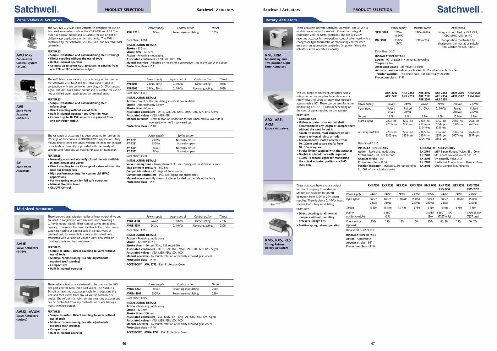
47
PRODUCT SELECTIONSatchwell Actuators
Power supply Transfer switch Application
XRM 3201 24Vac 24Vac/0.02A Integral (controlled by CXT, CXR, (0.5VA) CSC, MMC, URC or IAC
RM 3601 230Vac 230Vac/3A Two-position (controlled by (5VA) changeover thermostat or switch).
Also suitable for CSC, CMC.
Data Sheet 3.201
INSTALLATION DETAILSStroke - 90° angular in 4 minutes. ReversingTorque - 2 NmAssociated valves - MB valves (3-port)Actuator position indicator - Marked 0...10 visible from both sidesTransfer switches - Two single pole. Not electrically separateProtection class - IP 41
These actuators operate Satchwell MB valves. The XRM is amodulating actuator for use with Climatronic integralcontrollers and the MMC controller. The RM is a 230Vreversing actuator for two-position control when used with achangeover type thermostat or modulating control whenused with an appropriate controller. On power failure theactuator can be operated manually.
RM, XRMModulating andTwo-position LightDuty Actuators
Rotary Actuators
ARX 2202 ARX 2252 ARE 2302 ARE 2352 ARM 2606 ARM 2656ARX 2203 ARX 2253 ARE 2303 ARE 2354 ARM 2607 ARM 2657
ARE 2304 ARE 2355
Power supply 24Vac 24Vac 24Vac 24Vac 230Vac 230Vac
Input signal Pulsed Pulsed 0...10Vdc 0...10Vdc Pulsed Pulsed 24Vac 24Vac 230Vac 230Vac
Torque 15 Nm 8 Nm 15 Nm 8 Nm 15 Nm 8 Nm
Start & span 2202-no 2252-no 2302-no 2352-no 2606-no 2656-no2203-no 2253-no 2303-yes 2354 -yes 2607 -no 2657-no
2304-yes 2355 -no
Auxiliary switches 2202-no 2252-no 2302-no 2352-no 2606-no 2656-no2203-yes 2253 -yes 2303 -no 2354-yes 2607 -yes 2657 -yes
2304 -yes 2355 -yes
Data Sheet 3.215
INSTALLATION DETAILSAction - Reversing-modulating Stroke time - 90...220 secondsAngular stroke - 95°Protection class - IP 54Position indicator - Marked 0...10 representing0...100% of the actuator stroke
The ‘AR’ range of Reversing Actuators have arotary output for coupling to air dampers orrotary valves requiring a rotary drive throughapproximately 95°. These can be used for eithermodulating or ON/OFF control depending onthe control signal supplied to the actuator.
FEATURES• Compact size• Hollow actuator drive output shaft
accommodates any length of damper shaftwithout the need to cut it
• Simple to install, most dampers do notrequire universal joints or rods
• Accommodates shaft diameters from10...20mm and square shafts from10...16mm square
• Stroke limiter supplied with the actuator• Double insulated, no earth required• 0...10V Feedback signal for monitoring
the actual actuator position via BMS(ARE only)
ARX, ARE,ARMRotary Actuators
LINKAGE KIT ACCESSORIESLK 2701 MBF 3-port Flanged Valves 65...100mm LK 2702 MB 3-port Screwed Valves 1/2”...2” LK 2703 VV Butterfly Valve 2...4” LK 2407 Traditional Connection to Damper Boxes LK 2408 Direct Damper Mounting Kit
RXS 7254 RXS 7255 RES 7354 RMS 7654 RMS 7655 RXS 7256 RES 7355 RMS 7656RXS 7257 RMS 7657
Power supply 24Vac 24Vac 24Vac 230Vac 230Vac 24Vac 24Vac 230Vac
Input signal Pulsed Pulsed 0...10Vdc Pulsed Pulsed Pulsed 0...10Vdc Pulsed24Vac 24Vac 230Vac 230Vac 24Vac 230Vac
Torque 15 Nm 15 Nm 15 Nm 15 Nm 15 Nm 4 Nm 4 Nm 4 Nm
Built-in - 2 SPDT - - 2 SPDT 1 SPDT (1.5A) - 1 SPDT (1.5A)auxiliary switches (3A) (3A) (7257 only) (7657 only)
Running time 150s 150s 150s 150s 150s 40...70s 150s 40...70s(approx)
Data Sheet 3.305/3.310
INSTALLATION DETAILSAction - Open/closeAngular stroke - 95°Protection class - IP 54
These actuators have a rotary outputfor direct coupling to air dampers.Models are available for on/offoperation from 230V or 24V powersupplies. There is also a 0...10Vdc inputversion that is fully modulating.
FEATURES
• Direct coupling to all normaldampers without mountingbrackets linkage kits
• Positive spring return operation
RMS, RXS, RESSpring ReturnRotary Actuators
Mid-sized Actuators
Power supply Input control Control action Thrust
AVUE 4304 24Vac 0...10Vdc Direct acting 220N
AVUE 4354 24Vac 0...10Vdc Reversing acting 220N
Data Sheet 3.001
INSTALLATION DETAILSAction - Reversing, modulatingStroke - 12.7mm (1/2”)Stroke time - 150 secs/50Hz, 125 secs/60HzAssociated controllers - DRTE, CZT, KMC, MMC, IAC, URC, MN, BAS, SigmaAssociated valves - VEU, MEU, FEU, VZX, MZXManual operator - By thumb rotation of partially exposed gear wheelProtection class - IP 40
ACCESSORY AVA 1752 Rain Protection Cover
These proportional actuators utilise a linear output drive andare used in conjunction with any controller providing a0...10Vdc output signal. These control valves are applied,typically, to regulate the flow of either hot or chilled watersupplying heating or cooling coils in various types ofterminal unit, for example fan coils units, reheat coilsassociated with variable air volume units, also small airhandling plants and heat exchangers.
FEATURES• Simple to install. Direct coupling to valve without
use of tools• Minimal commissioning. No site adjustments
required (self stroking)• Compact size• Built in manual operator
AVUEValve Actuators(0-10V)
Power supply Control action Thrust
AVUX 4202 24Vac Reversing-modulating 220N
AVUM 4601 230Vac Reversing-modulating 220N
Data Sheet 3.005
INSTALLATION DETAILSAction - Reversing, modulatingStroke - 12.7mmStroke time - 100 secsAssociated controllers - CSC, MMC, CXT, CXR, IAC, URC, MN, BAS, SigmaAssociated valves - VEU, MEU, FEU, VZX, MZXManual operator - By thumb rotation of partially exposed gear wheelProtection class - IP 40
ACCESSORY AVUA 1752 Rain Protection Cover
These valve actuators are designed to be used on the VZXtwo port and the MZX three port valves. The AVUX is a24 volt ac reversing actuator suitable for modulating theVZX and MZX valves from any 24 Volt ac controller ordevice. The AVUM is a mains Voltage reversing actuator andcan be controlled from any controller or device having amains switched output.
FEATURES• Simple to install. Direct coupling to valve without
use of tools• Minimal commissioning. No site adjustments
required (self stroking)• Compact size• Built in manual operator
AVUX, AVUMValve Actuators(pulsed)
PRODUCT SELECTION Satchwell Actuators
Zone Valves & Actuators
Power supply Control action Thrust
AVU 2201 24Vac Reversing-modulating 105N
Data Sheet 3.010
INSTALLATION DETAILSStroke - 11.5mmStroke time - 60 secsAction - Reversing-modulatingAssociated controllers - CZU, IAC, URC, MNManual override - Adjusted by means of a screwdriver slot in the top of the coverProtection class - IP 41
The AVU Mk 2, 24Vac Valve Actuator is designed for use onSatchwell zone valves such as the VEU, MEU and FEU. TheAVU has a linear output and is suitable for use on hot orchilled water applications on terminal units. The AVU iscontrolled by the Satchwell CZU, IAC, URC and MicroNet MNcontrollers.
FEATURES• Simple installation and commissioning (self stroking)• Direct coupling without the use of tools• Built-in manual operator• Connect up to seven AVU actuators in parallel from
one CZU or IAC controller output
AVU Mk2ZonemasterControl System(24Vac)
Power supply Spring return
AY 1201 230Vac Normally closedAY 1251 230Vac Normally open
AY 1301 24Vac Normally closedAY 1351 24Vac Normally open
Data Sheet 3.030
INSTALLATION DETAILSValve running time - Power stroke 9...11 secs, Spring return stroke 4...5 secsMax different pressure - 350 kPaCompatible valves - ZY range of Zone ValvesCompatible controllers - IAC, BAS, Sigma and thermostatsManual operation - By means of a lever located on the side of the bodyProtection class - IP 41
The AY range of actuators has been designed for use on theZY range of Zone Valves in ON/OFF HVAC applications. Theymount directly onto the valves without the need for linkagesor calibration. Flexibility is provided with the variety ofvoltages and functions, all making for ease of installation.
FEATURES• Normally open and normally closed models available
in both 230Vac and 24Vac• Direct coupling to the ZY range of valves without the
need for linkage kits• High performance duty for commercial HVAC
applications• Positive spring return for fail safe operation• Manual Override Lever• ON/OFF Control
AYZone ValveActuators
Power supply Input control Control action Thrust
AVE0001 24Vac, 50Hz 0...10Vdc Direct acting 105N
AVE0002 24Vac, 50Hz 0...10Vdc Reversing acting 105N
Data Sheet 3.011
INSTALLATION DETAILSAction - Direct or Reverse Acting specifications availableStroke - Approximately 9.5mmStroke time - 60 secsAssociated controllers - DRTE, CZT, IAC, KMC, MMC, URC, MN, BAS, SigmaAssociated valves - VEU, MEU, FEUManual Override - Reset button on underside for use when manual override is
operated when AVE is powered up.Protection class - IP 40
The AVE 24Vac zone valve actuator is designed for use onthe Satchwell VEU, MEU and FEU valves and is used inconjunction with any controller providing a 0-10Vdc outputsignal. The AVE has a linear output and is suitable for use onhot or chilled water applications on terminal units.
FEATURES• Simple installation and commissioning (self
referencing)• Direct coupling without use of tools• Built-in Manual Operator and Override Reset• Connect up to 10 AVE actuators in parallel from
one controller output
AVEZone ValveActuator(0-10vdz)
46
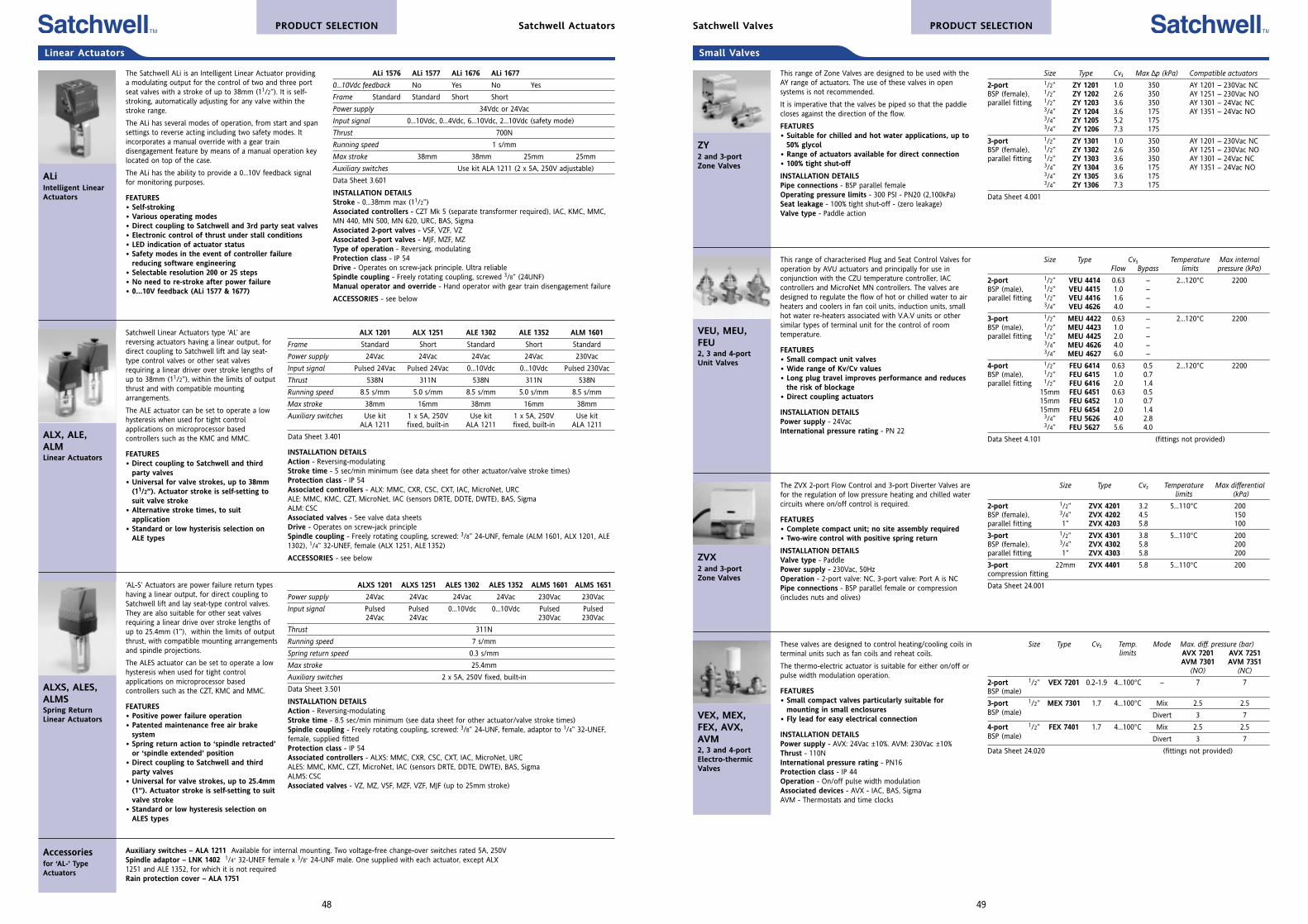
Small Valves
This range of Zone Valves are designed to be used with theAY range of actuators. The use of these valves in opensystems is not recommended.
It is imperative that the valves be piped so that the paddlecloses against the direction of the flow.
FEATURES• Suitable for chilled and hot water applications, up to
50% glycol• Range of actuators available for direct connection• 100% tight shut-off
INSTALLATION DETAILSPipe connections - BSP parallel femaleOperating pressure limits - 300 PSI - PN20 (2,100kPa)Seat leakage - 100% tight shut-off - (zero leakage)Valve type - Paddle action
ZY2 and 3-portZone Valves
Size Type Cvs Temperature Max internalFlow Bypass limits pressure (kPa)
2-port 1/2” VEU 4414 0.63 – 2...120°C 2200BSP (male), 1/2” VEU 4415 1.0 –parallel fitting 1/2” VEU 4416 1.6 –
3/4” VEU 4626 4.0 –
3-port 1/2” MEU 4422 0.63 – 2...120°C 2200BSP (male), 1/2” MEU 4423 1.0 –parallel fitting 1/2” MEU 4425 2.0 –
3/4” MEU 4626 4.0 –3/4” MEU 4627 6.0 –
4-port 1/2” FEU 6414 0.63 0.5 2...120°C 2200BSP (male), 1/2” FEU 6415 1.0 0.7parallel fitting 1/2” FEU 6416 2.0 1.4
15mm FEU 6451 0.63 0.515mm FEU 6452 1.0 0.715mm FEU 6454 2.0 1.4
3/4” FEU 5626 4.0 2.83/4” FEU 5627 5.6 4.0
Data Sheet 4.101 (fittings not provided)
This range of characterised Plug and Seat Control Valves foroperation by AVU actuators and principally for use inconjunction with the CZU temperature controller, IACcontrollers and MicroNet MN controllers. The valves aredesigned to regulate the flow of hot or chilled water to airheaters and coolers in fan coil units, induction units, smallhot water re-heaters associated with V.A.V units or othersimilar types of terminal unit for the control of roomtemperature.
FEATURES• Small compact unit valves• Wide range of Kv/Cv values• Long plug travel improves performance and reduces
the risk of blockage• Direct coupling actuators
INSTALLATION DETAILSPower supply - 24Vac International pressure rating - PN 22
VEU, MEU,FEU2, 3 and 4-portUnit Valves
Size Type Cvs Temperature Max differentiallimits (kPa)
2-port 1/2” ZVX 4201 3.2 5...110°C 200BSP (female), 3/4” ZVX 4202 4.5 150parallel fitting 1” ZVX 4203 5.8 100
3-port 1/2” ZVX 4301 3.8 5...110°C 200BSP (female), 3/4” ZVX 4302 5.8 200parallel fitting 1” ZVX 4303 5.8 200
3-port 22mm ZVX 4401 5.8 5...110°C 200compression fitting
Data Sheet 24.001
ZVX2 and 3-portZone Valves
Size Type Cvs Temp. Mode Max. diff. pressure (bar)limits AVX 7201 AVX 7251
AVM 7301 AVM 7351(NO) (NC)
2-port 1/2” VEX 7201 0.2-1.9 4...100°C – 7 7BSP (male)
3-port 1/2” MEX 7301 1.7 4...100°C Mix 2.5 2.5BSP (male) Divert 3 7
4-port 1/2” FEX 7401 1.7 4...100°C Mix 2.5 2.5BSP (male) Divert 3 7
Data Sheet 24.020 (fittings not provided)
These valves are designed to control heating/cooling coils interminal units such as fan coils and reheat coils.
The thermo-electric actuator is suitable for either on/off orpulse width modulation operation.
FEATURES• Small compact valves particularly suitable for
mounting in small enclosures• Fly lead for easy electrical connection
INSTALLATION DETAILSPower supply - AVX: 24Vac ±10%. AVM: 230Vac ±10%Thrust - 110NInternational pressure rating - PN16Protection class - IP 44Operation - On/off pulse width modulationAssociated devices - AVX - IAC, BAS, Sigma AVM - Thermostats and time clocks
VEX, MEX,FEX, AVX,AVM2, 3 and 4-portElectro-thermicValves
Size Type Cvs Max ∆p (kPa) Compatible actuators
2-port 1/2” ZY 1201 1.0 350 AY 1201 – 230Vac NCBSP (female), 1/2” ZY 1202 2.6 350 AY 1251 – 230Vac NOparallel fitting 1/2” ZY 1203 3.6 350 AY 1301 – 24Vac NC
3/4” ZY 1204 3.6 175 AY 1351 – 24Vac NO3/4” ZY 1205 5.2 1753/4” ZY 1206 7.3 175
3-port 1/2” ZY 1301 1.0 350 AY 1201 – 230Vac NCBSP (female), 1/2” ZY 1302 2.6 350 AY 1251 – 230Vac NOparallel fitting 1/2” ZY 1303 3.6 350 AY 1301 – 24Vac NC
3/4” ZY 1304 3.6 175 AY 1351 – 24Vac NO3/4” ZY 1305 3.6 1753/4” ZY 1306 7.3 175
Data Sheet 4.001
The ZVX 2-port Flow Control and 3-port Diverter Valves arefor the regulation of low pressure heating and chilled watercircuits where on/off control is required.
FEATURES• Complete compact unit; no site assembly required• Two-wire control with positive spring return
INSTALLATION DETAILSValve type - PaddlePower supply - 230Vac, 50HzOperation - 2-port valve: NC, 3-port valve: Port A is NCPipe connections - BSP parallel female or compression(includes nuts and olives)
49
PRODUCT SELECTIONSatchwell Valves
Satchwell Linear Actuators type ‘AL’ arereversing actuators having a linear output, fordirect coupling to Satchwell lift and lay seat-type control valves or other seat valvesrequiring a linear driver over stroke lengths ofup to 38mm (11/2”), within the limits of outputthrust and with compatible mountingarrangements.
The ALE actuator can be set to operate a lowhysteresis when used for tight controlapplications on microprocessor basedcontrollers such as the KMC and MMC.
FEATURES• Direct coupling to Satchwell and third
party valves• Universal for valve strokes, up to 38mm
(11/2”). Actuator stroke is self-setting tosuit valve stroke
• Alternative stroke times, to suitapplication
• Standard or low hysterisis selection onALE types
ALX, ALE,ALMLinear Actuators
Linear Actuators
ALXS 1201 ALXS 1251 ALES 1302 ALES 1352 ALMS 1601 ALMS 1651
Power supply 24Vac 24Vac 24Vac 24Vac 230Vac 230Vac
Input signal Pulsed Pulsed 0...10Vdc 0...10Vdc Pulsed Pulsed 24Vac 24Vac 230Vac 230Vac
Thrust 311N
Running speed 7 s/mm
Spring return speed 0.3 s/mm
Max stroke 25.4mm
Auxiliary switches 2 x 5A, 250V fixed, built-in
Data Sheet 3.501
INSTALLATION DETAILSAction - Reversing-modulatingStroke time - 8.5 sec/min minimum (see data sheet for other actuator/valve stroke times)Spindle coupling - Freely rotating coupling, screwed: 3/8” 24-UNF, female, adaptor to 1/4” 32-UNEF,female, supplied fittedProtection class - IP 54Associated controllers - ALXS: MMC, CXR, CSC, CXT, IAC, MicroNet, URCALES: MMC, KMC, CZT, MicroNet, IAC (sensors DRTE, DDTE, DWTE), BAS, SigmaALMS: CSCAssociated valves - VZ, MZ, VSF, MZF, VZF, MJF (up to 25mm stroke)
ALXS, ALES,ALMSSpring ReturnLinear Actuators
The Satchwell ALi is an Intelligent Linear Actuator providinga modulating output for the control of two and three portseat valves with a stroke of up to 38mm (11/2”). It is self-stroking, automatically adjusting for any valve within thestroke range.
The ALi has several modes of operation, from start and spansettings to reverse acting including two safety modes. Itincorporates a manual override with a gear traindisengagement feature by means of a manual operation keylocated on top of the case.
The ALi has the ability to provide a 0...10V feedback signalfor monitoring purposes.
FEATURES• Self-stroking• Various operating modes• Direct coupling to Satchwell and 3rd party seat valves• Electronic control of thrust under stall conditions• LED indication of actuator status• Safety modes in the event of controller failure
reducing software engineering• Selectable resolution 200 or 25 steps• No need to re-stroke after power failure• 0...10V feedback (ALi 1577 & 1677)
ALiIntelligent LinearActuators
Auxiliary switches – ALA 1211 Available for internal mounting. Two voltage-free change-over switches rated 5A, 250VSpindle adaptor – LNK 1402 1/4” 32-UNEF female x 3/8” 24-UNF male. One supplied with each actuator, except ALX1251 and ALE 1352, for which it is not requiredRain protection cover – ALA 1751
‘AL-S’ Actuators are power failure return typeshaving a linear output, for direct coupling toSatchwell lift and lay seat-type control valves.They are also suitable for other seat valvesrequiring a linear drive over stroke lengths ofup to 25.4mm (1”), within the limits of outputthrust, with compatible mounting arrangementsand spindle projections.
The ALES actuator can be set to operate a lowhysteresis when used for tight controlapplications on microprocessor basedcontrollers such as the CZT, KMC and MMC.
FEATURES• Positive power failure operation• Patented maintenance free air brake
system• Spring return action to ‘spindle retracted’
or ‘spindle extended’ position• Direct coupling to Satchwell and third
party valves• Universal for valve strokes, up to 25.4mm
(1”). Actuator stroke is self-setting to suitvalve stroke
• Standard or low hysteresis selection onALES types
ALX 1201 ALX 1251 ALE 1302 ALE 1352 ALM 1601
Frame Standard Short Standard Short Standard
Power supply 24Vac 24Vac 24Vac 24Vac 230Vac
Input signal Pulsed 24Vac Pulsed 24Vac 0...10Vdc 0...10Vdc Pulsed 230Vac
Thrust 538N 311N 538N 311N 538N
Running speed 8.5 s/mm 5.0 s/mm 8.5 s/mm 5.0 s/mm 8.5 s/mm
Max stroke 38mm 16mm 38mm 16mm 38mm
Auxiliary switches Use kit 1 x 5A, 250V Use kit 1 x 5A, 250V Use kit ALA 1211 fixed, built-in ALA 1211 fixed, built-in ALA 1211
Data Sheet 3.401
INSTALLATION DETAILSAction - Reversing-modulatingStroke time - 5 sec/min minimum (see data sheet for other actuator/valve stroke times)Protection class - IP 54Associated controllers - ALX: MMC, CXR, CSC, CXT, IAC, MicroNet, URCALE: MMC, KMC, CZT, MicroNet, IAC (sensors DRTE, DDTE, DWTE), BAS, SigmaALM: CSCAssociated valves - See valve data sheetsDrive - Operates on screw-jack principleSpindle coupling - Freely rotating coupling, screwed: 3/8” 24-UNF, female (ALM 1601, ALX 1201, ALE1302), 1/4” 32-UNEF, female (ALX 1251, ALE 1352)
ACCESSORIES - see below
Accessoriesfor ‘AL-’ TypeActuators
48
PRODUCT SELECTION Satchwell Actuators
ALi 1576 ALi 1577 ALi 1676 ALi 1677
0...10Vdc feedback No Yes No Yes
Frame Standard Standard Short Short
Power supply 34Vdc or 24Vac
Input signal 0...10Vdc, 0...4Vdc, 6...10Vdc, 2...10Vdc (safety mode)
Thrust 700N
Running speed 1 s/mm
Max stroke 38mm 38mm 25mm 25mm
Auxiliary switches Use kit ALA 1211 (2 x 5A, 250V adjustable)
Data Sheet 3.601
INSTALLATION DETAILSStroke - 0...38mm max (11/2”)Associated controllers - CZT Mk 5 (separate transformer required), IAC, KMC, MMC,MN 440, MN 500, MN 620, URC, BAS, SigmaAssociated 2-port valves - VSF, VZF, VZAssociated 3-port valves - MJF, MZF, MZType of operation - Reversing, modulatingProtection class - IP 54Drive - Operates on screw-jack principle. Ultra reliableSpindle coupling - Freely rotating coupling, screwed 3/8” (24UNF)Manual operator and override - Hand operator with gear train disengagement failure
ACCESSORIES - see below

Satchwell Actuators to Satchwell Valves and Dampers
LK 2701, 2702,2703, 2408,2407
RM, XRM, ARM, ARX, ARE Actuators to ...Valve type Suitable actuators Linkage kit Comprises
MB Valves RM, XRM None –1/2”...2” require
ARM 2657 LK 2702 BracketARX 2253 (826-2-702) 2 x screwsARE 2354 Output shaft adapter
MBF Valves ARM 2607 LK 2701 Bracket65...100mm ARX 2203 (826-2-701) Actuator crank with pin
ARE 2304 Valve crank with slot andmanual override lever
VV Valves ARM 2607 LK 2703 Bracket, linkage, screws2...4” ARX 2203 (826-2-703) and spring
ARE 2304
Data sheet 5.001
Valve type Suitable actuators Linkage kit Comprises
Dampers ARM 2607 LK 2407 BracketARX 2203 (866-2-407) Output shaftARE 2304 Adjustable crankARM 2657 Universal couplingARX 2253 Universal coupling forARE 2354 damper
ARM 2607 LK 2408 Anti-rotation bracketARX 2203 (866-2-408) Stroke limiterARE 2304ARM 2657ARX 2253ARE 2354
Data sheet 5.001
51
Size Type Cvs Stroke Max ∆p Temperature limitspressure (kPa) (max internal pressure kPa)
MZ 1/2” MZ 3402 2.5 9.5mm 1600 2...200°CScrewed 3/4” MZ 3452 4 1600 at (1300 kPa)bronze 1” MZ 3501 8 15.9mm 970 or 2...120°C
11/4” MZ 3551 12 580 at (1600 kPa)
11/2” MZ 3601 20 4102” MZ 3651 32 240
MJF 15mm MJF 3426 1.0 9.5mm 1600 2...200°CFlanged 15mm MJF 3427 4.0 1600 at (1300 kPa)cast iron 20mm MJF 3476 6.3 15.9mm 1300 or 2...120°C
25mm MJF 3526 10 850 at (1600 kPa)
32mm MJF 3576 16 24.5mm 55040mm MJF 3626 25 35050mm MJF 3676 40 220
MZF 65mm MZF 3729 63 25.4mm 140 2...200°CFlanged 80mm MZF 3779 80 100 at (1300 kPa)cast iron 100mm MZF 3854 125 50 or 2...120°C
125mm MZF 3904 200 38mm 28 at (1600 kPa)
150mm MZF 3958 315 18
Data Sheet 4.610
These ‘Globe’ construction Seat Valves are suitable for thecontrol of hot or chilled water and brine or glycol solutionswithin the limits below.
INSTALLATION DETAILSPipe connections - Screwed BSP to BS 21 female - taperScrewed BSP to BS 21 female - parallelFlanged BS 4504 16/11. = DIN 2533 ND 16Control medium - Brine, 15% max. NaCl or CaCl2 (freezeprotection), Glycol solution, 25% max. (freeze protection)International pressure rating - PN16
ACCESSORIESReplacement Gland Kits 626-9-203 MZ, MJF 626-9-311 MZF
MZ, MZF, MJF3-port Seat Valves
3-port Valves (cont)
PRODUCT SELECTIONSatchwell Valves & Linkage Kits
LNK LS01LNK HW01LNK FS01LNK FS02LNK HY01LNK HY02LNK IN01
ALX, ALE, ALM, ALi Actuators* to ...Valve type Linkage kit Comprises
Landis & Staefa LNK LS01 –VVF and VXF 20mm valve stroke
Honeywell LNK HW01 –V5011A 20mm valve stroke
FisherY body 3/4”...11/2”, A body 11/2” LNK FS01 –Y body 2”...3”, A body 2”...4” LNK FS02 –
Hymatic1700 3/4”...11/2”, 1450 11/4”, 1400R 11/2” LNK HY01 –1400R 2”...3”, 1700 2”...3” LNK HY02 –
SiebeVB valves up to 2” LNK IN01 –
Data sheet 3.601 * Not ALX 1251 and ALE 1352
Satchwell Actuators to Third Party Valves
Transformers
If mains voltage electricity supply is available locally,e.g. at a fan coil unit, it is convenient to use one transformerfor each control system. If mains supply is not availablelocally it may be more convenient to use a larger centraltransformer.
Two fly leads are provided for the primary and secondaryelectrical connections, for ease of installation.
These transformers conform to EN 60742.230Vac/24VacIsolatingTransformers
Code Size
TR1 871-1-201 25VATR2 871-1-202 50VATR3 871-1-203 80VATR4 871-1-204 200VATR5 871-1-205 300VA
Data Sheet 25.001
INSTALLATION DETAILS
Primary - 230V, 50/60 HzSecondary - 24V r.m.s.Electrical connections - 3-core input (fly lead) cable, 0.5m long2-core output (fly lead) cable, 0.5m long
These 3-port Rotary-shoe Type Valves are characterised foruse as mixing or diverting, with hot or chilled water, inheating, ventilating and air conditioning applications.
INSTALLATION DETAILSPipe connections - Screwed parallel (female) BSP to BS 21Flanged BS 4504, Table 6/11International pressure rating - MB: PN10,MBF: PN6
ACCESSORIESReconditioning Kits617-9-410 MB 1/2...1” 618-9-510 MBF 65mm617-9-411 MB 11/4” 618-9-511 MBF 80mm617-9-412 MB 11/2” 618-9-512 MBF 100mm 617-9-413 MB 2”MB, MBF, MBX
3-port RotaryValves
Size Type Cvs Max internal Temperaturepressure (kPa) limits (kPa)
MB 1/2” MB 1402 1.8 1000 2...120°CScrewed 3/4” MB 1452 4.0BSP parallel 1” MB 1502 8.0female 11/4” MB 1552 12.0
11/2” MB 1602 20.02” MB 1652 32.0
MBF 65mm MBF 4732 63 600 2...120°CFlanged 80mm MBF 4782 80
100mm MBF 4857 120
MBX 1/2” MBX 4401 1.8 1000 2...110°CScrewed 3/4” MBX 4451 4.0BSP parallel 1” MBX 4501 8.0female 11/4” MBX 4551 12.0
11/2” MBX 4601 20.02” MBX 4651 32.0
Data Sheet 4.501 & 4.502
Size Type Cvs Stroke Max ∆p Max internal Temp.pressure pressure limits
(kPa) (kPa)
MZX 1/2” MZX 4402 2.5 12.7mm 1180 1600 2...120°CScrewed 3/4” MZX 4452 4 720BSP bronze 1” MZX 4501 8 340
11/4” MZX 4551 12 20011/2” MZX 4601 20 120
2” MZX 4651 32 60
Data Sheet 4.601
These ‘Globe’ construction valves are suitable for the controlof hot or chilled water and brine or glycol solutions withintheir limits - see DS 4.601. They are suitable for operation bythe AVUM, AVUX and AVUE actuators only.
INSTALLATION DETAILSPipe connections - Screwed BSP to BS 21 female - taperScrewed BSP to BS 21 female - parallelControl medium - Brine, 15% max. NaCl or CaCl2 (freezeprotection), Glycol solution, 25% max. (freeze protection)International pressure rating - PN16
ACCESSORY626-9-204 Replacement Gland Kit
MZX3-port Seat Valves
Size Type Cvs Stroke Max ∆p Temperature limits Springpressure (max internal access.
(kPa) pressure kPa) kit
VZ 1/2” VZ 1401 0.2 9.5mm 1600 2...130°C –Screwed 1/2” VZ 1402 0.5 1600 at (1500 kPa) –bronze 1/2” VZ 1403 1.0 1600 or 2...120°C –
1/2” VZ 1404 2.0 1600 at (1600 kPa) –3/4” VZ 1451 4.0 1600 –
1” VZ 2501 8 15.9mm 970 2...200°C 823-2-80111/4” VZ 2551 12 580 at (1300 kPa) ”11/2” VZ 2601 20 410 or 2...120°C ”2” VZ 2651 32 240 at (1600 kPa) ”
VSF 15mm VSF 2426 0.63 9.5mm 1600 “ –Flanged 15mm VSF 2427 1.0 1600 –SG iron 15mm VSF 2428 1.6 1600 –
15mm VSF 2429 2.5 1600 –15mm VSF 2430 4.0 1600 –
VSF 20mm VSF 1476 6.3 15.9mm 1600 “ –Flanged 25mm VSF 1526 10 1170 823-2-801cast iron 32mm VSF 1576 16 24.5mm 640 “ 823-2-801
40mm VSF 1626 25 400 ”50mm VSF 1676 40 240 ”
VZF 65mm VZF 1727 63 25.4mm 140 “ –Flanged 80mm VZF 1777 80 100 –cast iron 100mm VZF 1852 125 50 –
125mm VZF 1902 200 38mm 28 “ –150mm VZF 1954 315 18 –
Data Sheet 4.410
VZ, VZF, VSF2-port Seat Valves
3-port Valves
These seat valves are of ‘Globe’ construction with a linearmoving spindle and equal percentage characterised plugwhich closes against the seat when the spindle is lifted.They are suitable for the control of hot or chilled water,steam, brine or glycol solutions within their limitations– see data sheet.
INSTALLATION DETAILSPipe connections - Screwed BSP to BS 21 female - taperScrewed BSP to BS 21 female - parallelFlanged BS 4504 16/11 = DIN 2533 ND 16Face to Face dimension to DIN 3300International pressure rating - PN16
ACCESSORIESReplacement Gland Kits626-9-203 VZ, VSF 15, 20 & 25mm 667-9-201 VSF 32...50mm626-9-311 VZF Spring Accessory Kit 823-2-801- Available for use inconjunction with ALM 1601, ALX 1201, ALE 1302, to increasemaximum differential pressure.
50
Size Type Cvs Stroke Max ∆p Temperaturepressure (kPa) limits
VZX 1/2” VZX 4404 2 12.7mm 1180 2...120°CScrewed, 3/4” VZX 4451 4 720bronze 1” VZX 4501 8 340
11/4” VZX 4551 12 20011/2” VZX 4601 20 1202” VZX 4651 32 60
Data Sheet 4.401
ACCESSORY626-9-204 Replacement Gland Kit
These seat valves are of ‘Globe’ construction with a linearmoving spindle and equal percentage characterised plugwhich closes against the seat when the spindle is lifted.
The valves are suitable for the control of hot or chilledwater and brine or glycol solutions within their limits – seedata sheet. They are suitable for operation by the AVUX,AVUM and AVUE actuators only.
INSTALLATION DETAILSPipe connections - Screwed BSP to BS 21 female – taperScrewed BSP to BS21 female - parallelCharacteristic - Equal percentageRangeability - 50:1International pressure rating - PN16
VZX2-port Seat Valves
2-port Valves
PRODUCT SELECTION Satchwell Valves
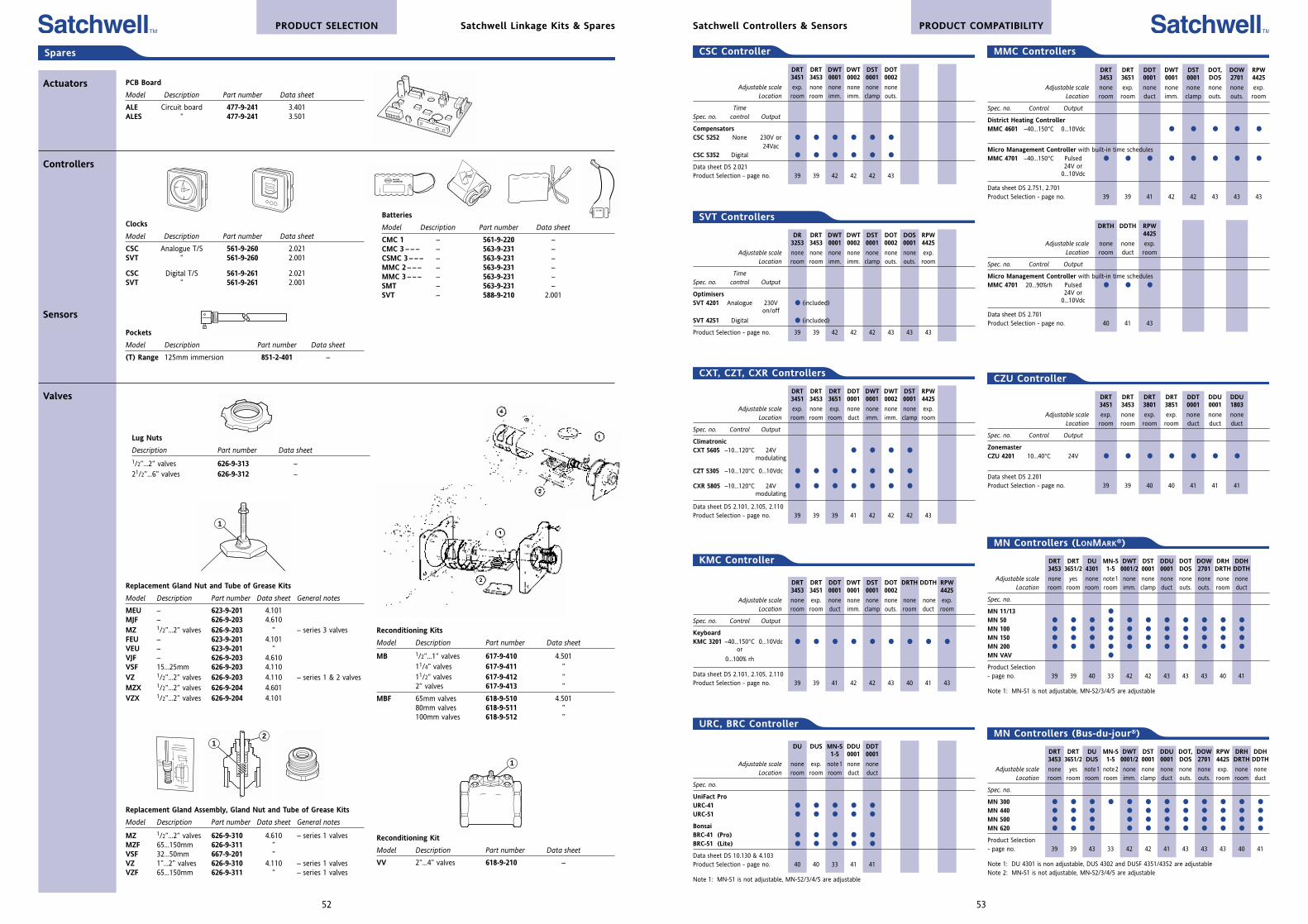
DRT DRT DU MN-S DWT DST DDU DOT, DOW RPW DRH DDH3453 3651/2 DUS 1-5 0001/2 0001 0001 DOS 2701 4425 DRTH DDTH
Adjustable scale none yes note1 note2 none none none none none exp. none noneLocation room room room room imm. clamp duct outs. outs. room room duct
Spec. no.
MN 300
MN 440
MN 500
MN 620
Product Selection - page no. 39 39 43 33 42 42 41 43 43 43 40 41
Note 1: DU 4301 is non adjustable, DUS 4302 and DUSF 4351/4352 are adjustableNote 2: MN-S1 is not adjustable, MN-S2/3/4/5 are adjustable
DR DRT DWT DWT DST DOT DOS RPW3253 3453 0001 0002 0001 0002 0001 4425
Adjustable scale none none none none none none none exp.Location room room imm. imm. clamp outs. outs. room
Time Spec. no. control Output
OptimisersSVT 4201 Analogue 230V (included)
on/off
SVT 4251 Digital (included)
Product Selection - page no. 39 39 42 42 42 43 43 43
DRT DRT DWT DWT DST DOT3451 3453 0001 0002 0001 0002
Adjustable scale exp. none none none none noneLocation room room imm. imm. clamp outs.
Time Spec. no. control Output
CompensatorsCSC 5252 None 230V or
24VacCSC 5352 Digital
Data sheet DS 2.021Product Selection - page no. 39 39 42 42 42 43
CSC Controller
SVT Controllers
DRT DRT DRT DDT DWT DWT DST RPW3451 3453 3651 0001 0001 0002 0001 4425
Adjustable scale exp. none exp. none none none none exp.Location room room room duct imm. imm. clamp room
Spec. no. Control Output
ClimatronicCXT 5605 –10...120°C 24V
modulating
CZT 5305 –10...120°C 0...10Vdc
CXR 5805 –10...120°C 24V modulating
Data sheet DS 2.101, 2.105, 2.110Product Selection - page no. 39 39 39 41 42 42 42 43
CXT, CZT, CXR Controllers
DRT DRT DDT DWT DST DOT, DOW RPW3453 3651 0001 0001 0001 DOS 2701 4425
Adjustable scale none exp. none none none none none exp.Location room room duct imm. clamp outs. outs. room
Spec. no. Control Output
District Heating ControllerMMC 4601 –40...150°C 0...10Vdc
Micro Management Controller with built-in time schedulesMMC 4701 –40...150°C Pulsed
24V or0...10Vdc
Data sheet DS 2.751, 2.701Product Selection - page no. 39 39 41 42 42 43 43 43
MMC Controllers
DRTH DDTH RPW4425
Adjustable scale none none exp.Location room duct room
Spec. no. Control Output
Micro Management Controller with built-in time schedulesMMC 4701 20...90%rh Pulsed
24V or0...10Vdc
Data sheet DS 2.701Product Selection - page no. 40 41 43
DRT DRT DRT DRT DDT DDU DDU3451 3453 3801 3851 0001 0001 1803
Adjustable scale exp. none exp. exp. none none noneLocation room room room room duct duct duct
Spec. no. Control Output
ZonemasterCZU 4201 10...40°C 24V
Data sheet DS 2.201Product Selection - page no. 39 39 40 40 41 41 41
CZU Controller
53
MN Controllers (Bus-du-jour®)
MN Controllers (LONMARK®)
DRT DRT DU MN-S DWT DST DDU DOT DOW DRH DDH3453 3651/2 4301 1-5 0001/2 0001 0001 DOS 2701 DRTH DDTH
Adjustable scale none yes none note1 none none none none none none noneLocation room room room room imm. clamp duct outs. outs. room duct
Spec. no.
MN 11/13
MN 50
MN 100
MN 150
MN 200
MN VAV
Product Selection - page no. 39 39 40 33 42 42 43 43 43 40 41
Note 1: MN-S1 is not adjustable, MN-S2/3/4/5 are adjustable
DRT DRT DDT DWT DST DOT DRTH DDTH RPW3453 3451 0001 0001 0001 0002 4425
Adjustable scale none exp. none none none none none none exp.Location room room duct imm. clamp outs. room duct room
Spec. no. Control Output
KeyboardKMC 3201 –40...150°C 0...10Vdc
or
0...100% rh
Data sheet DS 2.101, 2.105, 2.110Product Selection - page no. 39 39 41 42 42 43 40 41 43
KMC Controller
PRODUCT COMPATIBILITYSatchwell Controllers & Sensors
DU DUS MN-S DDU DDT1-5 0001 0001
Adjustable scale none exp. note1 none noneLocation room room room duct duct
Spec. no.
UniFact ProURC-41
URC-51
BonsaiBRC-41 (Pro)
BRC-51 (Lite)
Data sheet DS 10.130 & 4.103Product Selection - page no. 40 40 33 41 41
Note 1: MN-S1 is not adjustable, MN-S2/3/4/5 are adjustable
URC, BRC Controller
Spares
Actuators PCB Board
Model Description Part number Data sheet
ALE Circuit board 477-9-241 3.401ALES ” 477-9-241 3.501
Controllers
Sensors
Valves
Clocks
Model Description Part number Data sheet
CSC Analogue T/S 561-9-260 2.021SVT ” 561-9-260 2.001
CSC Digital T/S 561-9-261 2.021SVT ” 561-9-261 2.001
Batteries
Model Description Part number Data sheet
CMC 1 – 561-9-220 –CMC 3 – – – – 563-9-231 –CSMC 3 – – – – 563-9-231 –MMC 2 – – – – 563-9-231 –MMC 3 – – – – 563-9-231 –SMT – 563-9-231 –SVT – 588-9-210 2.001
Pockets
Model Description Part number Data sheet
(T) Range 125mm immersion 851-2-401 –
Lug Nuts
Description Part number Data sheet
1/2”...2” valves 626-9-313 –21/2”...6” valves 626-9-312 –
Replacement Gland Nut and Tube of Grease Kits
Model Description Part number Data sheet General notes
MEU – 623-9-201 4.101MJF – 626-9-203 4.610MZ 1/2”...2” valves 626-9-203 ” – series 3 valvesFEU – 623-9-201 4.101VEU – 623-9-201 ”VJF – 626-9-203 4.610VSF 15...25mm 626-9-203 4.110VZ 1/2”...2” valves 626-9-203 4.110 – series 1 & 2 valvesMZX 1/2”...2” valves 626-9-204 4.601VZX 1/2”...2” valves 626-9-204 4.101
Reconditioning Kit
Model Description Part number Data sheet
VV 2”...4” valves 618-9-210 –
1
12
1
Reconditioning Kits
Model Description Part number Data sheet
MB 1/2”...1” valves 617-9-410 4.50111/4” valves 617-9-411 ”11/2” valves 617-9-412 ”2” valves 617-9-413 ”
MBF 65mm valves 618-9-510 4.50180mm valves 618-9-511 ”100mm valves 618-9-512 ”
Replacement Gland Assembly, Gland Nut and Tube of Grease Kits
Model Description Part number Data sheet General notes
MZ 1/2”...2” valves 626-9-310 4.610 – series 1 valvesMZF 65...150mm 626-9-311 ”VSF 32...50mm 667-9-201 ”VZ 1”...2” valves 626-9-310 4.110 – series 1 valvesVZF 65...150mm 626-9-311 ” – series 1 valves
52
PRODUCT SELECTION Satchwell Linkage Kits & Spares
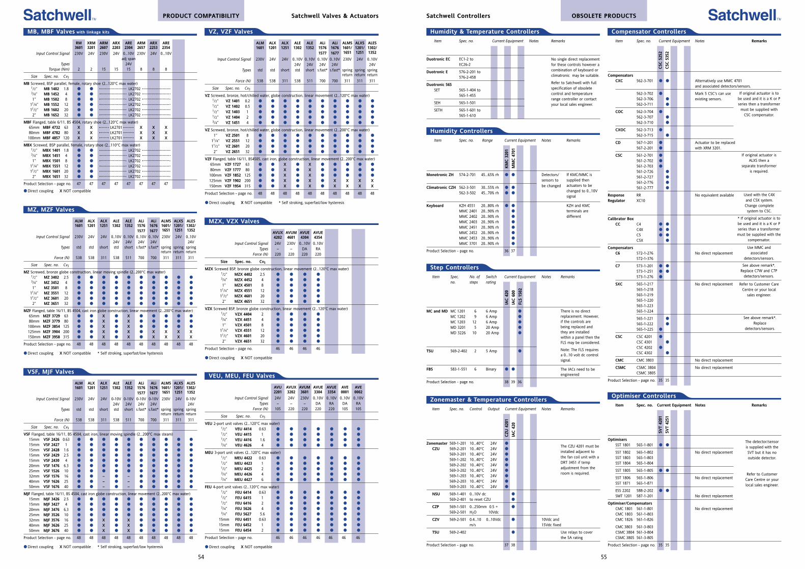
Item Spec. no. Current Equipment Notes Remarks
CompensatorsCXC 562-3-701 Alternatively use MMC 4701
and associated detectors/sensors.
562-3-702 Mark 5 CSC's can use562-3-706 existing sensors.562-3-711
COC 562-3-704
562-3-707
562-3-710
CXOC 562-3-713
562-3-715
CD 567-1-201 Actuator to be replaced 567-2-201 with XRM 3201.
CSC 561-2-701
561-2-702
561-2-703
561-2-726
561-2-727
561-2-776
561-2-777
Response RR No equivalent availableRegulator XC10
Calibrator Box CC C4
C4X
C5
C5X
CompensatorsC6 572-1-276 No direct replacement
572-1-376
C7 573-1-201
573-1-251
573-1-276
SXC 565-1-217 No direct replacement565-1-218565-1-219565-1-220565-1-223565-1-224
565-1-221
565-1-222
565-1-225
CSC CSC 4201
CSC 4301
CSC 4202
CSC 4302
CMC CMC 3803 No direct replacement
CSMC CSMC 3804 No direct replacementCSMC 3805
Product Selection - page no. 35 35
Item Spec. no. Range Current Equipment Notes Remarks
Monotronic ZH 574-2-701 45...65% rh Detectors/sensors to
Climatronic CZH 562-3-501 30...55% rh be changed
562-3-502 45...70% rh
Keyboard KZH 4551 20...80% rh
MMC 2401 20...90% rh
MMC 2402 20...90% rh
MMC 2403 20...90% rh
MMC 2451 20...90% rh
MMC 2452 20...90% rh
MMC 2453 20...90% rh
MMC 3701 20...90% rh
Product Selection - page no. 36 37
If original actuator is tobe used and it is a K or Pseries then a transformer
must be supplied withCSC compensator.
If original actuator isALXS then a
separate transformeris required.
Used with the C4Xand C5X system.Change complete
system to CSC.
* If original actuator is tobe used and it is a K or Pseries than a transformermust be supplied with the
compensator.
Use MMC andassociated
detectors/sensors.
See above remark*.Replace C7W and C7P
detectors/sensors.
Refer to Customer CareCentre or your local
sales engineer.
See above remark*.Replace
detectors/sensors.
CSC
525
2
CSC
535
2
Compensator Controllers
Item Spec. no. Current Equipment Notes Remarks
Duotronic EC EC1-2 to EC26-2
Duotronic E 576-2-201 to 576-2-458
Duotronic 565SET 565-1-404 to
565-1-455
SEH 565-1-501
SETH 565-1-601 to565-1-610
Humidity & Temperature Controllers
No single direct replacementfor these controls however acombination of keyboard orclimatronic may be suitable.
Refer to Satchwell with fullspecification of obsoletecontrol and temperaturerange controller or contactyour local sales engineer.
Humidity Controllers
If KMC/MMC issupplied thenactuators to bechanged to 0...10Vsignal
KZH and KMCterminals aredifferent
KM
C 3
201
MM
C 4
701
Item Spec. No. of Switch Current Equipment Notes Remarksno. steps rating
MC and MD MC 1201 6 6 Amp
MC 1202 9 6 Amp
MC 1203 12 6 Amp
MD 3201 5 20 Amp
MD 3226 10 20 Amp
TSU 569-2-402 2 5 Amp
FBS 583-1-551 6 Binary
Product Selection - page no. 38 39 36
Step Controllers
There is no directreplacement. However,if the controls arebeing replaced andthey are installedwithin a panel then theFLS may be considered.
Note: The FLS requiresa 0...10 volt dc controlsignal.
The IACs need to beengineered
IAC
420
IAC
600
FLS
1502
Item Spec. no. Control Output Current Equipment Notes Remarks
Zonemaster 569-1-201 10...40°C 24V
CZU 569-2-201 10...40°C 24V
569-3-201 10...40°C 24V
569-1-202 10...40°C 24V
569-2-202 10...40°C 24V
569-3-202 10...40°C 24V
569-1-203 10...40°C 24V
569-2-203 10...40°C 24V
569-3-203 10...40°C 24V
NSU 569-1-401 0...10V dc
569-2-401 to reset CZU
CZP 569-1-501 0...250mm 0.5 +
569-2-501 H2O 10Vdc
CZV 569-2-501 0.4...10 0...10Vdc 10Vdc andm/s 15Vdc fixed
TSU 569-2-402 Use relays to coverthe 5A rating
Product Selection - page no. 37 38
Zonemaster & Temperature Controllers
The CZU 4201 must beinstalled adjacent tothe fan coil unit with aDRT 3451 if tempadjustment from theroom is required.
CZU
420
1
IAC
420
Item Spec. no. Current Equipment Notes Remarks
OptimisersSST 1801 565-1-801
SST 1802 565-1-802 No direct replacementSST 1803 565-1-803SST 1804 565-1-804
SST 1805 565-1-805
SST 1806 565-1-806 No direct replacementSST 1871 565-1-871
ESS 2202 588-2-202
SMT 1201 587-1-201 No direct replacement
Optimiser/CompensatorsCMC 1801 561-1-801 No direct replacementCMC 1803 561-1-803CMC 1826 561-1-826
CMC 3803 561-3-803CSMC 3804 561-3-804CSMC 3805 561-3-805
Product Selection - page no. 35 35
SVT
4201
SVT
4251
Optimiser Controllers
The detector/sensoris supplied with theSVT but it has nooutside detector.
Refer to CustomerCare Centre or yourlocal sales engineer.
55
OBSOLETE PRODUCTSSatchwell Controllers
ALM ALX ALX ALE ALE ALi ALi ALMS ALXS ALES1601 1201 1251 1302 1352 1576 1676 1601/ 1201/ 1302/
1577 1677 1651 1251 1352
Input Control Signal 230V 24V 24V 0-10V 0-10V 0-10V 0-10V 230V 24V 0-10V24V 24V 24V 24V 24V
Types std std short std short s.fast* s.fast* spring spring springreturn return return
Force (N) 538 538 311 538 511 700 700 311 311 311
Size Spec. no. CvS
VSF Flanged, table 16/11, BS 4504, cast iron, linear moving spindle (2...200°C max steam)15mm VSF 2426 0.63
15mm VSF 2427 1
15mm VSF 2428 1.6
15mm VSF 2429 2.5
15mm VSF 2430 4
20mm VSF 1476 6.3
25mm VSF 1526 10
32mm VSF 1576 16 – –
40mm VSF 1626 25 – –
50mm VSF 1676 40 – –
MJF Flanged, table 16/11, BS 4504, cast iron globe construction, linear movement (2...200°C max water)15mm MJF 3426 2.5
15mm MJF 3427 4
20mm MJF 3476 6.3
25mm MJF 3526 10
32mm MJF 3576 16 X X
40mm MJF 3626 25 X X
50mm MJF 3676 40 X X
Product Selection - page no. 48 48 48 48 48 48 48 48 48 48
Direct coupling X NOT compatible * Self stroking, superfast/low hysteresis
AVU AVUX AVUM AVUE AVUE AVE AVE2201 3202 3601 3304 3354 0001 0002
Input Control Signal 24V 24V 230V 0..10V 0..10V 0..10V 0..10VTypes – – – DA RA DA RA
Force (N) 105 220 220 220 220 105 105
Size Spec. no. CvS
VEU 2-port unit valves (2...120°C max water)1/2” VEU 4414 0.63 1/2” VEU 4415 1 1/2” VEU 4416 1.6 3/4” VEU 4626 4
MEU 3-port unit valves (2...120°C max water)1/2” MEU 4422 0.63 1/2” MEU 4423 1 1/2” MEU 4425 2 3/4” MEU 4426 4 3/4” MEU 4427 6
FEU 4-port unit valves (2...120°C max water)1/2” FEU 6414 0.63 1/2” FEU 6415 1 1/2” FEU 6416 2 3/4” FEU 5626 4 3/4” FEU 5627 5.6
15mm FEU 6451 0.63
15mm FEU 6452 1
15mm FEU 6454 2
Product Selection - page no. 46 46 46 46 46 46 46
Direct coupling X NOT compatible
AVUX AVUM AVUE AVUE4202 4601 4304 4354
Input Control Signal 24V 230V 0...10V 0..10VTypes – – DA RA
Force (N) 220 220 220 220
Size Spec. no. CvS
MZX Screwed BSP, bronze globe construction, linear movement (2...120°C max water)1/2” MZX 4402 2.5 3/4” MZX 4452 4
1” MZX 4501 8
11/4” MZX 4551 12
11/2” MZX 4601 20
2” MZX 4651 32
VZX Screwed BSP, bronze globe construction, linear movement (2...120°C max water)1/2” VZX 4404 2 3/4” VZX 4451 4
1” VZX 4501 8
11/4” VZX 4551 12
11/2” VZX 4601 20
2” VZX 4651 32
Product Selection - page no. 46 46 46 46
Direct coupling X NOT compatible
RM XRM ARM ARX ARE ARM ARX ARE3601 3201 2607 2203 2304 2657 2253 2354
Input Control Signal 230V 24V 230V 24V 0...10V 230V 24V 0...10Vadj span
Types 24VTorque (Nm) 2 2 15 15 15 8 8 8
Size Spec. no. CvS
MB Screwed, BSP parallel, female, rotary shoe (2...120°C max water)1/2” MB 1402 1.8 LK27023/4” MB 1452 4 LK27021” MB 1502 8 LK2702
11/4” MB 1552 12 LK270211/2” MB 1602 20 LK27022” MB 1652 32 LK2702
MBF Flanged, table 6/11, BS 4504, rotary shoe (2...120°C max water)65mm MBF 4732 63 X X LK2701 X X X80mm MBF 4782 80 X X LK2701 X X X100mm MBF 4857 120 X X LK2701 X X X
MBX Screwed, BSP parallel, female, rotary shoe (2...110°C max water)1/2” MBX 1401 1.8 LK27023/4” MBX 1451 4 LK27021” MBX 1501 8 LK2702
11/4” MBX 1551 12 LK270211/2” MBX 1601 20 LK27022” MBX 1651 32 LK2702
Product Selection - page no. 47 47 47 47 47 47 47 47
Direct coupling X NOT compatible
MB, MBF Valves with linkage kits
ALM ALX ALX ALE ALE ALi ALi ALMS ALXS ALES1601 1201 1251 1302 1352 1576 1676 1601/ 1201/ 1302/
1577 1677 1651 1251 1352
Input Control Signal 230V 24V 24V 0..10V 0..10V 0..10V 0..10V 230V 24V 0..10V24V 24V 24V 24V 24V
Types std std short std short s.fast* s.fast* spring spring springreturn return return
Force (N) 538 538 311 538 511 700 700 311 311 311
Size Spec. no. CvS
MZ Screwed, bronze globe construction, linear moving spindle (2...200°C max water)1/2” MZ 3402 2.5 3/4” MZ 3452 4
1” MZ 3501 8
11/4” MZ 3551 12
11/2” MZ 3601 20
2” MZ 3651 32
MZF Flanged, table 16/11, BS 4504, cast iron globe construction, linear movement (2...200°C max water)65mm MZF 3729 63 X X
80mm MZF 3779 80 X X
100mm MZF 3854 125 X X
125mm MZF 3904 200 X X X X X X150mm MZF 3958 315 X X X X X X
Product Selection - page no. 48 48 48 48 48 48 48 48 48 48
Direct coupling X NOT compatible * Self stroking, superfast/low hysteresis
MZ, MZF Valves
VSF, MJF Valves
ALM ALX ALX ALE ALE ALi ALi ALMS ALXS ALES1601 1201 1251 1302 1352 1576 1676 1601/ 1201/ 1302/
1577 1677 1651 1251 1352
Input Control Signal 230V 24V 24V 0..10V 0..10V 0..10V 0..10V 230V 24V 0..10V24V 24V 24V 24V 24V
Types std std short std short s.fast* s.fast* spring spring springreturn return return
Force (N) 538 538 311 538 511 700 700 311 311 311
Size Spec. no. CvS
VZ Screwed, bronze, hot/chilled water, globe construction, linear movement (2...120°C max water)1/2” VZ 1401 0.2 1/2” VZ 1402 0.5 1/2” VZ 1403 1 1/2” VZ 1404 2 3/4” VZ 1451 4
VZ Screwed, bronze, hot/chilled water, globe construction, linear movement (2...200°C max water)1” VZ 2501 8
11/4” VZ 2551 12
11/2” VZ 2601 20
2” VZ 2651 32
VZF Flanged, table 16/11, BS4505, cast iron, globe construction, linear movement (2...200°C max water)65mm VZF 1727 63 X X
80mm VZF 1777 80 X X
100mm VZF 1852 125 X X
125mm VZF 1902 200 X X X X X X150mm VZF 1954 315 X X X X X X
Product Selection - page no. 48 48 48 48 48 48 48 48 48 48
Direct coupling X NOT compatible * Self stroking, superfast/low hysteresis
VZ, VZF Valves
MZX, VZX Valves
VEU, MEU, FEU Valves
54
PRODUCT COMPATIBILITY Satchwell Valves & Actuators
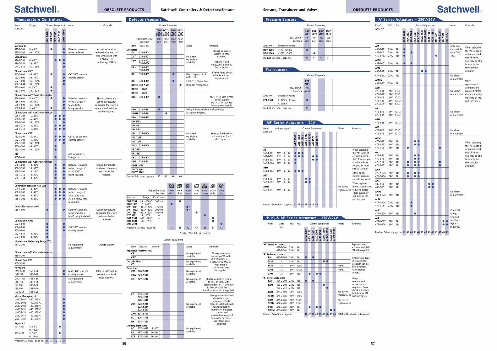
Current Equipment
DDP DDP DDP DDP5601 5610 6601 6610
LCD display no no yes yesLocation duct duct panel panel
Spec. no. Selectable range
DDP 4201 –125...+250pa
DDP 4203 –3750...+7500
Product Selection - page no. 41 41 41 41
OBSOLETE PRODUCTSSensors, Transducer and Valves
ARE
2304
ALE
130
2A
LE 1
352
ALE
S 13
02A
LES
1352
ALi
157
6A
Li 1
577
‘AE’ Series Actuators – 24V
When selectingthe ‘AL’ range ofactuators checksize of valve - youmay be able tosupply the shortstroke actuator.
Other comb-inations availableconsult Satchwell.
When replace-ment actuators arerequired pleasecheck suitability(ie) shoe or liftand lay valves.
Item/ Voltage Input Current Equipment Notes RemarksSpec. no.
AE568-1-501 24V 0...10V
568-1-502 24V 0...10V
568-1-503 24V 0...10V
568-1-504 24V 0...10V
AEH568-1-552 24V 0...10V
AES568-1-601 24V 0...10V
568-1-602 24V 0...10V
AEHS No direct568-1-651 24V 0...10V replacement
Product Selection - page no. 47 48 48 48 48 48 48
Item Spec Volt. Pot. Current Equipment Notes Remarksno.
'M' Series Actuators458-1-201 230V No458-1-301 230V No
'P' Series ActuatorsPM 453-1-203 230V No
SPM – 230V No
EPM 31 24V 1000Ω N.D.R.
ZPM 31 24V 135Ω N.D.R.
XPM 31 24V No
'K' Series ActuatorsKM 454-2-202 230V No
SKM 455-2-202 230V No 455-2-252 230V No
EKM 475-2-401 24V 1000Ω No direct
SEKM 484-2-401 24V 1000Ω replacement
ZKM 475-2-201 24V 135Ω No directSZKM 484-2-201 24V 135Ω replacement
XKM 474-2-201 24V No SXKM 483-2-201 24V No
Product Selection - page no. 47 47 48 48 48 48 48 48 48 N.D.R.= No direct replacement
‘P, K, & M’ Series Actuators – 230V/24V
ARM
260
7A
RX
220
3A
LM 1
601
ALX
120
1A
LX 1
251
ALM
S 16
01A
LMS
1651
ALX
S 12
01A
LXS
1251
Replace valveactuator with MB/ARM linkage kit.
Check valve typeif replacementactuator can befitted withoutvalve changeas well.
Whenreplacementactuators arerequired pleasecheck suitability(ie) shoe or liftand lay valves.
Item/ Volt. Pot. Current Equipment Notes RemarksSpec. no.
AM ARM not456-2-201 230V No compatible456-2-401 230V No with CMC456-2-402 230V No 3803
AMH457-2-451 230V No
AMS457-2-201 230V No
457-2-202 230V No No direct
AMHS replacement
457-2-251 230V No
AZM476-1-401 24V 135Ω No direct476-1-402 24V 135Ω replacement476-1-451 24V 135Ω476-1-801 24V 135Ω476-1-851 24V 135Ω
AZ476-2-401 24V 135Ω No direct476-2-451 24V 135Ω replacement
AZH476-2-851 24V 135Ω
AZS476-2-401 24V 135Ω No direct476-2-451 24V 135Ω replacement
AXM476-1-201 24V No
476-1-202 24V No
476-1-251 24V No
AX476-2-701 24V No
476-2-751 24V No
476-2-201 24V No
476-2-251 24V No
AXH476-2-276 24V No
476-2-776 24V No
AXS485-2-201 24V No
485-2-251 24V No
AXHS No direct485-2-276 24V No replacement
ALM477-1-626 230V No
477-1-651 230V No
ALX Check VA477-1-226 24V No rating.
ALE Check if
477-1-327 24V No feedback
477-1-376 24V No signal isrequired.
Product Select. - page no. 47 47 48 48 48 48 48 48 48 47 47 48 48
ARM
260
7A
RX
220
3A
LM 1
601
ALX
120
1A
LX 1
251
ALM
S 16
01A
LMS
1651
ALX
S 12
01A
LXS
1251
RM
360
1X
RM
320
1A
Li 1
576
ALi
157
7
‘A’ Series Actuators – 230V/24V
When selectingthe ‘AL’ range ofactuators checksize of valve -you may be ableto supply theshort strokeactuator.
Whenreplacementactuators arerequired pleasecheck suitability(ie) shoe or liftand lay valves.
When selectingthe ‘AL’ range ofactuators checksize of valve -you may be ableto supply theshort strokeactuator.
Pressure Sensors
Current Equipment
EPT7401
LCD display yesLocation panel
Spec. no. Selectable range
EPT 7301 0...10Vdc, 0...5Vdc,
4...20mA
Product Selection - page no. 45
Transducers
57
Current Equipment
DDH DDTH DRH DRTH7XXX 7XXX 7XXX 7XXX8XXX 8XXX 8XXX 8XXX
Adjustable scale none none none noneLocation duct duct room room
Item Spec. no. Notes Remarks
DetectorsEH 331-1-401
ZHT 331-2-601 No direct
DDH 331-3-702 equivalent
331-3-704 available
DRH 331-3-601331-3-602
DRH 331-3-401 Direct replacementABC = 123
DRH 331-4-401 Change terminal nos.
DRTH 331-7-501 Requires remounting
DRTH 7722
DRTH 7723
DDH 331-3-451
DDH 331-7-451 Fixing is the same but enclosure size
DDTH 331-7-551 is slightly different.
DDH 331-3-551
DO 2202
DD 1401
DD 1403
DD 336-1-204 No direct
DW 1202 equivalent
DW 1204available
DWS 339-1-304
DR 3251
DR 3252
DRT 215-1-601
DDE 331-3-301
DDTE 1601
DWTE 1201DWTE 1202
Product Selection - page no. 41 41 40 40
56
Item/ Range Current Equipment Notes RemarksSpec. no.
Intronic X575-1-201 6...40°C Detectors/sensors575-1-202 40...110°C to be replaced
Monotronic574-2-551 6...40°C
574-2-552 20...95°C
574-2-553 45...125°C
Climatronic CXT562-3-601 –5...40°C CXT 5605 can use562-3-602 20...70°C existing sensors562-3-603 35...120°C
562-3-604 35...120°C
562-4-601 0...50°C
562-4-604 30...120°C
Climatronic AXT Controller-motor566-1-601 5...40°C Detectors/sensors566-1-602 20...65°C to be changed if566-1-603 35...120°C MMC, KMC is566-1-651 5...40°C being installed
Climatronic AZT Controller-motor566-1-301 –5...40°C
566-1-302 –5...40°C
566-1-303 35...120°C
566-1-351 –5...40°C
566-1-352 –5...40°C
Climatronic CZT562-3-301 –5...40°C CZT 5305 can use562-3-302 –5...40°C existing sensors562-3-303 35...120°C
562-4-302 –5...40°C
562-4-303 30...120°C
CD ARE actuator +567-2-401 linkage kit
Climatronic AZT Controller-motor566-3-001 10...35°C Detectors/sensors566-3-302 10...35°C to be changed if566-3-304 10...35°C MMC, KMC is566-3-352 10...35°C being installed.566-3-354 10...35°C
Controller-actuator AET, AEST568-1-201 10...40°C Detectors/sensors568-1-202 10...40°C to be changed if568-1-301 10...40°C adjustable type.568-1-302 10...40°C Also if MMC, KMC
is installed.
Controller-motor AXR566-1-801 Detectors/sensors
to be changed ifMMC being installed.
Climatronic CXR 562-1-801
562-2-801 CXR 5805 can use562-3-801 existing sensors562-4-831 10...40°C
562-4-801 10...40°C
Monotronic Balancing Relay (ZC)581-2-201 No equivalent
replacement
Climatronic AZS Controller-motor485-1-201
Climatronic CZS562-3-201
KeyboardCMT 1201 563-1-201 MMC 4701 can useFMS 1201 583-1-201 existing sensors
MPD 1801 583-1-801 No equivalent COE 1601 583-1-601 replacementsFSS 1001 583-1-001FSS 1401 583-1-401FSC 1251 583-1-251
Micro ManagementMMC 2401 –40...140°C
MMC 2402 –40...140°C
MMC 2403 –40...140°C
MMC 2451 –40...150°C
MMC 2452 –40...150°C
MMC 2453 –40...150°C
MMC 3701 –40...150°C
KeyboardKZT 4351 5...50°C
0...10VdcKET 4201 5...50°C
0...10Vdc
Product Selection - page no. 35 36 36 36 37
Actuators must bereplaced with a 0...10Vtype when used with
CZT/KMC ormulti-stage MMC’s.
These controls arecontroller/actuator
combined therefore areplacement actuator
will be required.
Controller/actuatorcombined therefore
actuator to bereplaced.
Controller/actuatorcombined therefore
actuator to bereplaced.
Change system.
Refer to Satchwell orcontact your local
sales engineer.
CX
R 5
805
CX
T 56
05
CZT
530
5
KM
C 3
201
MM
C 4
701
Temperature Controllers
Current Equipment
Item Spec. no. Range Notes Remarks
Regulator ThermostatsCR No equivalent
CRX available
Outside Pilot No equivalentCP available
DetectorsC7P 326-2-501 No equivalent
C7W 323-2-501 available
CO 327-1-202 No equivalentavailable
ET 325-1-201325-1-251325-1-301
ZW 323-2-201 No equivalent323-2-204 available323-2-207
ZHO 331-2-701
EO 326-1-303
DP 334-1-201
Limiting DetectorsLO 137-1-452 5...60°C No equivalent
LR 167-1-253 20...90°C available
LZS 315-1-201 10...40°C
Change completesystem to CSC withdetectors/sensors.
If actuator is XKM orXPM then a
transformer mustbe supplied.
Detectors/sensors
Refer to Satchwell orcontact your local
sales engineer.
DDH 3451 uses 15Vdcpower supply
DDTH 7551 requires24Vac power supply.
Change control systemdependant uponexisting controls.
Refer to Satchwell withfull specification
number of obsoletecontrol and
temperature range ofcontroller or contact
your local salesengineer.
Change complete system to CSC or MMC with
detectors/sensors. If actuatoris XKM or XPM then a
transformer must be supplied.
Change completesystem to KMC
or MMC.
Actuators anddetectors/sensors to
be replaced.
If valve fitted checksuitable actuator
replacement.
DDU DDT DWT DWT DST DOT DOS1803 0001 0001 0002 0001 0002 0001
Adjustable scale none none none none none none noneLocation duct duct imm. imm. clamp outs. outs.
Spec. no. Range Stem/pocket
DDT 1701 –5...+100°C 300mm DDU 1801 –5...+40°C – DWT 1701 –10...+120°C 125mm *DWT 1702 –10...+120°C 200mm *DWT 1801 –10...+120°C 165mm DST 1601 5...120°C – DOT 2301 –40...+40°C – DOT 0001 –40...+55°C – DOS 2501 – –
Product Selection - page no. 41 41 42 42 42 43 43
* note: DWA 0001 is required
OBSOLETE PRODUCTS Satchwell Controllers & Detectors/Sensors
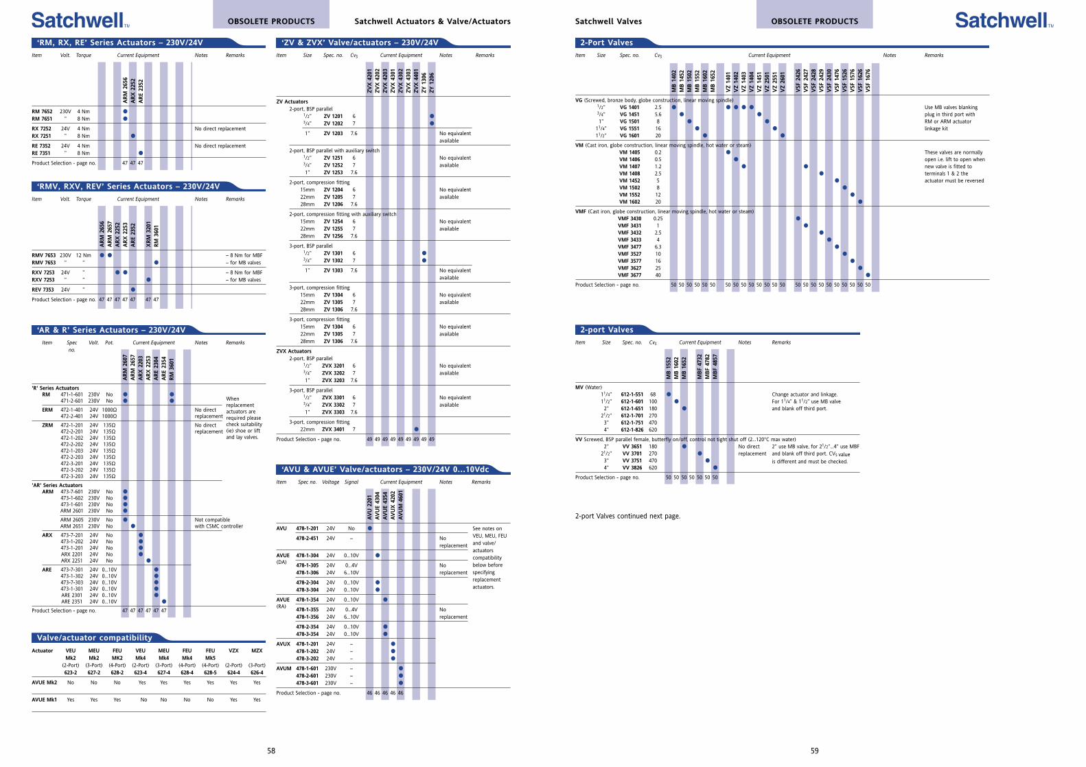
59
OBSOLETE PRODUCTSSatchwell Valves
Item Size Spec. no. CvS Current Equipment Notes Remarks
VG (Screwed, bronze body, globe construction, linear moving spindle)1/2” VG 1401 2.5 Use MB valves blanking3/4” VG 1451 5.6 plug in third port with1” VG 1501 8 RM or ARM actuator
11/4” VG 1551 16 linkage kit11/2” VG 1601 20
VM (Cast iron, globe construction, linear moving spindle, hot water or steam)VM 1405 0.2 These valves are normallyVM 1406 0.5 open i.e. lift to open whenVM 1407 1.2 new valve is fitted toVM 1408 2.5 terminals 1 & 2 the VM 1452 5 actuator must be reversedVM 1502 8
VM 1552 12
VM 1602 20
VMF (Cast iron, globe construction, linear moving spindle, hot water or steam)VMF 3430 0.25
VMF 3431 1
VMF 3432 2.5
VMF 3433 4
VMF 3477 6.3
VMF 3527 10
VMF 3577 16
VMF 3627 25
VMF 3677 40
Product Selection - page no. 50 50 50 50 50 50 50 50 50 50 50 50 50 50 50 50 50 50 50 50 50 50 50 50
MB 1
402
MB 1
452
MB 1
502
MB 1
552
MB 1
602
MB 1
652
VZ
1401
VZ
1402
VZ
1403
VZ
1404
VZ
1451
VZ
2501
VZ
2551
VZ
2601
VSF
242
6V
SF 2
427
VSF
242
8V
SF 2
429
VSF
243
0V
SF 1
476
VSF
152
6V
SF 1
576
VSF
162
6V
SF 1
676
2-Port Valves
Item Size Spec. no. CvS Current Equipment Notes Remarks
MV (Water)11/4” 612-1-551 68 Change actuator and linkage.11/2” 612-1-601 100 For 11/4” & 11/2” use MB valve 2” 612-1-651 180 and blank off third port.
21/2” 612-1-701 2703” 612-1-751 4704” 612-1-826 620
VV Screwed, BSP parallel female, butterfly on/off, control not tight shut off (2...120°C max water)2” VV 3651 180 No direct 2” use MB valve, for 21/2”...4” use MBF
21/2” VV 3701 270 replacement and blank off third port. CVS value 3” VV 3751 470 is different and must be checked.4” VV 3826 620
Product Selection - page no. 50 50 50 50 50 50 50
2-port Valves
MB 1
552
MB 1
602
MB 1
652
MBF
4732
MBF
4782
MBF
4857
2-port Valves continued next page.
Item Spec Volt. Pot. Current Equipment Notes Remarksno.
'R' Series ActuatorsRM 471-1-601 230V No
471-2-601 230V No
ERM 472-1-401 24V 1000Ω No direct472-2-401 24V 1000Ω replacement
ZRM 472-1-201 24V 135Ω No direct472-2-201 24V 135Ω replacement472-1-202 24V 135Ω472-2-202 24V 135Ω472-1-203 24V 135Ω472-2-203 24V 135Ω472-3-201 24V 135Ω472-3-202 24V 135Ω472-3-203 24V 135Ω
'AR' Series ActuatorsARM 473-7-601 230V No
473-1-602 230V No 473-1-601 230V No ARM 2601 230V No
ARM 2605 230V No Not compatibleARM 2651 230V No with CSMC controller
ARX 473-7-201 24V No 473-1-202 24V No 473-1-201 24V No ARX 2201 24V No ARX 2251 24V No
ARE 473-7-301 24V 0...10V 473-1-302 24V 0...10V 473-7-303 24V 0...10V 473-1-301 24V 0...10V ARE 2301 24V 0...10V ARE 2351 24V 0...10V
Product Selection - page no. 47 47 47 47 47 47
ARM
260
7A
RM
265
7A
RX
220
3A
RX
225
3A
RE
2304
ARE
2354
RM
360
1
‘AR & R’ Series Actuators – 230V/24V
Whenreplacementactuators arerequired pleasecheck suitability(ie) shoe or liftand lay valves.
Item Spec no. Voltage Signal Current Equipment Notes Remarks
AVU 478-1-201 24V No
478-2-451 24V – No replacement
AVUE 478-1-304 24V 0...10V
(DA)478-1-305 24V 0...4V No 478-1-306 24V 6...10V replacement
478-2-304 24V 0...10V
478-3-304 24V 0...10V
AVUE 478-1-354 24V 0...10V
(RA)478-1-355 24V 0...4V No 478-1-356 24V 6...10V replacement
478-2-354 24V 0...10V
478-3-354 24V 0...10V
AVUX 478-1-201 24V –
478-1-202 24V –
478-3-202 24V –
AVUM 478-1-601 230V –
478-2-601 230V –
478-3-601 230V –
Product Selection - page no. 46 46 46 46 46
‘AVU & AVUE’ Valve/actuators – 230V/24V 0...10Vdc
AV
U 2
201
AV
UE
4304
AV
UE
4354
AV
UX
420
2AV
UM
4601
See notes onVEU, MEU, FEUand valve/actuatorscompatibilitybelow beforespecifyingreplacementactuators.
Actuator VEU MEU FEU VEU MEU FEU FEU VZX MZXMk2 Mk2 MK2 Mk4 Mk4 Mk4 Mk5
(2-Port) (3-Port) (4-Port) (2-Port) (3-Port) (4-Port) (4-Port) (2-Port) (3-Port)623-2 627-2 628-2 623-4 627-4 628-4 628-5 624-4 626-4
AVUE Mk2 No No No Yes Yes Yes Yes Yes Yes
AVUE Mk1 Yes Yes Yes No No No No Yes Yes
Valve/actuator compatibility
Item Size Spec. no. CvS Current Equipment Notes Remarks
ZV Actuators2-port, BSP parallel
1/2” ZV 1201 6 3/4” ZV 1202 7
1” ZV 1203 7.6 No equivalentavailable
2-port, BSP parallel with auxiliary switch1/2” ZV 1251 6 No equivalent3/4” ZV 1252 7 available1” ZV 1253 7.6
2-port, compression fitting15mm ZV 1204 6 No equivalent22mm ZV 1205 7 available28mm ZV 1206 7.6
2-port, compression fitting with auxiliary switch15mm ZV 1254 6 No equivalent22mm ZV 1255 7 available28mm ZV 1256 7.6
3-port, BSP parallel1/2” ZV 1301 6 3/4” ZV 1302 7
1” ZV 1303 7.6 No equivalentavailable
3-port, compression fitting15mm ZV 1304 6 No equivalent22mm ZV 1305 7 available28mm ZV 1306 7.6
3-port, compression fitting15mm ZV 1304 6 No equivalent22mm ZV 1305 7 available28mm ZV 1306 7.6
ZVX Actuators2-port, BSP parallel
1/2” ZVX 3201 6 No equivalent3/4” ZVX 3202 7 available1” ZVX 3203 7.6
3-port, BSP parallel1/2” ZVX 3301 6 No equivalent3/4” ZVX 3302 7 available1” ZVX 3303 7.6
3-port, compression fitting22mm ZVX 3401 7
Product Selection - page no. 49 49 49 49 49 49 49 49 49
‘ZV & ZVX’ Valve/actuators – 230V/24V
ZVX
420
1ZV
X 4
202
ZVX
420
3ZV
X 4
301
ZVX
430
2ZV
X 4
303
ZVX
440
1ZY
130
6ZY
120
6
58
OBSOLETE PRODUCTS Satchwell Actuators & Valve/Actuators
Item Volt. Torque Current Equipment Notes Remarks
RM 7652 230V 4 Nm
RM 7651 ” 8 Nm
RX 7252 24V 4 Nm No direct replacementRX 7251 ” 8 Nm
RE 7352 24V 4 Nm No direct replacementRE 7351 ” 8 Nm
Product Selection - page no. 47 47 47
ARM
265
6A
RX
225
2A
RE
2352
‘RM, RX, RE’ Series Actuators – 230V/24V
Item Volt. Torque Current Equipment Notes Remarks
RMV 7653 230V 12 Nm – 8 Nm for MBFRMV 7653 ” ” – for MB valves
RXV 7253 24V ” – 8 Nm for MBFRXV 7253 ” ” – for MB valves
REV 7353 24V ”
Product Selection - page no. 47 47 47 47 47 47 47
ARM
265
6A
RM
265
7A
RX
225
2A
RX
225
3A
RE
2352
XRM
320
1RM
360
1
‘RMV, RXV, REV’ Series Actuators – 230V/24V
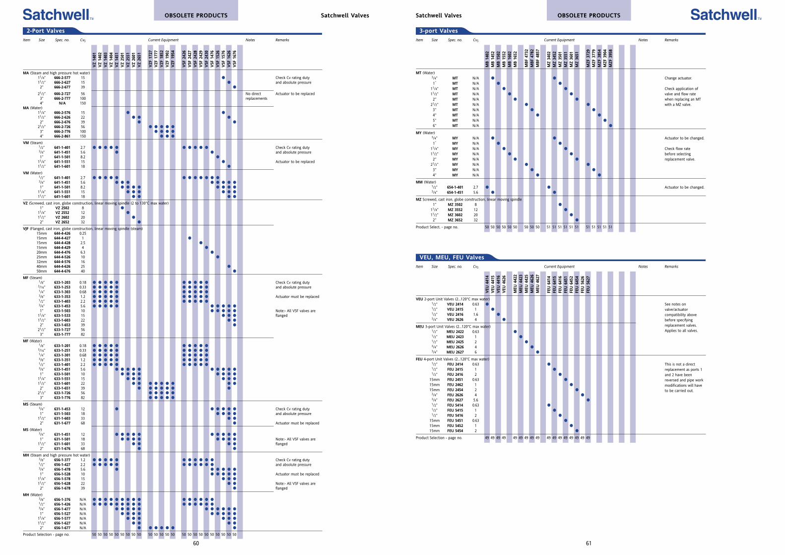
Item Size Spec. no. CvS Current Equipment Notes Remarks
VEU 2-port Unit Valves (2...120°C max water)1/2” VEU 2414 0.63 1/2” VEU 2415 1 1/2” VEU 2416 1.6 3/4” VEU 2626 4
MEU 3-port Unit Valves (2...120°C max water)1/2” MEU 2422 0.63 1/2” MEU 2423 1 1/2” MEU 2425 2 3/4” MEU 2626 4 3/4” MEU 2627 6
FEU 4-port Unit Valves (2...120°C max water)1/2” FEU 2414 0.63 1/2” FEU 2415 1 1/2” FEU 2416 2
15mm FEU 2451 0.63
15mm FEU 2462 1
15mm FEU 2454 2 3/4” FEU 2626 4 3/4” FEU 2627 5.6 1/2” FEU 5414 0.63 1/2” FEU 5415 1 1/2” FEU 5416 2
15mm FEU 5451 0.63
15mm FEU 5452 1
15mm FEU 5454 2
Product Selection - page no. 49 49 49 49 49 49 49 49 49 49 49 49 49 49 49 49 49
VEU
441
4V
EU 4
415
VEU
441
6V
EU 4
626
MEU
442
2M
EU 4
423
MEU
442
5M
EU 4
626
MEU
462
7
FEU
641
4FE
U 6
415
FEU
641
6FE
U 6
451
FEU
645
2FE
U 6
454
FEU
562
6FE
U 5
627
VEU, MEU, FEU Valves
See notes onvalve/actuatorcompatibility abovebefore specifyingreplacement valves.Applies to all valves.
This is not a directreplacement as ports 1and 2 have beenreversed and pipe workmodifications will haveto be carried out.
61
OBSOLETE PRODUCTSSatchwell Valves
Item Size Spec. no. CvS Current Equipment Notes Remarks
MT (Water)3/4” MT N/A Change actuator.1” MT N/A
11/4” MT N/A Check application of11/2” MT N/A valve and flow rate2” MT N/A when replacing an MT
21/2” MT N/A with a MZ valve.3” MT N/A
4” MT N/A
5” MT N/A
6” MT N/A
MY (Water)3/4” MY N/A Actuator to be changed.1” MY N/A
11/4” MY N/A Check flow rate11/2” MY N/A before selecting2” MY N/A replacement valve.
21/2” MY N/A
3” MY N/A
4” MY N/A
MM (Water)1/2” 654-1-401 2.7 Actuator to be changed.3/4” 654-1-451 5.6
MZ Screwed, cast iron, globe construction, linear moving spindle1” MZ 3502 8
11/4” MZ 3552 12
11/2” MZ 3602 20
2” MZ 3652 32
Product Select. - page no. 50 50 50 50 50 50 50 50 50 51 51 51 51 51 51 51 51 51 51 51
MB 1
402
MB 1
452
MB 1
502
MB 1
552
MB 1
602
MB 1
652
MBF
4732
MBF
4782
MBF
4857
MZ
3402
MZ
3452
MZ
3501
MZ
3551
MZ
3601
MZ
3651
MZF
372
9M
ZF 3
779
MZF
385
4M
ZF 3
904
MZF
395
8
3-port Valves
VZ
1401
VZ
1402
VZ
1403
VZ
1404
VZ
1451
VZ
2501
VZ
2551
VZ
2601
VZ
2651
VZF
172
7V
ZF 1
777
VZF
185
2V
ZF 1
902
VZF
195
4
VSF
242
6V
SF 2
427
VSF
242
8V
SF 2
429
VSF
243
0V
SF 1
476
VSF
152
6V
SF 1
576
VSF
162
6V
SF 1
676
2-Port Valves
Item Size Spec. no. CvS Current Equipment Notes Remarks
MA (Steam and high pressure hot water)11/4” 666-2-577 15 Check Cv rating duty11/2” 666-2-627 15 and absolute pressure2” 666-2-677 39
21/2” 666-2-727 56 No direct Actuator to be replaced3” 666-2-777 100 replacements4” N/A 150
MA (Water)11/4” 666-2-576 15 11/2” 666-2-626 22 2” 666-2-676 39
21/2” 666-2-726 56 3” 666-2-776 100 4” 666-2-861 150
VM (Steam)1/2” 641-1-401 2.7 Check Cv rating duty3/4” 641-1-451 5.6 and absolute pressure1” 641-1-501 8.2
11/4” 641-1-551 15 Actuator to be replaced11/2” 641-1-601 18
VM (Water)1/2” 641-1-401 2.7 3/4” 641-1-451 5.6 1” 641-1-501 8.2
11/4” 641-1-551 15 11/2” 641-1-601 18
VZ (Screwed, cast iron, globe construction, linear moving spindle (2 to 130°C max water)1” VZ 2502 8
11/4” VZ 2552 12 11/2” VZ 2602 20 2” VZ 2652 32
VJF (Flanged, cast iron, globe construction, linear moving spindle (steam)15mm 644-4-426 0.2515mm 644-4-427 1 15mm 644-4-428 2.5 15mm 644-4-429 4 20mm 644-4-476 6.3 25mm 644-4-526 10 32mm 644-4-576 1640mm 644-4-626 25 50mm 644-4-676 40
MF (Steam)1/8” 633-1-203 0.18 Check Cv rating duty3/16” 633-1-253 0.33 and absolute pressure1/4” 633-1-303 0.68 3/8” 633-1-353 1.2 Actuator must be replaced1/2” 633-1-403 2.2 3/4” 633-1-453 5.6 1” 633-1-503 10 Note:- All VSF valves are
11/4” 633-1-533 15 flanged11/2” 633-1-603 22 2” 633-1-653 39
21/2” 633-1-727 563” 633-1-777 82
MF (Water)1/8” 633-1-201 0.18 3/16” 633-1-251 0.33 1/4” 633-1-301 0.68 3/8” 633-1-351 1.2 1/2” 633-1-401 2.2 3/4” 633-1-451 5.6 1” 633-1-501 10
11/4” 633-1-551 15 11/2” 633-1-601 22 2” 633-1-651 39
21/2” 633-1-726 56 3” 633-1-776 82
MS (Steam)3/4” 631-1-453 12 Check Cv rating duty1” 631-1-503 18 and absolute pressure
11/2” 631-1-603 33 2” 631-1-677 68 Actuator must be replaced
MS (Water)3/4” 631-1-451 12 1” 631-1-501 18 Note:- All VSF valves are
11/2” 631-1-601 33 flanged2” 631-1-676 68
MH (Steam and high pressure hot water)3/8” 656-1-377 1.2 Check Cv rating duty1/2” 656-1-427 2.2 and absolute pressure3/4” 656-1-478 5.6 1” 656-1-528 10 Actuator must be replaced
11/4” 656-1-578 15 11/2” 656-1-628 22 Note:- All VSF valves are2” 656-1-678 39 flanged
MH (Water)3/8” 656-1-376 N/A 1/2” 656-1-426 N/A 3/4” 656-1-477 N/A 1” 656-1-527 N/A
11/4” 656-1-577 N/A 11/2” 656-1-627 N/A 2” 656-1-677 N/A
Product Selection - page no. 50 50 50 50 50 50 50 50 50 50 50 50 50 50 50 50 50 50 50 50 50 50 50 50
OBSOLETE PRODUCTS Satchwell Valves
60
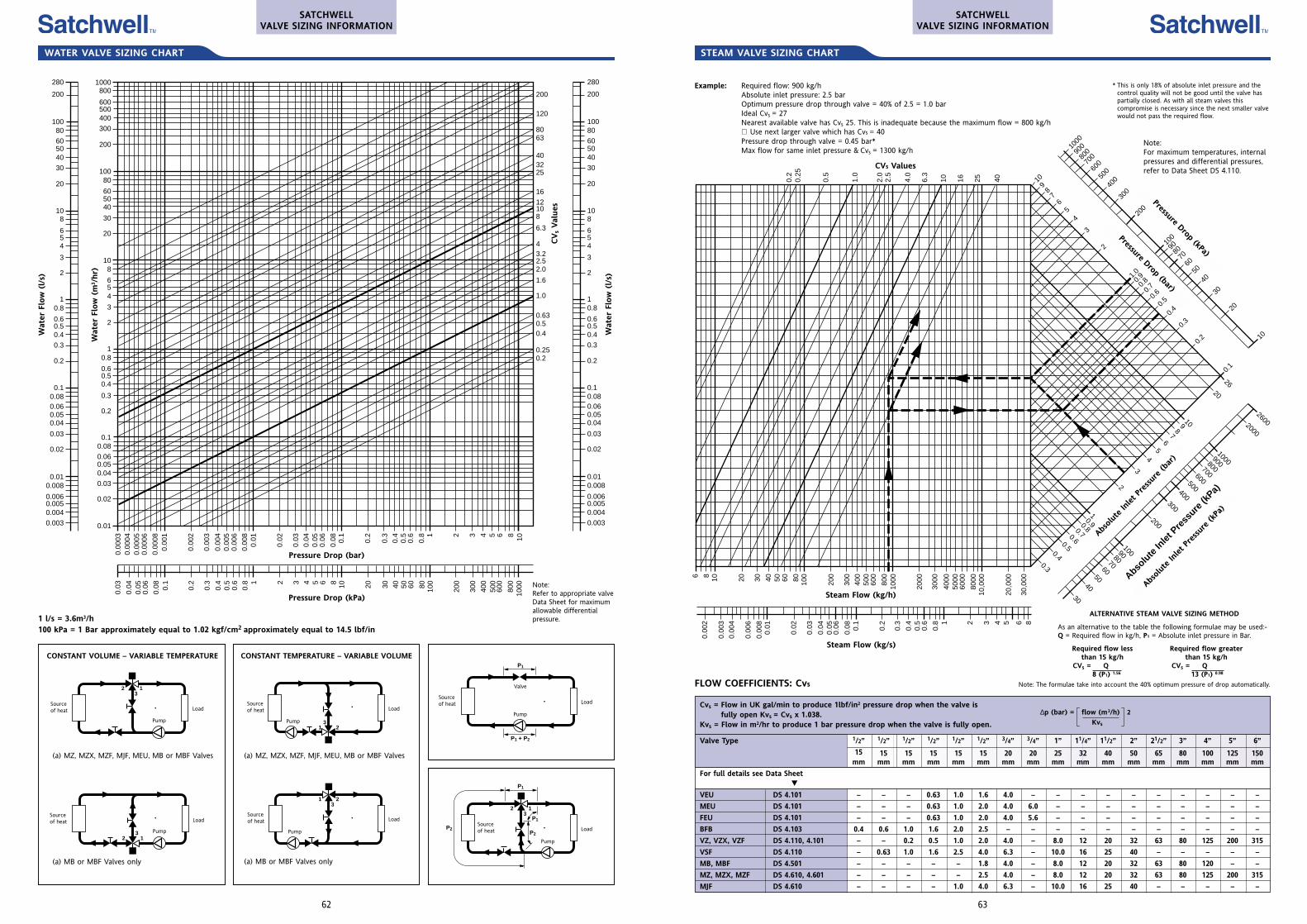
Cvs = Flow in UK gal/min to produce 1lbf/in2 pressure drop when the valve isfully open Kvs = Cvs x 1.038.
Kvs = Flow in m2/hr to produce 1 bar pressure drop when the valve is fully open.
Valve Type 1/2” 1/2” 1/2” 1/2” 1/2” 1/2” 3/4” 3/4” 1” 11/4” 11/2” 2” 21/2” 3” 4” 5” 6”
15 15 15 15 15 15 20 20 25 32 40 50 65 80 100 125 150mm mm mm mm mm mm mm mm mm mm mm mm mm mm mm mm mm
For full details see Data Sheet
VEU DS 4.101 – – – 0.63 1.0 1.6 4.0 – – – – – – – – – –
MEU DS 4.101 – – – 0.63 1.0 2.0 4.0 6.0 – – – – – – – – –
FEU DS 4.101 – – – 0.63 1.0 2.0 4.0 5.6 – – – – – – – – –
BFB DS 4.103 0.4 0.6 1.0 1.6 2.0 2.5 – – – – – – – – – – –
VZ, VZX, VZF DS 4.110, 4.101 – – 0.2 0.5 1.0 2.0 4.0 – 8.0 12 20 32 63 80 125 200 315
VSF DS 4.110 – 0.63 1.0 1.6 2.5 4.0 6.3 – 10.0 16 25 40 – – – – –
MB, MBF DS 4.501 – – – – – 1.8 4.0 – 8.0 12 20 32 63 80 120 – –
MZ, MZX, MZF DS 4.610, 4.601 – – – – – 2.5 4.0 – 8.0 12 20 32 63 80 125 200 315
MJF DS 4.610 – – – – 1.0 4.0 6.3 – 10.0 16 25 40 – – – – –
∆p (bar) = flow (m3/h) 2
Kvs
STEAM VALVE SIZING CHART
63
2620
1098
76
54
3
2
10.90.80.70.60.5
0.40.3
6 8 10 20 30 40 50 60 80 100
200
300
400
500
600
800
1000
2000
3000
4000
5000
6000
8000
10,0
00
20,0
00
30,0
00
1000
900
800
700
600
500
400
300
200
10090
8070
6050
40
30
20
10
109
87
65
4
3
2
1.00.
90.
80.
7
0.6
0.5
0.4
0.3
0.2
0.1
0.2
0.25
0.5
1.0
2.0
2.5
4.0
6.3
10 16 25 40
0.00
2
0.00
3
0.00
4
0.00
6
0.00
80.
01
0.02
0.03
0.04
0.05
0.06
0.08 0.1
0.2
0.3
0.4
0.5
0.6
0.8 1 2 3 4 5 6 8
26002000
1000900800700600500400300
200
1009080706050
4030
Pressure Drop (kPa)
Pressure Drop (bar)
Absolu
te In
let P
ress
ure (b
ar)
Absolu
te In
let P
ress
ure (k
Pa)
FLOW COEFFICIENTS: Cvs
Example: Required flow: 900 kg/hAbsolute inlet pressure: 2.5 barOptimum pressure drop through valve = 40% of 2.5 = 1.0 barIdeal Cvs = 27Nearest available valve has Cvs 25. This is inadequate because the maximum flow = 800 kg/h∴ Use next larger valve which has Cvs = 40Pressure drop through valve = 0.45 bar*Max flow for same inlet pressure & Cvs = 1300 kg/h
* This is only 18% of absolute inlet pressure and the control quality will not be good until the valve has partially closed. As with all steam valves this compromise is necessary since the next smaller valve would not pass the required flow.
Note:For maximum temperatures, internalpressures and differential pressures,refer to Data Sheet DS 4.110.
CVs Values
Steam Flow (kg/h)
Steam Flow (kg/s)
ALTERNATIVE STEAM VALVE SIZING METHOD
As an alternative to the table the following formulae may be used:-Q = Required flow in kg/h, P1 = Absolute inlet pressure in Bar.
Required flow lessthan 15 kg/h
CVs = Q8 (P1) 1.56
Required flow greaterthan 15 kg/h
CVs = Q13 (P1) 0.98
Note: The formulae take into account the 40% optimum pressure of drop automatically.
Pressure Drop (kPa)
Pressure Drop (bar)
Abso
lute
Inlet P
ressur
e (b
ar)
Abso
lute
Inlet P
ressur
e (k
Pa)
SATCHWELLVALVE SIZING INFORMATION
2 13
WATER VALVE SIZING CHART
62
P1
P1 + P2
2 13
P1
P2
P1
P22 1
3
213
213
1000800
600500400
300
200
10080
605040
30
20
108
654
3
2
10.8
0.60.50.4
0.3
0.2
0.10.08
0.060.050.04
0.03
0.02
0.01
200
120
8063
403225
16
12108
6.3
43.22.52.0
1.6
1.0
0.630.50.4
0.250.2
280
200
10080
605040
30
20
108
654
3
2
10.8
0.60.50.4
0.3
0.2
0.10.080.060.050.04
0.03
0.02
0.010.008
0.0060.0050.004
0.003
280
200
10080
605040
30
20
108
654
3
2
10.8
0.60.50.4
0.3
0.2
0.10.080.060.050.04
0.03
0.02
0.010.008
0.0060.0050.004
0.003
0.00
030.
0004
0.00
050.
0006
0.00
080.
001
0.00
2
0.00
3
0.00
40.
005
0.00
6
0.00
80.
01
0.02
0.03
0.04
0.05
0.06
0.08 0.1
0.2
0.3
0.4
0.5
0.6
0.8 1 2 3 4 5 6 8 10
0.03
0.04
0.05
0.06
0.08 0.1
0.2
0.3
0.4
0.5
0.6
0.8 1 2 3 4 5 6 8 10 20 30 40 50 60 80 100
200
300
400
500
600
800
1000
Pressure Drop (bar)
Pressure Drop (kPa)
Note:Refer to appropriate valveData Sheet for maximumallowable differentialpressure.1 l/s = 3.6m3/h
100 kPa = 1 Bar approximately equal to 1.02 kgf/cm2 approximately equal to 14.5 lbf/in
CONSTANT VOLUME – VARIABLE TEMPERATURE CONSTANT TEMPERATURE – VARIABLE VOLUME
(a) MZ, MZX, MZF, MJF, MEU, MB or MBF Valves
Sourceof heat
Sourceof heat
Sourceof heat
(a) MZ, MZX, MZF, MJF, MEU, MB or MBF Valves
Load
Load
Load
LoadSourceof heat
Sourceof heat
Load
Load
(a) MB or MBF Valves only(a) MB or MBF Valves only
Sourceof heat
Pump
PumpPump
Pump
Valve
Pump Pump
Wat
er F
low
(l/
s)
Wat
er F
low
(m
3 /hr)
CV
sVal
ues
Wat
er F
low
(l/
s)
SATCHWELLVALVE SIZING INFORMATION
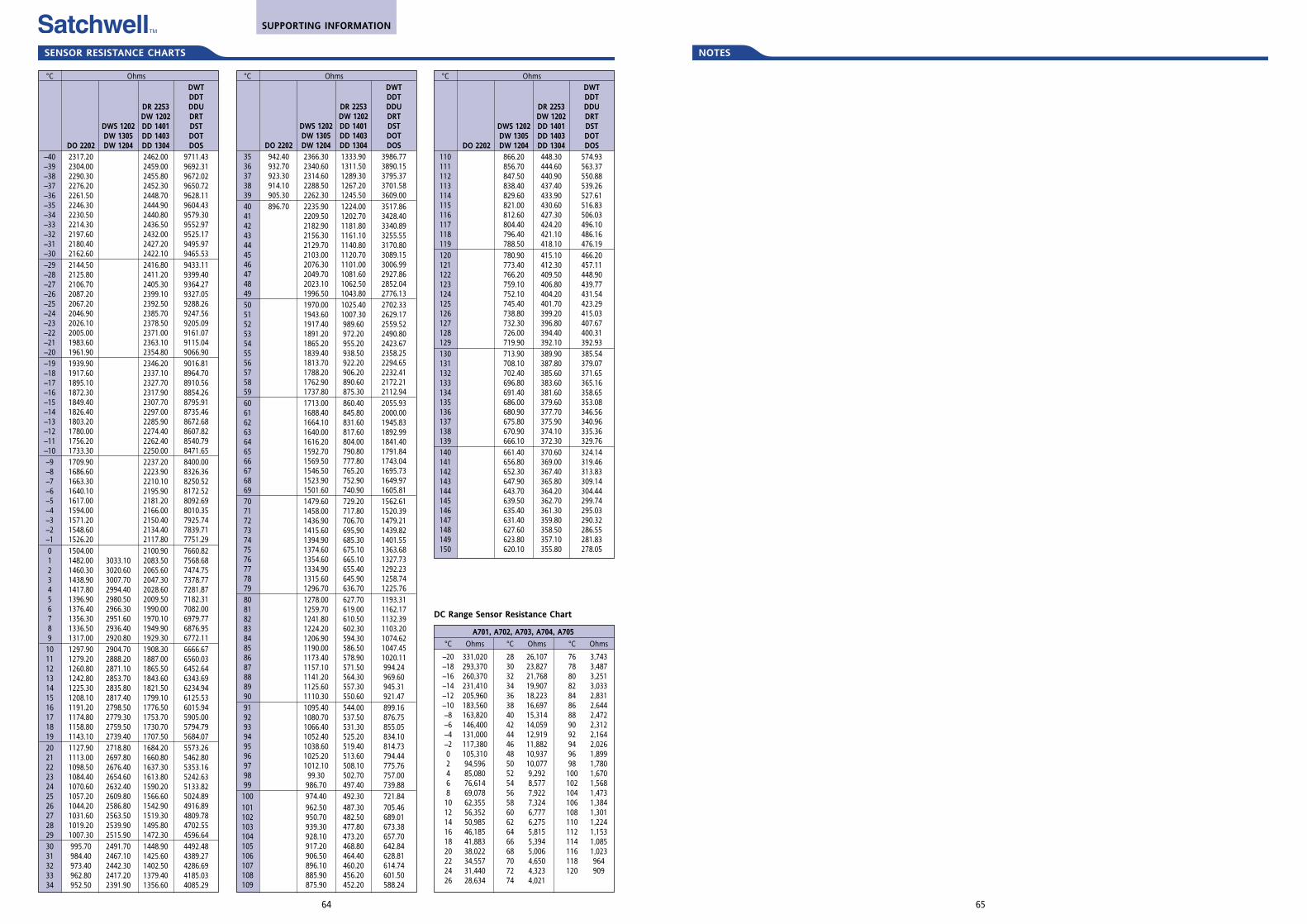
NOTES
65
°C OhmsDWTDDT
DR 2253 DDUDW 1202 DRT
DWS 1202 DD 1401 DSTDW 1305 DD 1403 DOT
DO 2202 DW 1204 DD 1304 DOS35 942.40 2366.30 1333.90 3986.7736 932.70 2340.60 1311.50 3890.1537 923.30 2314.60 1289.30 3795.3738 914.10 2288.50 1267.20 3701.5839 905.30 2262.30 1245.50 3609.0040 896.70 2235.90 1224.00 3517.8641 2209.50 1202.70 3428.4042 2182.90 1181.80 3340.8943 2156.30 1161.10 3255.5544 2129.70 1140.80 3170.8045 2103.00 1120.70 3089.1546 2076.30 1101.00 3006.9947 2049.70 1081.60 2927.8648 2023.10 1062.50 2852.0449 1996.50 1043.80 2776.1350 1970.00 1025.40 2702.3351 1943.60 1007.30 2629.1752 1917.40 989.60 2559.5253 1891.20 972.20 2490.8054 1865.20 955.20 2423.6755 1839.40 938.50 2358.2556 1813.70 922.20 2294.6557 1788.20 906.20 2232.4158 1762.90 890.60 2172.2159 1737.80 875.30 2112.9460 1713.00 860.40 2055.9361 1688.40 845.80 2000.0062 1664.10 831.60 1945.8363 1640.00 817.60 1892.9964 1616.20 804.00 1841.4065 1592.70 790.80 1791.8466 1569.50 777.80 1743.0467 1546.50 765.20 1695.7368 1523.90 752.90 1649.9769 1501.60 740.90 1605.8170 1479.60 729.20 1562.6171 1458.00 717.80 1520.3972 1436.90 706.70 1479.2173 1415.60 695,90 1439.8274 1394.90 685.30 1401.5575 1374.60 675.10 1363.6876 1354.60 665.10 1327.7377 1334.90 655.40 1292.2378 1315.60 645.90 1258.7479 1296.70 636.70 1225.7680 1278.00 627.70 1193.3181 1259.70 619.00 1162.1782 1241.80 610.50 1132.3983 1224.20 602.30 1103.2084 1206.90 594.30 1074.6285 1190.00 586.50 1047.4586 1173.40 578.90 1020.1187 1157.10 571.50 994.2488 1141.20 564.30 969.6089 1125.60 557.30 945.3190 1110.30 550.60 921.4791 1095.40 544.00 899.1692 1080.70 537.50 876.7593 1066.40 531.30 855.0594 1052.40 525.20 834.1095 1038.60 519.40 814.7396 1025.20 513.60 794.4497 1012.10 508.10 775.7698 99.30 502.70 757.0099 986.70 497.40 739.88100 974.40 492.30 721.84101 962.50 487.30 705.46102 950.70 482.50 689.01103 939.30 477.80 673.38104 928.10 473.20 657.70105 917.20 468.80 642.84106 906.50 464.40 628.81107 896.10 460.20 614.74108 885.90 456.20 601.50109 875.90 452.20 588.24
SENSOR RESISTANCE CHARTS
64
°C Ohms
–20 331,020–18 293,370–16 260,370–14 231,410–12 205,960–10 183,560–8 163,820–6 146,400–4 131,000–2 117,3800 105,3102 94,5964 85,0806 76,6148 69,07810 62,35512 56,35214 50,98516 46,18518 41,88320 38,02222 34,55724 31,44026 28,634
°C Ohms
28 26,10730 23,82732 21,76834 19,90736 18,22338 16,69740 15,31442 14,05944 12,91946 11,88248 10,93750 10,07752 9,29254 8,57756 7,92258 7,32460 6,77762 6,27564 5,81566 5,39468 5,00670 4,65072 4,32374 4,021
°C Ohms
76 3,74378 3,48780 3,25182 3,03384 2,83186 2,64488 2,47290 2,31292 2,16494 2,02696 1,89998 1,780100 1,670102 1,568104 1,473106 1,384108 1,301110 1,224112 1,153114 1,085116 1,023118 964120 909
DC Range Sensor Resistance Chart
°C OhmsDWTDDT
DR 2253 DDUDW 1202 DRT
DWS 1202 DD 1401 DSTDW 1305 DD 1403 DOT
DO 2202 DW 1204 DD 1304 DOS–40 2317.20 2462.00 9711.43–39 2304.00 2459.00 9692.31–38 2290.30 2455.80 9672.02–37 2276.20 2452.30 9650.72–36 2261.50 2448.70 9628.11–35 2246.30 2444.90 9604.43–34 2230.50 2440.80 9579.30–33 2214.30 2436.50 9552.97–32 2197.60 2432.00 9525.17–31 2180.40 2427.20 9495.97–30 2162.60 2422.10 9465.53–29 2144.50 2416.80 9433.11–28 2125.80 2411.20 9399.40–27 2106.70 2405.30 9364.27–26 2087.20 2399.10 9327.05–25 2067.20 2392.50 9288.26–24 2046.90 2385.70 9247.56–23 2026.10 2378.50 9205.09–22 2005.00 2371.00 9161.07–21 1983.60 2363.10 9115.04–20 1961.90 2354.80 9066.90–19 1939.90 2346.20 9016.81–18 1917.60 2337.10 8964.70–17 1895.10 2327.70 8910.56–16 1872.30 2317.90 8854.26–15 1849.40 2307.70 8795.91–14 1826.40 2297.00 8735.46–13 1803.20 2285.90 8672.68–12 1780.00 2274.40 8607.82–11 1756.20 2262.40 8540.79–10 1733.30 2250.00 8471.65–9 1709.90 2237.20 8400.00–8 1686.60 2223.90 8326.36–7 1663.30 2210.10 8250.52–6 1640.10 2195.90 8172.52–5 1617.00 2181.20 8092.69–4 1594.00 2166.00 8010.35–3 1571.20 2150.40 7925.74–2 1548.60 2134.40 7839.71–1 1526.20 2117.80 7751.290 1504.00 2100.90 7660.821 1482.00 3033.10 2083.50 7568.682 1460.30 3020.60 2065.60 7474.753 1438.90 3007.70 2047.30 7378.774 1417.80 2994.40 2028.60 7281.875 1396.90 2980.50 2009.50 7182.316 1376.40 2966.30 1990.00 7082.007 1356.30 2951.60 1970.10 6979.778 1336.50 2936.40 1949.90 6876.959 1317.00 2920.80 1929.30 6772.1110 1297.90 2904.70 1908.30 6666.6711 1279.20 2888.20 1887.00 6560.0312 1260.80 2871.10 1865.50 6452.6413 1242.80 2853.70 1843.60 6343.6914 1225.30 2835.80 1821.50 6234.9415 1208.10 2817.40 1799.10 6125.5316 1191.20 2798.50 1776.50 6015.9417 1174.80 2779.30 1753.70 5905.0018 1158.80 2759.50 1730.70 5794.7919 1143.10 2739.40 1707.50 5684.0720 1127.90 2718.80 1684.20 5573.2621 1113.00 2697.80 1660.80 5462.8022 1098.50 2676.40 1637.30 5353.1623 1084.40 2654.60 1613.80 5242.6324 1070.60 2632.40 1590.20 5133.8225 1057.20 2609.80 1566.60 5024.8926 1044.20 2586.80 1542.90 4916.8927 1031.60 2563.50 1519.30 4809.7828 1019.20 2539.90 1495.80 4702.5529 1007.30 2515.90 1472.30 4596.6430 995.70 2491.70 1448.90 4492.4831 984.40 2467.10 1425.60 4389.2732 973.40 2442.30 1402.50 4286.6933 962.80 2417.20 1379.40 4185.0334 952.50 2391.90 1356.60 4085.29
°C OhmsDWTDDT
DR 2253 DDUDW 1202 DRT
DWS 1202 DD 1401 DSTDW 1305 DD 1403 DOT
DO 2202 DW 1204 DD 1304 DOS110 866.20 448.30 574.93111 856.70 444.60 563.37112 847.50 440.90 550.88113 838.40 437.40 539.26114 829.60 433.90 527.61115 821.00 430.60 516.83116 812.60 427.30 506.03117 804.40 424.20 496.10118 796.40 421.10 486.16119 788.50 418.10 476.19120 780.90 415.10 466.20121 773.40 412.30 457.11122 766.20 409.50 448.90123 759.10 406.80 439.77124 752.10 404.20 431.54125 745.40 401.70 423.29126 738.80 399.20 415.03127 732.30 396.80 407.67128 726.00 394.40 400.31129 719.90 392.10 392.93130 713.90 389.90 385.54131 708.10 387.80 379.07132 702.40 385.60 371.65133 696.80 383.60 365.16134 691.40 381.60 358.65135 686.00 379.60 353.08136 680.90 377.70 346.56137 675.80 375.90 340.96138 670.90 374.10 335.36139 666.10 372.30 329.76140 661.40 370.60 324.14141 656.80 369.00 319.46142 652.30 367.40 313.83143 647.90 365.80 309.14144 643.70 364.20 304.44145 639.50 362.70 299.74146 635.40 361.30 295.03147 631.40 359.80 290.32148 627.60 358.50 286.55149 623.80 357.10 281.83150 620.10 355.80 278.05
A701, A702, A703, A704, A705
SUPPORTING INFORMATION
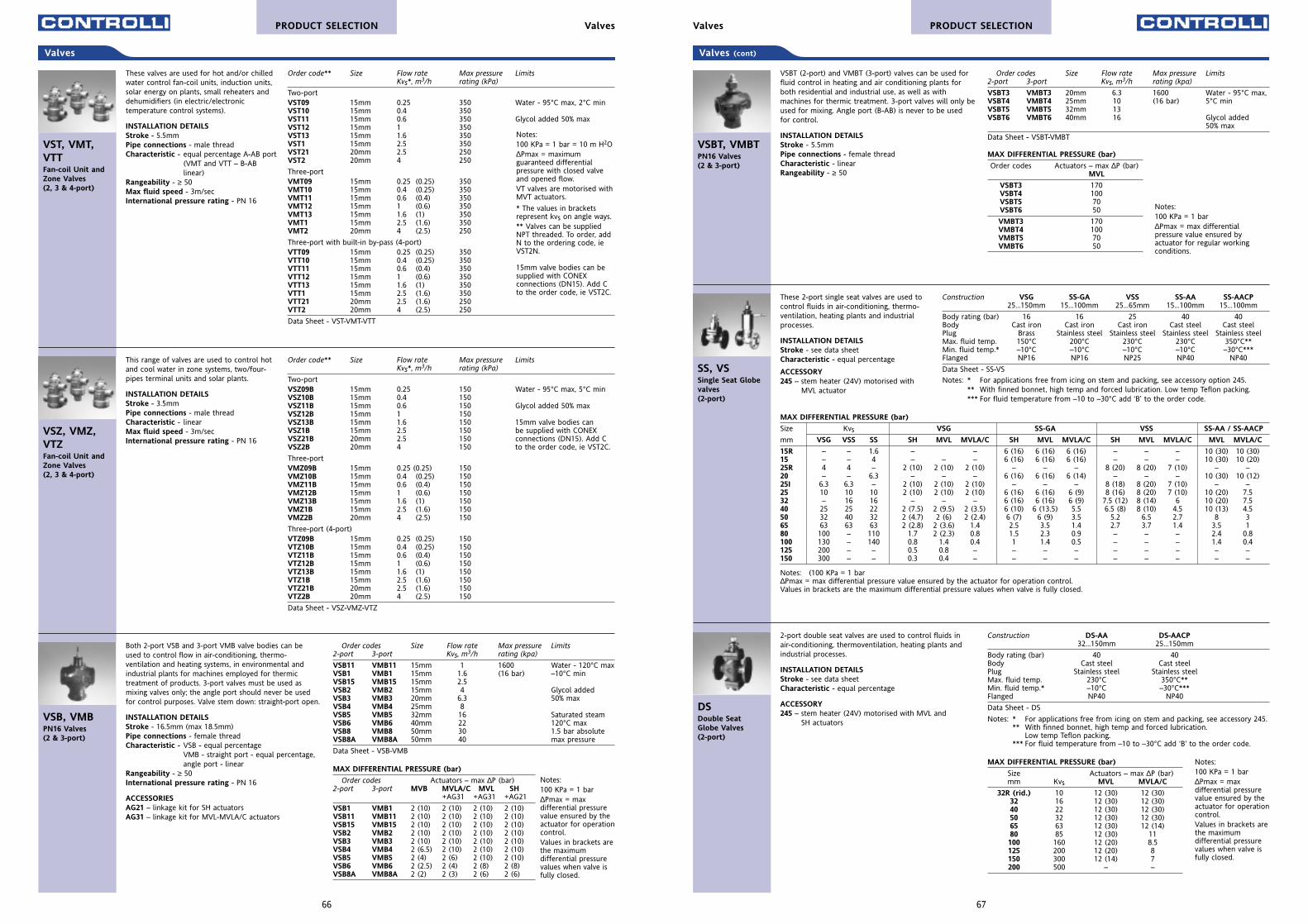
67
Valves (cont)
Order codes Size Flow rate Max pressure Limits2-port 3-port Kvs, m3/h rating (kpa)
VSBT3 VMBT3 20mm 6.3 1600 Water - 95°C max,VSBT4 VMBT4 25mm 10 (16 bar) 5°C minVSBT5 VMBT5 32mm 13 VSBT6 VMBT6 40mm 16 Glycol added
50% max
Data Sheet - VSBT-VMBT
VSBT (2-port) and VMBT (3-port) valves can be used forfluid control in heating and air conditioning plants forboth residential and industrial use, as well as withmachines for thermic treatment. 3-port valves will only beused for mixing. Angle port (B-AB) is never to be usedfor control.
INSTALLATION DETAILSStroke - 5.5mmPipe connections - female threadCharacteristic - linearRangeability - ≥ 50
VSBT, VMBTPN16 Valves(2 & 3-port)
MAX DIFFERENTIAL PRESSURE (bar)
Order codes Actuators – max ∆P (bar) MVL
VSBT3 170VSBT4 100VSBT5 70VSBT6 50
VMBT3 170VMBT4 100VMBT5 70VMBT6 50
Notes: 100 KPa = 1 bar∆Pmax = max differentialpressure value ensured byactuator for regular workingconditions.
Construction DS-AA DS-AACP32...150mm 25...150mm
Body rating (bar) 40 40Body Cast steel Cast steelPlug Stainless steel Stainless steelMax. fluid temp. 230°C 350°C**Min. fluid temp.* –10°C –30°C***Flanged NP40 NP40
Data Sheet - DS
Notes: * For applications free from icing on stem and packing, see accessory 245.** With finned bonnet, high temp and forced lubrication.
Low temp Teflon packing.*** For fluid temperature from –10 to –30°C add ‘B’ to the order code.
2-port double seat valves are used to control fluids inair-conditioning, thermoventilation, heating plants andindustrial processes.
INSTALLATION DETAILSStroke - see data sheetCharacteristic - equal percentage
ACCESSORY245 – stem heater (24V) motorised with MVL and
SH actuators
DSDouble Seat Globe Valves(2-port)
MAX DIFFERENTIAL PRESSURE (bar)
Size Actuators – max ∆P (bar) mm Kvs MVL MVLA/C
32R (rid.) 10 12 (30) 12 (30)32 16 12 (30) 12 (30)40 22 12 (30) 12 (30)50 32 12 (30) 12 (30)65 63 12 (30) 12 (14)80 85 12 (30) 11100 160 12 (20) 8.5125 200 12 (20) 8150 300 12 (14) 7200 500 – –
Notes:100 KPa = 1 bar ∆Pmax = maxdifferential pressurevalue ensured by theactuator for operationcontrol.Values in brackets arethe maximumdifferential pressurevalues when valve isfully closed.
Construction VSG SS-GA VSS SS-AA SS-AACP25...150mm 15...100mm 25...65mm 15...100mm 15...100mm
Body rating (bar) 16 16 25 40 40Body Cast iron Cast iron Cast iron Cast steel Cast steelPlug Brass Stainless steel Stainless steel Stainless steel Stainless steelMax. fluid temp. 150°C 200°C 230°C 230°C 350°C**Min. fluid temp.* –10°C –10°C –10°C –10°C –30°C***Flanged NP16 NP16 NP25 NP40 NP40
Data Sheet - SS-VS
Notes: * For applications free from icing on stem and packing, see accessory option 245.** With finned bonnet, high temp and forced lubrication. Low temp Teflon packing.*** For fluid temperature from –10 to –30°C add ‘B’ to the order code.
These 2-port single seat valves are used tocontrol fluids in air-conditioning, thermo-ventilation, heating plants and industrialprocesses.
INSTALLATION DETAILSStroke - see data sheetCharacteristic - equal percentage
ACCESSORY245 – stem heater (24V) motorised with
MVL actuator
SS, VSSingle Seat Globevalves(2-port)
MAX DIFFERENTIAL PRESSURE (bar)
Size Kvs VSG SS-GA VSS SS-AA / SS-AACP
mm VSG VSS SS SH MVL MVLA/C SH MVL MVLA/C SH MVL MVLA/C MVL MVLA/C
15R – – 1.6 – – 6 (16) 6 (16) 6 (16) – – – 10 (30) 10 (30)15 – – 4 – – – 6 (16) 6 (16) 6 (16) – – – 10 (30) 10 (20)25R 4 4 – 2 (10) 2 (10) 2 (10) – – – 8 (20) 8 (20) 7 (10) – –20 – – 6.3 – – – 6 (16) 6 (16) 6 (14) – – – 10 (30) 10 (12)25I 6.3 6.3 – 2 (10) 2 (10) 2 (10) – – – 8 (18) 8 (20) 7 (10) – –25 10 10 10 2 (10) 2 (10) 2 (10) 6 (16) 6 (16) 6 (9) 8 (16) 8 (20) 7 (10) 10 (20) 7.532 – 16 16 – – – 6 (16) 6 (16) 6 (9) 7.5 (12) 8 (14) 6 10 (20) 7.540 25 25 22 2 (7.5) 2 (9.5) 2 (3.5) 6 (10) 6 (13.5) 5.5 6.5 (8) 8 (10) 4.5 10 (13) 4.550 32 40 32 2 (4.7) 2 (6) 2 (2.4) 6 (7) 6 (9) 3.5 5.2 6.5 2.7 8 365 63 63 63 2 (2.8) 2 (3.6) 1.4 2.5 3.5 1.4 2.7 3.7 1.4 3.5 180 100 – 110 1.7 2 (2.3) 0.8 1.5 2.3 0.9 – – – 2.4 0.8100 130 – 140 0.8 1.4 0.4 1 1.4 0.5 – – – 1.4 0.4125 200 – – 0.5 0.8 – – – – – – – – –150 300 – – 0.3 0.4 – – – – – – – – –
Notes: (100 KPa = 1 bar ∆Pmax = max differential pressure value ensured by the actuator for operation control.Values in brackets are the maximum differential pressure values when valve is fully closed.
PRODUCT SELECTIONValves
66
Valves
Order codes Size Flow rate Max pressure Limits2-port 3-port Kvs, m3/h rating (kpa)
VSB11 VMB11 15mm 1 1600 Water - 120°C maxVSB1 VMB1 15mm 1.6 (16 bar) –10°C minVSB15 VMB15 15mm 2.5VSB2 VMB2 15mm 4 Glycol addedVSB3 VMB3 20mm 6.3 50% maxVSB4 VMB4 25mm 8VSB5 VMB5 32mm 16 Saturated steamVSB6 VMB6 40mm 22 120°C maxVSB8 VMB8 50mm 30 1.5 bar absoluteVSB8A VMB8A 50mm 40 max pressure
Data Sheet - VSB-VMB
Both 2-port VSB and 3-port VMB valve bodies can beused to control flow in air-conditioning, thermo-ventilation and heating systems, in environmental andindustrial plants for machines employed for thermictreatment of products. 3-port valves must be used asmixing valves only; the angle port should never be usedfor control purposes. Valve stem down: straight-port open.
INSTALLATION DETAILSStroke - 16.5mm (max 18.5mm)Pipe connections - female threadCharacteristic - VSB - equal percentage
VMB - straight port - equal percentage, angle port - linear
Rangeability - ≥ 50International pressure rating - PN 16
ACCESSORIESAG21 – linkage kit for SH actuators AG31 – linkage kit for MVL-MVLA/C actuators
VSB, VMBPN16 Valves(2 & 3-port)
Order code** Size Flow rate Max pressure LimitsKvs*, m3/h rating (kPa)
Two-portVST09 15mm 0.25 350 Water - 95°C max, 2°C min VST10 15mm 0.4 350VST11 15mm 0.6 350 Glycol added 50% maxVST12 15mm 1 350VST13 15mm 1.6 350VST1 15mm 2.5 350VST21 20mm 2.5 250VST2 20mm 4 250
Three-port VMT09 15mm 0.25 (0.25) 350VMT10 15mm 0.4 (0.25) 350VMT11 15mm 0.6 (0.4) 350VMT12 15mm 1 (0.6) 350VMT13 15mm 1.6 (1) 350VMT1 15mm 2.5 (1.6) 350VMT2 20mm 4 (2.5) 250
Three-port with built-in by-pass (4-port)VTT09 15mm 0.25 (0.25) 350VTT10 15mm 0.4 (0.25) 350VTT11 15mm 0.6 (0.4) 350VTT12 15mm 1 (0.6) 350VTT13 15mm 1.6 (1) 350VTT1 15mm 2.5 (1.6) 350VTT21 20mm 2.5 (1.6) 250VTT2 20mm 4 (2.5) 250
Data Sheet - VST-VMT-VTT
These valves are used for hot and/or chilledwater control fan-coil units, induction units,solar energy on plants, small reheaters anddehumidifiers (in electric/electronictemperature control systems).
INSTALLATION DETAILSStroke - 5.5mmPipe connections - male threadCharacteristic - equal percentage A-AB port
(VMT and VTT – B-AB linear)
Rangeability - ≥ 50Max fluid speed - 3m/secInternational pressure rating - PN 16
VST, VMT,VTTFan-coil Unit andZone Valves(2, 3 & 4-port)
MAX DIFFERENTIAL PRESSURE (bar)
Order codes Actuators – max ∆P (bar) 2-port 3-port MVB MVLA/C MVL SH
+AG31 +AG31 +AG21
VSB1 VMB1 2 (10) 2 (10) 2 (10) 2 (10)VSB11 VMB11 2 (10) 2 (10) 2 (10) 2 (10)VSB15 VMB15 2 (10) 2 (10) 2 (10) 2 (10)VSB2 VMB2 2 (10) 2 (10) 2 (10) 2 (10)VSB3 VMB3 2 (10) 2 (10) 2 (10) 2 (10)VSB4 VMB4 2 (6.5) 2 (10) 2 (10) 2 (10)VSB5 VMB5 2 (4) 2 (6) 2 (10) 2 (10)VSB6 VMB6 2 (2.5) 2 (4) 2 (8) 2 (8)VSB8A VMB8A 2 (2) 2 (3) 2 (6) 2 (6)
Notes: 100 KPa = 1 bar = 10 m H2O∆Pmax = maximumguaranteed differentialpressure with closed valveand opened flow.VT valves are motorised withMVT actuators.
* The values in bracketsrepresent kvs on angle ways.** Valves can be suppliedNPT threaded. To order, addN to the ordering code, ieVST2N.
15mm valve bodies can besupplied with CONEXconnections (DN15). Add Cto the order code, ie VST2C.
Notes: 100 KPa = 1 bar∆Pmax = maxdifferential pressurevalue ensured by theactuator for operationcontrol.Values in brackets arethe maximumdifferential pressurevalues when valve isfully closed.
Order code** Size Flow rate Max pressure LimitsKvs*, m3/h rating (kPa)
Two-portVSZ09B 15mm 0.25 150 Water - 95°C max, 5°C min VSZ10B 15mm 0.4 150VSZ11B 15mm 0.6 150 Glycol added 50% maxVSZ12B 15mm 1 150VSZ13B 15mm 1.6 150 15mm valve bodies can VSZ1B 15mm 2.5 150 be supplied with CONEX VSZ21B 20mm 2.5 150 connections (DN15). Add CVSZ2B 20mm 4 150 to the order code, ie VST2C.
Three-port VMZ09B 15mm 0.25 (0.25) 150VMZ10B 15mm 0.4 (0.25) 150VMZ11B 15mm 0.6 (0.4) 150VMZ12B 15mm 1 (0.6) 150VMZ13B 15mm 1.6 (1) 150VMZ1B 15mm 2.5 (1.6) 150VMZ2B 20mm 4 (2.5) 150
Three-port (4-port)VTZ09B 15mm 0.25 (0.25) 150VTZ10B 15mm 0.4 (0.25) 150VTZ11B 15mm 0.6 (0.4) 150VTZ12B 15mm 1 (0.6) 150VTZ13B 15mm 1.6 (1) 150VTZ1B 15mm 2.5 (1.6) 150VTZ21B 20mm 2.5 (1.6) 150VTZ2B 20mm 4 (2.5) 150
Data Sheet - VSZ-VMZ-VTZ
This range of valves are used to control hotand cool water in zone systems, two/four-pipes terminal units and solar plants.
INSTALLATION DETAILSStroke - 3.5mmPipe connections - male threadCharacteristic - linearMax fluid speed - 3m/secInternational pressure rating - PN 16
VSZ, VMZ,VTZFan-coil Unit andZone Valves(2, 3 & 4-port)
PRODUCT SELECTION Valves
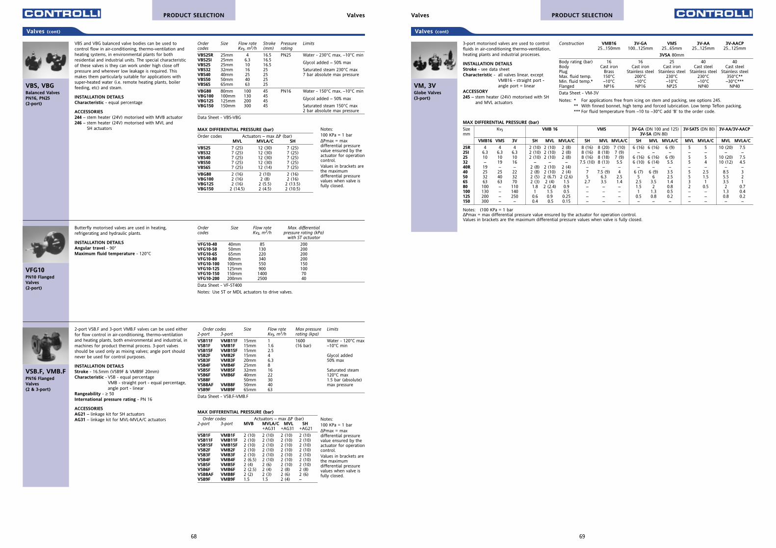
69
Valves (cont)
Construction VMB16 3V-GA VMS 3V-AA 3V-AACP25...150mm 100...125mm 25...65mm 25...125mm 25...125mm
3VSA 80mm
Body rating (bar) 16 16 25 40 40Body Cast iron Cast iron Cast iron Cast steel Cast steelPlug Brass Stainless steel Stainless steel Stainless steel Stainless steelMax. fluid temp. 150°C 200°C 230°C 230°C 350°C**Min. fluid temp.* –10°C –10°C –10°C –10°C –30°C***Flanged NP16 NP16 NP25 NP40 NP40
Data Sheet - VM-3V
Notes: * For applications free from icing on stem and packing, see options 245.** With finned bonnet, high temp and forced lubrication. Low temp Teflon packing.*** For fluid temperature from –10 to –30°C add ‘B’ to the order code.
3-port motorised valves are used to controlfluids in air-conditioning thermo-ventilation,heating plants and industrial processes.
INSTALLATION DETAILSStroke - see data sheetCharacteristic - all valves linear, except
VMB16 - straight port - angle port = linear
ACCESSORY245 – stem heater (24V) motorised with SH
and MVL actuators
VM, 3VGlobe Valves(3-port)
MAX DIFFERENTIAL PRESSURE (bar)
Size Kvs VMB 16 VMS 3V-GA (DN 100 and 125) 3V-SATS (DN 80) 3V-AA/3V-AACPmm 3V-SA (DN 80)
VMB16 VMS 3V SH MVL MVLA/C SH MVL MVLA/C SH MVL MVLA/C MVL MVLA/C MVL MVLA/C
25R 4 4 4 2 (10) 2 (10) 2 (8) 8 (16) 8 (20) 7 (10) 6 (16) 6 (16) 6 (9) 5 5 10 (20) 7.525I 6.3 6.3 6.3 2 (10) 2 (10) 2 (8) 8 (16) 8 (18) 7 (9) – – – – – – –25 10 10 10 2 (10) 2 (10) 2 (8) 8 (16) 8 (18) 7 (9) 6 (16) 6 (16) 6 (9) 5 5 10 (20) 7.532 – 19 16 – – – 7.5 (10) 8 (13) 5.5 6 (10) 6 (14) 5.5 5 4 10 (12) 4.540R 19 – – 2 (8) 2 (10) 2 (4) – – – – – – – – – –40 25 25 22 2 (8) 2 (10) 2 (4) 7 7.5 (9) 4 6 (7) 6 (9) 3.5 5 2.5 8.5 350 32 40 32 2 (5) 2 (6.7) 2 (2.6) 5 6.3 2.5 5 6 2.5 5 1.5 5.5 265 63 63 70 2 (3) 2 (4) 1.5 2.7 3.5 1.4 2.5 3.5 1.4 3 1 3.5 180 100 – 110 1.8 2 (2.4) 0.9 – – – 1.5 2 0.8 2 0.5 2 0.7100 130 – 140 1 1.5 0.5 – – – 1 1.3 0.5 – – 1.3 0.4125 200 – 250 0.6 0.9 0.25 – – – 0.5 0.8 0.2 – – 0.8 0.2150 300 – – 0.4 0.5 0.15 – – – – – – – – – –
Notes: (100 KPa = 1 bar ∆Pmax = max differential pressure value ensured by the actuator for operation control.Values in brackets are the maximum differential pressure values when valve is fully closed.
PRODUCT SELECTIONValves
68
Valves (cont)
Order Size Flow rate Stroke Pressure Limitscodes Kvs, m3/h (mm) rating
VBS25R 25mm 4 16.5 PN25 Water - 230°C max, –10°C minVBS25I 25mm 6.3 16.5
Glycol added – 50% maxVBS25 25mm 10 16.5VBS32 32mm 16 25 Saturated steam 230°C maxVBS40 40mm 25 25 7 bar absolute max pressureVBS50 50mm 40 25VBS65 65mm 63 25
VBG80 80mm 100 45 PN16 Water - 150°C max, –10°C minVBG100 100mm 130 45
Glycol added – 50% maxVBG125 125mm 200 45VBG150 150mm 300 45 Saturated steam 150°C max
2 bar absolute max pressure
Data Sheet - VBS-VBG
VBS and VBG balanced valve bodies can be used tocontrol flow in air-conditioning, thermo-ventilation andheating systems, in environmental plants for bothresidential and industrial units. The special characteristicof these valves is they can work under high close offpressure and wherever low leakage is required. Thismakes them particularly suitable for applications withsuper-heated water (i.e. remote heating plants, boilerfeeding, etc) and steam.
INSTALLATION DETAILSCharacteristic - equal percentage
ACCESSORIES244 – stem heater (24V) motorised with MVB actuator246 – stem heater (24V) motorised with MVL and
SH actuators
VBS, VBGBalanced ValvesPN16, PN25(2-port)
MAX DIFFERENTIAL PRESSURE (bar)
Order codes Actuators – max ∆P (bar)MVL MVLA/C SH
VBS25 7 (25) 12 (30) 7 (25)VBS32 7 (25) 12 (30) 7 (25)VBS40 7 (25) 12 (30) 7 (25)VBS50 7 (25) 12 (30) 7 (25)VBS65 7 (25) 12 (14) 7 (25)
VBG80 2 (16) 2 (10) 2 (16) VBG100 2 (16) 2 (8) 2 (16) VBG125 2 (16) 2 (5.5) 2 (13.5) VBG150 2 (14.5) 2 (4.5) 2 (10.5)
Notes:100 KPa = 1 bar ∆Pmax = maxdifferential pressurevalue ensured by theactuator for operationcontrol.Values in brackets arethe maximumdifferential pressurevalues when valve isfully closed.
Order codes Size Flow rate Max pressure Limits2-port 3-port Kvs, m3/h rating (kpa)
VSB11F VMB11F 15mm 1 1600 Water - 120°C maxVSB1F VMB1F 15mm 1.6 (16 bar) –10°C minVSB15F VMB15F 15mm 2.5 VSB2F VMB2F 15mm 4 Glycol addedVSB3F VMB3F 20mm 6.3 50% maxVSB4F VMB4F 25mm 8VSB5F VMB5F 32mm 16 Saturated steamVSB6F VMB6F 40mm 22 120°C maxVSB8F 50mm 30 1.5 bar (absolute)VSB8AF VMB8F 50mm 40 max pressureVSB9F VMB9F 65mm 63
Data Sheet - VSB.F-VMB.F
2-port VSB.F and 3-port VMB.F valves can be used eitherfor flow control in air-conditioning, thermo-ventilationand heating plants, both environmental and industrial, inmachines for product thermal process. 3-port valvesshould be used only as mixing valves; angle port shouldnever be used for control purposes.
INSTALLATION DETAILSStroke - 16.5mm (VSB9F & VMB9F 20mm)Characteristic - VSB - equal percentage
VMB - straight port - equal percentage, angle port - linear
Rangeability - ≥ 50International pressure rating - PN 16
ACCESSORIESAG21 – linkage kit for SH actuators AG31 – linkage kit for MVL-MVLA/C actuators
VSB.F, VMB.FPN16 FlangedValves(2 & 3-port)
MAX DIFFERENTIAL PRESSURE (bar)
Order codes Actuators – max ∆P (bar) 2-port 3-port MVB MVLA/C MVL SH
+AG31 +AG31 +AG21
VSB1F VMB1F 2 (10) 2 (10) 2 (10) 2 (10)VSB11F VMB11F 2 (10) 2 (10) 2 (10) 2 (10)VSB15F VMB15F 2 (10) 2 (10) 2 (10) 2 (10)VSB2F VMB2F 2 (10) 2 (10) 2 (10) 2 (10)VSB3F VMB3F 2 (10) 2 (10) 2 (10) 2 (10)VSB4F VMB4F 2 (6.5) 2 (10) 2 (10) 2 (10)VSB5F VMB5F 2 (4) 2 (6) 2 (10) 2 (10)VSB6F VMB6F 2 (2.5) 2 (4) 2 (8) 2 (8)VSB8AF VMB8F 2 (2) 2 (3) 2 (6) 2 (6)VSB9F VMB9F 1.5 1.5 2 (4) –
Notes: 100 KPa = 1 bar ∆Pmax = maxdifferential pressurevalue ensured by theactuator for operationcontrol.Values in brackets arethe maximumdifferential pressurevalues when valve isfully closed.
Order Size Flow rate Max. differentialcodes Kvs, m3/h pressure rating (kPa)
with ST actuator
VFG10-40 40mm 85 200VFG10-50 50mm 130 200VFG10-65 65mm 220 200VFG10-80 80mm 340 200VFG10-100 100mm 550 150VFG10-125 125mm 900 100VFG10-150 150mm 1400 70VFG10-200 200mm 2500 40
Data Sheet - VF-ST400
Notes: Use ST or MDL actuators to drive valves.
Butterfly motorised valves are used in heating,refrigerating and hydraulic plants.
INSTALLATION DETAILSAngular travel - 90°Maximum fluid temperature - 120°C
VFG10PN10 FlangedValves(2-port)
PRODUCT SELECTION Valves

71
Mod. Input Stroke/Time(s) Supply Input Control16.5 25 45 Signal
Raise Lower ActuatorsMVL26 22 33 60 230 V floatingMVL46 22 33 60 24 V floatingMVL46A 22 (16) 33 (25) 60 (45) 24 V floatingMVL46C 22 (16) 33 (25) 60 (45) 24 V floating
Proportional ActuatorsMVL56 22 33 60 24 V prop. (V or mA)MVL56A 22 (16) 33 (25) 60 (45) 24 V prop. (V or mA)MVL56C 22 (16) 33 (25) 60 (45) 24 V prop. (V or mA)
Data Sheet - MVL
Remark: MVL A/C models are fitted with spring return device.Values in brackets indicate the spring return time.A – spring return retracts (valve stem up)C – spring return extends (valve stem down)
ACCESSORIESDMVL – two auxiliary microswitches (SPDT) adjustable, rated 230V, 10 (3) amp.MVLPA2 – potentiometer for MVL2 (pcb with 1KΩ auxiliary pot.)MVLPA4 – potentiometer for MVL4 ”MVLPA4M – potentiometer for MVL46A and MVL46C ”245 – stem heater 24V (for valve applications with fluids below –10°C)AG31 – linkage kit for fitting actuator to VMB and VSG valves
MVL actuators have linear characteristic (linear ratiobetween input signal and valve coupling joint movement).They are used for fluid control in air-conditioning-heatingsystems and in industrial processes.
Two different control types are available:- floating (3-point)- proportional (dc voltage or current)
They are designed for direct coupling on all Controlliglobe valves (add AG31 linkage for V.B valves) and theymay also be used easily on valves of other manufacturerswith 0...45 mm stroke for floating action models or10...45 mm stroke for proportional action models.
INSTALLATION DETAILSStroke - MVL2/4 0...45 mm, MVL5 10...45 mmRunning speed - 1.33 s/mmThrust - MVL 1500 N, MVL.A/C 700 NProtection class - IP 55
MVLPulsed andProportional LinearValve Actuators(700N & 1500N)
Actuators (cont)
Model Supply Control signal
ST404 24Vac 2 positions, 3 points from controller ST405 230Vac ”
Data Sheet - VF-ST400
ST actuators are used to control VFG butterfly valves inheating, refrigeration and hydraulic plants.
INSTALLATION DETAILSAngular travel - 90°Timing - 360 secsTorque - 10 NmRadial force - 100 N (max)Protection class - IP 20Shaft - Ø 20mm with 18x6 key
STRotary ValveActuators(100N)
Model Stroke time (s) Torque Power Control 90°C 160°C (Nm) supply signal
MDL22 15 27 6 (8) 230Vac 3-pointMDL24 45 80 20 (27) ” ”MDL26 60 107 30 (40) ” ”
MDL42 15 27 6 (8) 24Vac 3-pointMDL44 45 80 20 (27) ” ”MDL46 60 107 30 (40) ” ”
MDL52 15 27 6 (8) 24Vac proportionalMDL54 45 80 20 (27) ” ”MDL56 60 107 30 (40) ” ”
Data Sheet - MDL
INSTALLATION DETAILSAction - direct/reversingAngular travel - 90° preset, 0...160° adjustable (55...160° adjustable - MDL5-)Thrust - 500 N maxProtection class - IP 55
ACCESSORYAF22 – coupling for VFG butterfly valves.
The MDL actuators are used in civil and industrial systemsfor driving dampers and other devices that require thecontrol of an angular position within a maximum angle of160° (e.g. for adjusting the flame n liquid or gas burners).
MDLDamper Actuators
PRODUCT SELECTIONActuators
70
Actuators
Model Control Control signal
MVT44 3 position 24Vac
Data Sheet - MVT
INSTALLATION DETAILSAction - direct/reversingStroke - 6.5mmRunning speed - 30 s/mm at 50 Hz, 25 s/mm at 60 HzThrust - 200 NProtection class - IP 40
MVT4 actuator is designed to provide, with VST and VSBTvalve bodies, floating control of hot/cool water intwo/four-pipe fan-coil units, zone and solar plants, reheatcoils and dehumidification batteries.
MVT44Fan-coli PulsedValve Actuator
Model Supply Control signal
MVT56 24Vac Proportional – ranges 0...10, 6...10, 0...4,2...10, 4...7, 6...9, 8...11Vac
Data Sheet - MVT5
INSTALLATION DETAILSAction - direct/reversingStroke - 6.5mmRunning speed - 30 s/mm at 50 Hz, 25 s/mm at 60 HzThrust - 200 NProtection class - IP 40
The MVT5 actuator is designed to provide proportionalcontrol of both VST and VSBT valve bodies in fan-coilunits, solar plants, reheaters and recoolers using hotand/or cold water.
MVT56Fan-coilProportional ValveActuator
Model Control Control signal (power supply)
MVA21 On/off (with cable) 110...230Vac MVA23 On/off ”
MVA41 On/off PWM (with cable) 24Vac MVA43 On/off PWM ”
Data Sheet - MVA2./4
INSTALLATION DETAILSAction - directStroke - 3.5mm (max)Stroke time - 3 min (opening), 8 min (closing)Thrust - 100 N (min)Protection class - IP 31
MVA actuators are used in V-ZB globe valve coupling forcool/warm water control in two and four pipe terminalunits and zone systems.
MVAElectro-thermalTerminal Unit andZone ValveActuators
Model Timing (secs) Supply Control signal
MVB26 65 230Vac FloatingMVB46 65 24Vac ”MVB56 65 24Vac Proportional (V– or mA)MVB52 30 24Vac ”
Data Sheet - MVB
Note: Timings refer to 16.5mm standard stroke. For different strokes see data sheet.
INSTALLATION DETAILSAction - direct/reversingStroke - 21mm max (mechanical end stroke)Thrust - 450 NProtection class - IP 50Output signal - for remote position indication 0...10V, 10...0V
ACCESSORIESD36 – two auxiliary microswitches (SPDT) adjustable, rated 230VMVBPA2 – potentiometer for MVB46 (pcb with 1KΩ auxiliary pot.)244 – stem heater 24V (for valve applications with fluids below –10°C)
These actuators are equipped with a reversingsynchronous motor and an electronic board available inthree different models respectively for:- floating control- proportional control (d.c. voltage or current)
Due to their versatility these actuators can be mountedboth on new ‘Controlli’ globe valves up to DN 2” as wellas on different manufacturers valves, with stroke from10.8 to 20mm.
Body valve Nominal diameter Model
PN16 DN 1/2”...2” VSB (2-port)PN16 DN 1/2”...2” VMB (3-port)
MVBPulsed andProportional LinearValve Actuators(450N)
Model Supply Control signal
SH222 24Vac 2 positions, 3 points from controller SH242 230Vac ”SH522 24Vac voltage or current variation from controller
Data Sheet - SH--2
ACCESSORIESAG21 – linkage kit for fitting actuator to VMB and VSB valves D5 – one auxiliary microswitch (SPST) at end of stroke, rated 230VP-140-1 – auxiliary potentiometer 140ΩP-1000-1 – auxiliary potentiometer 1000Ω245 – stem heater 24V (for valve applications with fluids below –10°C)
Series SH actuators are used in air conditioning,thermoventilation, heating systems and in industrialprocesses to drive dampers.
INSTALLATION DETAILSAngular travel - 160°Timing - 80 secsTorque - 12 NmRadial force - 1200 N (max)Protection class - IP 40Shaft - Ø 16mm with pin hole Ø 4mmManual overrideSH
Pulsed andProportional LinearValve Actuators(1200N)
PRODUCT SELECTION Actuators
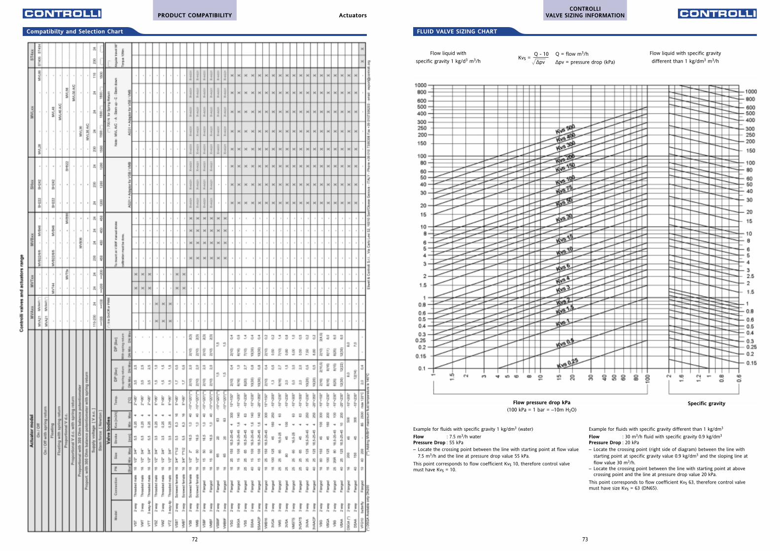
73
FLUID VALVE SIZING CHART
CONTROLLIVALVE SIZING INFORMATION
72
Compatibilty and Selection Chart
PRODUCT COMPATIBILITY Actuators
Example for fluids with specific gravity 1 kg/dm3 (water)
Flow : 7.5 m3/h waterPressure Drop : 55 kPa– Locate the crossing point between the line with starting point at flow value
7.5 m3/h and the line at pressure drop value 55 kPa.
This point corresponds to flow coefficient Kvs 10, therefore control valvemust have Kvs = 10.
Example for fluids with specific gravity different than 1 kg/dm3
Flow : 30 m3/h fluid with specific gravity 0.9 kg/dm3
Pressure Drop : 20 kPa– Locate the crossing point (right side of diagram) between the line with
starting point at specific gravity value 0.9 kg/dm3 and the sloping line atflow value 30 m3/h.
– Locate the crossing point between the line with starting point at abovecrossing point and the line at pressure drop value 20 kPa.
This point corresponds to flow coefficient Kvs 63, therefore control valvemust have size Kvs = 63 (DN65).
Flow pressure drop kPa(100 kPa = 1 bar = –10m H2O)
Specific gravity
Flow liquid with
specific gravity 1 kg/d3 m3/h
Flow liquid with specific gravity
different than 1 kg/dm3 m3/hKvs =
Q - 10 Q = flow m3/h
∆pv ∆pv = pressure drop (kPa)
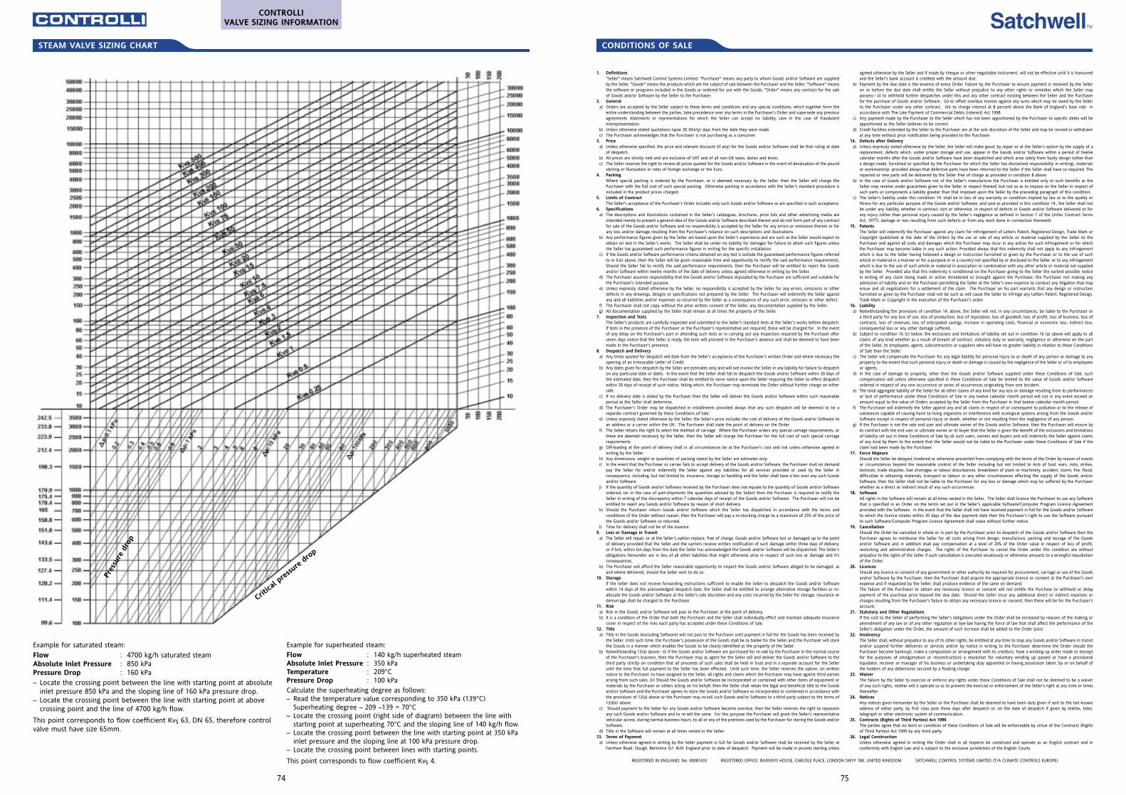
75
1. Definitions"Seller" means Satchwell Control Systems Limited. "Purchaser" means any party to whom Goods and/or Software are suppliedby the Seller. "Goods" means the products which are the subject of sale between the Purchaser and the Seller. "Software" meansthe software or programs included in the Goods or ordered for use with the Goods. "Order" means any contract for the saleof Goods and/or Software by the Seller to the Purchaser.
2. Generala) Orders are accepted by the Seller subject to these terms and conditions and any special conditions, which together form the
entire understanding between the parties, take precedence over any terms in the Purchaser's Order and supersede any previousagreements statements or representations for which the Seller can accept no liability, save in the case of fraudulentmisrepresentation.
b) Unless otherwise stated quotations lapse 30 (thirty) days from the date they were made.c) The Purchaser acknowledges that the Purchaser is not purchasing as a consumer.
3. Price a) Unless otherwise specified, the price and relevant discount (if any) for the Goods and/or Software shall be that ruling at date
of despatch. b) All prices are strictly nett and are exclusive of VAT and of all non-UK taxes, duties and levies. c) The Seller reserves the right to review all prices quoted for the Goods and/or Software in the event of devaluation of the pound
sterling or fluctuation in rates of foreign exchange or the Euro. 4. Packing
Where special packing is ordered by the Purchaser, or is deemed necessary by the Seller, then the Seller will charge thePurchaser with the full cost of such special packing. Otherwise packing in accordance with the Seller's standard procedure isincluded in the product prices charged.
5. Limits of ContractThe Seller's acceptance of the Purchaser's Order includes only such Goods and/or Software as are specified in such acceptance.
6. Specifications a) The descriptions and illustrations contained in the Seller's catalogues, brochures, price lists and other advertising media are
intended merely to present a general idea of the Goods and/or Software described therein and do not form part of any contractfor sale of the Goods and/or Software and no responsibility is accepted by the Seller for any errors or omissions therein or forany loss and/or damage resulting from the Purchaser's reliance on such descriptions and illustrations.
b) Any performance figures given by the Seller are based upon the Seller's experience and are such as the Seller would expect toobtain on test in the Seller's works. The Seller shall be under no liability for damages for failure to attain such figures unlessthe Seller has guaranteed such performance figures in writing for the specific installation.
c) If the Goods and/or Software performance criteria obtained on any test is outside the guaranteed performance figures referredto in 6.b) above, then the Seller will be given reasonable time and opportunity to rectify the said performance requirements.Should the Seller fail to rectify the said performance requirements, then the Purchaser will be entitled to reject the Goodsand/or Software within twelve months of the date of delivery unless agreed otherwise in writing by the Seller.
d) The Purchaser assumes responsibility that the Goods and/or Software stipulated by the Purchaser are sufficient and suitable forthe Purchaser's intended purpose.
e) Unless expressly stated otherwise by the Seller, no responsibility is accepted by the Seller for any errors, omissions or otherdefects in any drawings, designs or specifications not prepared by the Seller. The Purchaser will indemnify the Seller againstany and all liabilities and/or expenses so incurred by the Seller as a consequence of any such error, omission or other defect.
f) The Purchaser shall not copy, without the prior written consent of the Seller, any documentation supplied by the Seller. g) All documentation supplied by the Seller shall remain at all times the property of the Seller.
7. Inspection and TestsThe Seller's products are carefully inspected and submitted to the Seller's standard tests at the Seller's works before despatch.If tests in the presence of the Purchaser or the Purchaser's representative are required, these will be charged for. In the eventof any delay on the Purchaser's part in attending such tests or in carrying out any inspection required by the Purchaser afterseven days notice that the Seller is ready, the tests will proceed in the Purchaser's absence and shall be deemed to have beenmade in the Purchaser's presence.
8. Despatch and Delivery a) Any times quoted for despatch will date from the Seller's acceptance of the Purchaser's written Order and where necessary the
opening of an Irrevocable Letter of Credit. b) Any dates given for despatch by the Seller are estimates only and will not involve the Seller in any liability for failure to despatch
on any particular date or dates. In the event that the Seller shall fail to despatch the Goods and/or Software within 30 days ofthe estimated date, then the Purchaser shall be entitled to serve notice upon the Seller requiring the Seller to effect despatchwithin 30 days of receipt of such notice, failing which, the Purchaser may terminate the Order without further charge on eitherside.
c) If no delivery date is stated by the Purchaser then the Seller will deliver the Goods and/or Software within such reasonableperiod as the Seller shall determine.
d) The Purchaser's Order may be dispatched in installments provided always that any such despatch will be deemed to be aseparate contract governed by these Conditions of Sale.
e) Unless expressly stated otherwise by the Seller, the Seller's price includes the cost of delivery of the Goods and/or Software toan address or a carrier within the UK. The Purchaser shall state the point of delivery on the Order.
f) The Seller retains the right to select the method of carriage. Where the Purchaser orders any special carriage requirements, orthese are deemed necessary by the Seller, then the Seller will charge the Purchaser for the full cost of such special carriagerequirements.
g) Off-loading at the point of delivery shall in all circumstances be at the Purchaser's cost and risk unless otherwise agreed inwriting by the Seller.
h) Any dimensions, weight or quantities of packing stated by the Seller are estimates only. i) In the event that the Purchaser or carrier fails to accept delivery of the Goods and/or Software, the Purchaser shall on demand
pay the Seller for and/or indemnify the Seller against any liabilities for all services provided or used by the Seller inconsequence, including, but not limited to, insurance, storage or handling and the Seller shall have a lien over any such Goodsand/or Software.
j) If the quantity of Goods and/or Software received by the Purchaser does not equate to the quantity of Goods and/or Softwareordered, (or in the case of part-shipments the quantities advised by the Seller) then the Purchaser is required to notify theSeller in writing of the discrepancy within 7 calendar days of receipt of the Goods and/or Software. The Purchaser will not beentitled to reject any Goods and/or Software by reason of short delivery.
k) Should the Purchaser return Goods and/or Software which the Seller has dispatched in accordance with the terms andconditions of the Order without reason, then the Purchaser will pay a re-stocking charge to a maximum of 25% of the price ofthe Goods and/or Software so returned.
l) Time for delivery shall not be of the essence. 9. Loss or Damage in Transit
a) The Seller will repair, or at the Seller's option replace, free of charge, Goods and/or Software lost or damaged up to the pointof delivery provided that the Seller and the carriers receive written notification of such damage within three days of delivery,or if lost, within ten days from the date the Seller has acknowledged the Goods and/or Software will be dispatched. The Seller'sobligations hereunder are in lieu of all other liabilities that might otherwise arise in respect of such loss or damage and it'sconsequences.
b) The Purchaser will afford the Seller reasonable opportunity to inspect the Goods and/or Software alleged to be damaged, asand where delivered, should the Seller wish to do so.
10. StorageIf the Seller does not receive forwarding instructions sufficient to enable the Seller to despatch the Goods and/or Softwarewithin 14 days of the acknowledged despatch date, the Seller shall be entitled to arrange alternative storage facilities or re-allocate the Goods and/or Software at the Seller's sole discretion and any costs incurred by the Seller for storage, insurance ordemurrage shall be charged to the Purchaser.
11. Riska) Risk in the Goods and/or Software will pass to the Purchaser at the point of delivery. b) It is a condition of the Order that both the Purchaser and the Seller shall individually effect and maintain adequate insurance
cover in respect of the risks each party has accepted under these Conditions of Sale. 12. Title
a) Title in the Goods (excluding Software) will not pass to the Purchaser until payment in full for the Goods has been received bythe Seller. Until such time, the Purchaser's possession of the Goods shall be as bailee for the Seller and the Purchaser will storethe Goods in a manner which enables the Goods to be clearly identified as the property of the Seller.
b) Notwithstanding 12(a) above:- (i) if the Goods and/or Software are purchased for re-sale by the Purchaser in the normal courseof the Purchaser's business, then the Purchaser may as agent for the Seller sell and deliver the Goods and/or Software to thethird party strictly on condition that all proceeds of such sales shall be held in trust and in a separate account for the Selleruntil the time that full payment to the Seller has been effected. Until such time, the Seller reserves the option, on writtennotice to the Purchaser, to have assigned to the Seller, all rights and claims which the Purchaser may have against third partiesarising from such sales. (ii) Should the Goods and/or Software be incorporated or combined with other items of equipment ormaterials by the Purchaser or others acting on his behalf, then the Seller shall retain the legal and beneficial title to the Goodsand/or Software and the Purchaser agrees to store the Goods and/or Software so incorporated or combined in accordance withthe provisions of 12(a) above or the Purchaser may re-sell such Goods and/or Software to a third party subject to the terms of12(b)i) above.
c) Should payment to the Seller for any Goods and/or Software become overdue, then the Seller reserves the right to repossessany such Goods and/or Software and to re-sell the same. For this purpose the Purchaser will grant the Seller's representativevehicular access, during normal business hours, to all or any of the premises used by the Purchaser for storing the Goods and/orSoftware.
d) Title in the Software will remain at all times vested in the Seller. 13. Terms of Payment
a) Unless otherwise agreed in writing by the Seller payment in full for Goods and/or Software shall be received by the Seller atFarnham Road, Slough, Berkshire SL1 4UH, England prior to date of despatch. Payment will be made in pounds sterling unless
agreed otherwise by the Seller and if made by cheque or other negotiable instrument, will not be effective until it is honouredand the Seller's bank account is credited with the amount due.
b) Payment by the due date is the essence of every Order. Failure by the Purchaser to ensure payment is received by the Selleron or before the due date shall entitle the Seller without prejudice to any other rights or remedies which the Seller maypossess:- (i) to withhold further despatches under this and any other contract existing between the Seller and the Purchaserfor the purchase of Goods and/or Software. (ii) to offset overdue monies against any sums which may be owed by the Sellerto the Purchaser under any other contract. (iii) to charge interest at 8 percent above the Bank of England's base rate inaccordance with The Late Payment of Commercial Debts (interest) Act 1998.
c) Any payment made by the Purchaser to the Seller which has not been apportioned by the Purchaser to specific debts will beapportioned as the Seller believes to be correct.
d) Credit facilities extended by the Seller to the Purchaser are at the sole discretion of the Seller and may be revised or withdrawnat any time without prior notification being provided to the Purchaser.
14. Defects after Deliverya) Unless expressly stated otherwise by the Seller, the Seller will make good, by repair or at the Seller's option by the supply of a
replacement, defects which, under proper storage and use, appear in the Goods and/or Software within a period of twelvecalendar months after the Goods and/or Software have been dispatched and which arise solely from faulty design (other thana design made, furnished or specified by the Purchaser for which the Seller has disclaimed responsibility in writing), materialsor workmanship: provided always that defective parts have been returned to the Seller if the Seller shall have so required. Therepaired or new parts will be delivered by the Seller free of charge as provided in condition 8 above.
b) In the case of Goods and/or Software not of the Seller's manufacture the Purchaser is entitled only to such benefits as theSeller may receive under guarantees given to the Seller in respect thereof, but not so as to impose on the Seller in respect ofsuch parts or components a liability greater than that imposed upon the Seller by the preceding paragraph of this condition.
c) The Seller's liability under this condition 14. shall be in lieu of any warranty or condition implied by law as to the quality orfitness for any particular purpose of the Goods and/or Software, and save as provided in this condition 14., the Seller shall notbe under any liability, whether in contract, tort or otherwise, in respect of defects in Goods and/or Software delivered or forany injury (other than personal injury caused by the Seller's negligence as defined in Section 1 of the Unfair Contract TermsAct, 1977), damage or loss resulting from such defects or from any work done in connection therewith.
15. PatentsThe Seller will indemnify the Purchaser against any claim for infringement of Letters Patent, Registered Design, Trade Mark orCopyright (published at the date of the Order) by the use or sale of any article or material supplied by the Seller to thePurchaser and against all costs and damages which the Purchaser may incur in any action for such infringement or for whichthe Purchaser may become liable in any such action. Provided always that this indemnity shall not apply to any infringementwhich is due to the Seller having followed a design or instruction furnished or given by the Purchaser or to the use of sucharticle or material in a manner or for a purpose or in a country not specified by or disclosed to the Seller, or to any infringementwhich is due to the use of such article or material in association or combination with any other article or material not suppliedby the Seller. Provided also that this indemnity is conditional on the Purchaser giving to the Seller the earliest possible noticein writing of any claim being made or action threatened or brought against the Purchaser, the Purchaser not making anyadmission of liability and on the Purchaser permitting the Seller at the Seller's own expense to conduct any litigation that mayensue and all negotiations for a settlement of the claim. The Purchaser on his part warrants that any design or instructionfurnished or given by the Purchaser shall not be such as will cause the Seller to infringe any Letters Patent, Registered Design,Trade Mark or Copyright in the execution of the Purchaser's order.
16. Liabilitya) Notwithstanding the provisions of condition 14. above, the Seller will not, in any circumstances, be liable to the Purchaser or
a third party for any loss of use, loss of production, loss of reputation, loss of goodwill, loss of profit, loss of business, loss ofcontracts, loss of revenues, loss of anticipated savings, increase in operating costs, financial or economic loss, indirect loss,consequential loss or any other damage suffered.
b) Subject to condition 16 (c) below, the exclusions and limitations of liability set out in condition 16 (a) above will apply to allclaims of any kind whether as a result of breach of contract, statutory duty or warranty, negligence or otherwise on the partof the Seller, its employees, agents, subcontractors or suppliers who will have no greater liability in relation to these Conditionsof Sale than the Seller.
c) The Seller will compensate the Purchaser for any legal liability for personal injury to or death of any person or damage to anyproperty to the extent that such personal injury or death or damage is caused by the negligence of the Seller or of its employeesor agents.
d) In the case of damage to property, other than the Goods and/or Software supplied under these Conditions of Sale, suchcompensation will unless otherwise specified in these Conditions of Sale be limited to the value of Goods and/or Softwareordered in respect of any one occurrence or series of occurrences originating from one incident.
e) The total aggregate liability of the Seller for all other claims of any kind for any loss or damage resulting from its performancesor lack of performance under these Conditions of Sale in any twelve calendar month period will not in any event exceed anamount equal to the value of Orders accepted by the Seller from the Purchaser in that twelve calendar month period.
f) The Purchaser will indemnify the Seller against any and all claims in respect of or consequent to pollution or to the release ofsubstances capable of causing harm to living organisms or interference with ecological systems arising from the Goods and/orSoftware except in respect of personal injury or death, whether or not resulting from the negligence of any person.
g) If the Purchaser is not the sole end user and ultimate owner of the Goods and/or Software, then the Purchaser will ensure byits contract with the end user or ultimate owner or its buyer that the Seller is given the benefit of the exclusions and limitationsof liability set out in these Conditions of Sale by all such users, owners and buyers and will indemnify the Seller against claimsof any kind by them to the extent that the Seller would not be liable to the Purchaser under these Conditions of Sale if theclaim had been made by the Purchaser.
17. Force MajeureShould the Seller be delayed, hindered or otherwise prevented from complying with the terms of the Order by reason of eventsor circumstances beyond the reasonable control of the Seller including but not limited to Acts of God, wars, riots, strikes,lockouts, trade disputes, fuel shortages or labour disturbances, breakdown of plant or machinery, accident, storm, fire, flood,difficulties in obtaining materials, transport or labour or any other circumstances affecting the supply of the Goods and/orSoftware, then the Seller shall not be liable to the Purchaser for any loss or damage which may be suffered by the Purchaserwhether as a direct or indirect result of any such occurrences.
18. SoftwareAll rights in the Software will remain at all times vested in the Seller. The Seller shall licence the Purchaser to use any Softwarethat is specified in an Order on the terms set out in the Seller's applicable Software/Computer Program Licence Agreementprovided with the Software. In the event that the Seller shall not have received payment in full for the Goods and/or Softwareto which the licence relates within 30 days of the due payment date then the Purchaser's right to use the Software pursuantto such Software/Computer Program Licence Agreement shall cease without further notice.
19. CancellationShould the Order be cancelled in whole or in part by the Purchaser prior to despatch of the Goods and/or Software then thePurchaser agrees to reimburse the Seller for all costs arising from design, manufacture, packing and storage of the Goodsand/or Software and in addition shall pay compensation at a level of 20% of the Order value in respect of loss of profit,restocking and administrative charges. The rights of the Purchaser to cancel the Order under this condition are withoutprejudice to the rights of the Seller if such cancellation is executed vexatiously or otherwise amounts to a wrongful repudiationof the Order.
20. LicencesShould any licence or consent of any government or other authority be required for procurement, carriage or use of the Goodsand/or Software by the Purchaser, then the Purchaser shall acquire the appropriate licence or consent at the Purchaser's ownexpense and if requested by the Seller, shall produce evidence of the same on demand. The failure of the Purchaser to obtain any necessary licence or consent will not entitle the Purchase to withhold or delaypayment of the purchase price beyond the due date. Should the Seller incur any additional direct or indirect expenses orcharges resulting from the Purchaser's failure to obtain any necessary licence or consent, then these will be for the Purchaser'saccount.
21. Statutory and Other RegulationsIf the cost to the Seller of performing the Seller's obligations under the Order shall be increased by reasons of the making oramendment of any law or of any other regulation or bye-law having the force of law that shall affect the performance of theSeller's obligation under the Order, the amount of such increase shall be added to the Order price.
22. InsolvencyThe Seller shall, without prejudice to any of its other rights, be entitled at any time to stop any Goods and/or Software in transitand/or suspend further deliveries or services and/or by notice in writing to the Purchaser determine the Order should thePurchaser become bankrupt, make a composition or arrangement with its creditors, have a winding up order made or (exceptfor the purposes of amalgamation or reconstruction) a resolution for voluntary winding up passed or have a provisionalliquidator, receiver or manager of his business or undertaking duly appointed or having possession taken, by or on behalf ofthe holders of any debentures secured by a floating charge.
23. WaiverThe failure by the Seller to exercise or enforce any rights under these Conditions of Sale shall not be deemed to be a waiverof any such rights, neither will it operate so as to prevent the exercise or enforcement of the Seller's right at any time or timesthereafter.
24. NoticesAny notices given hereunder by the Seller or the Purchaser shall be deemed to have been duly given if sent to the last knownaddress of either party, by first class post three days after despatch or, on the date of despatch if given by telefax, telex,telegraph or other electronic system of communication.
25. Contracts (Rights of Third Parties) Act 1999 The parties agree that no term or condition of these Conditions of Sale will be enforceable by virtue of the Contracts (Rightsof Third Parties) Act 1999 by any third party.
26. Legal ConstructionUnless otherwise agreed in writing the Order shall in all respects be construed and operate as an English contract and inconformity with English Law and is subject to the exclusive jurisdiction of the English Courts.
REGISTERED IN ENGLAND: No. 00081433 REGISTERED OFFICE: INVENSYS HOUSE, CARLISLE PLACE, LONDON SW1P 1BX, UNITED KINGDOM SATCHWELL CONTROL SYSTEMS LIMITED (T/A CLIMATE CONTROLS EUROPE)
CONDITIONS OF SALESTEAM VALVE SIZING CHART
Example for superheated steam:Flow : 140 kg/h superheated steamAbsolute Inlet Pressure : 350 kPaTemperature : 209°CPressure Drop : 100 kPaCalculate the superheating degree as follows:– Read the temperature value corresponding to 350 kPa (139°C)
Superheating degree – 209 –139 = 70°C– Locate the crossing point (right side of diagram) between the line with
starting point at superheating 70°C and the sloping line of 140 kg/h flow.– Locate the crossing point between the line with starting point at 350 kPa
inlet pressure and the sloping line at 100 kPa pressure drop.– Locate the crossing point between lines with starting points.
This point corresponds to flow coefficient Kvs 4.
Example for saturated steam:Flow : 4700 kg/h saturated steamAbsolute Inlet Pressure : 850 kPaPressure Drop : 160 kPa– Locate the crossing point between the line with starting point at absolute
inlet pressure 850 kPa and the sloping line of 160 kPa pressure drop.– Locate the crossing point between the line with starting point at above
crossing point and the line of 4700 kg/h flow.
This point corresponds to flow coefficient Kvs 63, DN 65, therefore controlvalve must have size 65mm.
74
Pres
sure
dro
p
Critica
l pre
ssure
dro
p
CONTROLLIVALVE SIZING INFORMATION


