
P ro d u c tl ine s
B e n d i n g r o u n d i n g c u t t i n g
Many years’ specialisation
in sheet metal processing
and mechanical
engineering
Kurt Jorns founded
Jorns AG in 1973. Today
Jorns AG employs some
65 people and can look
back on a very successful
company history.
Thanks to many years’
specialisation in sheet
metal processing and
mechanical engineering,
Jorns AG is today
a global leader in the
development, sale and
production of bending
machines.
The family-run business
is in its second generation
under the management
of Business Administration
graduate Marc Jorns.
In cooperation with our
independent agencies, we
sell our products around
the world.
Our success is founded on
our strong focus on quality
and innovative power.
We are oriented to the
needs of our customers.
We integrate customer
requests into the develop-
ment of our products.
Tinsmiths, roofers and
building constructors
around the world rely on
the quality and cost-effec-
tiveness of our bending
machines, gutter machines
and cutting systems.
“We accept
only those orders
that we know
we can carry out
to the full
satisfaction
of our
customers”
In 2001, Kurt Jorns and
our development team
introduced the first double
bending machines. Thanks
to continual development
of the TwinPro which is
available today, these
product lines eliminate
the time- and energy-
consuming process of
rotating and flipping the
parts being processed.
s w i s s q u a l i t y w i t h g l o B a l i m P a c t
3
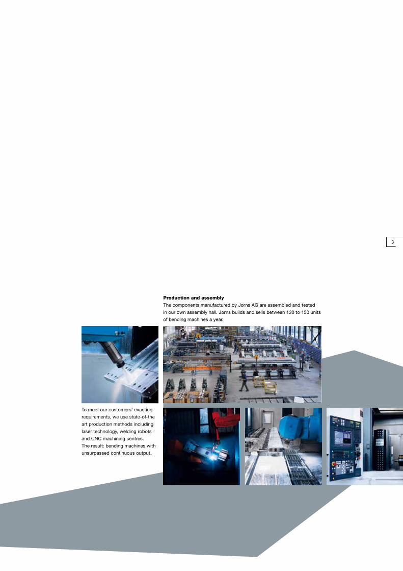
To meet our customers’ exacting
requirements, we use state-of-the
art production methods including
laser technology, welding robots
and CNC machining centres.
The result: bending machines with
unsurpassed continuous output.
Production and assembly
The components manufactured by Jorns AG are assembled and tested
in our own assembly hall. Jorns builds and sells between 120 to 150 units
of bending machines a year.
3

3.23.1 3.3
3
4/5
B e n d i n g
The Norma-Line, Maxi-
Line and Super-Line are
innovations of our existing
models. Our product
development is driven by
the ever-increasing
demands of our customers.
The modular design of the
bending machine enables
customers to configure
the machine to their
individual requirements.
3.1 SL shears / 3.2 SLE shears / 3.3 SL3 shears
All bending machines can be equipped with a SL/SLE shearing system for 1.5 mm steel sheets or a SL3
for 3 mm sheets.
With the SLE and SL3, the air gap and the overlap can be set for various steel sheet thicknesses.
Depending on the demands,
the system is equipped
with the following options:
graphically supported CNC
controls unit, depth stop,
conical depth stop, shearing
system, cutting systems,
hydraulic material thickness
adjustment, top beam
pretensioning or hem pre-
tensioning. The machines
are available in lengths
of 4, 6, 8, 10 and 12.2 m,
and the customer can
choose between the “S”
standard geometry or the
“The Jorns
product line
unites
experience,
technical know-
how, production
versatility
and future
prospects”
“F” geometry, which offers
more free space.
They can work steel sheets
up to a thickness of 3 mm
400 N/mm2.
Insertion depth is
1000 / 1250 mm.
3.53.4 5
2.42.3
6
26
1
5
4
2.21.1 1.2 3 2.1
275°
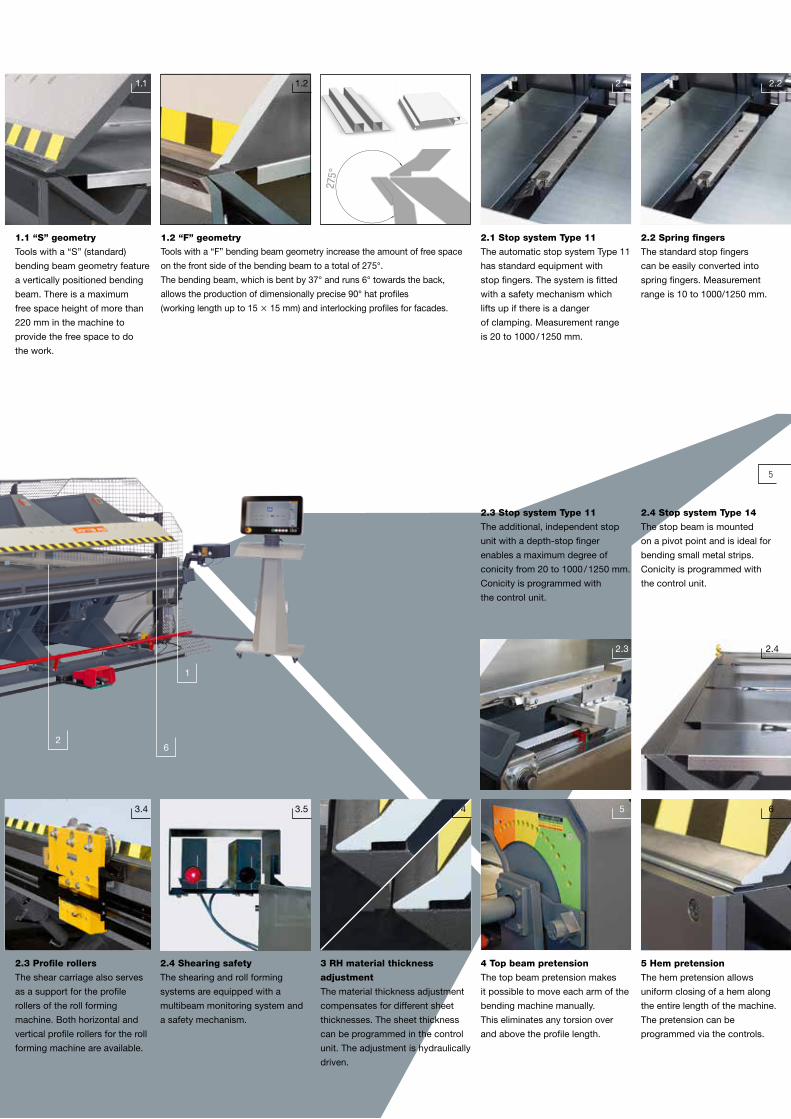
2.3 Stop system Type 11
The additional, independent stop
unit with a depth-stop finger
enables a maximum degree of
conicity from 20 to 1000 / 1250 mm.
Conicity is programmed with
the control unit.
2.4 Stop system Type 14
The stop beam is mounted
on a pivot point and is ideal for
bending small metal strips.
Conicity is programmed with
the control unit.
2.3 Profile rollers
The shear carriage also serves
as a support for the profile
rollers of the roll forming
machine. Both horizontal and
vertical profile rollers for the roll
forming machine are available.
2.4 Shearing safety
The shearing and roll forming
systems are equipped with a
multibeam monitoring system and
a safety mechanism.
3 RH material thickness
adjustment
The material thickness adjustment
compensates for different sheet
thicknesses. The sheet thickness
can be programmed in the control
unit. The adjustment is hydraulically
driven.
4 Top beam pretension
The top beam pretension makes
it possible to move each arm of the
bending machine manually.
This eliminates any torsion over
and above the profile length.
5 Hem pretension
The hem pretension allows
uniform closing of a hem along
the entire length of the machine.
The pretension can be
programmed via the controls.
2.1 Stop system Type 11
The automatic stop system Type 11
has standard equipment with
stop fingers. The system is fitted
with a safety mechanism which
lifts up if there is a danger
of clamping. Measurement range
is 20 to 1000 / 1250 mm.
2.2 Spring fingers
The standard stop fingers
can be easily converted into
spring fingers. Measurement
range is 10 to 1000/1250 mm.
1.1 “S” geometry
Tools with a “S” (standard)
bending beam geometry feature
a vertically positioned bending
beam. There is a maximum
free space height of more than
220 mm in the machine to
provide the free space to do
the work.
1.2 “F” geometry
Tools with a “F” bending beam geometry increase the amount of free space
on the front side of the bending beam to a total of 275°.
The bending beam, which is bent by 37° and runs 6° towards the back,
allows the production of dimensionally precise 90° hat profiles
(working length up to 15 15 mm) and interlocking profiles for facades.

P R O F I L B I E G E N7.1 7.2 8.28.1
7
8
10
B e n d i n g
Our bending machines
are mounted on a frame
and equipped with all
necessary levelling and
fastening devices.
They are driven by a
modern hydraulic unit.
Key terms such as propor-
tionally controlled speeds,
top beam with load relief,
hydraulic cylinder with
a ramp control and pipe-
break safety devices have
long been part of our
standard design vocabu-
lary.
“Tight tolerances
guarantee
that all individual
parts are easily
replaceable”
7.1 / 7.2 Coupling joint
The bending beam is bearing-mounted on coupling joints. The size
depends on the assembly. Elegant radii and scratch-free sheet surfaces
are the result of perfect lever ratios.
Stands and arms are de-
signed in sturdy, box-type
welded construction. Our
bending machines come
with user-friendly controls
mounted on a mobile con-
sole. To meet their specific
requirements, customers
can have their machines
equipped with a simple
OP3100 2-axis control unit,
a CP50 pure numeric unit
up through to the very
latest CP100 graphical
touchscreen control unit.
8.2 CP50 touchscreen con-
trol unit with a 5.7" TFT colour
display enables pure numeric
programming, without graphics
support.
8.1 OP 3100 2-axis
control unit
Simple controller with nine
angle-memory slots for systems
with or without a manual
depth stop system.
10.29 10.1
7
8.3 8.4
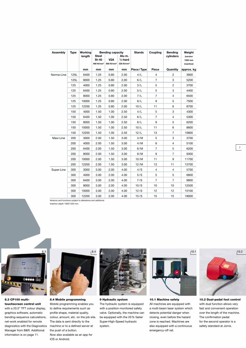
10.2 Dual-pedal foot control
with dual function allows very
fast and convenient operation
over the length of the machine.
The confirmation pedal
for the second operator is a
safety standard at Jorns.
8.4 Mobile programming
Mobile programming enables you
to define requirements such as
profile shape, material quality,
colour, amount, etc. on the job site.
The data is sent directly to the
machine or to a defined server at
the push of a button.
Now also available as an app for
iOS or Android.
8.3 CP100 multi-
touchscreen control unit
with a 20.5” TFT colour display,
graphics software, automatic
bending-sequence calculations,
net-work enabled for remote
diagnostics with the Diagnostics
Manager from B&R. Additional
information is on page 11.
Assembly Type Workinglength
Bending capacity Stands Coupling Bendingcylinders
Weight(version
1250 mm
insertion)
Steel St-40
400 N/mm2
V2A
600 N/mm2
Alu m. 1⁄2-hard220 N/mm2
mm mm mm mm Piece / Type Piece Quantity approx. kg
Norma-Line 125L 6400 1.25 0.80 2.00 4 / L 4 2 3800
125L 8000 1.25 0.80 2.00 6 / L 7 3 5200
125 4000 1.25 0.80 2.00 3 / L 5 2 3700
125 6400 1.25 0.80 2.00 5 / L 5 3 4400
125 8000 1.25 0.80 2.00 7 / L 7 4 6500
125 10000 1.25 0.80 2.00 8 / L 9 5 7500
125 12200 1.25 0.80 2.00 10 / L 11 6 8700
150 4000 1.50 1.00 2.50 4 / L 5 3 4300
150 6400 1.50 1.00 2.50 6 / L 7 4 5300
150 8000 1.50 1.00 2.50 8 / L 9 5 6200
150 10000 1.50 1.00 2.50 10 / L 11 6 8600
150 12200 1.50 1.00 2.50 12 / L 13 7 10800
Maxi-Line 200 3000 2.00 1.50 3.00 3 / M 5 3 3700
200 4000 2.00 1.50 3.00 4 / M 6 4 5100
200 6400 2.00 1.50 3.00 6 / M 7 5 6200
200 8000 2.00 1.50 3.00 8 / M 9 7 9300
200 10000 2.00 1.50 3.00 10 / M 11 9 11700
200 12200 2.00 1.50 3.00 12 / M 13 11 13700
Super-Line 300 3000 3.00 2.00 4.00 4 / S 4 4 5700
300 4000 3.00 2.00 4.00 5 / S 5 5 6800
300 6400 3.00 2.00 4.00 7 / S 7 7 9800
300 8000 3.00 2.00 4.00 10 / S 10 10 12500
300 10000 3.00 2.00 4.00 12 / S 12 12 15100
300 12200 3.00 2.00 4.00 15 / S 15 15 18000Versions and functions subject to alterations and additions!
Insertion depth 1000/1250 mm.
10.1 Machine safety
All machines are equipped with
a multi-beam laser system which
detects potential danger when
closing, even before the hazard
zone is reached. Machines are
also equipped with a continuous
emergency-off rail.
9 Hydraulic system
The hydraulic system is equipped
with a position-monitored safety
valve. Optionally, the machine can
be equipped with the 20 % faster
Super-High-Speed hydraulic
system.

1.1 1.2 1.3
T WI NM AT IC
“The TwinPro
guarantees
cost-effective,
flexible and safe
operation”
Double bending is the
cost-effective trend in
sheet metal processing.
The TwinPro operates using
an innovative, pioneering
bending technology capa-
ble of coping with the most
exacting requirements.
The modular design of the
TwinPro concept enables
customers to configure the
machine to their individual
requirements. Depending
on demands, the system
is automatically equipped
with a fully automatic
gripping system (pneu-
matic or hydraulic) or a
Type 11 stop system.
A large selection of options
allows the user to configure
the system as required.
1 Pneumatic clamping finger
Each unit includes a pneumatic combination clamping finger. Flat sheets can be automatically stopped
up to a minimum stop position of 15 mm (fully automatic) or 11 mm (semi-automatic). Folded sheets
with a shank height of up to 25 mm can be gripped. In addition to the short stop dimensions, the system
boasts a maximum stop length of 1200 / 1350 mm at a speed of 250 mm/s.
Special clamping fingers or other stop system available on request.
c o s t- e F F e c t i V e n e s s i n d o u B l e B e n d i n g
t w i n P r o

43 52.1 2.2
9
6.1 6.36.2 6.4 6.5
6.1/6.3 6.2/6.4
5
1/2/3
4
2 Hydraulic clamping finger
Every unit contains a hydraulic clamping finger and overgripping
clamping finger. Flat sheets can be automatically stopped up
to a minimum stop position of 25 mm (fully automatic) or 17 mm
(semi-automatic). Folded sheets with a shank height of up to 40 mm
can be gripped. The system boasts a maximum stop dimension
of 1150 / 1300 mm and travels at 250 mm/s.
3 Stop system Type 11
Using the stop system Type 11,
the double bending machine can
be used as a semi-automatic
system. The stop fingers can be
moved along the entire working
length. Travel path 25 to
1150 / 1300 mm (with spring finger,
10 to 1150 / 1300 mm).
4 Short-piece clamping finger
Makes it possible to right-angle
clamp short sheets that are 70 mm
(hydraulic) or 132 mm (pneumatic)
in length.
5 Conical stop
Independent of the selected
stop and clamping system,
the system can be equipped
with an additional stop to create
conical profiles either semi-
or fully automatically.
t w i n P r o 6.3 “G” geometry
Tools with a “G” bending beam geometry increase the amount of free
space on the front side of the bending beam to a total of 269°.
The bending beam, which is bent by 37°, allows the production
of dimensionally precise 90° hat profiles and interlocking profiles for
facades.
6.1 “S” geometry
Tools with a “S” (standard) bending beam geometry feature a vertically
positioned bending beam.
6.5 Free space
While one bending beam
is working, the other beam can
be moved out of the bending
area by up to 295 mm. There is
a maximum free space height
of more than 220 mm in the
machine to provide the free
space to do the work.

7.1
With positive-negative
bending using two bending
beams, the TwinPro is more
adaptable and many times
faster than conventional
bending machines. There
is no longer any need
for auxiliary personnel.
Unit costs are crucial,
especially in industrial
bending. High employment
costs often seriously
impact lucrative orders.
Long, heavy workpieces,
in particular, with many
reverse-bending operations
also entail considerable
added expense.
It is specifically in this area
of operation that the fully
automatic TwinMatic-Pro
and the semi-automatic
TwinBend-Pro come into
their own. Both machines
are available in lengths of
4, 6.4, 8, 10 and 12.2 m.
They can work steel sheets
up to a thickness of 3 mm
(400 N/mm2). The insertion
depth is 1200 / 1350 mm.
CP100Twin control unit
• With 21.5" multi-touchscreen
• Full HD (16:9) and 3.0-GHz
processor
• 9 CNC-controlled axes
(top beam, top and bottom
bending beam, top and bottom
bending beam displacement,
material-reinforcement adjust-
ment, stop, conical stop, shears)
• External programming software
• Remote maintenance with the
Diagnostics Manager from B&R.
• USB flash memory
• 1 GB main memory and 32 GB
solid-state drive
• State-of-the-art Ethernet
technology
• B&R hardware components
“The CP100Twin
control system
is simple
to program
and adds
considerably
to the overall
appeal of the
machines”
TwinMatic-Pro TwinBend-Pro
Type Workinglength
Bending capacity Stands / arm
Bendingcylinders
Weight Clamping fingers (recommended)
Stop fingerincl.
spring finger (recommended)
TwinPro Steel St-40
400 N/mm2
Inox V2A
600 N/mm2
Alu m. 1⁄2-hard220 N/mm2
mm mm mm mm Quantity Quantity kg Quantity Quantity
125 3200 1.25 0.80 1.50* 2 4 3700 2 4
125 6400 1.25 0.80 1.50* 4 8 6900 4 4
125 8000 1.25 0.80 1.50* 5 10 9250 5 4
125 10000 1.25 0.80 1.50* 6 12 11100 6 6
125 12200 1.25 0.80 1.50* 8 16 14800 8 6
150 4000 1.50 1.00 2.00* 3 6 5900 3 4
150 6400 1.50 1.00 2.00* 5 10 8400 4 4
150 8000 1.50 1.00 2.00* 7 14 10950 5 4
150 10000 1.50 1.00 2.00* 8 16 13500 8 6
150 12200 1.50 1.00 2.00* 10 20 18500 9 6
200 4000 2.00 1.50 3.00 4 8 8300 3 4
200 6400 2.00 1.50 3.00 6 12 10300 5 4
200 8000 2.00 1.50 3.00 8 16 12200 6 4
200 10000 2.00 1.50 3.00 9 18 15300 8 6
200 12200 2.00 1.50 3.00 12 24 18300 11 6
300 4310 3.00 2.00 4.00 4 8 13000 3 4
300 6410 3.00 2.00 4.00 6 12 18000 5 4
300 8510 3.00 2.00 4.00 8 16 24500 7 4
300 10610 3.00 2.00 4.00 10 20 30000 9 6
300 12710 3.00 2.00 4.00 12 24 36000 11 6
* Bending performance in aluminium can be increased by +0.5 mm through the use of the material thickness adjustment (optional).Versions and functions subject to alterations and additions!
7.1 Preparing drawings
Our drawing software lets you
create profiles very easily:
the workpiece is designed step
by step on the screen or on an
external PC. The software
automatically prompts you
forkey data-e.g. flange length,
bending angle, radius, stop,
sheet thickness, and sheet
quality.
c o s t- e F F e c t i V e n e s s i n d o u B l e B e n d i n g

7.2 7.3 7.4
11
7.5
9 1110
7
108
9
9 128
7.2 Automatic mode /
process simulation
After the profile has been
created, the defined
bending sequence is automati-
cally simulated using the
bending-sequence calcula-
tions. Possible collisions are
displayed.
7.3 Folder storage
The CP100Twin touch control
system is Windows-based, which
means you can store profiles
in a customised folder structure.
The program also allows you to
search for and open profiles using
predefined criteria.
7.4 Sketching mode
The sketching mode makes it
even easier to create profiles by
working directly on the touchscreen
control system.
7.5 Mobile programming
Mobile programming enables
you to define requirements
such as profile shape, material
quality, colour, amount, etc.
on site. The data are sent
directly to the machine or to a
defined server at the push
of a button.
Now also available as an app
for iOS or Android.
10 Material thickness
adjustment RH
The material thickness adjustment
compensates for different sheet
thicknesses. Sheet thickness can
be programmed with the controls.
The adjustment is hydraulically
driven. With aluminium, bending
performance increases by
+0.5 mm. Standard from Twin-
Pro-200/300.
9 Bending beam pretension
Bending beam pretension makes
it possible to individually adjust
each bending beam section in the
bending machine as needed. In
this way, twisting can be
eliminated over the total length
of the profile.
8 Hem pretension
The hem pretension allows
uniform closing of a hem along
the entire length of the
machine. The pretension can be
programmed via the controls.
11 SL, SLE and SL3 shears
All systems can be equipped with a
SL/SLE shearing system for 1.5 mm
steel sheets or a SL3 for 3 mm
sheets. The shear carriage also
serves as a support for the profile
rollers of the roll forming machine.
The systems are equipped with a
multi-beam monitoring system
and a safety mechanism.
12 Multiproportional
hydraulic system
The multiproportional hydraulic
system is equipped with multiple
proportional hydraulic valves
and makes it possible to move
multiple hydraulically driven axes
simultaneously. In this way, cycle
time is reduced by approximately
15 % over the entire profile.

T WI NM AT IC
1
“The cost-
effective solution
for
manufacturing
standard
and special
gutters”
The gutter machine from
Jorns AG is the optimal
solution for manufac-
turing gutters and curves
in a variety of shapes and
lengths. Depending on the
design, the system is able
to handle the processing
of materials up to 1.25 mm
thick (copper sheets) and a
length of up to 10 metres.
Possible integration into
a fully automatic manu-
facturing line was already
considered during its
development.
r o u n d i n g

4.13 4.21 2
13
2
3
4
4.1 Stop system Type RM
A simple stop system allows
the precise positioning of the raw
materials.
4.2 Stop system Type 11
The stop system Type 11 has
standard equipment with stop
fingers. The system is fitted
with a safety mechanism which
lifts up if there is a danger
of clamping.
3 Supporting table
All machines are equipped with
removable sheet cassettes.
2 Pretension
Roller pretension for each mounting
point allows the precise setting of
two underlying rollers against the
upper roller. The adjustment allows
a uniform rounding over the entire
length of the working surface.
1 Three rollers
Three synchronously driven
rollers with a diameter of
40 mm can produce narrow
curves following each other
closely.
g u t t e r m a c h i n e
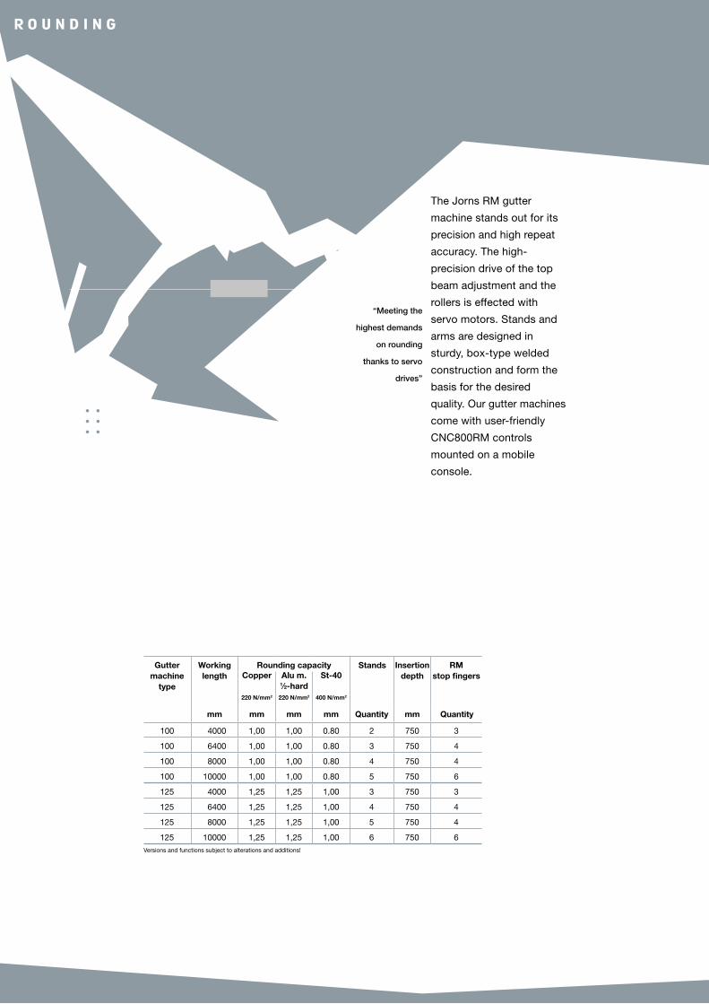
The Jorns RM gutter
machine stands out for its
precision and high repeat
accuracy. The high-
precision drive of the top
beam adjustment and the
rollers is effected with
servo motors. Stands and
arms are designed in
sturdy, box-type welded
construction and form the
basis for the desired
quality. Our gutter machines
come with user-friendly
CNC800RM controls
mounted on a mobile
console.
“Meeting the
highest demands
on rounding
thanks to servo
drives”
Guttermachine
type
Workinglength
Rounding capacity Stands Insertion depth
RM stop fingersCopper
220 N/mm2
Alu m. 1⁄2-hard 220 N/mm2
St-40
400 N/mm2
mm mm mm mm Quantity mm Quantity
100 4000 1,00 1,00 0.80 2 750 3
100 6400 1,00 1,00 0.80 3 750 4
100 8000 1,00 1,00 0.80 4 750 4
100 10000 1,00 1,00 0.80 5 750 6
125 4000 1,25 1,25 1,00 3 750 3
125 6400 1,25 1,25 1,00 4 750 4
125 8000 1,25 1,25 1,00 5 750 4
125 10000 1,25 1,25 1,00 6 750 6Versions and functions subject to alterations and additions!
r o u n d i n g

15
7.27.1 865
5 7
8
8 CNC800RM
Touchscreen control
15" colour TFT display,
network-enabled for remote
diagnosis, automatic rear stop
and graphics software.
7 Height-adjustable table
Upon request, the system is equipped with a pneumatic height-adjustable
table whereby sheets which have already been shaped below can be laid
down and rounded.
6 2-pedal foot controls
With dual functions, allows very
fast and simple operation over the
full length of the machine.
The confirmation pedal for the
second operator is a safety
standard at Jorns.
5 Roller safety
The roller system is equipped
with a multi-beam laser system
which detects potential danger
when closing, even before
the hazard zone is reached.
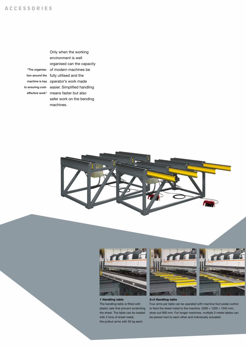
2 31
1 Handling table
The handling table is fitted with
plastic rails that prevent scratching
the sheet. The table can be loaded
with 2 tons of sheet metal,
the pullout arms with 50 kg each.
Only when the working
environment is well
organised can the capacity
of modern machines be
fully utilised and the
operator’s work made
easier. Simplified handling
means faster but also
safer work on the bending
machines.
“The organisa-
tion around the
machine is key
to ensuring cost-
effective work”
a c c e s s o r i e s
2+3 Handling table
Four arms per table can be operated with machine foot pedal control
to feed the sheet metal to the machine. 2000 × 1200 × 1045 mm,
draw-out 800 mm. For longer machines, multiple 2-metre tables can
be placed next to each other and individually actuated.

31 2
17
c u t t i n g
Z s t
2 Models
The 1000 mm and 1250 mm HTS
versions can be set up left or right.
3 Quality
High-quality materials and
precision-produced parts
ensure a long service life of the
Jorns HTS.
1 Operation
The shearing carriage is easily
pulled over the table with the
extension lever.
A hold-down device prevents the
sheet from slipping.
h t s
ZST cutting table
Sturdy underframe, phenol chip-
board, stop and lateral tape
measure. The table is mobile and
has wheel brakes. Available in
lengths of 4, 6, and 8 m and table
widths of 1000 and 1250 mm.
HTS manual table shears
Swivel bearings for rotating the
shears away from the table surface.
Available in widths of 1000 mm and
1250 mm. Cutting capacity:
1.0 mm St-40, 0.6 mm Inox steel,
1.5 mm aluminium.

3
3 4
Jorns slitting machines
are characterised by short
adjustment and retooling
times.
The machine can be used
for continuously changing
production units as well
as for series production.
The Mini Service Centre
(MSC) is the ideal,
most cost-effective and
professional solution
on the market.
The steadily growing
number of satisfied
customers confirms our
concept and represents
the reward for our
development work.
“Our global
customer service
with skilled
servicing
engineers
guarantees
professional
installation,
training and
maintenance of
the equipment”
u n c o i l i n g s P l i t t i n g c o i l i n g
1 Uncoiler
Frequency-controlled uncoiler for
the Mini Service Centre assembly.
Designed for strips of 1250 mm
and 1500 mm and a load-carrying
capacity of 5000 kg.
Ideal for steel sheet thicknesses
of up to 1.5 mm (400 N/mm2).
The sheet coil is tensioned by hand
using a crank. Two lateral plates
permit perfect unwinding
of the coil. The standard speed
of 35 m / min is regulated by a
dancer shaft.
Accessories:
A hydraulic loading block – univer-
sally useful for all sizes of coil
and a maximum load-carrying
capacity of 5000 kg – complements
our offer. The block and the
height adjustment are operated
hydraulically. Thanks to the
special design, the overall machine
height is low.
2 Slitting machine
The slitting machine of the Mini
Service Centre assembly is
available in strip widths of
1250 mm and 1500 mm for sheet
thicknesses of 1.25 mm and
1.5 mm steel sheet (400 N/mm2).
The slitting machine can be con-
figured either without straightening
unit or with 5 or 7 straightening
rollers. The machine runs in the
middle at a speed of 35 m / min,
ensuring that the cutting force is
ideally distributed. The slitting
blades can be mechanically
clamped and are quickly adjusted
by hand to the required strip
width (minimum slitting width is
70 mm).
Accessories:
Foil holder, additional slitting
blades.
3 Recoiler
The recoiler of the Mini Service
Centre assembly is available in strip
widths of 1250 mm and 1500 mm
and for maximum carrying-load
capacity of 5000 kg.
The strips are braked using a
pneumatic felt brake. A recoiler
tightly tensions the strips. The
separating discs guarantee that the
strips are aligned true when wound.
The minimum strip width that can
be wound is 75 mm.
4 Scrap coiler
Stepped arrangement with
central electric motor.
The finger moves constantly
back and forth to distribute
the rest of the strip evenly over
the mandrel. The maximum
strip width is 25 mm.
The winding speed of 35 m/min is generated by an electric drive
and controlled via a dancer shaft. The maximum steel sheet thickness
which can be wound with the Jorns recoiler is 1.0 mm for aluminium,
1.0 mm for steel sheets and 0.6 mm for stainless steel.
The best recoiling results are achieved with 3 to 4 strips.
Accessories:
A hydraulic loading block – universally useful for all sizes of coil and
a maximum load-carrying capacity of 5000 kg – complements our offer.
The block and the height adjustment are operated hydraulically.
Thanks to the special design, the overall machine height is low.

1
219
m s c
Max. processable sheet thickness
Size Slittingshaft
X
Slittingblades
X
Bladepairs
Strip width 1250 Strip width 1500 Straightening unitSteel St-40
400 N/mm2
Alu m. 1⁄2-hard220 N/mm2
Inox
600 N/mm2
Steel St-40
400 N/mm2
Alu m. 1⁄2-hard220 N/mm2
Inox
600 N/mm2
R55 Straightening
shafts
R77 Straightening
shafts
mm mm Quantity mm mm mm mm mm mm
MSC 125 100 152 5 1.25 1.75 0.75 • •
MSC 125 140 202 5 1.25 1.75 0.75 • •
MSC 150 140 202 5 1.50 2.00 1.00 1.50 2.00 1.00 • •Versions and functions subject to alterations and additions!
Throughput width greater than strip width.

JORNS AG
Kirchgasse 12
CH-4932 Lotzwil
Switzerland
Phone +41 (0)62 919 80 50
Fax +41 (0)62 919 80 69
www.jorns.ch
Represented by:
B e n d i n g r o u n d i n g c u t t i n g
E |
10.1
4
AlgeriaSarl SOUDETOLEDZ-ALGERIETel. +213 24 88 03 [email protected]
AustraliaAcra machinery P/LAU-MelbourneTel. +61 3 97 94 66 [email protected]
Austria (exkl. Vorarlberg)AustroDachHandelsgesmbH & Co KGAT-4300 St. ValentinTel. +43 7435 [email protected]
Belgium, Luxembourg, Northern France D.A.C. Machines NVBE-8800 RoeselareTel. +32 51 24 33 [email protected]
Bosnia, Croatia, Serbia, MacedoniaMAREX ZAGREB D.O.O.HR-53270 SenjTel. +385 1 6198 [email protected]
Czech RepublicFawi spol. s.r.o.CZ-147 00 Praha 4Tel. +42 02 41 431 [email protected]
FinlandNoritek OyFI-01510 VantaaTel. +358 10 386 83 [email protected]
FranceTyma DiffusionFR-71880 Chatenoy le Royal / Chalon sur SaoneTel. +33 385 450 [email protected]
GermanyMaschinen StockertGrosshandels GmbHDE-85662 HohenbrunnTel. +49 810 28 94 [email protected]
Great BritainI - Mach Ltd.GB-NN6 0NF NorthamptonTel. +44 160 48 10 [email protected]
GreeceReimport Repanis Ltd.GR-15122 AthenTel. +30 210 28 51 [email protected]
HungaryArli MO Kft. - Jorns Képviselet.H-1037 BudapestTel. +36 14 53 37 [email protected]
IndiaAPT Precision TechnologiesIN-Pune 411051Tel. +91 985 00 [email protected]
IndonesiaPT. Tecno Mesin Utama D -14240 Jakarta Utara Tel. +62 21 4586 5621 pt tmu@pt tmu.co.id www.pt tmu.co.id
Ireland Lister Machine Tools Ltd.IE-Dublin 12Tel. +353 1 450 88 [email protected]
IsraelG.M.T.Greenberg-Machine Tools Ltd.IL-Tel Aviv 65117Tel. +972 356 00 631/56 60 [email protected]
ItalyAlpewa GmbH/srl.IT-25017 Lonato del Garda (BS)Tel. +39 030 206 [email protected]
NetherlandsFlevo TradingNL-3899 BR ZeewoldeTel. [email protected]
New ZealandScott Machinery LimitedNZ-ChristchurchTel. +64 3 349 22 [email protected]
North America (USA), Canada, Mexico, CaribbeanMetalforming Inc.USA-Peachtree City, GA 30269Tel. +1 770 631 [email protected]
Northern Ireland Lister Machine Tools (NI) Ltd.NI-Belfast BT12 6HPTel. +44 28 9066 [email protected]
PolandPolteknik Ltd. Sp. z.o.o.PL-80-297 BaninoTel. +48 58 684 [email protected]
PortugalResiper Comércio de Máquinase Acessórios Industriais Lda.PT-3740-339 Sever de VougaTel. +351 234 555 [email protected]
RumaniaSC Euro Tehnics Srl RO- 555300 CisnadieTel. +40 269 235 511 [email protected] www.eurotehnics.ro
RussiaFOSTRU-107023, MoscowTel +7 [email protected]
Slovak RepublicMT-MONT s.r.oSK-82107, BratislavaTel. +421 911 [email protected]
SloveniaMarex d.o.o.SI-1290 GrosupljeTel. +386 1 788 83 [email protected]
SpainSUPRAFORM, S.L. ES -08850 Gavà BARCELONATel. +34 93 663 13 00 [email protected] www.supraform.net
Sweden Belano Maskin AGSE - 44118 AlingsasTel. +46 322 15 [email protected]
SwitzerlandAustria: Vorarlberg Gebr. Spiegel AGCH-8280 KreuzlingenTel. +41 71 677 60 [email protected]
TurkeyUltra MetalMümessillik San.ve Tic.A.S. TR -35110 IzmirTel. +90 533 372 95 49 [email protected] www.ultrametal.com.tr
UkraineD.A.C. UkraineUA-22400 KalynovkaTel. +32 51 24 33 [email protected]
![INDEX [] · 6 Application S.F. FOOD INDUSTRY Cereal Cooker 1.25 Dough Mixer 1.50 Meat Grinder 1.50 Slicers 1.50 GENERATORS AND EXITORS 1.25 HAMMER MILLS 2.00 …](https://cdn.vdocument.in/doc/165x107/5b3f84f17f8b9a3a138c3442/index-6-application-sf-food-industry-cereal-cooker-125-dough-mixer-150.jpg)
![3187-1615 Paviljoen Provil Lommen s… · materiaal factor 1.25 (houten balk) EI [Nmm2] 6.80E+11 0.80 V OLD ET kmod 0.8 (basis) GA [N] 7.49E+06 maatgevend;stijf heid uiterlijk Ksys](https://cdn.vdocument.in/doc/165x107/611e89fbdf43574e00543607/3187-1615-paviljoen-provil-s-materiaal-factor-125-houten-balk-ei-nmm2-680e11.jpg)


