NASA-CR-167993 19850003751
NlIsA - (!l~ -J~ 7;993
NJ\SJ\ NatIOnal Aeronautics and Space AdminIstratIOn
NASA CR-167993 R82AEB540
Volume II
Materials for Advanced Turbine Engines Project Completion Report
Project 2 Rene 150 Directionally Solidified
Superalloy Turbine Blades
Volume II
by G.J. DeBoer
General Electric Company Aircraft Engine Business Group
Aircraft Engine Engineering Division Cincinnati, Ohio 45215
Prepared for:
, :J r (..' ~o8f) \ ,- 1,1. ,)
L/\NGLEY RES[,c\,,~,~ '~ENT;::R L!G1ARY, NASA.
HA',:PTON, VIRGINIA
~~ATIONAL AERONAUTICS AND SPACE '"OMINISTI(~:nON LEWIS RESEARCH CENTER
21000 IROOK?ARK ROAD Cl.eVElAND, I,)HIO 441:J!
1/11111111111 1111 11/1111111111111111111111111 NF01864
https://ntrs.nasa.gov/search.jsp?R=19850003751 2018-09-01T07:04:21+00:00Z


1 Report No 2 Government Accession No 3 Recipient's Catalog No NASA CR-167993
4 Title .nd Subtitle 5 Report Oat. Rene 150 Dlrectl0nally Solldifled Superalloy Turblne Blades - February, 1982 Volume II 6 Performing Or~nlzatlon Code
7 Autl>or(s) 8 Performing Or~nlzatlon Report No
G.,]. DeBoer R82AEB540 Volume II
10 Work Unit No 9 Performing Or9l"IZltion Name IIId Address
General Electrlc Company 11 ContrlCt or Grant No Alrcraft Englne Business Group NAS3-20074 Cincinnatl, Ohl0 45215
13 Type of Report and Period Covered 12 Sponsoring AIJencY Name and Address Flnal (Project 2, Vol. II)
Natl0nal Aeronautlcs and Space Administration 14 Spon_,ng Agency Code Washington, D.C. 20456
15 Supplementary Notes -Project Manager: Coulson M. Scheuermann, Materials D1vislon •
NASA Lewis Research Center, Cleveland, Ohio
16 Abstract
ThlS report presents the results of the engine testing of Rene 150 Stage 1 Hlgh Pr~ssure Turblne blades ln CF6-50 core and fan engines. The core engine test was conducted for 233 hours with a variety of test cycles, and the fan engine test was conducted for 1000 "c" cycles.
Posttest analysis of the core engine test data confirmed the suitabllity of the Rene 150 HPT blade for fan engine testing. Posttest evaluatlon and analysls of the fan englne test blades included visual and dlmensional 1nspect10n as well as metallograph1c eX8m1nation of selected blades.
The Rene l5~ HPT blade met the target goal of thlS project by demonstratlng increased metal temperature capabll1ty; however, the posttest analysis revealed several areas that would have to be addressed 1n deslgnlng a long-llfe Rene 150 CF6-50 HPT blade.
The results reported represent work performed on a portion of Task V and all of Tasks VII and VIII of MATE ProJect 2 and are presented as FEDD Category 2 data. Work performed on Tasks I, II, III, IV, the remainder of Task V, and Task VI is presented in Volume I of thlS report.
17 Key Words (Suggested by Author(s)) 18 D,stnbut,on Statement Dlrect10nally S011dlfled ~ Rene 150 Hlgh Pressure Turblne Blade Instrumented Core Englne Test Fan Englne Test
19 Secunty Oasslf (of thiS report) 20 Security ClaSSlf (of thIS page) 21 No of Pages 22 Price·
UNCLASSIFIED UNCLASSIFIED 33
• For sale by the National Technical Information SerVice, Springfield, Virginia 22161
NASA-C·168 (Rev lQ.7S)
x - ~3-lo/&/tP

CATEGORY 2 - FEDD Data
TABLE OF CONTENTS
Section Page
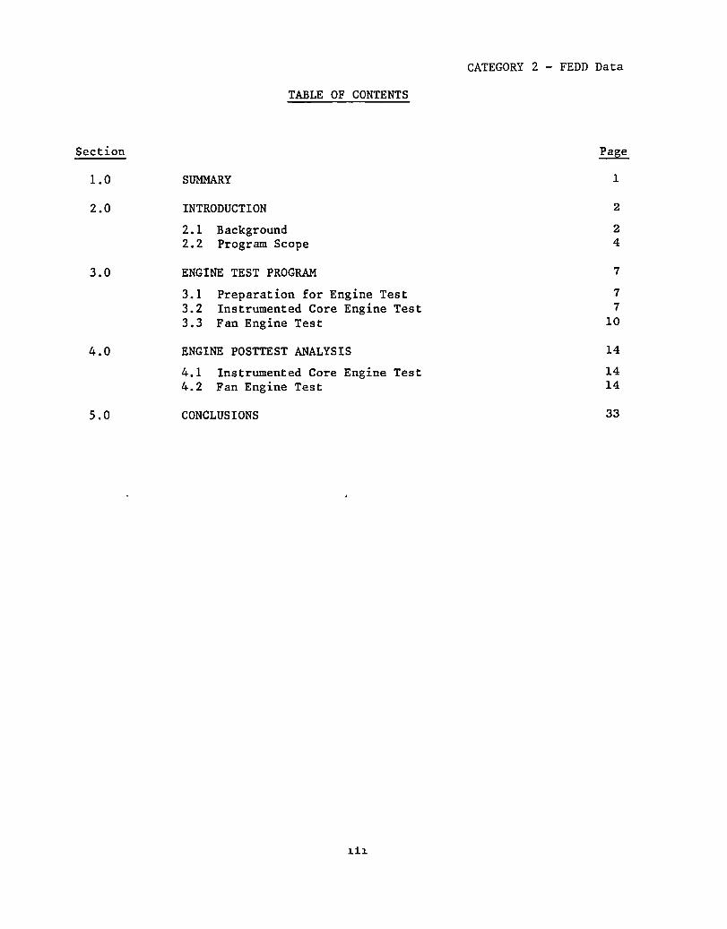
1.0 SUMMARY 1
2.0 INTRODUCTION 2
2.1 Background 2 2.2 Program Scope 4
3.0 ENGINE TEST PROGRAM 7
3.1 Preparation for Engine Test 7
3.2 Instrumented Core Engine Test 7
3.3 Fan Engine Test 10
4.0 ENGINE POSTTEST ANALYSIS 14
4.1 Instrumented Core Engine Test 14 4.2 Fan Engine Test 14
5.0 CONCLUSIONS 33

Figure
1.
2.
3.
4.
5.
6.
7.
8.
9.
10.
11.
12.
13.
14.
15.
16.
17.
18.
19.
CATEGORY 2 - FEDD Data
LIST OF ILLUSTRATIONS
Stress Rupture of Turbine Blade Alloys.
Rene 150 Directionally Solidified Superalloy Turbine Blade Project Plan.
Stage 1 Blade Strain Gage Locations.
Rene 150 CF6-50 Stage 1 HPT Blades Assembled in Rotor.
Comparison Between Temperatures of Rene 150 and Rene 80 Blade Designs.
Pyrometer Trace Showing Comparison Between Relative Temperatures of Rene 150 Blades and Other Blades in the Fan Engine.
CF6-50 Simulated-Service "c" Cycle.
Typical FFT Campbell Diagrams for Rene 80 and Rene 150 Turbine Blades.
Typical Rene 150 HPT Blade After 1000 "c" Cycle Engine Test.
Typical Rene 150 HPT Blade Tips After 1000 "c" Cycle Engine Test.
Nose-Hole and Pressure-Side, Film-Hole Cracking.
Typical Radial Cracks at Pressure-Side, Film-Cooling Holes.
Typical Radial Cracks at Leading-Edge Nose Holes.
Platform Cracks.
Platform Crack on Convex Side Near Leading Edge.
Typical Photomicrographs of Tip Oxidation.
Internal Blade Surface with Aluminide Coating.
Uncoated Internal Blade Surface.
Upper: Typical AC 402 Coating in Cooler Regions; Lower: AC 402 Coating in Intermediate Temperature Regions.
~v
3
6
8
9
11
12
13
15
17
18
19
20
20
22
23
23
24
24
26

CATEGORY 2 - FEDD Data
LIST OF ILLUSTRATIONS (Concluded)
Figure
20. AC 402 Coating in Hottest Regions.
21. Rene 150 Base Metal Gamma Prime Morphology as a Function of Increasing Temperature.
22.
23.
24.
25.
26.
Photomicrographs of Typical Radial Cracks at LeadingEdge Nose Holes.
Radial Leading-Edge, Nose-Hole Cracks.
Typical Platform Cracks.
Scanning Electron Micrographs of Fracture Surface of Radial Pressure-Side, Film-Hole Crack.
Scanning Electron Micrographs of Fracture Surface of a Platform Crack.
v
27
28
29
30
30
31
32
Table
I.
II.
CATEGORY 2 - FEDD Data
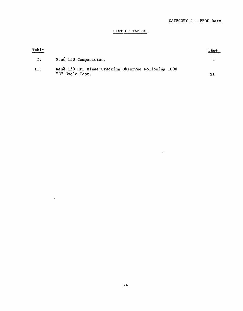
LIST OF TABLES
Rene 150 Composition.
Rene 150 HPT Blade-Cracking Observed Following 1000 "c" Cycle Test.
V~
Page
4
21

CATEGORY 2 - FEDD Data
1.0 SUMMARY
The objective of this project was to scale-up Rene 150, an advanced directionally solidified (DS) turbine blade alloy for application in the first stage high pressure turbine (HPT) blades of the CF6-50 engine. This scale-up was aimed at demonstrating the increased operating temperature capability of Rene 150 over Rene 80 that would allow for a 1.45% specific fuel consumption (sfc) saving in an advanced, variable-payload, commercial CF6-50 engine. The casting process was refined to indicate that such blades could be fabricated in production quantities at a cost not greater than 1.5 times the cost of conventionally cast (CC) Rene 80 turbine blades.
The processes required to produce the finished turbine blades were successfully developed and applied during Tasks I, II, III, IV, and VI of Project 2. The mechanical properties of the blade obtained in Task V met the requirements for core engine testing.
The instrumented Rene 150 HPT blades were successfully tested in a factory core engine. Analysis of strain gage data indicated that the Rene 150 blade provided a significant improvement in vibratory capability over the comparable Rene 80 blade and confirmed the suitability of Rene 150 blades for fan engine testing.
The Rene 150 Stage 1 HPT blades completed 1000 standard endurance cycles in a CF6-50 fan engine. This land-based test simulated typical operating conditions for this engine. The engine test was followed by dimensional analysis, visual inspection, and metallographic evaluation of selected blades. These evaluations revealed several long-term problems with the blade design utilized in this project. Rene 150 does not have adequate inherent oxidation resistance to take advantage of higher metal temperature capabilities. For a long-life blade design, the blade would have to be totally coated, and an oxidation resistant tip system would be required. In addition, the turbine blade cooling design would have to be adjusted to minimize the chordwise stresses produced at the higher temperatures. These activities were beyond the scope of this project.
CATEGORY 2 - FEDD Data
2.0 INTRODUCTION
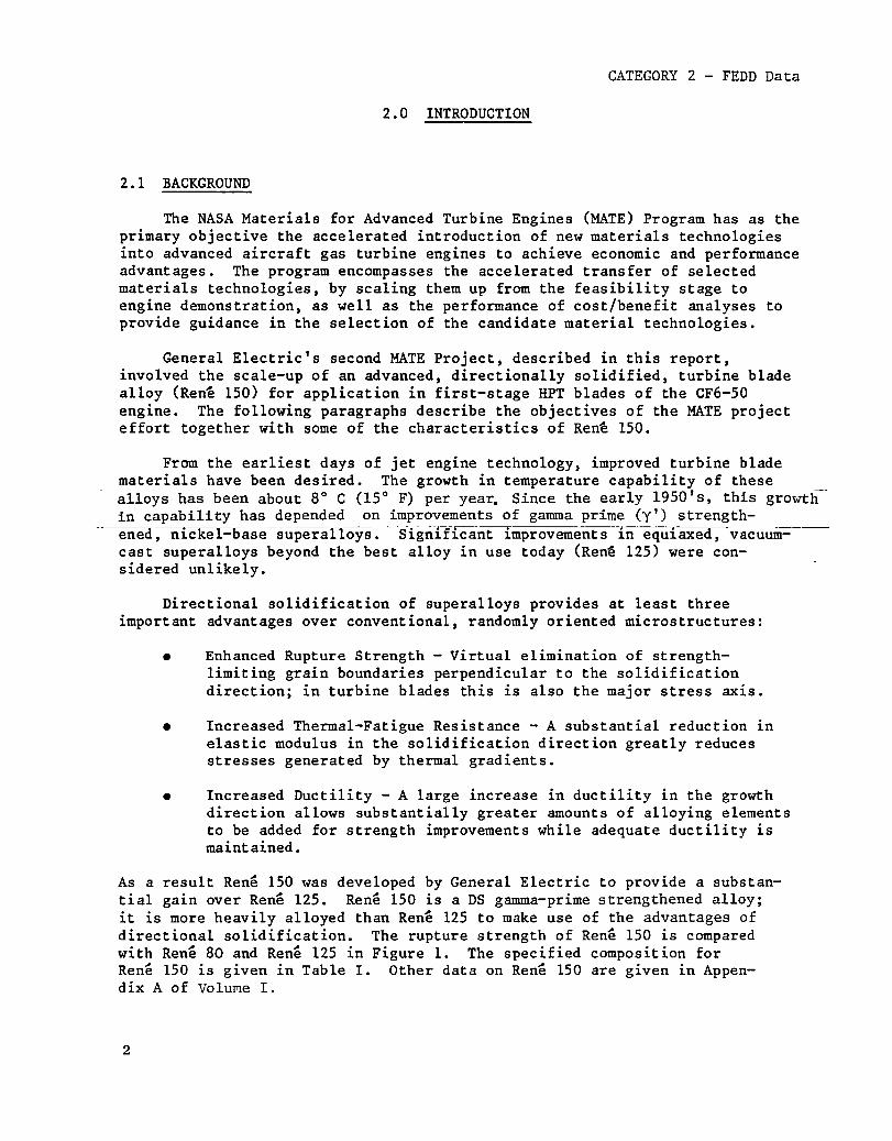
2.1 BACKGROUND
The NASA Materials for Advanced Turbine Engines (MATE) Program has as the primary objective the accelerated introduction of new materials technologies into advanced aircraft gas turbine engines to achieve economic and performance advantages. The program encompasses the accelerated transfer of selected materials technologies, by scaling them up from the feasibility stage to engine demonstration, as well as the performance of cost/benefit analyses to provide guidance in the selection of the candidate material technologies.
General Electric's second MATE Project, described in this report, involved the scale-up of an advanced, directionally solidified, turbine blade alloy (Rene 150) for application in first-stage HPT blades of the CF6-50 engine. The following paragraphs describe the objectives of the MATE project effort together with some of the characteristics of Ren~ 150.
From the earliest days of jet engine technology, improved turbine blade materials have been desired. The growth in temperature capability of these alloys has been about 8 0 C (15 0 F) per yea~ Since the early 1950's, this growth-in capability has depended on improvements of gamma prime (y') strength-
~ea~nickel-base superalloys. Significant improvements in equiaxed, vacuumcast superalloys beyond the best alloy in use today (Ren~ 125) were considered unlikely.
Directional solidification of superalloys provides at least three important advantages over conventional, randomly oriented microstructures:
• Enhanced Rupture Strength - Virtual elimination of strengthlimiting grain boundaries perpendicular to the solidification direction; in turbine blades this is also the major stress axis.
• Increased Thermal-Fatigue Resistance - A substantial reduction in elastic modulus in the solidification direction greatly reduces stresses generated by thermal gradients.
• Increased Ductility - A large increase in ductility in the growth direction allows substantially greater amounts of alloying elements to be added for strength improvements while adequate ductility is maintained.
As a result Rene 150 was developed by General Electric to provide a substantial gain over Rene 125. Rene 150 is a DS gamma-prime strengthened alloy; it is more heavily alloyed than Rene 125 to make use of the advantages of directional solidification. The rupture strength of Rene 150 is compared with Rene 80 and Rene 125 in Figure 1. The specified composition for Rene 150 is given in Table I. Other data on Rene 150 are given in Appendix A of Vo1u~e I.
2

(;J
600
I .. 80
Rene 150 '(L ongitudinal) I
500 I ~~ I •
Rene 150 ( I 400· - - .
( Transverse)
I -I 60
III
~ .. I CIl CIl S MAR-M200 Q) ~ ~ til 300 I I
j 50
40
200LI-----------4------------r- ~ I 30
l ______________ 1-____________ JL _______________ ~------------~~-------~~~~~~ 100 I
44 52 54 46 48 50 -3 P = T (20 + LOg t) x 10
Figure 1. Stress Rupture of Turbine Blade Alloys.
20
t/) n t1 ~ III Dl .. l'I" til ~
CJ
~ t'%J c;J 0
~ N
I
~ t::I t::I
t::I III rt III

CATEGORY 2 - FEDD Data
Table I. Rene 150 Composition, Weight Percent.
Element Nominal Weight, Percent
Chromium 5.0
Cobalt 12.0
Aluminum 5.5
Tantalum 6.0
Vanadium 2.2
Rhenium 3.0
Tungsten 5.0
Molybdenum 1.0
Hafnium 1.5
Carbon 0.06
Boron 0.015
Zirconium 0.03
Nickel Balance
Although General Electric had made excellent technical progress on Ren~ 150 development, a major scale-up effort was required to permit accelerated evaluation of this alloy for commercial service.
2.2 PROGRAM OUTLINE
The overall objective of General Electric's MATE Project 2 was to scaleup and engine test Ren~ 150, an advanced DS turbine blade alloy. The turbine engine component selected to demonstrate this technology was the firststage HPT blade of the CF6-50 engine. The blades were cast by the Rapid, Automated, Multistation (RAM)-DS process developed by General Electric. The target goals of this project were (1) to demonstrate an increased operatingtemperature capability, by using DS Rene 150 turbine blades, which would achieve at least 1.45% sfc savings in an advanced, variable-payload, commercial CF6-50 engine and (2) to refine a blade-casting process that would allow such blades to be produced in production quantities at a cost not greater than 1.5 times the cost of CC Rene 80 turbine blades.
4
The Program Task structure of Project 2 was as follows:
Task I
Task II
Task III
Turbine Blade Design and Analysis
Preliminary Rene 150 System Refinement
Coating Adaptation and Evaluation

CATEGORY 2 - FEDD Data
Task IV Final Rene 150 System Refinement
Task V Component-Test Blade Production and Evaluation
Task VI Engine-Test Blade Production
Task VII Engine Test
Task VIII - Posttest Analysis
Figure 2 is a flow chart showing the overall program structure. Note that a portion of Task V, Tasks VII,and VIII, covered the engine testing reported here. The results of Tasks I, II, III, IV, the remainder of Task V, and Task VI are presented under separate cover in Volume I of this report.
5

6
CATEGORY 2 - FEDD Data
TASK I TASK II Turbine Blade Design Prellmln.ry Rene 150
.nd An.lysls System Refinement
Prelimln.ry Design Alloy SC .... Up An.lylil .nd Ev.lu.llon
I Mold. Core Selecllon
I Blad~ Caslablhly TASK III
Evaluallon Coaling Adaptation .nd Evalu.tlon
rl CF6-5O Rene 150 Blade I I Prellmln.ry Design I I Ca.tlng TrI.11
Coating Adaptation to CF6-5O
Prelimln.ry C.lllng I Proc ... SpeclflCIIllon Co.tlng Evalu.tlon
Tooling Design Coating Procell , Speciflc.tlon
TASK IV Final Rene 150 Procell
Refinement
I Tooling Procu-.,t
I Final Dellgn
Ca.tlng Tri.11 I
Preproduction Run
I Procell
Specific. lion
y Engineering I I Drawing Prepared I I
TASK V Component-T .. t Blade
Production & Evaluallon
Blade Producllon J I -
Component T .. I I
I A:t" VI Engine T .. I
Blede Production I
TASK VII Engine T .. I
I TASK VIII
PosH .. 1 AnalySl.
Figure 2. Rene 150 Directionally Solidified Superalloy Turbine Blade Project Plan.

CATEGORY 2 - FEDD Data
3.0 ENGINE TEST PROGRAM
3. 1 PREPARATION FOR ENGINE TEST
The Rene 150 Stage 1 HPT blades for the CF6-50 engine tests were manufactured as described in Volume 1 of this report.
The blades for core engine testing were instrumented with high temperature, dynamic strain gages, as shown in Figure 3, so that the vibratory response of the Ren~ 150 blades could be measured and compared with the response of the Re~ 80 blades in the same rotating field. The strain gage locations were selected on the basis of the strain distribution testing performed in Task V. A like number of Ren~ 80 blades were similarly instrumented in order to provide the required data. None of the blades in this engine test were coated since this would interfere with the application and adherence of the instrumentation. The instrumented core engine test was then conducted.
Coated Ren~ 150 HPT blades were tested in a factory fan engine. Figure 4 shows several of the Ren~ 150 blades assembled into the HPT rotor prior to engine test.
3.2 INSTRUMENTED CORE ENGINE TEST
The instrumented core engine test was conducted, as a portion of Task V -Component Test Blade Production and Evaluation, to confirm the suitability of the Rene 150 Stage 1 HPT blade for fan engine testing. Nineteen uncoated Rene 150 blades were utilized in this test. The remaining 61 blades in the rotor were uncoated, CC Rene 80 blades. The purpose of the test was to obtain a back-to-back measure of the vibratory response of the Rene 150 and Rene 80 blades when they were exposed to the same engine-related sources of excitat~on. This was accomplished by instrumenting both types of blades, as discussed in Section 3.1, and then running them in the engine. .
- --- ~ -- - - - ~ --- -
The core engine is a factory engine without the fan and low pressure turbine (1PT) system. The inlet conditions to the engine were varied to simulate the conditions of pressure and temperature which would exist during normal operation in a fan engine.
The core engine was run for a total of 233 hours. There were a total of 70 cycles, and the engine speed was varied from idle (6,300 rpm) to 105% of maximum takeoff (11,250 rpm). The testing included fast and slow acce1s and dece1s, steady-state operation, "c" cycles, a hot rotor reburst, and a turbine imbalance test. During engine operation the strain gage, temperature, and engine operating data were continuously monitored and recorded on magnetic tape for subsequent evaluation and analysis.
7

CATEGORY 2 - FEDD Data
l .145
SD3
-$- -t--+----..
1.50
~J CONCAVE .74
CONVEX
Figure 3. Stage 1 Blade Strain Gage Locations.
8
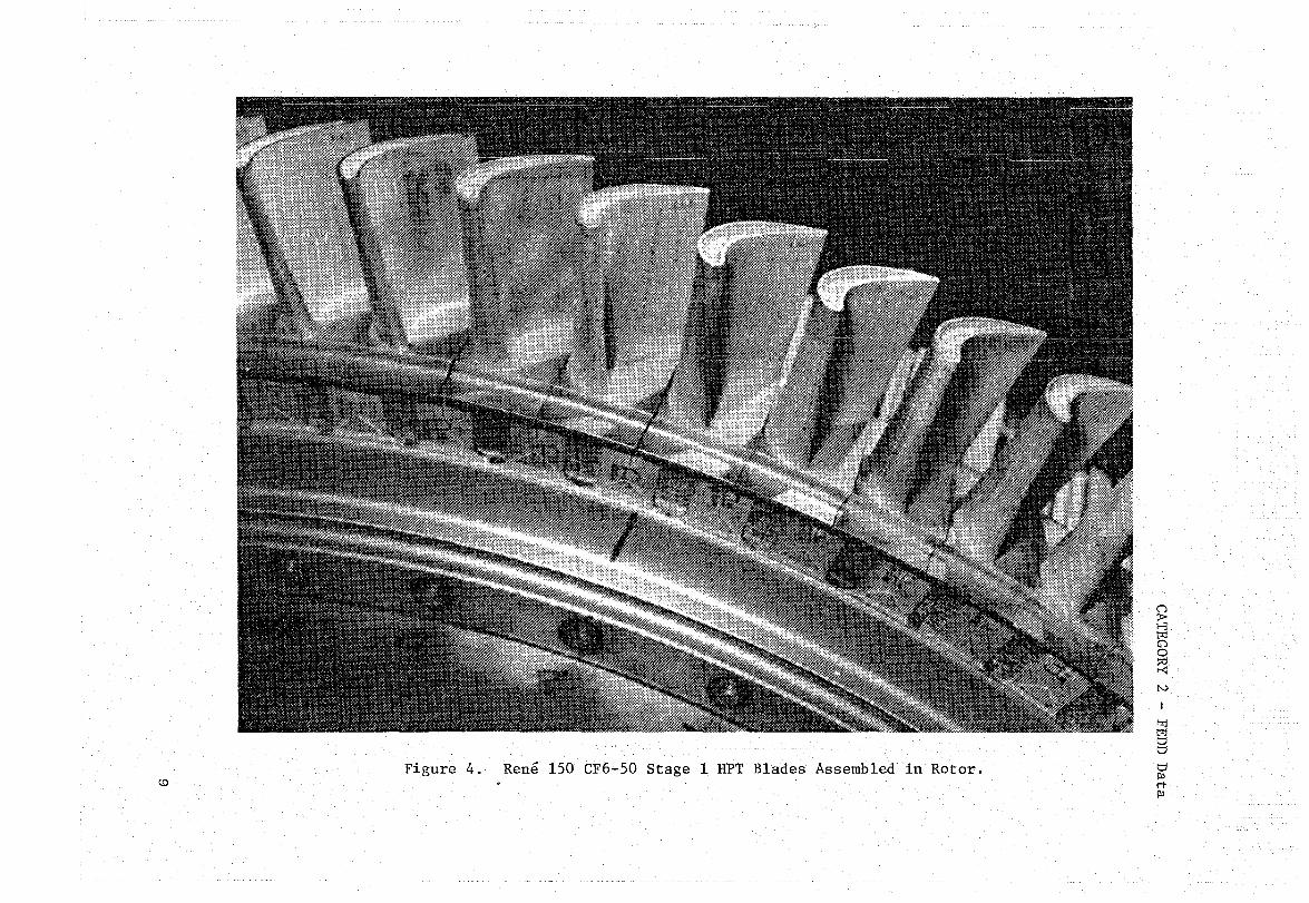
Figure 4. Rene 150 CF6-50 Stage 1 HPT Blades Assembled in Rotor. (0
&; I-,j t<:1 o o ~ N
I
'-rj t<:1 t:;j t::I
t:;j Pl rt Pl

CATEGORY 2 - FEDD Data
3.3 FAN ENGINE TEST
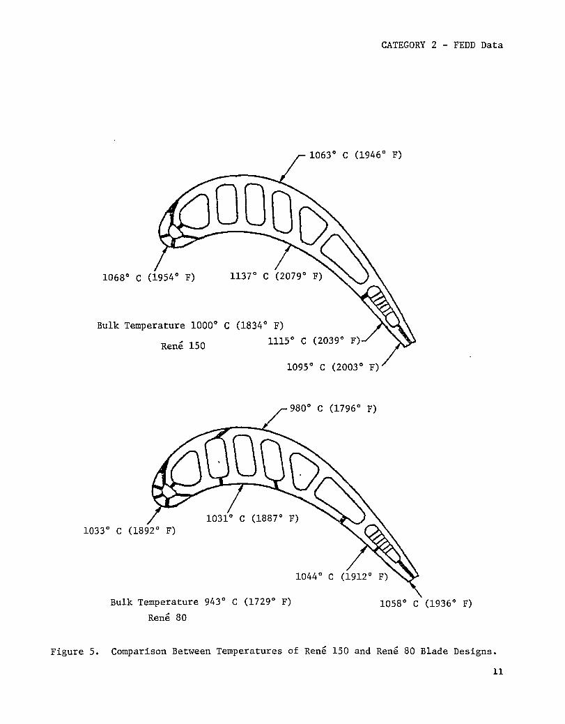
Thirteen Rene 150 CF6-50 Stage 1 HPT blades were utilized in the fan engine test. The intent of the test was to operate the Rene 150 HPT blades approximately 56° C (100° F) hotter than the comparable Rene 80 blades in order to demonstrate increased operating-temperature capability. The initial blade heat transfer analysis, Figure 5, indicated that this would be achieved. A pyrometer trace, Figure 6, taken during the initial engine calibration showed that the Rene 150 HPT blades were indeed operating at the desired relative temperature.
The remaining 67 blades in the HPT rotor were Rene 80. These blades were engine tested under standard "c" cycle conditions which simulate in a test cell the temperature, stress, and cyclic nature of actual engine operation on a commercial transport aircraft. Figure 7 shows a typical "c" cycle for the CF6-50 engine. This cycle includes ground idle, takeoff, climb, descent, and thrust reverse conditions. One thousand of these cycles were performed in a total of 250 hours of running time during the CF6-50 engine test of the Rene 150 HPT blades.
10
CATEGORY 2 - FEDD Data
1063° C (1946° F)
1068° C (1954° F)
Bulk Temperature 1000° C (1834° F)
Rene 150 1115°
1095° C (2003° F)
980° C (1796° F)
Bulk Temperature 943° C (1729° F)
Rene 80
1044°
1058° C (1936° F)
Figure 5. Comparison Between Temperatures of Rene 150 and Rene 80 Blade Designs.
11

12
Temperature ----.... Rene Rene Rene
Figure 6. Pyrometer Trace Showing Comparison Between Relative Temperatures of Rene 150 Blades and Other Blades in the Fan Engine. -
CATEGORY 2 - FEDD Data

I-' W
100
t ;:.:: ~ QJ s::
OM 00
~
~ OM ~
~ 4-l o
IN!
a
Takeoff
Climb
Approach
Fl1ght Idle
Idle
Max Motor1ng
Shutdown o 1 2
Take Reading
\ Reset Nl After 40 sec on Point
5-8 sec Throttle Advance
3-5 sec 30 sec
Throttle / Move Lim1ted by Reverse Stop
"".~r 8336 rpm Max
Starter Off
/ H
3 4 5 6 7 8 9 10 11 12 13 14 15 Time, Minutes
Figure 7. CF6-50 Simulated-Service "c" Cycle.
~ H t1j G1 o ~ N
I
"1 t1j t::I t::I
t::I III rt III
CATEGORY 2 - FEDD Data
4.0 ENGINE POSTTEST ANALYSIS
4.1 INSTRUMENTED CORE ENGINE TEST
Posttest analysis of the Rene 150 HPT blades from the instrumented core engine included visual and dimensional analyses but was primarily concentrated on evaluation of the strain gage data to confirm the suitability of the blade for fan engine testing.
The visual and dimensional analyses revealed no evidence of defects, distress, or distortion resulting from the engine test. The strain gage data obtained during the test were utilized in two ways. The first was the determination of the overall stress level produced in the blade by all of the vibratory modes present for each engine speed setting. The second was to produce Fast Fourier Transform (FFT) Campbell diagrams showing the spectral content of the overall signal as a function of engine speed.
The vibratory strain signals of both the Rene 150 and the Rene 80 blades were similar in magnitude and frequency content. However, the anisotropic properties of Rene 150, mainly the lower spanwise modulus, result in lower overall vibratory stress levels for the Rene 150 blade.
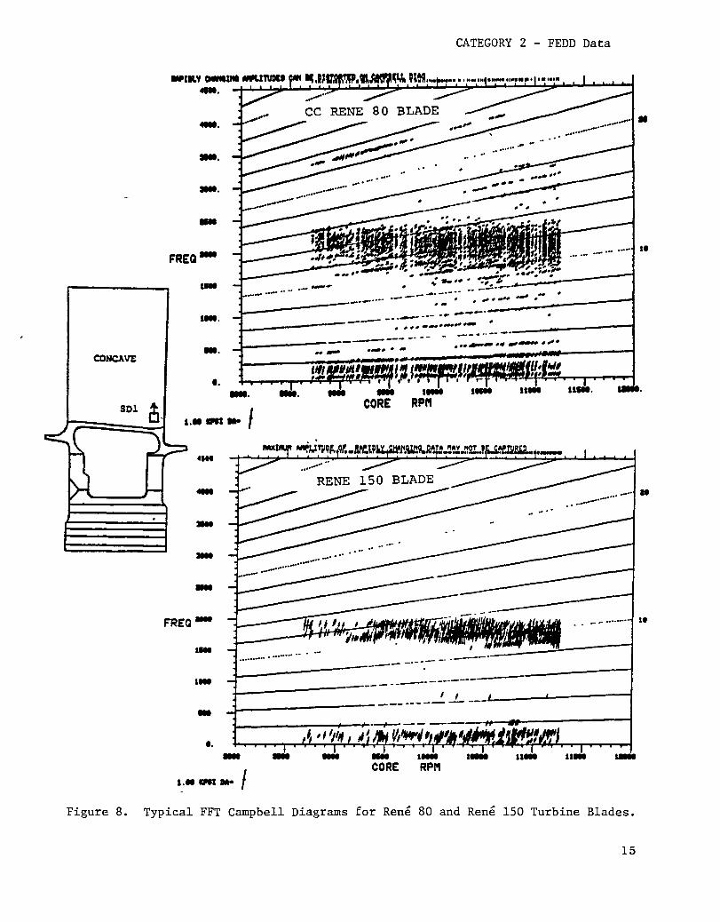
A typical FFT Campbell diagram is shown in Figure 8. These diagrams were used to determine which modes of excitation produced the majority of the overall vibratory stress. Utilizing these data in combination with the previously obtained strain-distribution data, it was possible to calculate the vibratory stress levels in all areas of the blade. This information was then used to establish the turbine blade vibratory stress severity or percent limit (defined as the ratio of the measured engine stress to the calculated allowable vibratory stress level).
The limiting location with respect to blade vibration is the area on the blade exhibiting the highest percent limit. Therefore, the areas of the blade which were evaluated were those with a combination of relatively high measured vibratory stress and low allowable stress. As discussed previously, the measured vibratory stresses were determined by analysis of the strain gage data. The allowable stress levels were determined from the Rene 150 Goodman dia-grams presented in Volume 1 of this report. that the Rene 80 blade would be operating at blade would be operating at 13% limit. This cant improvement in vibratory capability for justified the suitability of Rene 150 blades
4.2 FAN ENGINE TEST
Analysis of this data showed 48% limit while the Rene 150 confirmed the expected signiflthe Rene 150 HPT blade and for fan engine testing.
Posttest analysis of Rene 150 HPT blades from the fan engine test included dimensional analysis, visual examination, and metallographic evaluation of selected blades.
14
CONCAVE
CATEGORY 2 - FEDD Data
......
....
.... -
FREQ-
•••• ~#'" .-_ .. -.-. _.- .... --. ~" .. -, ... ~---.,. .. ~ .... L._----------- --; ···--·-:~_-----,---------1 ...
t. -. , .• ..a .. /
.....
...
... -
FREQ-... ...
CORE RPI'I
...... -. ......... . ---- ..
-- ----- ------.. i-----'--...l------------ ------' .1- ___ .L-_--..----i
t. -, ..• IN1 ... I CORE RPI'I
Figure 8. Typical FFT Campbell Diagrams for Rene 80 and Rene 150 Turbine Blades.
15
•
••
Ie
CATEGORY 2 - FEDD Data
Dimensional analysis of the Rene 150 blades revealed no evidence of trailing-edge bowing or other dimensional distress associated with the higher temperatures at which they operated.
The visual examination was performed on all of the blades from the rotor using 40X binoculars. The blades were inspected for oxidation, cracking, coating distress, and dovetail wear patterns. Figure 9 shows a typical Rene 150 HPT blade following the completion of the fan engine test. All of the blade airfoils were covered by a very thin iron oxide deposit; this is a normal occurrence in Evendale factory engine tests. All blades exhibited evidence of distress.
As expected, the Rene 150 blades exhibited much more tip oxidation than the Rene 80 blades. Figure 10 illustrates the extensive metal loss that occurred on the Rene 150 blades and left the coating in relief in a worstcase situation. In addition, the Rene 150 blade platforms and shanks were oxidized on the pressure side of the blade. The Rene 80 blades exhibited no oxidation in this region. The AC 402 blade coating showed no obvious signs of distress.
All of the blades in the rotor contained radial cracks emanating from the nose, concave film and concave gill holes; however, the cracks in the Rene 150 blades were more frequent and extensive. Table II presents the cracking summary for the Rene 150 HPT blade. Figures 11, 12, and 13 show typical examples of the observed cracking. The Rene 150 and the Rene 80 blades exhibited similar platform cracking in terms of location and extent. Several examples of this are shown in Figures 14 and 15. The dovetail wear patterns were similar on both the Rene 150 and Rene 80 blades.
Following these examinations, four representative Rene 150 HPT blades were selected for destructive metallographic evaluation. To facilitate examination, the iron oxide deposits were removed from two of the blades by cleaning in a very mild alkaline solution and then vapor blasting. This type of cleaning is not detrimental to either the coating or the base metal, but to ensure that there were no complications with regard to subsequent fractographic or microscopic interpretations it was not employed on all four blades. The blades were then sectioned for microscopic examination of the visually observed regions of blade distress.
The tip oxidation progressed radially downward from the tip, Figure 16, and was present on all tip sections. It was heaviest on the concave side of the blade near the trailing edge where it reached apparent depths of 40 mils or more. The oxidation was usually most extensive nearest the blade external surface and did not entirely consume the coating.
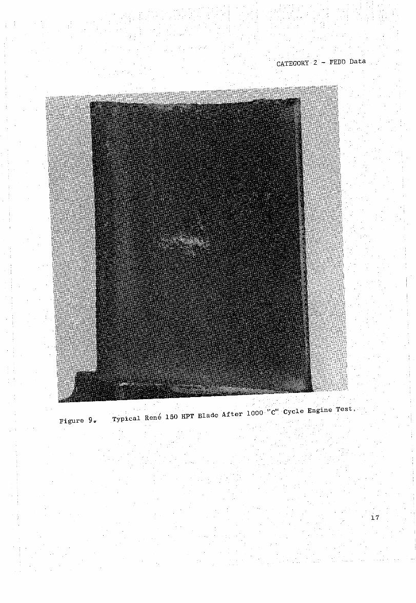
The internal blade surfaces that were aluminide, as a consequence of the coating operation exhibited no base-rnetal attack and minimal coating attack as shown in Figure 17. However, the uncoated internal surfaces were oxidized to various degrees as shown in Figure 18. The heaviest oxidation, approximately 3 mils deep, was observed in the concave side midspan/midchord area of the blade.
16
CATEGORY 2 - FEDD Data
Figure 9. Typical Ren' 150 HPT Blade After 1000 tt~' Cycle Engine Test.
17

Figure 10. Typical Ren~ 150 HPT Blade Tip After 1000 "Cft Cycle Engine Test.

CATEGORY 2 - FEDD Data
Concave - Note Cracks at Pressure Side Holes
Leading Edge . Leading Edge Hole Cracks
Figure 11. Nose-Hole and Pressure-Side, Film-Hole Cracking.
19

tv o
3,1.75 11m
Figure 12. Typical Radial Cracks at Pressure-Side, Film-Cooling Holes.
I 3,175 11m
Figure 13. Typical Radial Cracks at Leading-Edge Nose Holes.

1.
2.
3.
4.
5.
CATEGORY 2 - FEDD Data
Table II. Rene 150 HPT Blade Cracking Observed Following 1000 "c" Cycle Test.
Location Cracking Observed
Leading-Edge Nose Holes
Pressure-Side Gill Holes
Pressure-Side Film Holes
Suction-Side Gill Holes
Platform
All 13 blades exhibited radial cracking in convex row of nose holes. Total number varied from 5 to 16 cracks with the most severe cracks between holes 8 to 12. Two blades had a cracked hole in the concave row.
Seven blades exhibited radial hole cracking not confined to any particular region. Total number of cracked holes varied from 1 to 18.
All 13 blades exhibited radial cracking. Holes below No. 8 generally cracked from top and bottom of hole; above No. 8 cracked from bottom only. Total number of cracked holes varied from 7 to 12. Six blades had two or more holes connected by cracks, and these were found between holes 5 to 8 only.
No apparent cracking.
Ten blades contained cracks on the convex side platform. six blades were cracked just forward of the high C location and four just aft. On seven of the blades, the cracks extended to the airfoil fillet radius.
21

22
CATEGORY 2 - FEDD Data
3,175]lm I
Platform Crack on Concave Side Near Leading Edge
3,175]lm I
Platform Crack on Convex Side Near Leading Edge
Figure 14. Platform cracks.

CATEGORY 2 - FEDD Data
2822 11m
Figure 15. Platform Crack on Convex Side Near Leading Edge.
846.6 11m
Forward of Trai~ing Edge/ Concave Side
Phosphoric Etch
Midchord Concave Side
Phosphoric Etch
(Note That Coating on External Surface is in Relief)
423 11m
Figure 16. Typical Photomicrographs of Tip Oxidation.
23
CATEGORY 2 - FEDD Data
63.5 ~m
Figure 17. Internal Blade Surface with A1uminide Coating.
Concave/Tip Area Concave/Midspan
(External Surface is to Left)
Figure 18. Uncoated Internal Blade Surface.
24

CATEGORY 2 - FEDD Data
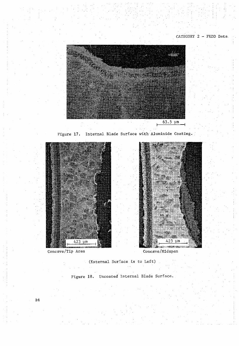
The AC 402 coating was in generally good condition with a typical thickness of 3 to 4 mils. The airfoil operating temperature was characterized by the pattern ~f coating changes as shown in Figures 19 and 20. The hottest regions of the blade exhibited the more extensive coating transformation; the coolest regions exhibited negligible transformation. No coating/base-metal separations were evident. Aside from the slight surface oxidation and tip attack discussed previously, there was no significant environmental attack of the coating.
The actual base-metal temperatures attained during the test were not determinable; however, a microstructural pattern was observed in the Rene 150 which was consistent with that described for the coating. As shown in Figure 21, the hottest regions of the blade exhibited the coarsest y', and the coolest areas exhibited normal y' size and morphology.
In addition, no recrystallization was observed in any blade section. The special precautions taken during the blade manufacturing sequence to prevent recrystallization were successful.
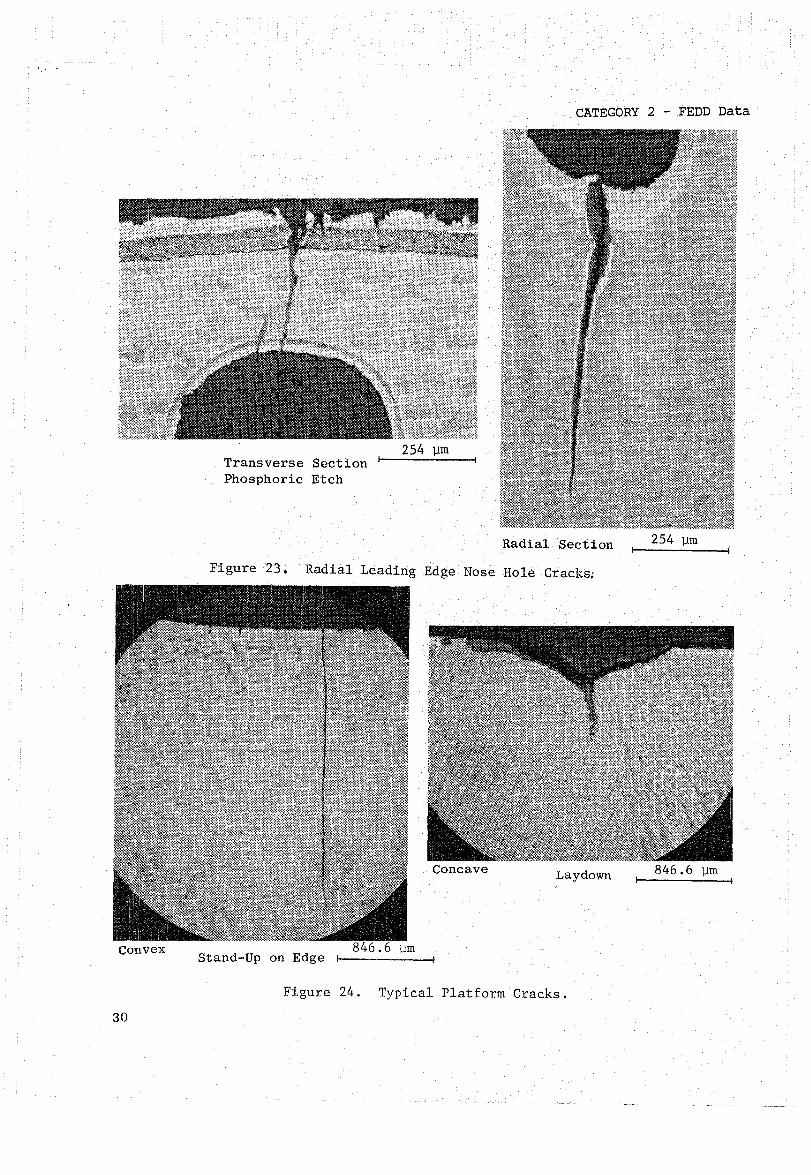
Meta110graphic evaluation of the cracks observed at the nose holes, concave cooling holes, and in the platform showed that they were typical thermal-fatigue cracks. They were characterized by a predominantly transgranu-1ar crack path and associated oxidation and alloy depletion as shown in Figures 22, 23, and 24. A fractographic evaluation of several of the cracks was performed by breaking open the blade and examining the fracture surface with a scanning electron microscope (SEM). Even though the crack fracture surfaces were heavily oxidized, it was possible to observe evidence of fatigue propagation near the crack extremities as shown in Figures 25 and 26. The airfoil cracks did not extend through the wall thickness in any location. The platform cracks extended completely through the platform edges. These exhibited less alloy depletion and oxidation than the airfoil cracks (indicative of a lower operating temperature).
25
26
CATEGORY 2 - FEDD Data
63.5 '11m -
63.5 '11m
(Note Transformation to y Particularly in Inner Layer and and Increase in Coating Thickness Due to Diffusion).
Figure 19. Upper: Typical AC402 Coating in Cooler Regions Lower: AC402 Coating in Intermediate Temperature Regions.

CATEGORY 2 - FEDD Data
63.5 11m
(Note Significant Transformation to y and Increase in Thickness).
Figure 20. AC402 Coating in Hottest Regions.
27

28
63.5 11m
CATEGORY 2 - FEDD Data
Normal y I
Coarser yl (Concave - Midchord/ Trailing Edge, Mid-Span to Near Tip and Convex - Tip/Trailing Edge Area)
Coarsest Y~(Concave - Midchord/ Trailing Edge Area)
Figure 21. Rene' 150 Base Neta1 Gamma Prime Morphology As A Function of Increasing Temperature.
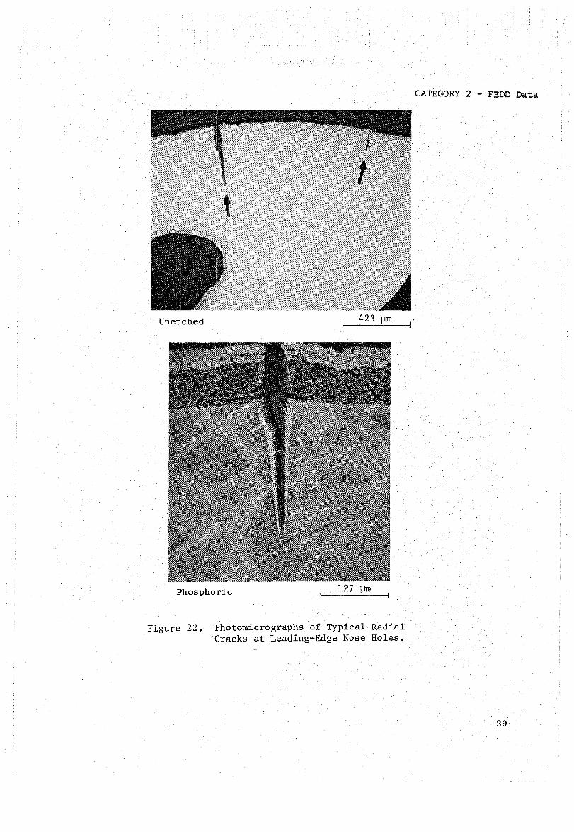
Unetched 423 ]Jm
Phosphoric 127 ]Jm
Figure 22. Photomicrographs of Typical Radial Cracks at Leading-Edge Nose Holes.
CATEGORY 2 - FEDD Data
29
30
CATEGORY 2 - FEDD Data
Transverse Section ~I----------~ Phosphoric Etch
Radial Section
Figure 23. Radial Leading Edge Nose Hole Cracks;
Concave Laydown
Stand-Up on Edge ~I ----------~
Figure 24. Typical Platform Cracks.
254 11m

CATEGORY 2 - FEDD Data
SEM 2540 ~m
SEM 12.7 ~m
Arrows Denote Depth (Rest is Lab Break)
S~
Crack
6.35 ~m
External Airfoil Surface is to the Right; Direction of Crack Propagation is to Left. Note Evidence of Fatigue Propagation Near Crack Extremity.
Figure 25. Scanning Electron Micrographs of Fracture Surface of Radial Pressure-Side, Film-Hole Crack.
31

CATEGORY 2 - FEDD Data
5,644 11m I
Convex Platform Crack Fracture Surface - Depth Denoted by Arrows (Rest is Lab Break and Saw Cuts).
SEM 25.4 11m
SEM 635 11m
SEM 8.47 11m
Note Evidence of Fatigue Propagation in Area of Maximum Crack Depth (Arrows).
32
Figure 26. Scanning Electron Micrographs of Fracture Surface of a Platform Crack.
CATEGORY 2 - FEDD Data
5.0 CONCLUSIONS
The Rene 150 HPT blades successfully completed both the instrumented core engine test and the 1000 "c" cycle factory fan engine test.
Analysis of the data from the instrumented core engine test confirmed that the Rene 150 blade had adequate vibratory capability and was suitable for fan engine testing.
The fan engine test was successfully run, and the Rene 150 HPT blades operated at the desired 56° C (100° F) temperature increment above the Rene 80 blades; however, the posttest analysis of the blades revealed several potential long-term problems with the blade design utilized in this project. A long-life blade design would have to be coated on the inside and outside including the shank and dovetail regions. In addition, an oxidation-resistant tip would be required.
For this test, no attempt was made to efficiently utilize the blade cooling air. The primary objective was to achieve the increased operating temperature without endangering the fan engine test. At the higher operating temperatures allowed by Rene 150 longitudinal properties, radial cracking may become the limiting factor. The blade cooling design would have to be adjusted to minimize the chordwide stresses produced at the higher temperatures. This additional coating development, tip treatment, and total blade redesign were beyond the scope of the current project.
33

End of Document


