
Technology of Hot Rolled Mild Steel Sheets & Steel Strips(Formability, Fatigue property and Spot weldability of SPHC Steel)
Steel SheetsHot Rolled Coils
2016.10.01
T o k y o S t e e l M a n u f a c t u r i n g C o . , L t d .

Hot Rolled Mild Steel Sheets & Steel Strips
2016.10.01
1. Introduction
2. Characteristics of manufacturing process
3. Data of quality
3.1. Chemical composition and mechanical property
3.2. Press formability (CCV, LHER, Erichsen, and LDR)
3.3. Press formability ( FLD )
3.4. Fatigue property
3.5. Spot weldability
3.5.1. Range of suitable welding current
3.5.2. Evaluation of joint strength
Contents
・・・・・・・・・・・・・・・・・・・
・・・・・・・
・・・・・・・・・・・・・・・・・・
・・・
・・・・
・・・・・・・・・・・・・・
・・・・・・・・・・・・・・・・・
・・・・・・・・・・・・・・・・・
・・・・・・・・
・・・・・・・・・・・
3
5
6
6
7
11
13
14
14
16

1 Intro
du
ctio
n
3
PAG
EPA
GE
Introduction
Fig.1 Amount of carbon dioxide emissions and amount of energy consumption under production
References:1) Makoto Nishino: “Theoretical evaluation of CO2 emission by integrated steelmakers”, Ferrum, Vol.3, No.1
(1998),p.232) Environmental Affairs Group, the Japan Iron and Steel Federation: Efforts against environmental problems in steel
manufacture industry, Tekkokai (1992), p.243) Agency for Natural Resources and Energy, Ministry of Economy, Trade and Industry and the Japan Iron and
Steel Federation: Energy evaluation study for use of steel products seen from LCA viewpoint
Comparison of the amount of carbon dioxide emissions Comparison of energy consumption
Electric furnace Electric furnace
Blast furnace 1) Blast furnace 2)Blast furnace 3)
❶ Introduction
The Okayama Plant of Tokyo Steel started the production of hot-rolled mild steel strips from electric furnace steel by introducing the leading-edge DC electric furnace-hot strip mill in October 1991. We also introduced the continuous pickling line in 1995, cold rolling mill and surface treatment line in 1997 and leveller/shear line in 2004 to address the current manufacture of hot-rolled mild steel sheets and strips, pickled steel sheets and strips, hot-dip galvanized steel strips. By studying and developing the technology to effectively utilize the tramp elements (traveling elements) such as Cu which increase in volume as the number of recycling count grows while utilizing the accumulated operation know-how, we provide high-quality and environmentally friendly electric furnace steel materials that suit the needs in a wide range of fields including industrial machines, home appliances and automobiles.
Tokyo Steel’s Views to Global WarmingSource: Home Page, Tokyo Steel Manufacturing Co., Ltd.
In 1997, the Kyoto Protocol became the world’s first international agreement on the issue, producing commitments by principally European countries and Japan to reduce their CO2 emissions in 2012 by about 5% compared with 1990. Further discussions have been continued at the summits and international conferences, trying to determine additional and stricter targets, and to fashion a system in which all nations can participate.Taking action against global warming is the responsibility of current generations. We must act now to reduce CO2 emissions and develop the alternatives for fossil fuels to preserve the Earth's environment.In Japan, the CO2 emissions of the steel industry account for a little over 14% of the total (FY2008), the highest proportion among all the industries. Since steel is essential for the society to achieve industrial development, there is a clear need to find a way to reduce CO2 emissions in manufacturing steel.There is a big difference in CO2 volume between two methods being used to manufacture steel; making one ton of steel through a blast furnace method using iron ore and coal as its main feeds emits two tons of CO2 compared with less than 0.5 tons by an electric furnace method which is making steel through recycling of steel scrap. For manufacturing exactly the same type of steel, the CO2 emissions from an electric furnace mill are one fourth of those by a blast furnace mill.In 1995, we brought the Utsunomiya works on stream, establishing basically almost the same product lineup and capacity that Tokyo Steel has today. During the 15 years since FY1995, we have got about a 440-thousand-ton yearly average reduction in CO2 emissions over the 15 years through replacing a supply of steel products which had been produced by the blast furnace mills. Therefore, we consider that Tokyo Steel has actually achieved a reduction in CO2 emissions equivalent to 35% of its FY1990 CO2 emissions, which is evidently a huge reduction compared With the 5% target set for Japan as a whole under the Kyoto Protocol.When we consider a substantial reduction of CO2 emissions, recycling of steel scrap should be further promoted in Japan.
Hot Rolled Mild Steel Sheets & Steel Strips 2016.10.01

4
PAG
EPA
GE
1 Intro
du
ctio
n
Introduction
electric furnace
iron ore
FeFeFe
2.3(CO2 ton/steel ton)※1
0.53(CO2 ton/steel ton)※1
from Brazil 0.37(CO2 ton/steel ton)※3from Australia 0.11(CO2 ton/steel ton)※3
0.003(CO2 ton/steel ton)※2
0.003(CO2 ton/steel ton)※2
in Japan
overseas
blast furnace
Fig.2 Amount of CO2 emissions per one ton of steel (products) accompanying recycles of steel
References:
※1 Makoto Nishino: “Theoretical evaluation of CO2 emission by integrated steelmakers”, Ferrum, Vol.3, No.1
(1998), p.23.
※2 In case of 50km land transportation after Ministry of Economy, Trade and Industry and Ministry of Land,
Infrastructure, Transport and Tourism: “A guideline for a calculation method on CO2 emissions in transport sector”
(http://www.enecho.meti.go.jp/policy/images/060518pamph.pdf)(2010), p.6.
※3 Ship & Ocean Foundation: “A report on research concerning the reduction of CO2 emission from vessels” August
2000 (assuming that the iron content of iron ore is 60%, Japanese version p.92).
Hot Rolled Mild Steel Sheets & Steel Strips 2016.10.01

2 Ch
ara
cte
ristics o
f ma
nu
fac
turin
g p
roc
ess
5
PAG
EPA
GE
Characteristics of manufacturing process
continuous casting machinedegasserladle furnaceelectric furnace rougher mill
STF finishing tandem mill Rapid cooling equipment winding device
heating furnaceslab
DC furnace steel making plant
hot coil
shipping
skin-passwelder acid bath
pickling line
oiler
(oiling)(welding)
pickled coil cut sheetleveller shear line
zinc-coated coilcold roll mill
(reverse cold roll mill)surface treatment line
Fig.3 Process drawing ( Flowchart )
skin-pass tension leveller
zinc pot
(welding)welder an
neal
ing
furn
ace
allo
ying
furn
ace
(anti-corrosive)chromating coater
❷ Characteristics of manufacturing processHot rolled mild steel sheets and steel strips by Tokyo Steel are produced by using:
1) A large direct current electric furnace with eccentric bottom tapping (EBT)・ Steel scrap is melted homogenously and efficiently by optimized arrangement of electrodes.・ Low inclusion and low nitrogen content of steel are obtained by EBT
While minimizing the mixture of impurities such as inclusion by EBT, we reduce the mixture of nitrogen to manufacture clean liquid steel.
2) Steel refining at ladle furnace・ Homogeneity of chemical compositions is obtained by stirring Ar-bubbling.・ Quality of continuously cast slab is stabilized by temperature control.
3) Continuous casting・ Reduction in inclusion and improvement of internal quality of slab is obtained by complete
insulating from the air.4) Hot strip mill
・ Improvement in surface quality by ultrahigh-pressure water descalingWe set up the descalers at the entrance and the exit side of a rougher mill and also at the entrance side of a finishing tandem mill. They remove the scales generated on the rolling material surface.
・ Improvement of the precision of thickness of steel sheets by a coil boxWe wind steel plates before entering a finishing mill and equalize the temperature all over the materials in order to reduce the disturbance due to temperature difference and improve the sheet thickness precision.
・ Microstructural optimization of steels by TMCP ( Thermo-Mechanical Control Process )We can obtain the required microstructures and mechanical properties by controlling the cooling patterns over a run-out table.
As described above, we can apply the most suitable conditions to production by using various high advanced steel making facilities and hot strip mill. And we can manufacture high quality steel products with excellent mechanical property, formability, and weldability.
Hot Rolled Mild Steel Sheets & Steel Strips 2016.10.01
3 Data o
f quality
6
PAG
EPA
GE
Data of quality
0.1mm
❸ Data of quality This document introduces the characteristics of SPHC steel including the formability, fatigue property and spot weldability.
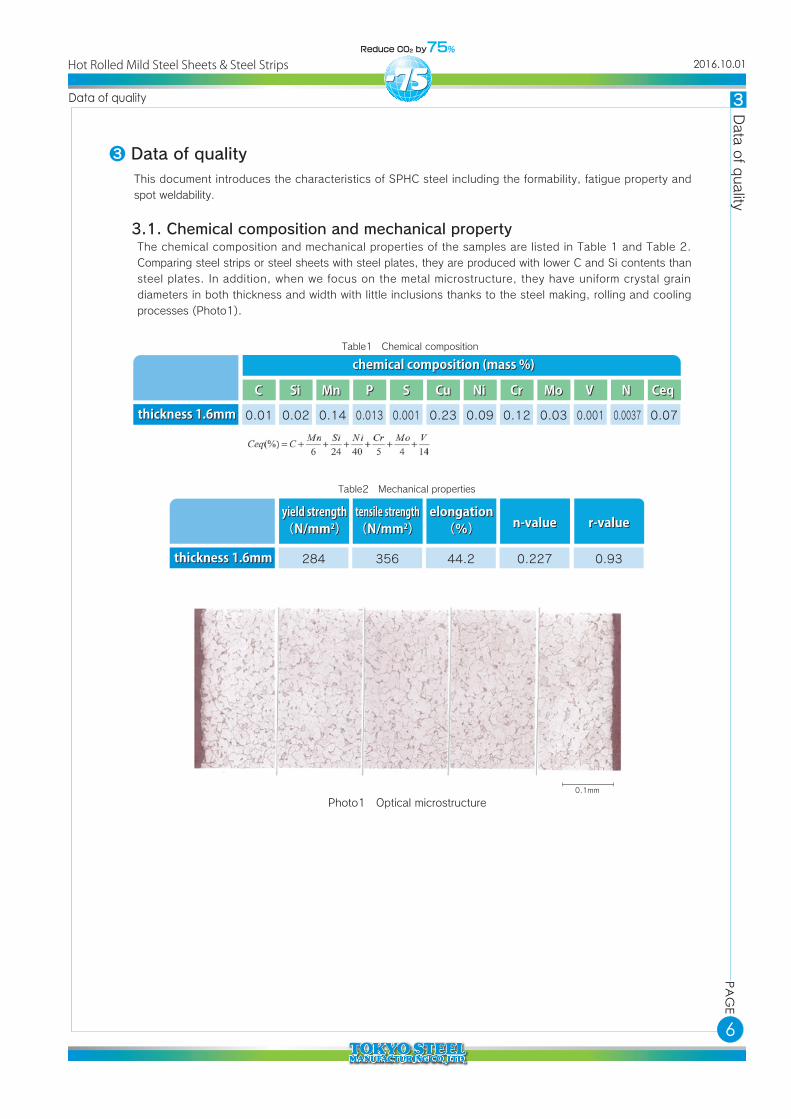
3.1. Chemical composition and mechanical propertyThe chemical composition and mechanical properties of the samples are listed in Table 1 and Table 2. Comparing steel strips or steel sheets with steel plates, they are produced with lower C and Si contents than steel plates. In addition, when we focus on the metal microstructure, they have uniform crystal grain diameters in both thickness and width with little inclusions thanks to the steel making, rolling and cooling processes (Photo1).
chemical composition (mass %)chemical composition (mass %)
CC SiSi MnMn PP SS CuCu NiNi CrCr MoMo VV CeqCeq
0.01 0.02 0.14 0.013 0.001 0.23 0.09 0.12 0.03 0.001
NN
0.0037 0.07thickness 1.6mmthickness 1.6mm
yield strength(N/mm2)yield strength(N/mm2)
tensile strength(N/mm2)tensile strength(N/mm2) n-valuen-value
284 356 0.227
r-valuer-value
0.93
elongation(%)
elongation(%)
44.2thickness 1.6mmthickness 1.6mm
Table1 Chemical composition
Table2 Mechanical properties
Photo1 Optical microstructure
Hot Rolled Mild Steel Sheets & Steel Strips 2016.10.01

7
PAG
EPA
GE
3 Data o
f quality
Data of quality
Drawability is improved as the value of work hardening coefficient (n-value) is larger because elongation until localized shrinkage occurs is large. It becomes the indicator for whether the material excels in bulging/strain uniformity during pressing. The general value for mild steels in market ranges about 0.15 to 0.25.
The ratio value between sheet width strain and sheet thickness strain which is also called plastic anisotropy or Lankford value, and deep drawability is higher as this value is larger. The general value for hot rolled sheets and strips in market ranges 0.80 to 0.95.
A test combining deep drawing and bulging deformation (composite formability test).
One of the stretch-flanging tests to test how easy it is to form with tensile deformation of the flange edge and inside as the deformation mode.
The amount of stretching when the center of the sheet is pushed up with a punch with the edges held and the sheet suffers fracture is called the Erichsen value and it is an indicator for evaluating the bulging formability (forming with biaxial tension deformation).
A method for deep drawing (shrink-flanging deformation) property testing and it is an indicator for how easy it is to form by drawing into the die hole by punching force with flange deformation by tension and compression.
A test to evaluate how easy it is to form by bending with approximate plane strain deformation and crack generation is checked after carrying out specified radius bending.
3.2. Press Formability(CCV, LHER, Erichsen, and LDR)The deformation modes in press forming can be classified as deep drawing, bulging, stretch-flanging and bending as shown in Fig.4. The relationship as shown in Table 3 is observed between these deformation modes and the characteristic values of the material.
n value Tensile test
r value
Conical cup value( CCV )
Limiting holeexpansion ratio
(LHER)
Erichsen value
Limiting drawingratio
(LDR)
Bendability
Tensile test
Conical cup test
Hole expandingtest
Erichsen test
Deep drawabilitytest
Bend test
Characteristic valueCharacteristic value Test methodTest method PointsPoints
Table3 Characteristic value and test method
Fig.4 Schematic illustration of typical defomation
deep drawingdeep drawing
stretch-flanging,outflow
stretch-flanging,outflow
diedie
diedie
stretchstretch
stretchstretchstretchstretch
outflowoutflow
outflowoutflow
stretchstretch
punchpunch
inflowinflow
stretchstretch
shrinkshrink
bulgingbulging
bendingbending
Hot Rolled Mild Steel Sheets & Steel Strips 2016.10.01

8
PAG
EPA
GE
3 Data o
f quality
Data of quality
form into a conical cup shape until the bottom breaks
da
D0
d2
2θ
rdru
d0
D0
rpcrack
outer diameter of cup D0 when cracking
rp
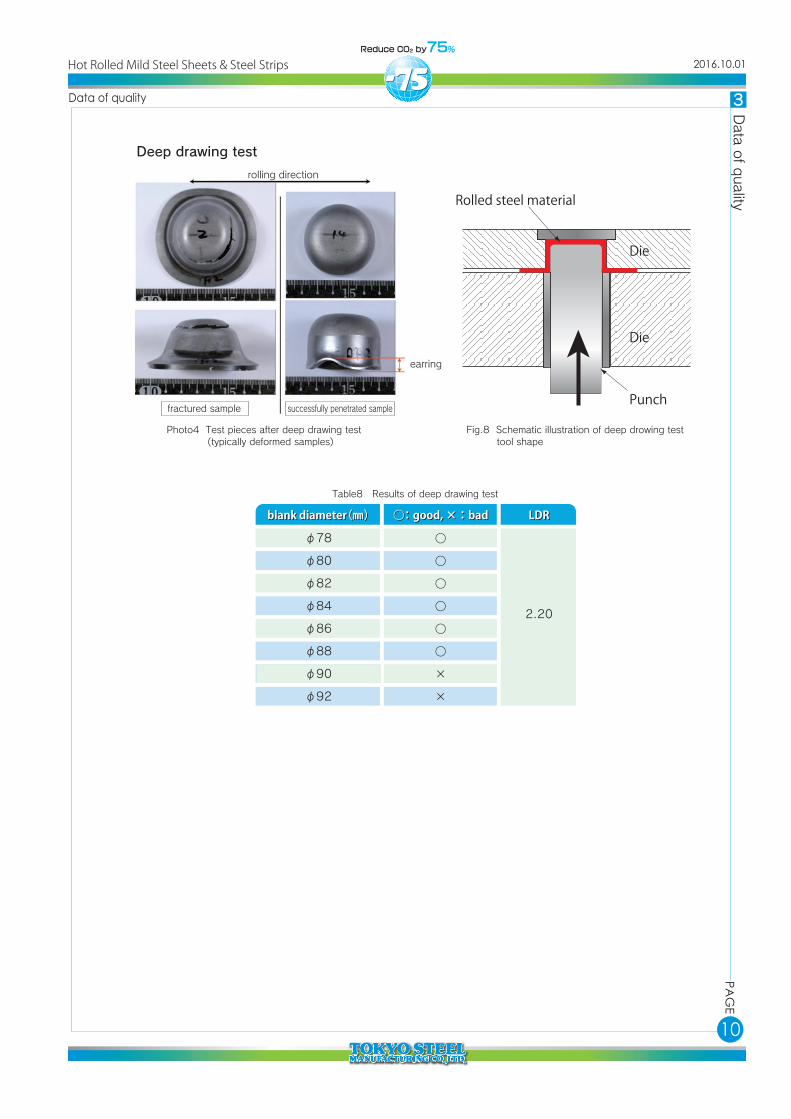
For press formability test, we have carried out conical cup test, hole expansion test, Erichsen test, and deep drawing test. Table 4 and Tables 5 to 8 list the conditions for each test and the test results, respectively. The SPHC steel by Tokyo Steel exhibits the excellent workability including 203% hole expansion ratio and 2.20% limiting drawing ratio.
JIS Z 2243
JFS T 1001(1996)
JIS Z 2247
-
27 model φ78
100×100(die inside diameterφ10.4mm)
100×100mm
φ78~92mm
machining oil
no lubricant
graphite grease
Daphne SK
10mm/min
20mm/min
10mm/min
25mm/min
none
9.0ton
1.0ton
2.0ton
Conical cup
hole expansion
Erichsen
deep drawing
test itemtest item methodmethod test piecetest piece lubricantlubricant work speedwork speed blank holding forceblank holding forceTable4 Conditions for tests
Fig.5 Schematic showing tool and specimen dimensions for the conical cup test
Conical cup test
61.15
61.07
61.14
60.82
60.82
61.06
60.99
60.85
61.10
61.0
1
2
3
samplesample max (mm)max (mm) min (mm)min (mm) CCV (mm)CCV (mm) average (mm)average (mm)Table5 Results of conical cup test
Hot Rolled Mild Steel Sheets & Steel Strips 2016.10.01

9
PAG
EPA
GE
3 Data o
f quality
Data of quality
die shoulder R
die hole diameterafter fractured
die diameter burr
test piece thickness
holding forceinitial holediameter
punch
There are two kinds for the punch: conical and cylindrical types
Fig.6 Conical type Photo2 Test pieces after hole expansion test (cylindrical type)
Fig.7 Schematic illustration of erichsen test tool shape
Table6 Results of hole expansion test (Comparison with other companies)
Photo3 Test piece after Erichsen test
Hole expanding test
Erichsen test
magnification
210.4 , 206.5 , 192.4
175.9 , 115.0 , 139.2
155.1 , 139.4 , 138.7
152.9 , 124.0 , 161.0
203.1
143.4
144.4
146.0
Our material
Blast furnace A corporation
Blast furnace B corporation
Blast furnace C corporation
limiting hole expansion ratio (%)limiting hole expansion ratio (%) average (%)average (%)
15.5
15.2
16.0
15.6
1
2
3
samplesample height (mm)height (mm) average (mm)average (mm)
Table7 Results of Erichsen test
Hot Rolled Mild Steel Sheets & Steel Strips 2016.10.01
10
PAG
EPA
GE
3 Data o
f quality
Data of quality
Rolled steel material
Die
Die
Punch
Fig.8 Schematic illustration of deep drowing test tool shape
Photo4 Test pieces after deep drawing test (typically deformed samples)
破断サンプル
earring
rolling direction
fractured sample successfully penetrated sample
Deep drawing test
○
○
○
○
○
○
×
×
2.20
φ78
φ80
φ82
φ84
φ86
φ88
φ90
φ92
blank diameter(㎜)blank diameter(㎜) ○:good, ×:bad ○:good, ×:bad LDRLDR
Table8 Results of deep drawing test
Hot Rolled Mild Steel Sheets & Steel Strips 2016.10.01
11
PAG
EPA
GE
3 Data o
f quality
Data of quality
-0.5 -0.4 -0.3 -0.1-0.2 0.1
0.2
0.6
0.4
drawing regionunchange in thickness
plane strain tension
thickness increasing region
FF
E E
DC
D
B
BA
A
stretching region equal biaxial tension
0.2 0.3 0.4 0.5ε2
ε1
ε1= -ε
2
Forming Limit Diagram
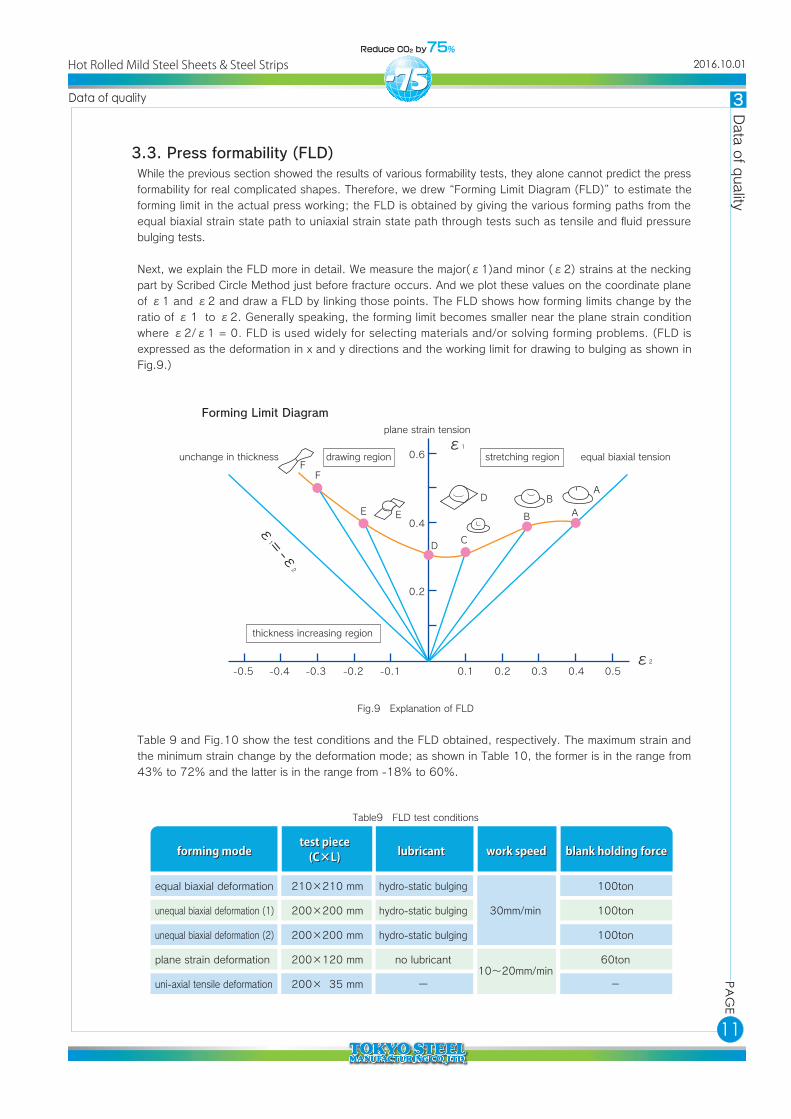
3.3. Press formability (FLD)While the previous section showed the results of various formability tests, they alone cannot predict the press formability for real complicated shapes. Therefore, we drew “Forming Limit Diagram (FLD)” to estimate the forming limit in the actual press working; the FLD is obtained by giving the various forming paths from the equal biaxial strain state path to uniaxial strain state path through tests such as tensile and fluid pressure bulging tests.
Next, we explain the FLD more in detail. We measure the major(ε1)and minor (ε2) strains at the necking part by Scribed Circle Method just before fracture occurs. And we plot these values on the coordinate plane of ε1 and ε2 and draw a FLD by linking those points. The FLD shows how forming limits change by the ratio of ε1 to ε2. Generally speaking, the forming limit becomes smaller near the plane strain condition where ε2/ε1 = 0. FLD is used widely for selecting materials and/or solving forming problems. (FLD is expressed as the deformation in x and y directions and the working limit for drawing to bulging as shown in Fig.9.)
Table 9 and Fig.10 show the test conditions and the FLD obtained, respectively. The maximum strain and the minimum strain change by the deformation mode; as shown in Table 10, the former is in the range from 43% to 72% and the latter is in the range from -18% to 60%.
forming modeforming modetest piece
(C×L)test piece
(C×L) lubricantlubricant work speedwork speed blank holding forceblank holding force
equal biaxial deformation
unequal biaxial deformation (1)
unequal biaxial deformation (2)
plane strain deformation
uni-axial tensile deformation
210×210 mm
200×200 mm
200×200 mm
200×120 mm
200× 35 mm
hydro-static bulging
hydro-static bulging
hydro-static bulging
no lubricant
ー
100ton
100ton
100ton
60ton
-
30mm/min
10~20mm/min
Table9 FLD test conditions
Fig.9 Explanation of FLD
Hot Rolled Mild Steel Sheets & Steel Strips 2016.10.01

12
PAG
EPA
GE
3 Data o
f quality
Data of quality
Deformation modeDeformation modeforming limitforming limit
Ex(%)Ex(%) Ey(%)Ey(%)
equal biaxial deformation
unequal biaxial deformation (1)
unequal biaxial deformation (2)
plane strain deformation
uni-axial tensile deformation
72
53
48
43
58
60
29
13
2
-18
Table10 Results of FLD test
Fig.10 Forming limit diagram
-50 -40 -30 -20 -10 0 10 20 30 40 50 60 70 80
80
70
60
50
40
30
20
10
90
Ey(%)
Ex(%)
○:Good(○…the maximum value)×:NG(×…the minimum value)●:Forming Limit Diagram
Hot Rolled Mild Steel Sheets & Steel Strips 2016.10.01

13
PAG
EPA
GE
3 Data o
f quality
Data of quality
tensile fatigue test plane bending fatigue test
3.4. Fatigue propertyWe carried out tensile fatigue test and plane bending fatigue test, of which test pieces are shown in Fig.11. Table11 shows the test conditions. Table12 and Fig.12 show the test results. The tensile fatigue limit and plane bending fatigue limit were 320 MPa and 170 MPa, respectively.
itemitem tensile fatigue testtensile fatigue test plane bending fatigue testplane bending fatigue test
stress ratio
test frequency
maximum number of cycles
0.05 -1.0
20Hz
1×10⁷ times
Table11 Fatigue test conditions
No.No. notenotetensile fatigue testtensile fatigue test
maximum stress(MPa)
maximum stress(MPa)
number of cycles(cycle)
number of cycles(cycle)
plane bending fatigue testplane bending fatigue test
maximum stress(MPa)
maximum stress(MPa)
number of cycles(cycle)
number of cycles(cycle)
1
2
3
4
5
6
7
8
9
10
200
240
300
320
330
340
350
370
380
390
no failure
no failure
no failure
no failure
failure
failure
failure
failure
failure
failure
notenote
no failure
failure
failure
failure
failure
failure
failure
failure
2,015,000
4,968,000
10,000,000
10,000,000
3,789,981
478,486
281,532
13,540
9,329
2,931
170
180
190
200
220
230
250
270
10,000,000
3,878,300
1,394,800
1,145,800
473,200
293,600
166,700
85,000
Table12 Results of fatigue test
Fig.11 Specimen of fotlgue test
Fig.12 S-N curves
450
400
350
300
250
200
150
300
250
200
150
1.0E+03 1.0E+04 1.0E+05 1.0E+06 1.0E+07 1.0E+04 1.0E+05 1.0E+06 1.0E+07
Hot Rolled Mild Steel Sheets & Steel Strips 2016.10.01

14
PAG
EPA
GE
3 Data o
f quality
Data of quality
3.5. Spot weldability3.5.1 Range of suitable welding currentThe current range, from the minimum current required to give a nugget diameter of 4√t( 5.06 mm in the present test) to the current resulting in the onset of expulsion was adopted as the suitable welding current range. We employed DR-shaped electrode of d=6 mm shown in Fig.13 and carried out spot welding on the basic conditions in Table13. Table14 lists each condition and its measured nugget diameter.It is concluded from Table14 and Fig.5 that the minimum limit current is 6.3 kA and the suitable current range is 2.5 kA (Table 15). Photo.5 shows typical cross sections of the welds.
markmark
ModelModelface diameterface diameter
D typeD type
rr RR ddDD rr
DR typeDR type
10
13
16
20
25
32
40
5
6.5
8
10
12.5
16
20
32
40
50
63
80
100
5
6
8
6.5
8
10
electrodeinitial pressure timeelectrode force welding timeholding timeflow rate of cooling water
electrodeinitial pressure timeelectrode force welding timeholding timeflow rate of cooling water
test piece №test piece № welding current (kA)welding current (kA) weld thickness (mm)weld thickness (mm) expulsionexpulsion nugget diameter (mm)nugget diameter (mm)
1%Cr-Cu dome type φ16mm tip (nose) φ6mm(R40)
29cycles/50Hz
270kg
15cycles/50Hz
1cycles/50Hz
top and bottom 2.5L/min.
1
2
3
4
5
6
7
8
9
10
11
12
13
14
15
4.6
4.9
5.2
5.5
5.8
6.1
6.4
6.7
7.0
7.3
7.6
7.9
8.2
8.5
8.8
3.11
3.10
3.11
3.11
3.09
3.08
3.07
3.07
3.04
3.01
3.00
3.00
2.94
2.92
2.82
none
none
none
none
none
none
none
none
none
none
none
none
none
none
expulsion
-
0.99
2.54
3.35
4.24
4.78
-
5.23
-
6.05
-
6.40
-
6.86
-
Fig.13 Electrode shape
Table13 Base conditions for spot welding
Table14 Conditions for spot welding and diameters of nugget
reference : JIS C 9304(1999)
D
R
d
r
Hot Rolled Mild Steel Sheets & Steel Strips 2016.10.01

15
PAG
EPA
GE
3 Data o
f quality
Data of quality
Photo5 Cross sections of welds (Enclosure line is appointed at suitable welding current range)
No.2(4.9kA) No.3(5.2kA)
No.4(5.5kA) No.5(5.8kA)
No.6(6.1kA) No.8(6.7kA)
No.10(7.3kA)
No.14(8.5kA)
No.12(7.9kA)
Hot Rolled Mild Steel Sheets & Steel Strips 2016.10.01
16
PAG
EPA
GE
3 Data o
f quality
Data of quality
10
9
8
7
6
5
4
3
2
1
04 5 6 7 8
welding current (kA)
nugg
et d
iam
eter
at cr
oss
sec
tion
(mm
)
9 10 11 12
4√t
expulsion8.8kA
6.3kA
(a) (b)
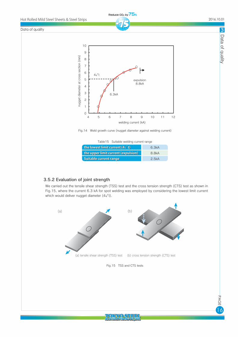
(a) tensile shear strength (TSS) test (b) cross tension strength (CTS) test
3.5.2 Evaluation of joint strengthWe carried out the tensile shear strength (TSS) test and the cross tension strength (CTS) test as shown in Fig.15, where the current 6.3 kA for spot welding was employed by considering the lowest limit current which would deliver nugget diameter (4√t).
the lowest limit current (4√t)the upper limit current (expulsion)Suitable current range
the lowest limit current (4√t)the upper limit current (expulsion)Suitable current range
6.3kA
8.8kA
2.5kA
Table15 Suitable welding current range
Fig.15 TSS and CTS tests
Fig.14 Weld growth curve (nugget diameter against welding current)
Hot Rolled Mild Steel Sheets & Steel Strips 2016.10.01

17
PAG
EPA
GE
3 Data o
f quality
Data of quality
d1
d2
d1
d2
d1
d2
d1d3
d2
symmetry plug fracture
asymmetry plug fracture
a) in case of plug fracture
b) in case of interfacial fracture
c) in case of partial plug fracture
shear-fractured nugget
corona-bond
Tables 16 and 17 show the performance of the weld joints and the average joint strengths, respectively. Both of TSS and CTS tests show that the fractured modes are of the mother metal plug. And both of the strengths are higher than those of conventional mild steel sheets, indicating sufficient joint strengths.
test typetest type test No.test No.
TSS (kN)
TSS (kN)
TSS (kN)
TSS (kN)
TSS (kN)
CTS (kN)
CTS (kN)
CTS (kN)
CTS (kN)
CTS (kN)
macro
macro
1
2
3
4
5
6
7
8
9
10
11
12
welding current (kA)
welding current (kA)6.3
6.3
6.3
6.3
6.3
6.3
6.3
6.3
6.3
6.3
6.3
6.3
weld thickness (mm)
weld thickness (mm)3.11
3.10
3.11
3.11
3.09
3.08
3.07
3.07
3.04
3.01
3.00
3.00
expulsionexpulsion
none
none
none
none
none
none
none
none
none
none
none
none
nugget diameter(mm)
nugget diameter(mm)
4.36
4.65
fracture modefracture mode
mother metal plug
mother metal plug
mother metal plug
mother metal plug
mother metal plug
mother metal plug
mother metal plug
mother metal plug
mother metal plug
mother metal plug
joint strength(kN)
joint strength(kN)
11.21
11.09
11.16
11.31
11.21
8.77
8.65
8.60
8.70
8.52
nugget diameter (mm)
nugget diameter (mm)
4.65 (3.7√t)
tensile shearing test (kN)
tensile shearing test (kN)
(σ=0.072)
cross tension test (kN)
cross tension test (kN)
(σ=0.085)11.20 8.65
Table16 Results of joint performance tests
Table17 Joint strength on average
Fig.16 Fracture pattern
reference : JIS Z 3136(1999)
Hot Rolled Mild Steel Sheets & Steel Strips 2016.10.01

edited 2016 October
HP http://www.tokyosteel.co.jp
Location Head office Kasumigaseki-Tokyu Bldg15F, 3-7-1, Kasumigaseki, Chiyoda-ku, Tokyo 100-0013, Japan Telephone(81)3-3501-3223 FAX.(81)3-3580-8859 (sales) Osaka branch office Osaka Kokusai Bldg, 3F, 2-3-13, Azuchi-cho, Chuo-ku, Osaka-shi, Osaka 541-0052, Japan Telephone(81)6-6264-1368 FAX.(81)6-6264-6396 Nagoya branch office Nittochi Nagoya Bldg, 7F, 2-1-1,Sakae, Naka-ku, Nagoya-shi, Aichi 460-0008, Japan Telephone(81)52-203-0855 FAX.(81)52-203-3021 Kyushu branch office 3-5-1, Minami Futajima, Wakamatsu-ku, Kitakyushu-shi, Fukuoka 808-0109, Japan (Located at Kyushu Plant) Telephone(81)93-791-5988 FAX.(81)93-701-3581 Okayama sales office 4-1-1, Minamise, Kurashiki-shi, Okayama 712-8055, Japan (Located at Okayama Plant) Telephone(81)86-455-7169 FAX.(81)86-455-3105 Utsunomiya sales office 11-1, Kiyohara-kogyo-danchi, Utsunomiya-shi, Tochigi 321-3231, Japan (Located at Utsunomiya Plant) Telephone(81)28-670-6235 FAX.(81)28-670-6238
Tahara Plant 2-1-3, Shirahama, Tahara-shi, Aichi 441-3436, Japan Telephone(81)531-24-0810 FAX.(81)531-24-0818 Okayama Plant 4-1-1, Minamise, Kurashiki-shi, Okayama 712-8055, Japan Telephone(81)86-455-7151 FAX.(81)86-455-3105 Kyushu Plant 3-5-1, Minami Futajima, Wakamatsu-ku, Kitakyushu-shi, Fukuoka 808-0109, Japan Telephone(81)93-791-2635 FAX.(81)93-791-2639 Utsunomiya Plant 11-1, Kiyohara-kogyo-danchi, Utsunomiya-shi, Tochigi 321-3231, Japan Telephone(81)28-670-5607 FAX.(81)28-670-5608 Takamatsu Steel Center 5-1-1, Asahi-machi, Takamatsu-shi, Kagawa 760-0065, Japan Telephone(81)87-822-3111 FAX.(81)87-822-3117
All copyrights are preserved and information described in this technical paper and on our products belong to Tokyo Steel Manufacturing Co., Ltd.


