RULES
PUBLICATION NO. 114/P
LONGITUDINAL STRENGTH STANDARD FOR CONTAINER SHIPS
2017 July
Publications P (Additional Rule Requirements) issued by Polski Rejestr Statków complete or extend the Rules and are mandatory where applicable
GDAŃSK

Publication No. 114 /P – Longitudinal Strength Standard for Container Ships – July 2017, based on the IACS Unified Requirements S11A, is an extension of the requirements contained in Part II – Hull of the Rules for the Classification and Construction of Sea-going Ships.
The Publication was approved by the PRS Board on 28 June 2017 and enters into force on 1 July 2017.
© Copyright by Polski Rejestr Statków S.A., 2017
PRS/OP, 06/2017

CONTENTS Page
1 General............................................................................................................................................................. 5 1.1 Application ............................................................................................................................................... 5 1.2 Symbols and definitions ............................................................................................................................ 5 1.3 Corrosion margin and net thickness........................................................................................................... 7
2 Loads ................................................................................................................................................................ 9 2.1 Sign convention for hull girder loads ....................................................................................................... 9 2.2 Still water bending moments and shear forces ......................................................................................... 9 2.3 Wave loads ............................................................................................................................................... 10 2.4 Load cases ................................................................................................................................................ 13 2.5 Hull girder stress....................................................................................................................................... 14
3 Strength Assessment ....................................................................................................................................... 14 3.1 General ..................................................................................................................................................... 14 3.2 Stiffners criterion...................................................................................................................................... 14 3.3 Yield strength assessment......................................................................................................................... 14
4 Buckling strength ............................................................................................................................................ 15 4.1 Application ............................................................................................................................................... 15 4.2 Buckling criteria ....................................................................................................................................... 15 4.3 Buckling utilisation factor ........................................................................................................................ 15 4.4 Stress determination ................................................................................................................................. 16
5 Hull girder ultimate strength ......................................................................................................................... 17 5.1 General ..................................................................................................................................................... 17 5.2 Hull girder ultimate bending moments ..................................................................................................... 17 5.3 Hull girder ultimate bending capacity ...................................................................................................... 18 5.4 Acceptance criteria ................................................................................................................................... 18
6 Additional requirements for large container ships ...................................................................................... 19 6.1 General ..................................................................................................................................................... 19 6.2 Yielding and buckling assessment............................................................................................................ 19 6.3 Whipping .................................................................................................................................................. 19
Annex 1 – Calculation of shear flow.................................................................................................................... 21
Annex 2 – Buckling capacity................................................................................................................................ 26
Annex 3 – Buckling capacity of overall stiffened panel ..................................................................................... 40

1 GENERAL
1.1 Application
1.1.1 Application
This Publication applies to the following types of steel ships with a length L of 90 m and greater and operated in unrestricted service 1. Container ships, 2. Ships dedicated primarily to carry their load in containers.
1.1.2 Load limitations
The wave induced load requirements apply to monohull displacement ships in unrestricted service and are limited to ships meeting the following criteria: (i) Length 90 m L 500 m (ii) Proportion 5 L/B 9; 2 B/T 6 (iii) Block coefficient at scantling draught 0.55 CB 0.9
For ships that do not meet all of the aforementioned criteria, special considerations such as direct calculations of wave induced loads may be required by PRS.
1.1.3 Longitudinal extent of strength assessment
The stiffness, yield strength, buckling strength and hull girder ultimate strength assessment are to be carried out in way of 0.2L to 0.75L with due consideration given to locations where there are significant changes in hull cross section, e.g. changing of framing system and the fore and aft end of the forward bridge block in case of two-island designs.
In addition, strength assessments are to be carried out outside this area. As a minimum assessments are to be carried out at forward end of the foremost cargo hold and the aft end of the aft most cargo hold. Evaluation criteria used for these assessments are determined in PRS Rules for the Classification and Construction of Sea-going Ships Part II – Hull.
1.2 Symbols and definitions
1.2.1 Symbols
L – rule length, in m, as defined in IACS UR S2; B – moulded breadth, in [m]; C – wave parameter, see 2.3.1; T – scantling draught in m CB – block coefficient at scantling draught; CW – waterplane coefficient at scantling draught, to be taken as:
LB
AC W
W ;
AW – waterplane area at scantling draught, in [m2]; ReH – specified minimum yield stress of the material, in [N/mm2]; k – Material factor as defined in IACS UR S4 for higher tensile steels, k =1.0 for mild steel
having a minimum yield strength equal to 235 N/mm2; E – Young's modulus in [N/mm2] to be taken as E = 2.06·105 N/mm2 for steel; MS – vertical still water bending moment in seagoing condition, in [kNm], at the cross section
under consideration; MSmax, MSmin – permissible maximum and minimum vertical still water bending moments in seagoing
condition, in [kNm], at the cross section under consideration, see 2.2.2; MW – vertical wave induced bending moment, in [kNm], at the cross section under
consideration;
5

FS – vertical still water shear force in seagoing condition, in [kN], at the cross section under consideration;
FSmax, FSmin – permissible maximum and minimum still water vertical shear force in seagoing condition, in [kN], at the cross section under consideration, see 2.2.2;
FW – vertical wave induced shear force, in [kN], at the cross section under consideration; qv – shear flow along the cross section under consideration, to be determined according to
Annex 1; fNL-Hog – non-linear correction factor for hogging, see 2.3.2; fNL-Sag – non-linear correction factor for sagging, see 2.3.2; fR – factor related to the operational profile, see 2.3.2; tnet – net thickness, in mm, see 1.3.1; tres – reserve thickness, to be taken as 0.5mm; Inet – net vertical hull girder moment of inertia at the cross section under consideration, to be
determined using net scantlings as defined in 1.3, in [m4]; HG – hull girder bending stress, in [N/mm2], as defined in 2.5; HG – hull girder shear stress, in [N/mm2], as defined in 2.5; x – longitudinal co-ordinate of a location under consideration, in [m]; Z – vertical co-ordinate of a location under consideration, in [m]; Zn – distance from the baseline to the horizontal neutral axis, in [m].
1.2.2 Fore end and aft end
The fore end (FE) of the rule length L, see Figure 1.2.2, is the perpendicular to the scantling draught waterline at the forward side of the stem.
The aft end (AE) of the rule length L, see Figure 1.2.2, is the perpendicular to the scantling draught waterline at a distance L aft of the fore end (FE).
Fig. 1.2.2 Ends of length L
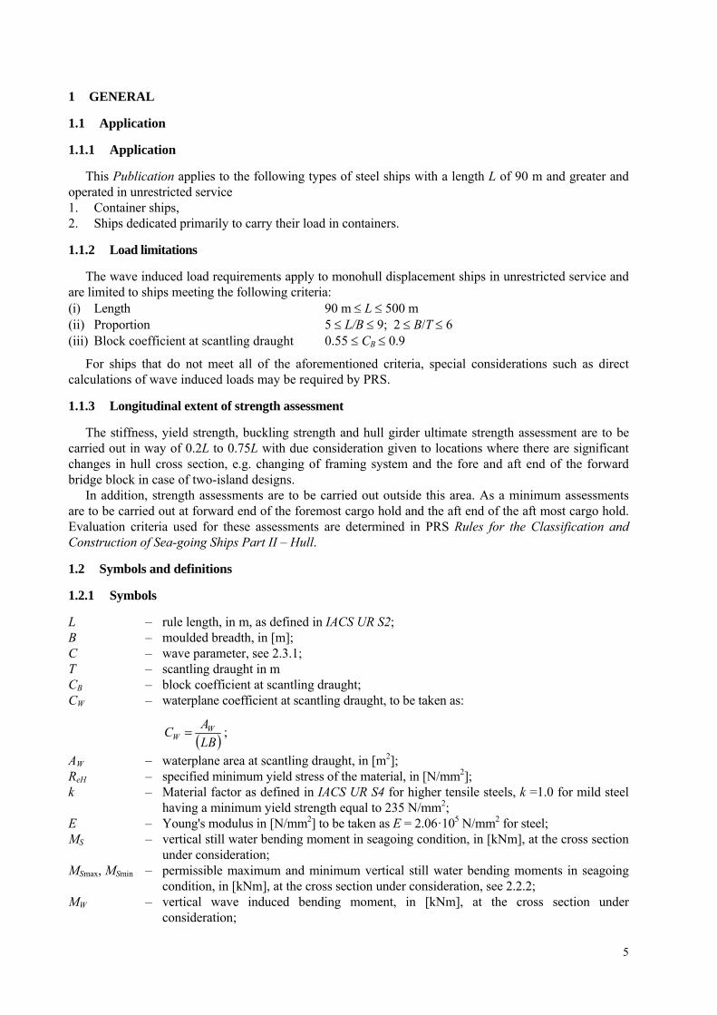
1.2.3 Reference coordinate system
The ships geometry, loads and load effects are defined with respect to the following right-hand coordinate system (see Figure 1.2.3):
Origin: At the intersection of the longitudinal plane of symmetry of ship, the aft end of L and the baseline.
X axis: Longitudinal axis, positive forwards. Y axis: Transverse axis, positive towards portside Z axis: Vertical axis, positive upwards.
6
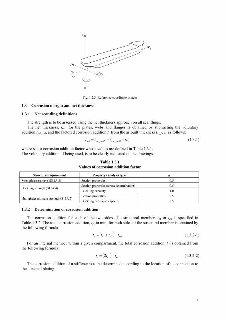
Fig. 1.2.3 Reference coordinate system
1.3 Corrosion margin and net thickness
1.3.1 Net scantling definitions
The strength is to be assessed using the net thickness approach on all scantlings. The net thickness, tnet, for the plates, webs and flanges is obtained by subtracting the voluntary
addition tvol_add and the factored corrosion addition tc from the as built thickness tas_built, as follows:
caddvolbuiltasnet tttt __ (1.3.1)
where is a corrosion addition factor whose values are defined in Table 1.3.1. The voluntary addition, if being used, is to be clearly indicated on the drawings.
Table 1.3.1 Values of corrosion addition factor
Structural requirement Property / analysis type
Strength assessment (S11A.3) Section properties 0.5
Section properties (stress determination) 0.5 Buckling strength (S11A.4)
Buckling capacity 1.0
Section properties 0.5 Hull girder ultimate strength (S11A.5)
Buckling / collapse capacity 0.5
1.3.2 Determination of corrosion addition
The corrosion addition for each of the two sides of a structural member, tc1 or tc2 is specified in Table 1.3.2. The total corrosion addition, tc, in mm, for both sides of the structural member is obtained by the following formula:
resccc tttt 21 (1.3.2-1)
For an internal member within a given compartment, the total corrosion addition, tc is obtained from the following formula:
rescc ttt 12 (1.3.2-2)
The corrosion addition of a stiffener is to be determined according to the location of its connection to the attached plating
7
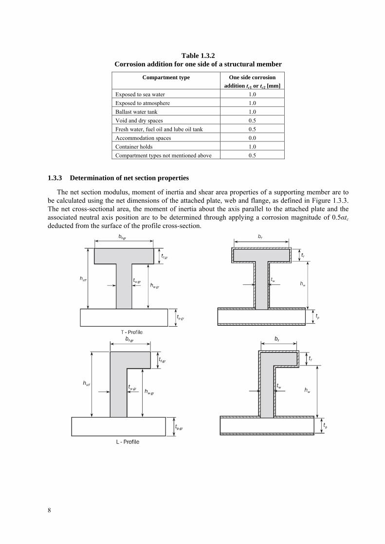
Table 1.3.2 Corrosion addition for one side of a structural member
Compartment type One side corrosion
addition tc1 or tc2 [mm]
Exposed to sea water 1.0
Exposed to atmosphere 1.0
Ballast water tank 1.0
Void and dry spaces 0.5
Fresh water, fuel oil and lube oil tank 0.5
Accommodation spaces 0.0
Container holds 1.0
Compartment types not mentioned above 0.5
1.3.3 Determination of net section properties
The net section modulus, moment of inertia and shear area properties of a supporting member are to be calculated using the net dimensions of the attached plate, web and flange, as defined in Figure 1.3.3. The net cross-sectional area, the moment of inertia about the axis parallel to the attached plate and the associated neutral axis position are to be determined through applying a corrosion magnitude of 0.5αtc deducted from the surface of the profile cross-section.
8

Fig. 1.3.3 Net sectional properties of supporting members
2 LOADS
2.1 Sign convention for hull girder loads
The sign conventions of vertical bending moments and vertical shear forces at any ship transverse section are as shown in Figure 2.1, namely: the vertical bending moments MS and MW are positive when they induce tensile stresses in the strength
deck (hogging bending moment) and negative when they induce tensile stresses in the bottom (sagging bending moment);
the vertical shear forces FS, FW are positive in the case of downward resulting forces acting aft of the transverse section and upward resulting forces acting forward of the transverse section under consideration. The shear forces in the directions opposite to above are negative.
Bending moments:
Shear forces:
Fig. 2.1 Sign conventions of bending moments and shear forces
2.2 Still water bending moments and shear forces
2.2.1 General
Still water bending moments, MS in [kNm], and still water shear forces, FS in [kN], are to be calculated at each section along the ship length for design loading conditions as specified in 2.2.2.
9

2.2.2 Design loading conditions
In general, the design cargo and ballast loading conditions, based on amount of bunker, fresh water and stores at departure and arrival, are to be considered for the MS and FS calculations. Where the amount and disposition of consumables at any intermediate stage of the voyage are considered more severe, calculations for such intermediate conditions are to be submitted in addition to those for departure and arrival conditions. Also, where any ballasting and/or de-ballasting is intended during voyage, calculations of the intermediate condition just before and just after ballasting and/or de-ballasting any ballast tank are to be submitted and where approved included in the loading manual for guidance.
The permissible vertical still water bending moments MSmax and MSmin and the permissible vertical still water shear forces FSmax and FSmin in seagoing conditions at any longitudinal position are to envelop: the maximum and minimum still water bending moments and shear forces for the seagoing loading
conditions defined in the Loading Manual; the maximum and minimum still water bending moments and shear forces specified by the designer.
The Loading Manual should include the relevant loading conditions, which envelop the still water hull girder loads for seagoing conditions, including those specified in Publication No. 16/P.
2.3 Wave loads
2.3.1 Wave parameter
The wave parameter is defined as follows
22
15011
.
refL
L.C
for L Lref (2.3.1-1)
71
14501
.
refL
L.C
for L > Lref (2.3.1-2)
where: Lref – reference length, in [m], taken as:
3.1315 Wref CL for the determination of vertical wave bending moments according to 2.3.2 3.1330 Wref CL for the determination of vertical wave shear forces according to 2.3.3.
2.3.2 Vertical wave bending moments
The distribution of the vertical wave induced bending moments, MW in [kNm], along the ship length is given in Figure 2.3.2-2, where:
HogNLWRHogW fL
BCCLfM
8.035.1 (2.3.2-1)
SagNLWRSagW fL
BCCLfM
8.035.1 (2.3.2-2)
where: fR – factor related to the operational profile, to be taken as:
fR = 0.85; fNL-Hog – non-linear correction for hogging, to be taken as:
TC
Cf
W
BHogNL 3.0 , not to be taken greater than 1.1;
fNL-Sag – non-linear correction for sagging, to be taken as:
10

3.0
2.015.4
LCC
fF
BW
BowSagNL
, not to be taken less than 1.0;
fBow – bow flare shape coefficient, to be taken as:
f
WLDKBow Lz
AAf
2.0
;
ADK – projected area in horizontal plane of uppermost deck, in [m2] including the forecastle deck, if any, extending from 0.8L forward (see Figure 2.3.2-1). Any other structures, e.g. plated bulwark, are to be excluded;
AWL – waterplane area, in [m2], at draught T, extending from 0.8L forward; zf – vertical distance, in m, from the waterline at draught T to the uppermost deck (or forecastle
deck), measured at FE (see Figure 2.3.2-1). Any other structures, e.g. plated bulwark, are to be excluded.
Fig. 2.3.2-1 Projected area ADK and vertical distance zf
11

Fig. 2.3.2-2
2.3.3 Vertical wave shear force
The distribution of the vertical wave induced shear forces, FW in [kN], along the ship length is given in Figure 2.3.3, where:
HogNLWRAftHogW f
L
BCCLfF
7.03.02.5
8.02 (2.3.3-1)
HogNLWRForeHogW f
L
BCCLfF
8.027.5 (2.3.3-2)
SagNLWRAftSagW f
L
BCCLfF
7.03.02.5
8.02 (2.3.3-3)
SagNLWRForeSagW f
L
BCCLfF
75.025.07.5
8.02 (2.3.3-4)
8.0
20.4
L
BCCLfF WR
MidW (2.3.3-5)
12

Fig. 2.3.3 Distribution of vertical wave shear force FW along the ship length
2.4 Load cases
For the strength assessment, the maximum hogging and sagging load cases given in Table 2.4 are to be checked. For each load case the still water condition at each section as defined in 2.2 is to be combined with the wave condition as defined in 2.3, refer also to Figure 2.4.
Table 2.4 Combination of still water and wave bending moments and shear forces
Bending moment Shear force Load case
MS MW FS FW
FSmax for x 0.5L FWmax for x 0.5L Hogging MSmax MWH
FSmin for x > 0.5L FWmin for x > 0.5L
FSmin for x 0.5L FWmin for x 0.5L Sagging MSmin MWS
FSmax for x > 0.5L FWmax for x > 0.5L
MWH: wave bending moment in hogging at the cross section under consideration, to be taken as the positive
value of MW as defined in Figure 2.3.2-2;
MWS: wave bending moment in sagging at the cross section under consideration, to be taken as the negative
value of MW as defined Figure 2.3.2-2;
FWmax: Maximum value of the wave shear force at the cross section under consideration, to be taken as the
positive value of FW as defined Figure 2.3.3;
FWmin: minimum value of the wave shear force at the cross section under consideration, to be taken as the
negative value of FW as defined Figure 2.3.3.
13

Fig. 2.4 Load combination to determine the maximum hogging and sagging load cases as given in Table 2.4
2.5 Hull girder stress
The hull girder stresses in [N/mm2] are to be determined at the load calculation point under consideration, for the "hogging" and "sagging" load cases defined in 2.4 as follows:
Bending stress:
310
nnet
WWSSHG ZZ
I
MM (2.5-1)
Shear stress:
vnet
WWSSHG qt
FF
/
(2.5-2)
where: S, W: partial safety factors, to be taken as:
S = 1.0 W = 1.0
3 STRENGTH ASSESSMENT
3.1 General
Continuity of structure is to be maintained throughout the length of the ship. Where significant changes in structural arrangement occur adequate transitional structure is to be provided.
3.2 Stiffners criterion
The two load cases "hogging" and "sagging" as listed in 2.4 are to be checked. The net moment of inertia, in [m4], is not to be less than:
71055.1 WSnet MMI (3.2)
3.3 Yield strength assessment
3.3.1 General acceptance criteria
The yield strength assessment is to check, for each of the load cases "hogging" and "sagging" as defined in 2.4, that the equivalent hull girder stress σeq, in [N/mm2], is less than the permissible stress σperm, in [N/mm2], as follows:
14
σeq < σperm
where: 22 3 xeq
21 eH
permR
1: partial safety factor for material, to be taken as 2351
eHRk
2: partial safety factor for load combinations and permissible stress, to be taken as: 2 = 1.24, for bending strength assessment according to 3.3.2, 2 = 1.13, for shear stress assessment according to 3.3.3.
3.3.2 Bending strength assessment
The assessment of the bending stresses is to be carried out according to 3.3.1 at the following locations of the cross section at bottom, at deck, at top of hatch coaming, at any point where there is a change of steel yield strength. The following combination of hull girder stress as defined in 2.5 is to be considered:
= HG
= 0
3.3.3 Shear strength assessment
The assessment of shear stress is to be carried out according to 3.3.1 for all structural elements that contribute to the shear strength capability. The following combination of hull girder stress as defined in 2.5 is to be considered:
x = 0
4 BUCKLING STRENGTH
4.1 Application
These requirements apply to plate panels and longitudinal stiffeners subject to hull girder bending and shear stresses. Definitions of symbols used in the present Chapter 4 are given in Annex 2 "Buckling Capacity".
4.2 Buckling criteria
The acceptance criterion for the buckling assessment is defined as follows:
act 1
where: act – : maximum utilisation factor as defined in 4.3.
4.3 Buckling utilisation factor
The utilisation factor, ηact, is defined as the inverse of the stress multiplication factor at failure γc, see Figure 4.3.
cact
1
Failure limit states are defined in: Annex 2, 2 for elementary plate panels,
15
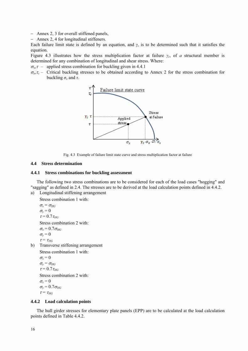
Annex 2, 3 for overall stiffened panels, Annex 2, 4 for longitudinal stiffeners. Each failure limit state is defined by an equation, and γc is to be determined such that it satisfies the equation. Figure 4.3 illustrates how the stress multiplication factor at failure γc, of a structural member is determined for any combination of longitudinal and shear stress. Where: x, – applied stress combination for buckling given in 4.4.1 x,c – Critical buckling stresses to be obtained according to Annex 2 for the stress combination for
buckling σx and τ.
Fig. 4.3 Example of failure limit state curve and stress multiplication factor at failure
4.4 Stress determination
4.4.1 Stress combinations for buckling assessment
The following two stress combinations are to be considered for each of the load cases "hogging" and "sagging" as defined in 2.4. The stresses are to be derived at the load calculation points defined in 4.4.2. a) Longitudinal stiffening arrangement
Stress combination 1 with: x = HG y = 0 = 0.7HG
Stress combination 2 with: x = 0.7HG y = 0 = HG
b) Transverse stiffening arrangement
Stress combination 1 with: x = 0 y = HG = 0.7HG
Stress combination 2 with: x = 0 y = 0.7HG = HG
4.4.2 Load calculation points
The hull girder stresses for elementary plate panels (EPP) are to be calculated at the load calculation points defined in Table 4.4.2.
16

Table 4.4.2 Load calculation points (LCP) coordinates for plate buckling assessment
Hull girder bending stress Hull girder shear stress LCP
coordinates Non horizontal plating Horizontal plating
x coordinate Mid-length of the EPP
y coordinate
Both upper and lower ends of
the EPP (points A1 and A2 in
Figure 4.4.2)
Outboard and inboard ends of
the EPP (points A1 and A2 in
Figure 4.4.2)
Mid-point of EPP (point B
in Figure 4.4.2)
z coordinate Corresponding to x and y values
Fig. 4.4.2 LCP for plate buckling - assessment, PSM stands for primary supporting members
The hull girder stresses for longitudinal stiffeners are to be calculated at the following load calculation point at the mid length of the considered stiffener; at the intersection point between the stiffener and its attached plate.
5 HULL GIRDER ULTIMATE STRENGTH
5.1 General
The hull girder ultimate strength is to be assessed for ships with length L equal or greater than 150m. The acceptance criteria, given in 5.4 are applicable to intact ship structures.
The hull girder ultimate bending capacity is to be checked for the load cases "hogging" and "sagging" as defined in 2.4.
5.2 Hull girder ultimate bending moments
The vertical hull girder bending moment, M in hogging and sagging conditions, to be considered in the ultimate strength check is to be taken as:
WWSS MMM (5.2)
where: MS – permissible still water bending moment, in [kNm], defined in 2.4; MW – vertical wave bending moment, in [kNm], defined in 2.4; S – partial safety factor for the still water bending moment, to be taken as:
S = 1.0 S – partial safety factor for the vertical wave bending moment, to be taken as:
W = 1.2.
17

5.3 Hull girder ultimate bending capacity
5.3.1 General
The hull girder ultimate bending moment capacity, MU is defined as the maximum bending moment capacity of the hull girder beyond which the hull structure collapses.
5.3.2 Determination of hull girder ultimate bending moment capacity
The ultimate bending moment capacities of a hull girder transverse section, in hogging and sagging conditions, are defined as the maximum values of the curve of bending moment M versus the curvature χ of the transverse section considered (MUH for hogging condition and MUS for sagging condition, see Figure 5.3.2). The curvature χ is positive for hogging condition and negative for sagging condition.
Fig. 5.3.2 Bending moment M versus curvature χ
The hull girder ultimate bending moment capacity MU is to be calculated using the incremental-iterative method as given in 2 of Annex 3 or using an alternative method as indicated in 3 of Annex 3
5.4 Acceptance criteria
The hull girder ultimate bending capacity at any hull transverse section is to satisfy the following criteria:
DBM
UMM
(5.4)
where: M – vertical bending moment, in [kNm], to be obtained as specified in 5.2; MU – hull girder ultimate bending moment capacity, in [kNm], to be obtained as specified in 5.3; M – partial safety factor for the hull girder ultimate bending capacity, covering material, geometric
and strength prediction uncertainties, to be taken as: M = 1.05;
DB – partial safety factor for the hull girder ultimate bending moment capacity, covering the effect of double bottom bending, to be taken as: for hogging condition γDB = 1.15; for sagging condition: γDB = 1.0.
For cross sections where the double bottom breadth of the inner bottom is less than that at amidships or where the double bottom structure differs from that at amidships (e.g. engine room sections), the factor γDB for hogging condition may be reduced based upon agreement with the PRS.
18
19
6 ADDITIONAL REQUIREMENTS FOR LARGE CONTAINER SHIPS
6.1 General
The requirements in 6.2 and 6.3 are applicable, in addition to requirements in Chapter 3 to 5, to container ships with a breadth B greater than 32.26 m.
6.2 Yielding and buckling assessment
Yielding and buckling assessments are to be carried out taking into consideration additional hull girder loads (wave torsion, wave horizontal bending and static cargo torque), as well as local loads as determined in PRS Publication No. 24/P – Strength Analysis of Container Ship Hull Structure and PRS Rules for the Classification and Construction of Sea-going Ships Part II – Hull – 18.4, 18.5. All in-plane stress components (i.e. bi-axial and shear stresses) induced by hull girder loads and local loads are to be considered.
6.3 Whipping
Hull girder ultimate strength is to take into consideration the whipping contribution to the vertical bending moment. Whipping contribution to the vertical bending moment will be determined by means of numerical analysis carried out with the use of dedicated computer program approved by PRS.
Entry information such as: critical loading conditions, forward speed and operational headings should be determined and agreed with PRS. North Atlantic wave scatter diagram should be employed for strength and fatigue assessment.
The computer program should consist of the following parts: – a fluid solver for the solution of the seakeeping problem; – a slamming solver for calculating slamming forces; – a structural solver for the elastic response of the hull (either a 1-D beam model or 3-D FE model
can be used). The program should be validated by means of experimental measurements in the Model Basin.

ANNEX 1 – CALCULATION OF SHEAR FLOW
1 General............................................................................................................................................................. 21
2 Determinate shear flow................................................................................................................................... 21
3 Indeterminate shear flow................................................................................................................................ 22
4 Computation of sectional properties ............................................................................................................. 23
1 GENERAL
This annex describes the procedures of direct calculation of shear flow around a ship's cross section due to hull girder vertical shear force. The shear flow qv at each location in the cross section, is calculated by considering the cross section is subjected to a unit vertical shear force of 1 N. The unit shear flow per mm, qv, in [N/mm], is to be taken as:
qv = qD + qI
where qD – determinate shear flow, as defined in 2; qI – indeterminate shear flow which circulates around the closed cells, as defined in 3.
In the calculation of the unit shear flow, qv, the longitudinal stiffeners are to be taken into account.
2 DETERMINATE SHEAR FLOW
The determinate shear flow, qD, in [N/mm] at each location in the cross section is to be obtained from the following line integration:
s
snetnnety
d dtzzI
sq0
610
1 (2-1)
where: s – coordinate value of running coordinate along the cross section, in [m]; Iy-nrt – net moment of inertia of the cross section, in [m4]; tnet – net thickness of plating, in [mm]; zn – Z coordinate of horizontal neutral axis from baseline, in [m].
It is assumed that the cross section is composed of line segments as shown in Figure 2-1: where each line segment has a constant plate net thickness. The determinate shear flow is obtained by the following equation.
DiniknetY
netDk qzzz
I
ltq
2102 6 (2-2)
where: qDk, qDi – determinate shear flow at node k and node i respectively , in [N/mm]; l – length of line segments, in [m]; yk, yi – Y coordinate of the end points k and i of line segment, in m, as defined in Figure 2-1; zk, zi – Z coordinate of the end points k and i of line segment, in m, as defined in Figure 2-1.
Where the cross section includes closed cells, the closed cells are to be cut with virtual slits, as shown in Figure 2-2: in order to obtain the determinate shear flow. These virtual slits must not be located in walls which form part of another closed cell. Determinate shear flow at bifurcation points is to be calculated by water flow calculations, or similar, as shown in Figure 2-2.
21
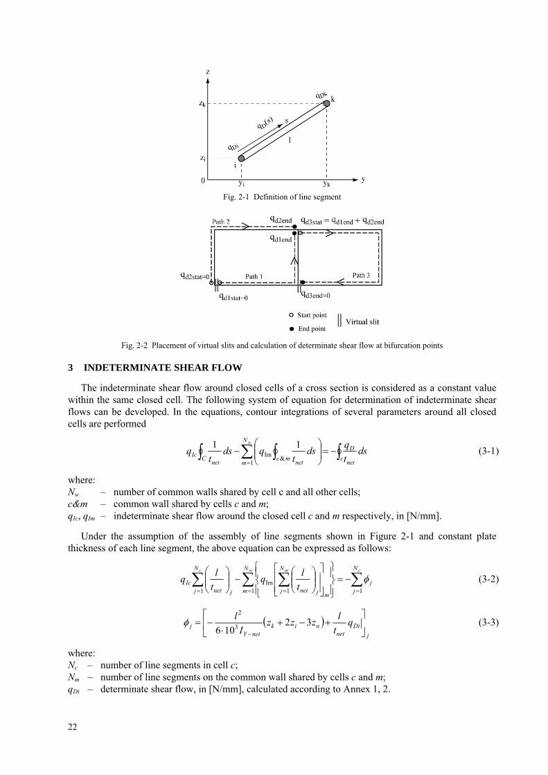
Fig. 2-1 Definition of line segment
Fig. 2-2 Placement of virtual slits and calculation of determinate shear flow at bifurcation points
3 INDETERMINATE SHEAR FLOW
The indeterminate shear flow around closed cells of a cross section is considered as a constant value within the same closed cell. The following system of equation for determination of indeterminate shear flows can be developed. In the equations, contour integrations of several parameters around all closed cells are performed
c
net
DN
mmc
netC
netIc ds
t
qds
tqds
tq
w
1&
Im11
(3-1)
where: Nw – number of common walls shared by cell c and all other cells; c&m – common wall shared by cells c and m; qIc, qIm – indeterminate shear flow around the closed cell c and m respectively, in [N/mm].
Under the assumption of the assembly of line segments shown in Figure 2-1 and constant plate thickness of each line segment, the above equation can be expressed as follows:
cw mc N
jj
N
mm
N
j jnet
N
j jnetIc t
lq
t
lq
11 1Im
1
(3-2)
j
Dinet
niknetY
j qt
lzzz
I
l
32106 3
2
(3-3)
where: Nc – number of line segments in cell c; Nm – number of line segments on the common wall shared by cells c and m; qDi – determinate shear flow, in [N/mm], calculated according to Annex 1, 2.
22
23
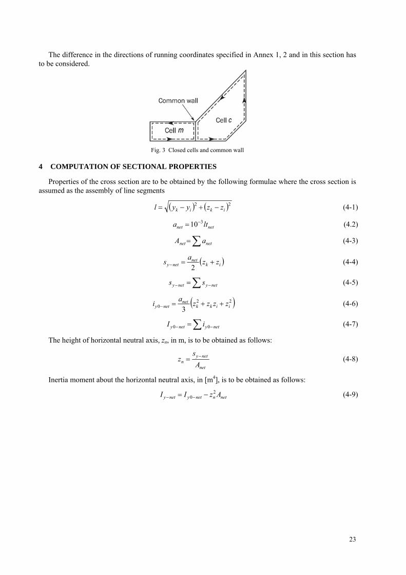
The difference in the directions of running coordinates specified in Annex 1, 2 and in this section has to be considered.
Fig. 3 Closed cells and common wall
4 COMPUTATION OF SECTIONAL PROPERTIES
Properties of the cross section are to be obtained by the following formulae where the cross section is assumed as the assembly of line segments
22ikik zzyyl (4-1)
(4.2) netnet lta 310
netnet aA (4-3)
iknet
nety zza
s 2 (4-4)
netynety ss (4-5)
220 3 iikk
netnety zzzz
ai (4-6)
netynety iI 00 (4-7)
The height of horizontal neutral axis, zn, in m, is to be obtained as follows:
net
netyn A
sz (4-8)
Inertia moment about the horizontal neutral axis, in [m4], is to be obtained as follows:
(4-9) netnnetynety AzII 20


ANNEX 2 – BUCKLING CAPACITY
1 Elementary Plate Panel (EPP) ....................................................................................................................... 26 1.1 Definition.................................................................................................................................................. 26 1.2 EPP with different thicknesses ................................................................................................................. 26
2 Buckling capacity of plates ............................................................................................................................. 27 2.1 Plate panel ................................................................................................................................................ 27 2.2 Curved plate panels .................................................................................................................................. 32
3 Buckling capacity of overall stiffened panel ................................................................................................. 33
4 Buckling capacity of longitudinal stiffeners.................................................................................................. 33 4.1 Stiffeners limit states ................................................................................................................................ 33 4.2 Lateral pressure ........................................................................................................................................ 33 4.3 Stiffener idealization................................................................................................................................. 34 4.4 Ultimate buckling capacity ....................................................................................................................... 36
Symbols:
x axis – local axis of a rectangular buckling panel parallel to its long edge; y axis – local axis of a rectangular buckling panel perpendicular to its long edge; x – membrane stress applied in x direction, in [N/mm2]; y – membrane stress applied in y direction, in [N/mm2]; c – membrane shear stress applied in xy plane, in [N/mm2]; a – axial stress in the stiffener, in [N/mm2] b – bending stress in the stiffener, in [N/mm2]; w – warping stress in the stiffener, in [N/mm2]; cx, cy, c – critical stress, in [N/mm2], defined in 2.1.1 for plates; ReH_S – specified minimum yield stress of the stiffener, in [N/mm2]; ReH_P – specified minimum yield stress of the plate, in [N/mm2]; a – length of the longer side of the plate panel as shown in Table 2.1.4-2, in [mm]; b – length of the shorter side of the plate panel as shown in Table 2.1.4-2, in [mm]; d – length of the side parallel to the axis of the cylinder corresponding to the curved plate
panel as shown in Table 2.2, in [mm]; E – elastic buckling reference stress, in [N/mm2] to be taken as:
for the application of plate limit state according to 2.1.2
2
2
2
112
b
t
v
E pE
for the application of curved plate panels according to 2.2:
2
2
2
112
d
t
v
E pE
v – Poisson's ratio to be taken equal to 0.3; tp – net thickness of plate panel, in [mm]; tw – net stiffener web thickness, in [mm]; tf – net flange thickness, in [mm]; bf – breadth of the stiffener flange, in [mm]; hw – stiffener web height, in [mm]; ef – distance from attached plating to centre of flange, in [mm], to be taken as:
ef = hw for flat bar profile; ef = hw – 0.5 tf for bulb profile; ef = hw + 0.5 tf for angle and Tee profiles;
25
– aspect ratio of the plate panel, to be taken as b
a ;
– coefficient taken as
1
;
– edge stress ratio to be taken as 1
2
;
1 – maximum stress, in [N/mm2]; 2 – minimum stress, in [N/mm2]; R – radius of curved plate panel, in [mm]; l – span, in mm, of stiffener equal to the spacing between primary supporting members; s – spacing of stiffener, in mm, to be taken as the mean spacing between the stiffeners of the
considered stiffened panel
1 ELEMENTARY PLATE PANEL (EPP)
1.1 Definition
An Elementary Plate Panel (EPP) is the unstiffened part of the plating between stiffeners and/or primary supporting members.
All the edges of the elementary plate panel are forced to remain straight (but free to move in the in-plane directions) due to the surrounding structure/neighbouring plates (usually longitudinal stiffened panels in deck, bottom and inner-bottom plating, shell and longitudinal bulkheads).
1.2 EPP with different thicknesses
1.2.1 Longitudinally stiffened EPP with different thicknesses
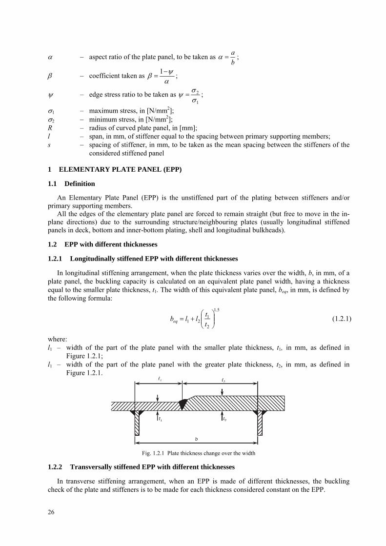
In longitudinal stiffening arrangement, when the plate thickness varies over the width, b, in mm, of a plate panel, the buckling capacity is calculated on an equivalent plate panel width, having a thickness equal to the smaller plate thickness, t1. The width of this equivalent plate panel, beq, in mm, is defined by the following formula:
5.1
2
121
t
tllbeq (1.2.1)
where: l1 – width of the part of the plate panel with the smaller plate thickness, t1, in mm, as defined in
Figure 1.2.1; l1 – width of the part of the plate panel with the greater plate thickness, t2, in mm, as defined in
Figure 1.2.1.
Fig. 1.2.1 Plate thickness change over the width
1.2.2 Transversally stiffened EPP with different thicknesses
In transverse stiffening arrangement, when an EPP is made of different thicknesses, the buckling check of the plate and stiffeners is to be made for each thickness considered constant on the EPP.
26

2 BUCKLING CAPACITY OF PLATES
2.1 Plate panel
2.1.1 Plate limit state
The plate limit state is based on the following interaction formulae: a) longitudinal stiffening arrangement:
1
25.025.0 /2/2
pp
c
c
cx
xc
(2.1.1-1)
b) Transverse stiffening arrangement
1
25.025.0/2/2
pp
c
c
cy
yc
(2.1.1-2)
where: x, y – applied normal stress to the plate panel in [N/mm2], as defined in 4.4, at load calculation points
of the considered elementary plate panel; – applied shear stress to the plate panel, in [N/mm2], as defined in 4.4, at load calculation points
of the considered elementary plate panel; cx – ultimate buckling stress in [N/mm2] in direction parallel to the longer edge of the buckling
panel as defined in 2.1.3; cy – ultimate buckling stress in [N/mm2] in direction parallel to the shorter edge of the buckling
panel as defined in 2.1.3; c – ultimate buckling shear stress, in [N/mm2] as defined in 2.1.3; p – plate slenderness parameter taken as:
E
R
t
b PeH
pp
_ .
2.1.2 Reference degree of slenderness
The reference degree of slenderness is to be taken as:
E
PeH
K
R
_ (2.1.2)
where: K – buckling factor, as defined in Table 2.1.4-2 and Table 2.2.
2.1.3 Ultimate buckling stresses
The ultimate buckling stress of plate panels, in [N/mm2], is to be taken as:
PeHxcx RC _ (2.1.3-1)
PeHycy RC _ (2.1.3-2)
The ultimate buckling stress of plate panels subject to shear, in [N/mm2], is to be taken as:
3_ PeH
c
RC (2.1.3-3)
where: Cx, Cy, C – reduction factors, as defined in Table 2.1.4-2.
27
The boundary conditions for plates are to be considered as simply supported (see cases 1, 2 and 15 of Table 2.1.4-2). If the boundary conditions differ significantly from simple support, a more appropriate boundary condition can be applied according to the different cases of Table 2.1.4-2 subject to the agreement of PRS.
2.1.4 Correction Factor Flong
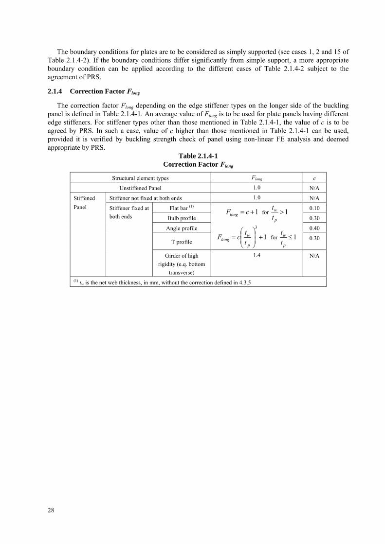
The correction factor Flong depending on the edge stiffener types on the longer side of the buckling panel is defined in Table 2.1.4-1. An average value of Flong is to be used for plate panels having different edge stiffeners. For stiffener types other than those mentioned in Table 2.1.4-1, the value of c is to be agreed by PRS. In such a case, value of c higher than those mentioned in Table 2.1.4-1 can be used, provided it is verified by buckling strength check of panel using non-linear FE analysis and deemed appropriate by PRS.
Table 2.1.4-1 Correction Factor Flong
Structural element types Flong c
Unstiffened Panel 1.0 N/A
Stiffener not fixed at both ends 1.0 N/A
Flat bar (1) 0.10
Bulb profile 0.30
Angle profile 0.40
T profile
1 cFlong for 1p
w
t
t
1
3
p
wlong t
tcF for 1
p
w
t
t 0.30
Stiffened
Panel Stiffener fixed at
both ends
Girder of high
rigidity (e.q. bottom
transverse)
1.4 N/A
(1) tw is the net web thickness, in mm, without the correction defined in 4.3.5
28

Table 2.1.4-2 Buckling factor and reduction factor for plane plate panels
Case Stress
ratio
Aspect
ratio
Buckling factor K Reduction factor C
1
0
1.1
4.8
longx FK
0 >
>
–1
1026.663.7 longx FK
1
–1
21975.5 longx FK
Cx = 1 for c
2
22.01
cCx for > c
where:
25.112.025.1 c
c
cc
88.011
2
12
2
2
9.6
4.2
100
11
112
f
K y
6 111 f
1
0
> 6
146
16.01f
but not greater than 2
35.05.14
21
23
22
239.64.21001
1200
fffK y
>
6(1
–
)
14
16.01f
but not greater than 14.5 – 0.35 2
f2 = f3 = 0
3(1
–
)
6(1
–
) 11
1
f
f2 = f3 = 0
2
0 >
1-4/
3
1.5(
1 –
)
3(1
–
)
3
2192
1 41f
f2 = f3 = 0
2
21
RHFR
cCy
where:
25.112.025.1 c
cR /1 for < c
R = 0.22 for c
0/191.0
1 12
c
KF p
5.022 p for 31 2 p
01
11
c
RTTc
H
4
22
3
1
15
14
T
29

1 –
< 1
.5(1
–
)
For > 1.5
1
1
3116
12
4
1
f
232 f
03 f
For 1.5
1
11
1
5.121
f
1
161 24
2f
f
03 f
24 ;5.15.1 Minf
0.75
(1 –
)
< 1
.5(1
–
) 01 f
242 3
448131.21 ff
31.1
1
81.113 4
43 f
ff
24 ;5.15.1 Minf
<
1-4/
3
3
2
1972.5
fK y
where:
24.5
31
81.15
53f
ff
25 ;1116
9 Maxf
1
0
13
/1425.04 2
xK 3
0 >
– 1
42.3151/1425.04 2 xK
4
1
–
1
2
31425.0 2
xK
5
1.64
28.1xK
1xC for 0.7
51.0
12
xC for > 0.7
30

<
1.6
4
22 13.056.0
1
xK
1
0
2
2
13
425.04
yK
6
0 >
– 1
222
142.315
11425.04
yK
7
1
–
1
2
2
2
3425.0
yK
8
42
13.056.01
yK
1yC for 0.7
51.0
12
yC for > 0.7
9
97.6xK
10
42
67.007.24
yK
4 4xK 11
< 4 4
3
474.24
xK
1xC for 0.83
2
22.0113.1
xC
for > 0.83
12
Ky = Ky determined as per case 2
For < 2:
Cy = Cy2
For 2
210
106.1 yy CC
where:
Cy2 = Cy as determined as per case 2
31
4 97.6xK 13
< 4 4
3
41.397.6
xK
1xC for 0.83
2
22.0113.1
xC
for > 0.83
14
4
22 3
/141.397.6
yK
1yC for 0.83
2
22.0113.1
xC
for > 0.83
15
2
434.53
K
16
5.22
15.7;
434.53
MaxK
17
K = K’r
K’ = K according to case 15
r = opening reduction factor taken as
b
d
a
dr ba 11 with 7.0
a
da and 7.0b
db
C = 1 for 0.84
84.0
C for > 0.84
18
25.0 /46.03 K
19
K = 8
C = 1 for 0.84
84.0
C for > 0.84
Edge boundary conditions
Notes:
1) Cases listed are general cases. Each stress component (σx, σy) is to be understood in local coordinates.
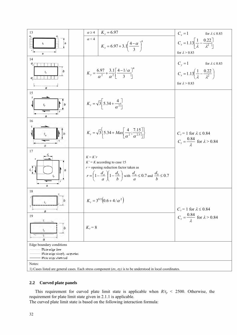
2.2 Curved plate panels
This requirement for curved plate limit state is applicable when R/tp < 2500. Otherwise, the requirement for plate limit state given in 2.1.1 is applicable. The curved plate limit state is based on the following interaction formula:
32
0.13
2
_
25.1
_
PeH
c
PeHax
axc
RCRC
(2-2)
where: ax – applied axial stress to the cylinder corresponding to the curved plate panel, in [N/mm2]. In
case of tensile axial stresses, σax = 0; Cax, C – Buckling reduction factor of the curved plate panel, as defined in Table 2.2.
The stress multiplier factor γc of the curved plate panel needs not be taken less than the stress multiplier factor γc for the expanded plane panel according to 2.1.1
Table 2.2 Buckling Factor and reduction factor for curved plate panel with R/tp < 2500
Case Aspect ratio Buckling factor K Reduction factor C
pt
R
R
d5.0
pRt
dK
2
3
21
1
pt
R
R
d5.0
p
p
p Rt
d
R
t
R
d
Rt
dK
22
4.03267.0
For general application:
Cax = 1 for 0.25
Cax = 1.233–0.933 for 0.25 < 1
Cax = 0.3/3 for 1 < 1.5
Cax = 0.2/2 for > 1.5
For curved single fields, e.g. bilge
strake, which are bounded by plane
panels:
Cax = 0.65/2 1.0
pt
R
R
d7.8
5.15.1
367.03.283
ptR
dK
2
pt
R
R
d7.8
pRtR
dK
228.03
C = 1 for 0.4
C = 1.274–0.686 for 0.4 < 1.2
C = 0.65/2 for > 1.2
Explanations for boundary conditions:
–––– Plate edge simply supported.
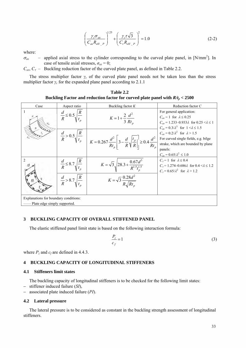
3 BUCKLING CAPACITY OF OVERALL STIFFENED PANEL
The elastic stiffened panel limit state is based on the following interaction formula:
1f
z
c
P (3)
where Pz and cf are defined in 4.4.3.
4 BUCKLING CAPACITY OF LONGITUDINAL STIFFENERS
4.1 Stiffeners limit states
The buckling capacity of longitudinal stiffeners is to be checked for the following limit states: stiffener induced failure (SI), associated plate induced failure (PI).
4.2 Lateral pressure
The lateral pressure is to be considered as constant in the buckling strength assessment of longitudinal stiffeners.
33

4.3 Stiffener idealization
4.3.1 Effective length of the stiffener leff
The effective length of the stiffener leff, in mm, is to be taken equal to:
3
lleff for stiffener fixed at both ends;
lleff 75.0 for stiffener simply supported at one end and fixed at the other;
lleff for stiffener simply supported at both ends.
4.3.2 Effective width of the attached plating beff1
The effective width of the attached plating of a stiffener beff1, in mm, without the shear lag effect is to be taken equal to:
2
22111
bCbCb xx
eff
(4.3.2)
where: Cx1, Cx2 – reduction factor defined in Table 2.1.4-2 calculated for the EPP1 and EPP2 on each side of
the considered stiffener according to case 1 b1, b2 – width of plate panel on each side of the considered stiffener, in [mm].
4.3.3 Effective width of attached plating beff
The effective width of attached plating of stiffeners, beff, in mm, is to be taken as:
sbb seffeff ,min 1 (4.3.3)
where: s – effective width coefficient to be taken as:
1;75.1
1
12.1min
6.1
s
leff
s for 1leff s
s
leffs 407.0 for 1
s
leff
4.3.4 Net thickness of attached plating tp
The net thickness of plate tp, in [mm], is to be taken as the mean thickness of the two attached plating panels.
4.3.5 Effective web thickness of flat bar
For accounting the decrease of stiffness due to local lateral deformation, the effective web thickness of flat bar stiffener, in mm, is to be used for the calculation of the net sectional area, As, the net section modulus, Z, and the moment of inertia, I, of the stiffener and is taken as:
s
b
s
htt effwwredw
122
_ 13
21
(4.3.5)
34
4.3.6 Net section modulus Z of a stiffener
The net section modulus Z of a stiffener, in [cm3], including effective width of plating beff is to be taken equal to: the section modulus calculated at the top of stiffener flange for stiffener induced failure (SI), the section modulus calculated at the attached plating for plate induced failure (PI).
4.3.7 Net moment of inertia I of a stiffener
The net moment of inertia I, in [cm4], of a stiffener including effective width of attached plating beff is to comply with the following requirement:
4
3
1012 pst
I (4.3.7)
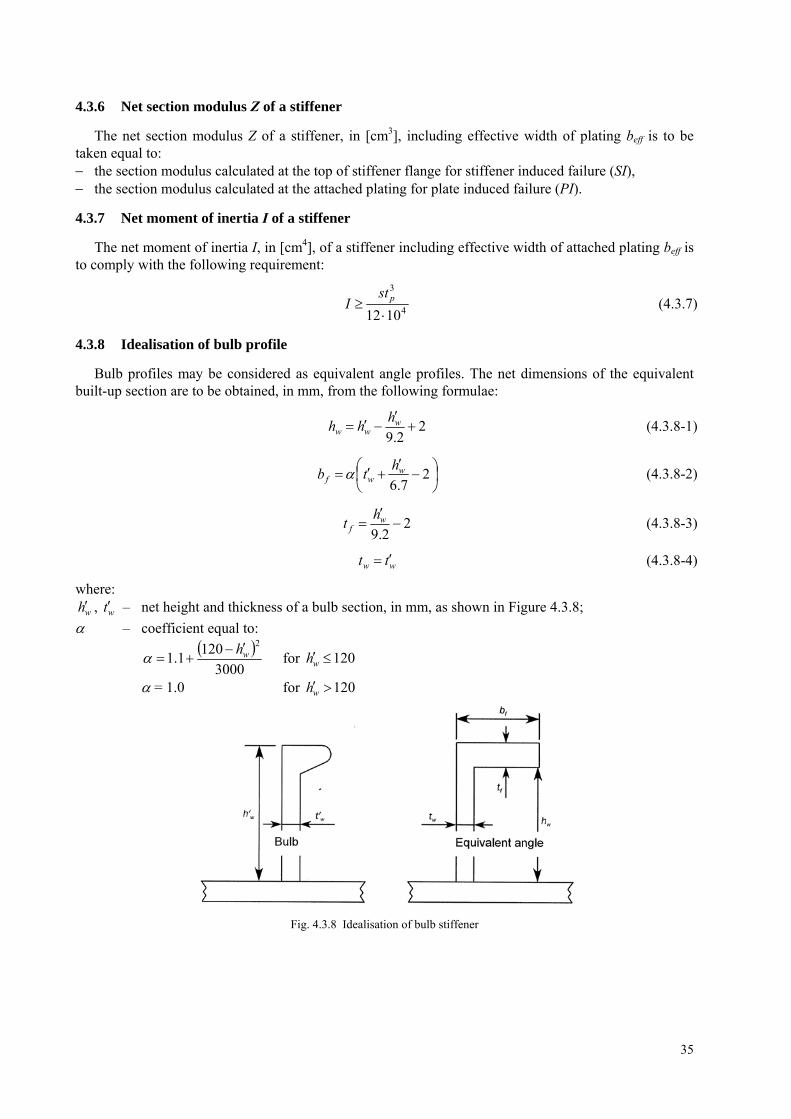
4.3.8 Idealisation of bulb profile
Bulb profiles may be considered as equivalent angle profiles. The net dimensions of the equivalent built-up section are to be obtained, in mm, from the following formulae:
22.9
w
wwh
hh (4.3.8-1)
2
7.6w
wfh
tb (4.3.8-2)
22.9
w
fh
t (4.3.8-3)
ww tt (4.3.8-4)
where:
wh , – net height and thickness of a bulb section, in mm, as shown in Figure 4.3.8; wt – coefficient equal to:
3000
1201.1
2wh
for 120wh
= 1.0 for 120wh
Fig. 4.3.8 Idealisation of bulb stiffener
35
4.4 Ultimate buckling capacity
4.4.1 Longitudinal stiffener limit state
When σa + σb + σw >0, the ultimate buckling capacity for stiffeners is to be checked according to the following interaction formula:
1
eH
bac
R
w (4.4.1)
where: a – effective axial stress, in [N/mm2], at mid-span of the stiffener, defined in 4.4.2; b – bending stress in the stiffener, in [N/mm2], defined in 4.4.3; w – stress due to torsional deformation, in [N/mm2], defined in 4.4.4; ReH – Specified minimum yield stress of the material, in [N/mm2]:
ReH = ReH–S for stiffener induced failure (SI); ReH = ReH–P for plate induced failure (PI).
4.4.2 Effective axial stress σa
The effective axial stress σa, in [N/mm2] at mid-span of the stiffener, acting on the stiffener with its attached plating is to be taken equal to:
speff
spxa Atb
Ast
1
(4.4.2)
where: σx – nominal axial stress, in [N/mm2], acting on the stiffener with its attached plating, calculated
according to S11A. 4.4.1 a) at load calculation point of the stiffener; As – net sectional area, in [mm2], of the considered stiffener.
4.4.3 Bending stress σb
The bending stress in the stiffener σb, in [N/mm2], is to be taken equal to
310 10
Z
MMb (4.4.3)
where: M1 – bending moment, in [N/mm2], due to the lateral load P:
32
1 1024
slP
CM i for continuous stiffener;
32
1 108
slP
CM i for sniped stiffener;
P – lateral load, in [kN/m2], to be taken equal to the static pressure at the load calculation point of the stiffener;
Ci – pressure coefficient: Ci = CSI for stiffener induced failure (SI); Ci = CPI for plate induced failure (PI);
CPI – plate induced failure pressure coefficient: CPI = 1 if the lateral pressure is applied on the side opposite to the stiffener; CPI = –1 if the lateral pressure is applied on the same side as the stiffener;
CSI – stiffener induced failure pressure coefficient: CSI = –1 if the lateral pressure is applied on the side opposite to the stiffener; CSI = 1 if the lateral pressure is applied on the same side as the stiffener;
M0 – bending moment, in [Nm], due to the lateral deformation w of stiffener:
36
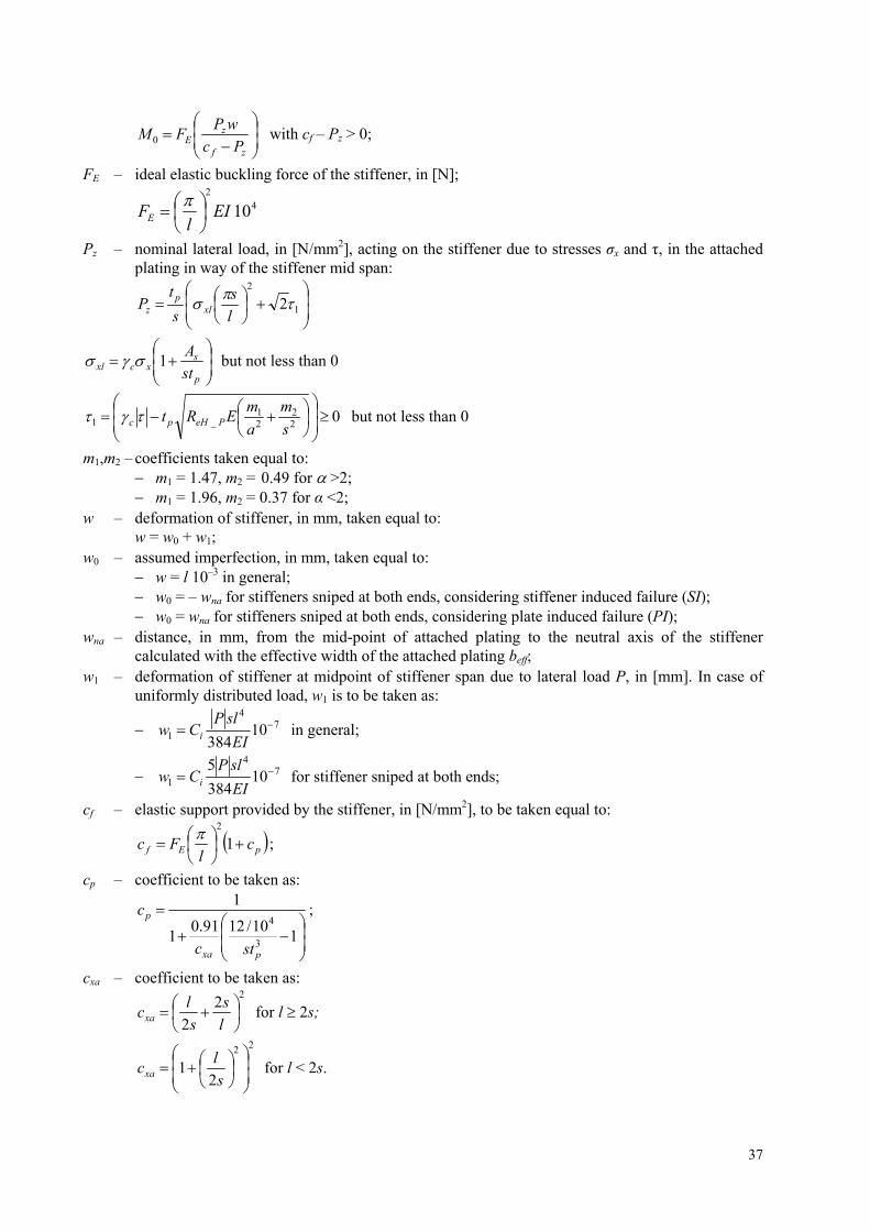
zf
zE Pc
wPFM 0 with cf – Pz > 0;
FE – ideal elastic buckling force of the stiffener, in [N];
42
10 EIl
FE
Pz – nominal lateral load, in [N/mm2], acting on the stiffener due to stresses σx and τ, in the attached plating in way of the stiffener mid span:
1
2
2l
s
s
tP xl
pz
p
sxcxl st
A1 but not less than 0
022
21
_1
s
m
a
mERt PeHpc but not less than 0
m1,m2 – coefficients taken equal to: m1 = 1.47, m2 = 0.49 for >2; m1 = 1.96, m2 = 0.37 for α <2;
w – deformation of stiffener, in mm, taken equal to: w = w0 + w1;
w0 – assumed imperfection, in mm, taken equal to: w = l 10–3 in general; w0 = – wna for stiffeners sniped at both ends, considering stiffener induced failure (SI); w0 = wna for stiffeners sniped at both ends, considering plate induced failure (PI);
wna – distance, in mm, from the mid-point of attached plating to the neutral axis of the stiffener calculated with the effective width of the attached plating beff;
w1 – deformation of stiffener at midpoint of stiffener span due to lateral load P, in [mm]. In case of uniformly distributed load, w1 is to be taken as:
74
1 10384
EI
slPCw i in general;
74
1 10384
5 EI
slPCw i for stiffener sniped at both ends;
cf – elastic support provided by the stiffener, in [N/mm2], to be taken equal to:
pEf cl
Fc
1
2;
cp – coefficient to be taken as:
110/1291.0
1
1
3
4
pxa
p
stc
c ;
cxa – coefficient to be taken as: 2
2
2
l
s
s
lcxa for l 2s;
22
21
s
lcxa for l < 2s.
37
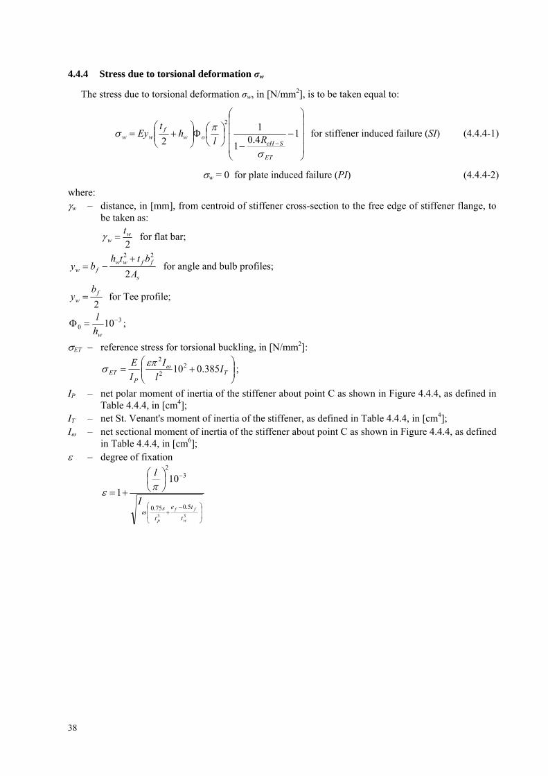
4.4.4 Stress due to torsional deformation σw
The stress due to torsional deformation σw, in [N/mm2], is to be taken equal to:
1
4.01
1
2
2
ET
SeHow
fww Rl
ht
Ey
for stiffener induced failure (SI) (4.4.4-1)
w = 0 for plate induced failure (PI) (4.4.4-2)
where: w – distance, in [mm], from centroid of stiffener cross-section to the free edge of stiffener flange, to
be taken as:
2w
wt
for flat bar;
s
ffwwfw A
btthby
2
22 for angle and bulb profiles;
2f
w
by for Tee profile;
30 10
wh
l;
ET – reference stress for torsional buckling, in [N/mm2]:
T
PET I
l
I
I
E385.0102
2
2 ;
IP – net polar moment of inertia of the stiffener about point C as shown in Figure 4.4.4, as defined in Table 4.4.4, in [cm4];
IT – net St. Venant's moment of inertia of the stiffener, as defined in Table 4.4.4, in [cm4]; I – net sectional moment of inertia of the stiffener about point C as shown in Figure 4.4.4, as defined
in Table 4.4.4, in [cm6]; – degree of fixation
33
5.075.0
32
101
w
ff
p t
te
t
sI
l
38
39
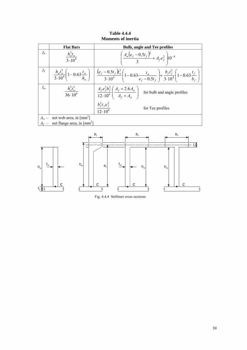
Table 4.4.4 Moments of inertia
Flat Bars Bulb, angle and Tee profiles IP
4
3
103 wwth
422
103
5.0
ff
ffw eAteA
IT
w
www
h
tth63.01
103 4
3
f
fff
ff
wwff
b
ttb
te
ttte63.01
1035.063.01
103
5.04
3
4
3
I
6
33
1036 wwth
wf
wffff
AA
AAbeA 6.2
1012 6
22
for bulb and angle profiles
6
23
1012 fff etb
for Tee profiles
Aw – net web area, in [mm2] Af – net flange area, in [mm2]
Fig. 4.4.4 Stiffener cross sections

ANNEX 3 – HULL GIRDER ULTIMATE BENDING CAPACITY
1 General Assumptions ...................................................................................................................................... 40
2 Incremental-iterative method......................................................................................................................... 40 2.1 Assumptions ............................................................................................................................................. 40 2.2 Procedure .................................................................................................................................................. 41 2.3 Load-end shortening curves...................................................................................................................... 46
3 Alternative methods ........................................................................................................................................ 49 3.1 General...................................................................................................................................................... 49 3.2 Non-linear finite element analysis ............................................................................................................ 50
Symbols: Iy-net – net moment of inertia, in [m4], of the hull transverse section around its horizontal neutral
axis; ZB-net, ZD-net – Section moduli, in [m3], at bottom and deck, respectively; ReH_S – minimum yield stress, in [N/mm2], of the material of the considered stiffener; ReH_P – minimum yield stress, in [N/mm2], of the material of the considered plate; As-net – net sectional area, in [cm2], of stiffener, without attached plating; Ap-net – net sectional area, in [cm2], of attached plating.
1 GENERAL ASSUMPTIONS
1.1 The method for calculating the ultimate hull girder capacity is to identify the critical failure modes of all main longitudinal structural elements:
1.2 Structures compressed beyond their buckling limit have reduced load carrying capacity. All relevant failure modes for individual structural elements, such as plate buckling, torsional stiffener buckling, stiffener web buckling, lateral or global stiffener buckling and their interactions, are to be considered in order to identify the weakest inter-frame failure mode.
2 INCREMENTAL-ITERATIVE METHOD
2.1 Assumptions
In applying the incremental-iterative method, the following assumptions are generally to be made: the ultimate strength is calculated at hull transverse sections between two adjacent transverse webs; the hull girder transverse section remains plane during each curvature increment; the hull material has an elasto-plastic behaviour; the hull girder transverse section is divided into a set of elements, see 2.2.2, which are considered to
act independently. According to the iterative procedure, the bending moment Mi acting on the transverse section at each
curvature value χi is obtained by summing the contribution given by the stress σ acting on each element. The stress σ corresponding to the element strain, ε is to be obtained for each curvature increment from the non-linear load-end shortening curves σ-ε of the element.
These curves are to be calculated, for the failure mechanisms of the element, from the formulae specified in 2.3. The stress σ is selected as the lowest among the values obtained from each of the considered load-end shortening curves σ-ε.
The procedure is to be repeated until the value of the imposed curvature reaches the value χF in [m-1], in hogging and sagging condition, obtained from the following formula:
nety
yF EI
M
003.0 (2.1)
where: My – lesser of the values MY1 and MY2, in [kNm];
40
netBeHY ZRM 31 10 ;
netDeHY ZRM 32 10
If the value χF is not sufficient to evaluate the peaks of the curve M-χ, the procedure is to be repeated until the value of the imposed curvature permits the calculation of the maximum bending moments of the curve.
2.2 Procedure
2.2.1 General
The curve M –χ is to be obtained by means of an incremental-iterative approach, summarised in the flow chart in Figure 2.2.1.
In this procedure, the ultimate hull girder bending moment capacity, MU is defined as the peak value of the curve with vertical bending moment M versus the curvature χ of the ship cross section as shown in Figure 2.2.1. The curve is to be obtained through an incremental-iterative approach.
Each step of the incremental procedure is represented by the calculation of the bending moment Mi which acts on the hull transverse section as the effect of an imposed curvature χi.
For each step, the value χi is to be obtained by summing an increment of curvature, to the value relevant to the previous step χi – 1.This increment of curvature corresponds to an increment of the rotation angle of the hull girder transverse section around its horizontal neutral axis.
This rotation increment induces axial strains ε in each hull structural element, whose value depends on the position of the element. In hogging condition, the structural elements above the neutral axis are lengthened, while the elements below the neutral axis are shortened, and vice-versa in sagging condition.
The stress σ induced in each structural element by the strain ε is to be obtained from the load-end shortening curve - of the element, which takes into account the behaviour of the element in the non-linear elasto-plastic domain.
The distribution of the stresses induced in all the elements composing the hull transverse section determines, for each step, a variation of the neutral axis position due to the nonlinear σ-ε, relationship. The new position of the neutral axis relevant to the step considered is to be obtained by means of an iterative process, imposing the equilibrium among the stresses acting in all the hull elements on the transverse section.
Once the position of the neutral axis is known and the relevant element stress distribution in the section is obtained, the bending moment of the section Mi around the new position of the neutral axis, which corresponds to the curvature χi imposed in the step considered, is to be obtained by summing the contribution given by each element stress.
The main steps of the incremental-iterative approach described above are summarised as follows (see also Figure 2.2.1): a) Step 1: Divide the transverse section of hull into stiffened plate elements; b) Step 2: Define stress-strain relationships for all elements as shown in Table 2.3.1; c) Step 3: Initialise curvature χ1 and neutral axis for the first incremental step with the value of
incremental curvature (i.e. curvature that induces a stress equal to 1% of yield strength in strength deck) as:
nD
eH
zzE
R
101.01
where: zD – Z coordinate, in m, of strength deck at side; zn – Z coordinate, in m, of horizontal neutral axis of the hull transverse section with
respect to the reference coordinate system defined in S11A.1.2.3 d) Step 4: Calculate for each element the corresponding strain, nii zz and the corresponding
stress σi;
41
e) Step 5: Determine the neutral axis zNA_cur at each incremental step by establishing force equilibrium over the whole transverse section as:
jnetjineti AA (i-th element is under compression, j-th element under tension);
f) Step 6: Calculate the corresponding moment by summing the contributions of all elements as;
curNAinetiUiU zzAM _
g) Step 7: Compare the moment in the current incremental step with the moment in the previous incremental step. If the slope in M-χ relationship is less than a negative fixed value, terminate the process and define the peak value MU. Otherwise, increase the curvature by the amount of and go to Step 4.
42

Fig. 2.2.1 Flow chart of the procedure for the evaluation of the curve M –
43

2.2.2 Modelling of the hull girder cross section
Hull girder transverse sections are to be considered as being constituted by the members contributing to the hull girder ultimate strength.
Sniped stiffeners are also to be modelled, taking account that they do not contribute to the hull girder strength.
The structural members are categorised into a stiffener element, a stiffened plate element or a hard corner element.
The plate panel including web plate of girder or side stringer is idealised into a stiffened plate element, an attached plate of a stiffener element or a hard corner element.
The plate panel is categorised into the following two kinds: longitudinally stiffened panel of which the longer side is in ship's longitudinal direction, and transversely stiffened panel of which the longer side is in the perpendicular direction to ship's
longitudinal direction.
a) Hard corner element:
Hard corner elements are sturdier elements composing the hull girder transverse section, which collapse mainly according to an elasto-plastic mode of failure (material yielding); they are generally constituted by two plates not lying in the same plane.
The extent of a hard corner element from the point of intersection of the plates is taken equal to 20tnet on a transversely stiffened panel and to 0.5 s on a longitudinally stiffened panel, see Figure 2.2.2-1 where: tnet – net thickness of the plate, in [mm]; s – spacing of the adjacent longitudinal stiffener, in [m].
Bilge, sheer strake-deck stringer elements, girder-deck connections and face plate-web connections on large girders are typical hard corners
b) Stiffener element:
The stiffener constitutes a stiffener element together with the attached plate. The attached plate width is in principle: equal to the mean spacing of the stiffener when the panels on both sides of the stiffener are
longitudinally stiffened, or equal to the width of the longitudinally stiffened panel when the panel on one side of the stiffener
is longitudinally stiffened and the other panel is of the transversely stiffened, see Figure 2.2.2-1.
c) Stiffened plate element:
The plate between stiffener elements, between a stiffener element and a hard corner element or between hard corner elements is to be treated as a stiffened plate element, see Figure 2.2.2-1.
The typical examples of modelling of hull girder section are illustrated in Figure 2.2.2-2. Notwithstanding the foregoing principle, these figures are to be applied to the modelling in the vicinity of upper deck, sheer strake and hatch coaming.
Fig. 2.2.2-1 Extension of the breadth of the attached plating and hard corner element
44
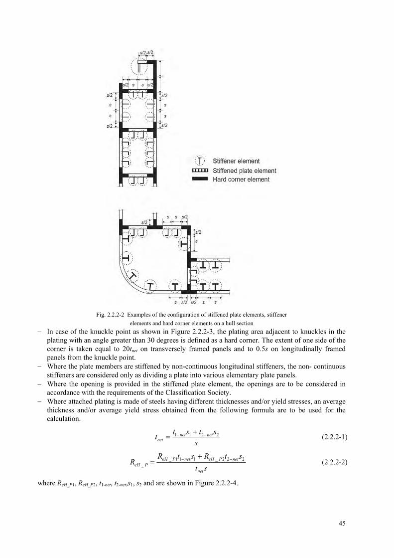
Fig. 2.2.2-2 Examples of the configuration of stiffened plate elements, stiffener
elements and hard corner elements on a hull section
In case of the knuckle point as shown in Figure 2.2.2-3, the plating area adjacent to knuckles in the plating with an angle greater than 30 degrees is defined as a hard corner. The extent of one side of the corner is taken equal to 20tnet on transversely framed panels and to 0.5s on longitudinally framed panels from the knuckle point.
Where the plate members are stiffened by non-continuous longitudinal stiffeners, the non- continuous stiffeners are considered only as dividing a plate into various elementary plate panels.
Where the opening is provided in the stiffened plate element, the openings are to be considered in accordance with the requirements of the Classification Society.
Where attached plating is made of steels having different thicknesses and/or yield stresses, an average thickness and/or average yield stress obtained from the following formula are to be used for the calculation.
s
ststt netnet
net2211
(2.2.2-1)
st
stRstRR
net
netPeHnetPeHPeH
222_111__
(2.2.2-2)
where ReH_P1, ReH_P2, t1-net, t2-net,s1, s2 and are shown in Figure 2.2.2-4.
45

Fig. 2.2.2-3 Plating with knuckle point
Fig. 2.2.2-4 Element with different thickness and yield strength
2.3 Load-end shortening curves
2.3.1 Stiffened plate element and stiffener element
Stiffened plate element and stiffener element composing the hull girder transverse sections may collapse following one of the modes of failure specified in Table 2.3.1 Where the plate members are stiffened by non-continuous longitudinal stiffeners, the stress of the
element is to be obtained in accordance with 2.3.2 to 2.3.7, taking into account the non-continuous longitudinal stiffener. In calculating the total forces for checking the hull girder ultimate strength, the area of non-
continuous longitudinal stiffener is to be assumed as zero. Where the opening is provided in the stiffened plate element, the considered area of the stiffened plate
element is to be obtained by deducting the opening area from the plating in calculating the total forces for checking the hull girder ultimate strength.
For stiffened plate element, the effective width of plate for the load shortening portion of the stress-strain curve is to be taken as full plate width, i.e. to the intersection of other plate or longitudinal stiffener - neither from the end of the hard corner element nor from the attached plating of stiffener element, if any. In calculating the total forces for checking the hull girder ultimate strength, the area of the stiffened plate element is to be taken between the hard corner element and the stiffener element or between the hard corner elements, as applicable.
Table 2.3.1 Modes of failure of stiffened plate element and stiffener element
Element Mode of failure Curve - defined in
Lengthened stiffened plate element
or stiffener element
Elasto-plastic collapse 2.3.2
Shortened stiffener element Beam column buckling
Torsional buckling
Web local buckling of flanged profiles
Web local buckling of flat bars
2.3.3,
2.3.4,
2.3.5,
2.3.6
Shortened stiffened plate element Plate buckling 2.3.7
46
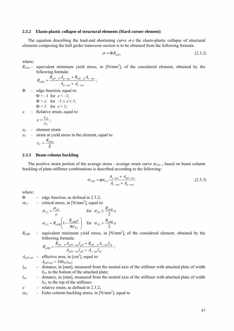
2.3.2 Elasto-plastic collapse of structural elements (Hard corner element)
The equation describing the load-end shortening curve - the elasto-plastic collapse of structural elements composing the hull girder transverse section is to be obtained from the following formula.
eHAR (2.3.2)
where: ReHA – equivalent minimum yield stress, in [N/mm2], of the considered element, obtained by the
following formula:
netsnetp
netsSeHnetpPeHeHA AA
ARARR
__ ;
– edge function, equal to: = –1 for < –1; = for –1 1; = 1 for > 1;
– Relative strain, equal to:
Y
E
;
E – element strain Y – strain at yield stress in the element, equal to:
E
ReHAY
2.3.3 Beam column buckling
The positive strain portion of the average stress - average strain curve CR1– based on beam column buckling of plate-stiffener combinations is described according to the following:
netpnets
netpEnetsCCR AA
AA
11 (2.3.3)
where: – edge function, as defined in 2.3.2; C1 – critical stress, in [N/mm2], equal to:
1
1E
C for 21eHB
ER
11 4
1E
eHBeHBC
RR
for
21eHB
ER
ReHB – equivalent minimum yield stress, in [N/mm2], of the considered element, obtained by the following formula:
sEnetspEnetpEI
sEnetsSeHpEnetpEIPeHeHB lAlA
lARlARR
__ ;
ApEI-net – effective area, in [cm2], equal to: ApEI-net = 10bE1tnet;
lpE – distance, in [mm], measured from the neutral axis of the stiffener with attached plate of width bE1 to the bottom of the attached plate;
lsE – distance, in [mm], measured from the neutral axis of the stiffener with attached plate of width bE1 to the top of the stiffener;
– relative strain, as defined in 2.3.2; E1 – Euler column buckling stress, in [N/mm2], equal to
47
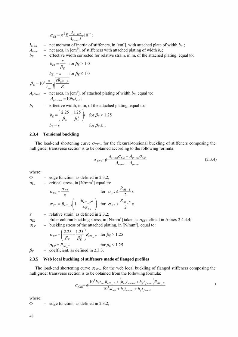
42
21 10
lA
IE
netE
netEE ;
IE-net – net moment of inertia of stiffeners, in [cm4], with attached plate of width bE1; AE-net – net area, in [cm2], of stiffeners with attached plating of width bE; bE1 – effective width corrected for relative strain, in m, of the attached plating, equal to:
EE
sb
1 for E > 1.0
bE1 = s for E 1.0
E
R
t
s PeH
netE
_310
ApE-net – net area, in [cm2], of attached plating of width bE, equal to:
netEnetpE tbA 10 ;
bE – effective width, in m, of the attached plating, equal to:
sbEE
E
2
25.125.2
for E > 1.25
bE = s for E 1
2.3.4 Torsional buckling
The load-end shortening curve CR2- for the flexural-torsional buckling of stiffeners composing the hull girder transverse section is to be obtained according to the following formula:
netpnets
CPnetpCnetsCR AA
AA
22 (2.3.4)
where: – edge function, as defined in 2.3.2; C2 – critical stress, in [N/mm2] equal to:
2
2E
C for _ SE
22eHR
2
__2 4
1E
SeHSeHC
RR
for 2
_2
SeHE
R
– relative strain, as defined in 2.3.2; E2 – Euler column buckling stress, in [N/mm2] taken as ET defined in Annex 2 4.4.4; CP – buckling stress of the attached plating, in [N/mm2], equal to:
PeHEE
CP R _2
25.125.2
for E > 1.25
CP = ReH_P for E 1.25 E – coefficient, as defined in 2.3.3.
2.3.5 Web local buckling of stiffeners made of flanged profiles
The load-end shortening curve CR3- for the web local buckling of flanged stiffeners composing the hull girder transverse section is to be obtained from the following formula:
netffnetwwnet
SeHnetffnetwwePeHnetECR tbthst
RtbthRtb
3
__3
3 10
10 *
where: – edge function, as defined in 2.3.2;
48
bE – effective width, in [m], of the attached plating, as defined in 2.3.3; hwe – effective height, in mm, of the web, equal to:
wEE
we hh
2
25.125.2
for E 1.25;
hwe = hw for E < 1.25;
w – E
R
t
h SeH
netw
ww
_
– relative strain, as defined in 2.3.2.
2.3.6 Web local buckling of stiffeners made of flat bars
The load-end shortening curve CR4- for the web local buckling of flat bar stiffeners composing the hull girder transverse section is to be obtained from the following formula:
netsnetp
CnetsCPnetpCR AA
AA
44
(2.3.6)
where: – edge function, as defined in 2.3.2; CP – buckling stress of the attached plating, in [N/mm2], as defined in 2.3.4; C4 – critical stress, in [N/mm2], equal to:
4
4E
C for _ SE ;
24eHR
4
__4 4
1E
SeHSeHC
RR
for 2
_4
SeHE
R ;
C4 – local Euler buckling stress, in [N/mm2], equal to: 2
4 160000
w
netwE h
t ;
– relative strain, as defined in 2.3.2.
2.3.7 Plate buckling
The load-end shortening curve CR5- for the buckling of transversely stiffened panels composing the hull girder transverse section is to be obtained from the following formula:
2
22_51
111.025.125.2
min_
E
R
EEPeHCR l
s
l
sR
PeH
(2.3.7)
where: – edge function, as defined in 2.3.2; E – coefficient, as defined in 2.3.3; s – plate breadth, in [m], taken as the spacing between the stiffeners; l – longer side of the plate, in [m].
3 ALTERNATIVE METHODS
3.1 General
3.1.1 Application of alternative methods is to be agreed by PRS prior to commencement. Documentation of the analysis methodology and detailed comparison of its results are to be submitted for review and acceptance. The use of such methods may require the partial safety factors to be recalibrated.
49

50
3.1.2 The bending moment-curvature relationship, M-χ, may be established by alternative methods. Such models are to consider all the relevant effects important to the non-linear response with due considerations of:
a) non-linear geometrical behaviour; b) inelastic material behaviour; c) geometrical imperfections and residual stresses (geometrical out-of-flatness of plate and stiffeners); d) simultaneously acting loads:
bi-axial compression; bi-axial tension; shear and lateral pressure;
e) boundary conditions; f) interactions between buckling modes; g) interactions between structural elements such as plates, stiffeners, girders, etc.; h) post-buckling capacity; i) Overstressed elements on the compression side of hull girder cross section possibly leading to local
permanent sets/buckle damages in plating, stiffeners etc. (double bottom effects or similar).
3.2 Non-linear finite element analysis
3.2.1 Advanced non-linear finite element analyses models may be used for the assessment of the hull girder ultimate capacity. Such models are to consider the relevant effects important to the non-linear responses with due consideration of the items listed in 3.1.2.
3.2.2 Particular attention is to be given to modelling the shape and size of geometrical imperfections. It is to be ensured that the shape and size of geometrical imperfections trigger the most critical failure modes.
List of amendments effective as of 1 July 2017
Item Title/Subject Source
6.3 Whipping phenomenon EMSA inspection

![Ultimate strength study of composite plates...Vf Fiber volume fraction [-] X Longitudinal strength [MPa] Y Transverse strength [MPa] Z Out of plane strength [MPa] CHALMERS, Shipping](https://cdn.vdocument.in/doc/165x107/6125dbbad1c3be144f192874/ultimate-strength-study-of-composite-plates-vf-fiber-volume-fraction-x-longitudinal.jpg)
![productinformation precidur DD11 - thyssenkrupp · Mechanical properties Longitudinal to rolling direction Yield strength R eL [MPa] Tensile strength R m [MPa] Elongation A 5 [%]](https://cdn.vdocument.in/doc/165x107/5e9f6d129e874a2cf330ac56/productinformation-precidur-dd11-thyssenkrupp-mechanical-properties-longitudinal.jpg)


