Download - Quick Selection Guide - Newcastle | Ezimetal

fir
mlo
k®
bea
ms
1
firmlok® light structural beamsquick selection guide
firm
lok
® bea
ms
2
Nominal
Nominal
Nominal
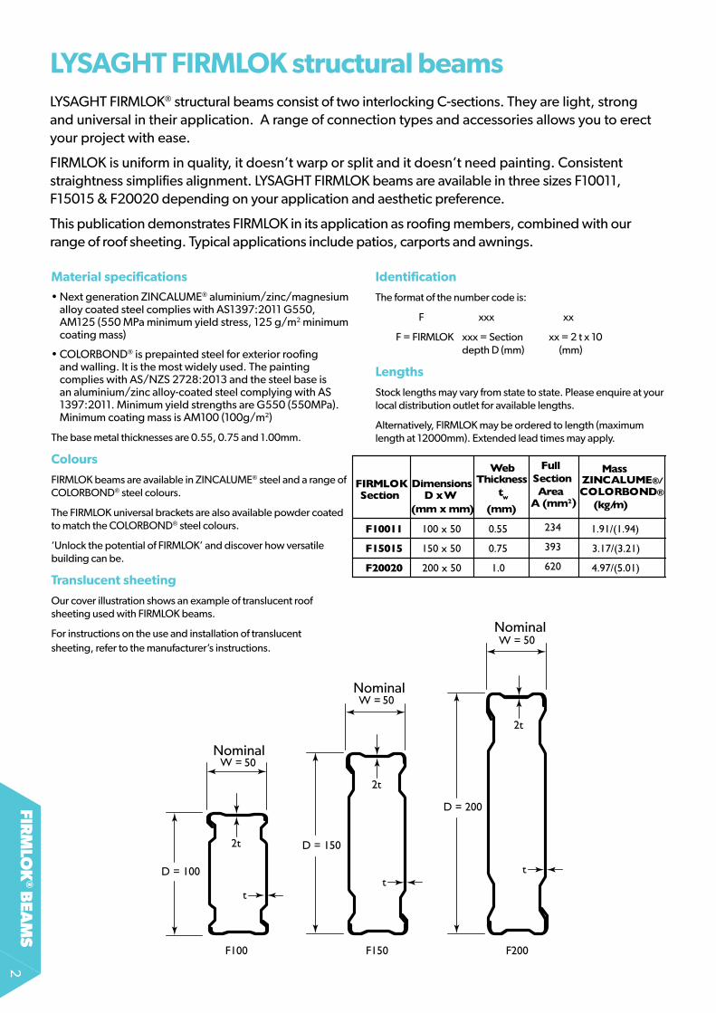
Material specifications
• Next generation ZINCALUME® aluminium/zinc/magnesium alloy coated steel complies with AS1397:2011 G550, AM125 (550 MPa minimum yield stress, 125 g/m2 minimum coating mass)
• colorbond® is prepainted steel for exterior roofing and walling. It is the most widely used. The painting complies with AS/NZS 2728:2013 and the steel base is an aluminium/zinc alloy-coated steel complying with AS 1397:2011. Minimum yield strengths are G550 (550MPa). Minimum coating mass is AM100 (100g/m2)
The base metal thicknesses are 0.55, 0.75 and 1.00mm.
Colours
fIrMLok beams are available in ZINCALUME® steel and a range of colorbond® steel colours.
The fIrMLok universal brackets are also available powder coated to match the colorbond® steel colours.
‘Unlock the potential of fIrMLok’ and discover how versatile building can be.
Translucent sheeting
our cover illustration shows an example of translucent roof sheeting used with fIrMLok beams.
for instructions on the use and installation of translucent sheeting, refer to the manufacturer’s instructions.
lysaghT firMlok structural beams
(mm6)(mm x mm) (mm) A (mm2) (kg/m) (kN) I x (full) Iy (full) Iw Zfx Zex Zy (mm4)
F10011 100 x 50 0.55 234 1.91/(1.94) 7.1 0.347 0.081 48.3 7.05 6.87 3.23
F15015 150 x 50 0.75 393 3.17/(3.21) 10.3 1.256 0.152 232.3 16.91 16.67 6.07
F20020 200 x 50 1.0 620 4.97/(5.01) 16.4 3.374 0.258 742.4 33.99 32.83 10.3 467.1
181.1
63.9
FIRMLOK Section (mm4)
DimensionsD x W
Web Thickness
tw
Full SectionArea
Mass ZINCALUME®/ COLORBOND®
Shear Capacity
φVx
Second Moment of Area
X106X106
Warping Constant
Elastic Section ModulusX103
Open Section Torsion
Constant, Jo(mm3)
LySAGhT fIrMLok® structural beams consist of two interlocking C-sections. they are light, strong and universal in their application. A range of connection types and accessories allows you to erect your project with ease.
fIrMLok is uniform in quality, it doesn’t warp or split and it doesn’t need painting. consistent straightness simplifies alignment. LySAGhT fIrMLok beams are available in three sizes f10011, f15015 & f20020 depending on your application and aesthetic preference.
This publication demonstrates fIrMLok in its application as roofing members, combined with our range of roof sheeting. Typical applications include patios, carports and awnings.
identification
The format of the number code is:
f xxx xx
F = fIrMLok xxx = Section xx = 2 t x 10 depth D (mm) (mm)
lengths
Stock lengths may vary from state to state. Please enquire at your local distribution outlet for available lengths.
Alternatively, fIrMLok may be ordered to length (maximum length at 12000mm). Extended lead times may apply.

fir
mlo
k®
bea
ms
3
firMlok accessoriesLysaght offers a range of fIrMLok beam accessories, to ensure design and construction is as easy and stylish as possible. They can be used to complement a LySAGhT “Quick Selection” roof solution, or purchased individually as part of your individual design.
All visible accessories are available powder coated to match the colour of the fIrMLok beam.
lysaghT firMlok universal brackets for different pitches
Collar Tie BracketlysaghT firMlok apex Bracket
lysaghT Column insertreceiver Channel

firm
lok
® bea
ms
4
firMlok roofing quick selection tablesintroduction
fIrMLok roofing “Quick Selection Tables” provide an easy tool for determining the roof layout of your structure, using fIrMLok beams and LySAGhT cladding.
The tables are divided into three sections; Attached Patios, flat free-standing structures and Pitched free-standing structures. Each section comprises of diagrams and span tables. The diagrams assist with selecting your structure type and the tables determine the span of each member.
When using the Quick Selection tables, member designation is important.
• rafters generally run parallel to the ribs on your cladding and have purlins attached
• Purlins run at ninety degrees to the ribs of your cladding.
Using lysaghT firMlok roofing “Quick selection Tables”
The Quick Selection tables have been developed to be comprehensive and flexible, whilst remaining easy to use. The three sections allow you to design most typical structures with little effort.
Note: The sections for free-standing structures can be used to design similar attached structures, provided correct design of tie back to existing structure is performed.
Translucent sheeting
for instructions on the use and installation of translucent sheeting, refer to the manufacturer’s instructions.
Attached patio
Gabled free-standing
Flat free-standing
Purlin
Purlin
Ra�er
To begin, you will need to determine:
• Structure Type (Patio, Flat free-standing, or Pitched free-standing)
This will indicate which section of the “Quick Selection Tables” is appropriate to your design.
• Wind classification (N1& N2, N3 or N4).
your local building authority can give you guidance on which classification you should design for. Alternatively, you can refer to AS4055-2006.
• Structure size The boundary dimensions
This is all the information you need to begin designing your structure. An experienced user will have no problems using the tables to design each structure.
A first time user may wish to refer to the example at the end of each section.

fir
mlo
k®
bea
ms
5
Design conditions for the tablesgeneral
LySAGhT fIrMLok “Quick Selection Tables” have been prepared in accordance with the appropriate Australian standards. Cladding, beam and connection capacities are based on limit state design and testing at BlueScope Lysaght’s Technology centre. The following standards have been referred too;
AS/NZS 4600:2005 Cold formed steel structures AS/NZS 1170.0-2002 Part 0: General principlesAS/NZS 1170.1-2002 Part 1:Permanent, imposed and other actionsAS/NZS 1170.2-2002 Part 2: Wind ActionsAS 4055-2006 Wind loads for housingAS 1562.1-1992 Sheet roof and wall cladding Part 1: MetalAS 4040.2-1992 Methods of testing sheet roof and wall cladding – resistance to wind pressure for non-cyclone regions• The tables presented in this booklet are for
non-cyclonic conditions only.
• Wind Loads - Design Wind speeds have been based on the classification system used in AS4055. factors used to calculate the design net pressures have been derived from AS1170.2. for each structure, two situations have been considered:
- one side enclosed (typically attached to one side of an existing house) or no more than 50% cross sectional area blocked
- three sides enclosed (typically attached to three sides of an existing house) or more than 75% cross sectional area blocked.
• flat roofs must have a roof slope no greater than 5 degrees. roof slopes beyond 5 degrees may experience greater wind loads than have been designed for.
• Pitched roofs must have a roof slope no greater than 22.5 degrees
• Dead Loads - Self weight of both sheeting and fIrMLok beam have been considered. No allowance for ceilings have been made.
• Live Loads - A Live load of 0.25kPa has been considered to account for the accumulation of hail. No additional live load has been considered. No consideration has been made for concentrated loads arising from maintenance. All cladding spans are based on ‘No foot Traffic’.
• Serviceability - Deflection limit adopted for the design of
fIrMLok beams is; - Dead Load: Span/300 - Wind Load: Span/150 - Live Load: Span/150
for attached patios
• Deflection limit adopted for the design of claddings is: Span/120 + Pitch/30
• LySAGhT fLATDEk® cladding spans may result in noticeable deflections under max. loads.
At low pitches and situations where deflections are deemed critical, spans should be reduced to 75%.
• The capacity of the existing structure to withstand the additional loads arising from the attached patio must be verified by a suitably qualified engineer. It’s advised to check with your local government authority to determine any specific requirements for the attachment to existing structures.
• Patios have not been designed to account for any additional rainwater runoff, other than that falling directly onto its roof area. rainwater must not be distributed from existing roofs onto patios.
• LySAGhT fIrMLok “Quick Selection Tables” have been designed and tested using LySAGhT components.
Maximum spans (mm), for wind loading on attached and free roofs, for structures attached on 1 sideor <50% of cross sectional area blocked. Flat and Pitched (No Foot Traffic)
For structures attached on 3 sides or 75% of cross sectional area blocked. Flat and Pitched (No Foot Traffic)Maximum spans (mm), for wind loading on attached and free roofs,
N2(W33) (W37) N3 (W41) N4 (W50) Allowable
N2(W33) W37 N3 (W41) N4 (W50) Allowable
BMT
BMT
Flat/Pitched Flat/Pitched Flat/Pitched Flat/Pitched
Flat/Pitched Flat/Pitched Flat/Pitched Flat/Pitched
overhang
Span Type
Span Type
overhang
FLATDEK/ FLATDEK II (Qld only)
0.42 Single 5100 5100 4500 3300 600
FLATDEK/ FLATDEK II (Qld only)
0.42 Single 600
End/Internal 4800 4800 4500 3300
End/Internal 4800 4800 4200 32005100 4800 4250 3300
CUSTOM ORB 0.42 Single 1800 1800 1800 1800 300
CUSTOM ORB0.42 Single 1800 1750 1650 1350 300
3 fast's per sheet per support
End/Internal 2700 2700 2700 2500
3 fast's per sheet per support
End/Internal 2600 2400 2150 1600
0.48 Single 1800 1800 1800 1800 350
0.48 Single 1800 1800 1750 1300 350
End/Internal 2700 2700 2700 2700
End/Internal 2700 2700 2650 2100
TRIMDEK
0.42 Single 2400 2400 2400 2400 300
TRIMDEK
0.42 Single 2400 2400 2250 1850 300
End/Internal 3000 3000 3000 3000
End/Internal 3000 3000 2850 2300
0.48 Single 2700 2700 2700 2550 350
0.48 Single 2700 2400 2200 1950 350
End/Internal 3000 3000 3000 3000
End/Internal 3000 3000 2900 2250
SPANDEK 0.42 Single 3000 3000 2950 2550 600
SPANDEK 0.42 Single 2700 2450 2250 1800 600
3 fast's per sheet per support
every rib
every rib
End/Internal 3000 3000 3000 2200
3 fast's per sheet per support
End/Internal 2650 2100 1850 1450
0.48 Single 3000 3000 3000 2850 600
0.48 Single 2950 2800 2600 2200 600
End/Internal 3000 3000 3000 3000
End/Internal 3000 3000 2600 1750
KL700HS
0.42 Single 3300 3300 3200 2550 450
KL700HS0.42 Single 2800 2400 2100 1500 450
clip fixed
End/Internal 3600 3600 3600 3100
clip fixedEnd/Internal 3300 3000 2550 1450
0.48 Single 3300 3300 3300 2850 500
0.48 Single 3250 2650 2300 1750 500
End/Internal 3600 3600 3600 3350
End/Internal 3550 3250 2900 1900
KL700HS 0.42 Single 3900 3900 3800 3450 450
KL700HS0.42 Single 3600 3350 3100 na 450
screw fixed (pan)End/Internal No value present
screw fixed (pan)End/Internal No value present
0.48 Single 4200 4200 4100 3600 500
0.48 Single 3750 3500 3300 2750 500
End/Internal No value present
End/Internal No value present
SPANRIB 0.42 Single 2700 2500 2300 1800 300
SPANRIB0.42 Single 2000 1750 1500 1150 300
(Qld only)End/Internal 3600 3600 3300 2600
(Qld only)End/Internal 2900 2500 2300 1450
0.48 Single 3000 3000 3000 3000 350
0.48 Single 3000 3000 2500 2350 350
End/Internal 3600 3600 3600 3600
End/Internal 3000 3000 2800 1700
MinimumRoof Pitch
MinimumRoof Pitch
5º(1 in 12)
5º(1 in 12)
5º(1 in 12)
5º(1 in 12)
2º(1 in 30)
2º(1 in 30)
2º(1 in 30)
2º(1 in 30)
2º(1 in 30)
1º(1 in 50)
2º(1 in 30)
1º(1 in 50)
2º(1 in 30)
1º(1 in 50)
2º(1 in 30)
1º(1 in 50)
3º(1 in 20)
3º(1 in 20)
Note: All claddings are crest fastened (rib fixed) unless otherwise stated. The design of posts, anchoring of posts and footings does not fall under the scope of this document. This shall be carried out by a suitably qualified person.

firm
lok
® bea
ms
6
Simply supported patios - no cladding overhang
Continuous patios - no cladding overhang
P
Purlin Span
Purlin Span
PurlinSpan
PurlinSpan
PurlinSpan
Patio Width Patio
Width
Patio Width
1, 2
1
Existing dwelling Existing dwelling
Existing dwelling
P
Purlin Span
Purlin Span
PurlinSpan
PurlinSpan
PurlinSpan
Patio Width Patio
Width
Patio Width1
Existing dwelling Existing dwelling
Existing dwelling Cladding overhang
Cladding overhang
Cladding overhang
1, 2
1, 2 1, 2
Maximum Purlin Span (simple spans)No cladding overhang
1500 1800 2100 2400 2700 3000 3300 3600 3900 4200 4500 4800 5100 5400 5700 6000F10011 5134 4831 4589 4389 4220 4075 3947 3834 3734 3642 3560 3484 3414 3350 3290 3234F15015 7883 7418 7047 6740 6480 6257 6061 5888 5733 5593 5466 5349 5242 5143 5051 4966F20020 10959 10312 9796 9369 9009 8698 8426 8185 7969 7775 7598 7436 7288 7150 7022 6903F10011 5134 4831 4589 4389 4220 4075 3947 3834 3734 3642 3560 3484 3414 3350 3290 3231F15015 7883 7418 7047 6740 6480 6257 6061 5888 5733 5593 5466 5349 5242 5143 5051 4966F20020 10959 10312 9796 9369 9009 8698 8426 8185 7969 7775 7598 7436 7288 7150 7022 6903F10011 5134 4831 4589 4389 4220 4075 3903 3736 3588 3456 3338 3231 3134 3046 2964 2888F15015 7883 7418 7047 6740 6480 6257 6061 5836 5604 5397 5212 5045 4893 4753 4625 4507F20020 10959 10312 9796 9369 9009 8698 8426 8185 7894 7601 7339 7102 6886 6689 6508 6341F10011 4669 4301 3979 3719 3505 3324 3168 3032 2913 2806 2711 2624 2545 2473 2407 2346F15015 7169 6726 6218 5810 5474 5189 4945 4733 4545 4379 4229 4094 3971 3858 3754 3659F20020 9965 9378 8767 8188 7710 7307 6961 6660 6395 6159 5948 5757 5583 5424 5278 5143
Reduction factor 0.84 0.82 0.81 0.80 0.79 0.77 0.77 0.76 0.75 0.74 0.74 0.73 0.72 0.71 0.71 0.70Apply to Maximum Purlin Span when patio is attached on three sides
W50(N4)
Wind Category
FIRMLOK Beam Size
Patio Width
W33(N2)
W37
W41(N3)
Purlin Span Purlin Span
Patio Width
Existing dwelling
Cladding overhang
Cladding overhang
PurlinSpan
PurlinSpan
PurlinSpan
Patio Width
Existing dwelling
Purlin Span Purlin Span
Patio Width
Existing dwelling
PurlinSpan
PurlinSpan
PurlinSpan
Patio Width
Existing dwelling
2 2
22
Maximum Purlin Span (continuous spans)
1500 1800 2100 2400 2700 3000 3300 3600 3900 4200 4500 4800 5100 5400 5700 6000F10011 6885 6479 6154 5886 5660 5464 5293 5142 5007 4884 4773 4672 4545 4383 4234 4096F15015 10571 9948 9449 9038 8690 8390 8128 7895 7687 7500 7329 7173 6976 6720 6484 6265F20020 14695 13829 13136 12564 12080 11663 11299 10976 10687 10426 10189 9972 9772 9588 9417 9168F10011 6885 6479 6154 5886 5660 5387 5091 4825 4590 4380 4190 4018 3861 3717 3584 3460F15015 10571 9948 9449 9038 8690 8326 7844 7422 7048 6715 6414 6142 5893 5665 5455 5260F20020 14695 13829 13136 12564 12080 11663 11299 10789 10265 9798 9378 8997 8649 8330 8037 7651F10011 6843 6236 5766 5388 5023 4706 4432 4192 3979 3789 3617 3462 3320 3189 3069 2958F15015 10571 9770 9026 8329 7736 7232 6797 6416 6080 5779 5508 5262 5038 4833 4645 4470F20020 14695 13827 12758 11905 11202 10522 9913 9381 8910 8489 8111 7655 7198 6792 6429 6103F10011 5543 4996 4539 4168 3859 3596 3369 3170 2994 2826 2636 2471 2325 2195 2079 1975F15015 8622 7693 6968 6379 5890 5474 5116 4803 4526 4264 3978 3727 3507 3310 3135 2977F20020 12254 11152 10152 9329 8645 8064 7354 6732 6207 5758 5369 5030 4731 4465 4228 4015
Reduction factor 0.75 0.72 0.69 0.67 0.64 0.62 0.60 0.59 0.57 0.56 0.55 0.54 0.53 0.52 0.51 0.51
FIRMLOKBeam Size
Patio Width
W37
Wind Category
No cladding overhang
Apply to Maximum Purlin Span when patio is attached on three sides
W50(N4)
W33(N2)
W41(N3)
NoTE: Numbers circled in above schematic diagrams refer to acceptable connection type, as illustrated on pages 21-27.
NoTE: Numbers circled in above schematic dia-grams refer to acceptable connection type, as illus-trated on pages 21-27.
Note: Some lengths given in the above table may exceed the maximum size available in your area.

fir
mlo
k®
bea
ms
7
Simply supported patios - with cladding overhang
Continuous patios - with cladding overhang
P
Purlin Span
Purlin Span
PurlinSpan
PurlinSpan
PurlinSpan
Patio Width Patio
Width
Patio Width
1, 2
1
Existing dwelling Existing dwelling
Existing dwelling
P
Purlin Span
Purlin Span
PurlinSpan
PurlinSpan
PurlinSpan
Patio Width Patio
Width
Patio Width1
Existing dwelling Existing dwelling
Existing dwelling Cladding overhang
Cladding overhang
Cladding overhang
1, 2
1, 2 1, 2
Maximum Purlin Span (simple spans) With cladding overhang
1500 1800 2100 2400 2700 3000 3300 3600 3900 4200 4500 4800 5100 5400 5700 6000F10011 4220 4075 3947 3834 3734 3642 3560 3484 3414 3350 3290 3234 3182 3133 3087 3043F15015 6480 6257 6061 5888 5733 5593 5466 5349 5242 5143 5051 4966 4886 4811 4740 4673F20020 9009 8698 8426 8185 7969 7775 7598 7436 7288 7150 7022 6903 6792 6687 6589 6496F10011 4220 4075 3947 3834 3734 3642 3560 3484 3414 3350 3290 3231 3152 3079 3011 2948F15015 6480 6257 6061 5888 5733 5593 5466 5349 5242 5143 5051 4966 4886 4806 4700 4600F20020 9009 8698 8426 8185 7969 7775 7598 7436 7288 7150 7022 6903 6792 6687 6589 6472F10011 4220 4075 3903 3736 3588 3456 3338 3231 3134 3046 2964 2888 2818 2753 2692 2636F15015 6480 6257 6061 5836 5604 5397 5212 5045 4893 4753 4625 4507 4398 4296 4201 4112F20020 9009 8698 8426 8185 7894 7601 7339 7102 6886 6689 6508 6341 6186 6042 5908 5782F10011 3505 3324 3168 3032 2913 2806 2711 2624 2545 2473 2407 2346 2289 2236 2187 2141F15015 5474 5189 4945 4733 4545 4379 4229 4094 3971 3858 3754 3659 3570 3488 3411 3338F20020 7710 7307 6961 6660 6395 6159 5948 5757 5583 5424 5278 5143 5018 4902 4793 4691
Reduction factor 0.79 0.77 0.77 0.76 0.75 0.74 0.74 0.73 0.72 0.71 0.71 0.70 0.69 0.68 0.68 0.67Apply to Maximum Purlin Span when patio is attached on three sides
Wind Category
FIRMLOKBeam Size
Patio Width
W37
W50(N4)
W33(N2)
W41(N3)
Purlin Span Purlin Span
Patio Width
Existing dwelling
Cladding overhang
Cladding overhang
PurlinSpan
PurlinSpan
PurlinSpan
Patio Width
Existing dwelling
Purlin Span Purlin Span
Patio Width
Existing dwelling
PurlinSpan
PurlinSpan
PurlinSpan
Patio Width
Existing dwelling
2 2
22
Maximum Purlin Span (continuous spans) With cladding overhang
1500 1800 2100 2400 2700 3000 3300 3600 3900 4200 4500 4800 5100 5400 5700 6000F10011 5660 5464 5293 5142 5007 4884 4773 4672 4545 4383 4234 4096 3967 3847 3735 3630F15015 8690 8390 8128 7895 7687 7500 7329 7173 6976 6720 6484 6265 6061 5871 5694 5528F20020 12080 11663 11299 10976 10687 10426 10189 9972 9772 9588 9417 9168 8884 8619 8371 8138F10011 5660 5387 5091 4825 4590 4380 4190 4018 3861 3717 3584 3460 3346 3239 3139 3045F15015 8690 8326 7844 7422 7048 6715 6414 6142 5893 5665 5455 5260 5080 4911 4754 4607F20020 12080 11663 11299 10789 10265 9798 9378 8997 8649 8330 8037 7651 7281 6945 6638 6358F10011 5023 4706 4432 4192 3979 3789 3617 3462 3320 3189 3069 2958 2850 2720 2601 2492F15015 7736 7232 6797 6416 6080 5779 5508 5262 5038 4833 4645 4470 4302 4105 3925 3760F20020 11202 10522 9913 9381 8910 8489 8111 7655 7198 6792 6429 6103 5809 5541 5298 5074F10011 3859 3596 3369 3170 2994 2826 2636 2471 2325 2195 2079 1975 1880 1795 1716 1645F15015 5890 5474 5116 4803 4526 4264 3978 3727 3507 3310 3135 2977 2835 2705 2587 2479F20020 8645 8064 7354 6732 6207 5758 5369 5030 4731 4465 4228 4015 3822 3647 3487 3341
Reduction factor 0.64 0.62 0.60 0.59 0.57 0.56 0.55 0.54 0.53 0.52 0.51 0.51 0.50 0.50 0.50 0.49
FIRMLOK Beam Size
Patio Width
W37
Wind Category
Apply to Maximum Purlin Span when patio is attached on three sides
W50(N4)
W33(N2)
W41(N3)
NoTE: Numbers circled in above schematic dia-grams refer to acceptable connection type, as illus-trated on pages 21-27.
NoTE: Numbers circled in above schematic dia-grams refer to acceptable connection type, as illus-trated on pages 21-27.
Note: Some lengths given in the above table may exceed the maximum size available in your area.

firm
lok
® bea
ms
8
Attached patio example 1
Step 1: Required Information before you start
Determine the wind area you are in.
Select the boundary dimensions.
Will the patio be attached on one or more sides?
Step 2: Cladding Design
Select your cladding.
Select the maximum span LySAGhT TrIMDEk® roof cladding can do from the table on P5.
Can your cladding span the patio width in one go?
Can the cladding span the patio width in two spans?
Do you want the cladding to overhang?
Step 3: firMlok purlin design
Using the table on p6 ‘Allowable purlin span (simple spans) ‘ determine whether a purlin can span the full 6400mm.
Step 4: Select connection
Determine the type of connection you wish to adopt.
In our example, we will choose wind condition W33 (N2), the boundary is 4200 x 6400mm and we will be attaching on one side only.
We will be choosing TrIMDEk.
TrIMDEk can span 2400mm 0.42BMT or 2700mm 0.48BMT.
2400 & 2700 < 4200mm, therefore TrIMDEk cannot span the width in one span. We will need an extra support.
End spans for TrIMDEk are 3000mm.
2 x (3000) = 6000mm > 4200mm.
yes - TrIMDEk 0.42BMT is ok to span the patio width in two spans.
No - we don’t want any overhang.
for Wind Category = W33 (N2), Patio Width = 4200mm
from the table, f20020 will span 7775mm > 6400mm, there-fore, it will do the span.
refer to the diagrams above the table used to select which con-nection to use. In this case, the table used was allowable purlin span (simple spans) no cladding overhang, and the diagram which resembles your structure should be chosen.
In this case connections 1 or 2 are applicable. See below.
Task:
Determine a suitable patio to cover an existing paved area 4200 x 6400mm.
Patio
Wid
th =
420
0
6400mm
Patio
Wid
th =
420
0
6400mm
Additional support
6400mm
1, 2
Patio
Wid
th =
420
0
6400mm
Patio
Wid
th =
420
0
6400mm
Additional support
6400mm
1, 2
Patio
Wid
th =
420
0
6400mm
Patio
Wid
th =
420
0
6400mm
Additional support
6400mm
1, 2
NoTE: Numbers circled in above schematic diagram refers to acceptable connection type, as illustrated on pages 21 - 27.

fir
mlo
k®
bea
ms
9
Free-standing flat roofs
4
Structure Type 2
Structure Type 3Structure Type 1
Purlin
4
3
5
Purlin LW
Purlin Span
Purlin LW
Purlin
=
=
4Ra�er Span
Purlin LW
=
=
Ra�er LW
=
=
Ra�er LW
Ra�er Ra�er
Purli
n
Purli
n Purlin Span
Ra�er Span
Purlin LW
Purlin LW
=
=Ra�er LW
=Ra�er LW
Beam Ra�erLW
Ra�er
Purli
n
Purli
n Purlin Span
3
4
5
Ra�er
Ra�er Span
Purli
n
Purli
n
Purli
n Purlin Span
Purli
n
33
5
Purlin LW
=
=
Ra�er LW
4
Ra�erRa�er Span
Ra�er Span
Purli
n
Purli
n
Purli
n Purlin Span
3
Purlin
4
5
4
Ra�er
Purlin LW
=Ra�er LW
Beam Ra�er Span
Beam Ra�er Span
Beam Ra�er LW
Purlin
4
33
3
3
Ra�er Span
Purlin LW
Beam Ra�er LW
=Ra�er LW
Beam Ra�erSpan
NoTE: Numbers circled in above schematic diagrams refer to acceptable connection type, as illustrated on pages 21 - 27.

firm
lok
® bea
ms
10
Note:Structure Type 3 has additional Beam rafters. The span of these should be obtained from the tables below, using Beam rafter LW instead of rafter LW.
Max
imu
m P
url
in S
pan
150
018
00
210
02
40
02
70
03
00
03
30
03
60
03
90
04
20
04
50
04
80
05
100
54
00
57
00
60
00
F10
011
407
53
83
43
64
23
48
43
35
03
23
43
133
30
43
29
63
28
91
28
25
276
527
102
65
92
611
25
67F1
50
156
257
58
88
55
93
53
49
514
34
96
64
811
467
34
55
04
43
94
33
84
246
416
14
08
24
00
93
94
1F2
00
20
86
98
818
57
775
743
67
150
69
03
66
876
49
66
32
56
171
60
30
59
02
578
45
675
557
45
479
F10
011
407
53
83
43
64
23
48
43
35
03
23
13
079
29
48
28
31
272
82
63
52
55
124
7424
04
23
40
22
81
F15
015
62
575
88
85
59
35
34
95
143
49
66
48
06
46
00
44
184
25
64
111
397
93
85
937
50
36
49
35
57F2
00
20
86
98
818
57
775
743
67
150
69
03
66
876
472
62
155
98
657
81
55
95
54
26
527
25
130
49
99
F10
011
407
537
36
34
56
32
31
30
46
28
88
275
32
636
25
32
243
92
35
62
28
12
213
215
02
09
32
04
0F1
50
156
257
58
36
53
975
04
547
53
45
074
29
64
112
39
49
38
05
367
53
557
34
51
33
53
32
63
315
6F2
00
20
86
98
818
576
01
710
26
68
96
34
16
04
257
82
55
53
53
49
516
65
00
04
85
047
124
58
54
46
8F1
00
113
324
30
32
28
06
26
2424
732
34
62
23
62
141
20
5719
82
1913
1793
168
815
94
1510
143
4F1
50
155
189
473
34
379
40
94
38
58
36
59
34
88
33
38
32
072
979
2780
26
05
245
22
315
219
32
08
3F2
00
20
7307
66
60
615
957
575
424
514
34
90
24
69
14
50
64
34
14
193
40
59
39
113
69
33
49
83
32
2
Red
uctio
n fa
ctor
0.7
70.
760.
740.
730.
71
0.70
0.6
80.
670.
65
0.6
40.
62
0.6
10.
60
0.5
80.
570.
56
Ap
ply
to m
axim
um p
urlin
sp
an w
hen
stru
ctur
e is
att
ache
d o
n th
ree
sid
es o
r 75
% o
f cro
ss s
ectio
nal a
rea
is b
lock
ed.
W3
7
Pu
rlin
Lo
ad W
idth
W4
1
W5
0
Win
d
Cat
ego
ryFI
RM
LOK
B
eam
Siz
e
W3
3
Max
imu
m R
a�er
Sp
an (s
imp
le s
pan
s)
12
12
12
12
12
12
12
12
12
F10
011
43
89
42
074
131
39
59
392
437
61
375
33
597
36
08
34
58
34
84
33
39
337
53
23
53
278
314
23
192
30
59
F15
015
674
06
46
06
34
26
079
60
25
5774
576
25
52
35
54
15
310
53
49
512
75
182
49
675
03
44
82
54
90
14
69
8F2
00
20
80
90
89
80
768
28
45
073
53
80
2770
80
7678
68
48
738
26
64
67
127
64
69
69
04
63
1267
076
170
65
30
F10
011
43
89
42
074
131
39
59
392
437
61
375
33
597
36
08
34
58
34
84
33
39
337
53
23
53
278
314
23
192
30
59
F15
015
64
46
64
60
611
66
079
58
39
5774
55
98
55
23
53
86
53
105
198
512
75
02
84
967
487
64
82
547
36
46
98
F20
02
075
798
98
07
197
84
50
68
89
80
276
634
7678
64
1673
82
62
28
712
76
06
26
90
45
914
6707
578
06
53
0F1
00
114
38
94
207
413
13
95
93
924
376
137
53
35
973
576
34
58
34
183
33
93
28
03
23
53
158
314
23
04
93
05
9F1
50
156
03
26
46
057
04
607
95
42
657
745
187
55
23
497
85
310
479
45
127
46
29
49
674
48
14
82
54
347
46
98
F20
02
07
102
875
567
45
82
976
457
790
96
217
7574
60
1372
795
837
7018
567
767
85
55
31
657
45
397
638
2F1
00
113
83
33
82
63
55
03
60
03
32
23
42
03
134
327
12
975
307
92
814
29
05
267
627
54
25
55
26
23
244
82
50
6F1
50
155
271
587
44
94
85
52
84
679
52
51
44
52
50
22
42
56
476
04
08
54
487
393
34
25
237
974
04
53
675
38
63F2
00
20
63
00
7692
59
84
723
657
25
68
56
55
02
65
32
53
04
62
52
512
86
00
64
96
857
88
48
245
59
34
69
25
416
Red
uctio
n fa
ctor
0.8
10.
84
0.8
00.
83
0.79
0.8
20.
780.
81
0.78
0.8
00.
77
0.79
0.76
0.78
0.76
0.7
70.
750.
76
No.
of I
nt. p
urlin
s3
60
03
90
02
40
02
70
03
00
03
30
0
W3
7
W4
1
W5
0
150
0W
ind
C
ate g
ory
FIR
MLO
K
Bea
m S
ize
Ra�
er L
oad
Wid
th
W3
3
180
02
100
12
12
12
311
42
98
53
04
32
917
297
92
85
547
82
45
83
467
34
479
457
44
38
36
04
263
71
59
26
62
26
58
176
09
43
114
29
85
30
43
29
172
979
28
55
46
09
45
83
4492
447
94
38
34
38
35
65
663
71
55
41
62
26
54
33
60
94
29
45
29
85
28
40
29
1727
45
28
30
42
25
45
83
411
34
479
40
09
437
05
273
62
075
157
60
46
50
49
58
98
23
53
240
22
267
23
08
218
92
22
33
56
53
69
93
46
43
55
13
371
34
174
570
52
56
44
58
50
89
43
55
49
04
0.75
0.75
0.74
0.74
0.73
0.73
48
00
42
00
45
00
Ap
ply
to m
axim
um ra
�er s
pan
whe
n st
ruct
ure
is a
ttac
hed
on
thre
e si
des
or 7
5%
of c
ross
sec
tiona
l are
a is
blo
cked
.
12
12
12
392
437
61
38
34
36
65
375
33
53
55
511
5774
53
875
617
527
15
45
36
54
373
22
64
177
151
63
01
69
91
36
82
33
473
570
32
173
44
53
09
95
100
515
84
978
49
54
48
65
467
06
131
675
66
013
65
88
59
04
627
73
26
52
82
13
140
26
33
30
2724
69
46
99
424
44
58
03
96
14
471
3714
574
457
04
56
29
53
2455
21
49
91
23
90
184
82
23
117
25
20
91
1617
35
96
278
03
35
62
595
314
624
33
48
33
3737
45
103
48
84
22
83
270
0.6
20.
51
0.6
00.
50
0.5
80.
50
42
00
45
00
48
00
Max
imu
m R
a�er
Sp
an (c
on
tin
uo
us
span
s)
12
12
12
12
12
12
12
12
12
F10
011
55
30
53
01
52
04
49
88
49
44
473
847
28
45
32
45
46
43
574
38
94
207
42
52
407
54
131
39
59
40
22
38
55
F15
015
745
58
139
7078
765
967
7472
756
52
26
95
963
076
69
16
117
64
60
59
46
62
58
578
96
079
56
44
59
19F2
00
20
876
49
970
83
21
94
68
796
59
06
476
68
872
574
168
43
17
198
816
670
06
7927
68
35
770
86
68
275
07F1
00
115
49
65
30
15
148
49
88
48
61
473
84
619
45
32
44
114
28
14
22
94
04
14
06
93
83
33
92
63
65
137
98
34
91
F15
015
69
83
779
76
63
073
146
34
66
914
610
56
575
58
93
62
83
570
36
02
85
53
15
80
35
375
56
02
52
31
53
84
F20
02
08
210
93
42
779
58
872
746
28
48
57
184
815
06
94
87
85
367
44
758
96
56
473
50
64
05
713
46
26
16
937
F10
011
50
60
512
847
25
4710
44
50
43
33
42
194
027
40
22
3773
38
51
35
5737
00
337
03
55
83
20
63
40
33
03
8F1
50
156
54
37
191
62
1067
22
59
33
63
38
56
92
60
145
48
057
375
29
15
487
512
15
194
49
674
937
48
274
571
F20
02
076
9387
55
730
58
297
69
9279
09
673
375
746
512
7279
63
20
7018
615
267
85
60
03
657
45
86
86
143
F10
011
43
00
413
33
993
373
637
46
34
26
35
243
174
33
00
287
53
109
25
88
29
45
23
52
278
92
156
257
419
90
F15
015
577
76
127
54
49
56
96
517
35
28
24
937
48
66
473
14
32
54
55
13
89
34
39
03
53
94
195
324
43
872
29
94
F20
02
06
82
376
926
48
072
36
62
03
68
56
597
36
53
257
755
814
55
99
52
32
54
40
475
65
29
44
36
05
160
40
25
Red
uctio
n fa
ctor
0.79
0.74
0.78
0.7
10.
760.
68
0.74
0.6
40.
720.
61
0.70
0.5
90.
68
0.5
60.
66
0.5
40.
64
0.5
2
Win
d
Cat
ego
ryFI
RM
LOK
B
eam
Siz
e15
00
180
02
100
24
00
27
00
30
00
33
00
36
00
39
00
No.
of I
nt. p
urlin
s
W3
3
W3
7
W4
1
W5
0
Ra�
er lo
ad w
idth
Ap
ply
to m
axim
um ra
�er s
pan
whe
n st
ruct
ure
is a
ttac
hed
on
thre
e si
des
or 7
5%
of c
ross
sec
tiona
l are
a is
blo
cked
.

fir
mlo
k®
bea
ms
11
In our example, we will choose wind condition W41 (N3), the boundary is 6100 x 6600mm and the structure is not blocked.
We will be choosing fLATDEk.
fLATDEk can span 4500mm 0.42mm BMT.
4500 < 6600mm, therefore fLAtdek cannot. We will need an extra support.
End spans for fLATdek are 4500mm.
2 x (4500) = 9000mm > 6600mm.
yes - fLATDEk is ok to span the structure length in two spans.
We are Structure Type 2.
Using Structure 2 diagrams: for Wind Category W41 (N3) Purlin LW = 3300 Purlin span = 6100 f20020 will span 6042 = 6042 ≤ 6100 Therefore, not suitable.
Purlin LW = 2200 Purlin span = 6100 7434 ≥ 6100, therefore ok
for Wind Category W41 (N3), rafter LW = 3050 rafter Span = 6600mm Number of intermediate purlins = 2 from the table for f20020 - Simple span = 7010 ≥ 6100, therefore, it will do the span.
In this case connections 3 or 4 are applicable.
It is ok to span the structure length in two spans.
We are Structure Type 2.Using Structure 2 diagrams:for Wind Category W41 (N3)Purlin LW = 3300 Purlin span = 6100f20020 will span 6042 = 6042 ≤ 6100 Therefore, not suitable.Purlin LW = 2200 Purlin span = 61007434 ≥ 6100, therefore ok
for Wind Category W41 (N3),rafter LW = 3050 rafter Span = 6600mmNumber of intermediate purlins = 2from the table for f20020 - Simple span = 7010 ≥ 6100 , therefore,it will do the span. In this case connections 3 or 4 are applicable.
Free-standing flat roof: Example 2Task: Determine a suitable freestanding carport to cover an existing slabbed area 6100 x 6600mm
Worked examplesteps
Step 1: Required Information before you start Determine the wind area you are in.
Select the boundary dimensions.
Will the structure be attached on one or more sides or blocked by 75% or greater?
Step 2: Cladding Design Select your cladding.
Select your cladding direction.
Select the maximum span fLATDEk can do from the table on page 5.
Can your cladding span the length in one span?
Can the cladding span the length in two spans?
Step 3: Structure type Select your structure type from the diagrams on
page 9.
Step 4: firMlok purlin design Using the table on page 10 ‘Maximum Purlin
Span‘ determine whether a purlin can span the full 6100mm at the given spacing.
Add additional purlin and see if the purlin design is adequate.
Step 5: Rafter design Using the table on page 10 Maximum rafter Span
(simple spans) determine whether the rafter can span the full length.
Step 6: Select connection for your structure type, the diagrams on page 8
indicate which connections you can have.
610
0m
m
6600mm
Additional support
4 3
Purlin LW
Purlin LW
Purli
n sp
anPu
rlin
span
Ra�er Span
Ra�e
r LW
Cladding direction
610
0m
m
6600mm
Additional support
4 3
Purlin LW
Purlin LW
Purli
n sp
anPu
rlin
span
Ra�er Span
Ra�e
r LW
610
0m
m
6600mm
Additional support
4 3
Purlin LW
Purlin LW
Purli
n sp
anPu
rlin
span
Ra�er Span
Ra�e
r LW
610
0m
m
6600mm
Additional support
4 3
Purlin LW
Purlin LWPu
rlin
span
Purli
n sp
an
Ra�er Span
Ra�e
r LW
610
0m
m6600mm
Additional support
4 3
Purlin LW
Purlin LW
Purli
n sp
anPu
rlin
span
Ra�er Span
Ra�e
r LW
610
0m
m
6600mm
Additional support
4 3
Purlin LW
Purlin LW
Purli
n sp
anPu
rlin
span
Ra�er Span
Ra�e
r LW
610
0m
m
6600mm
Additional support
4 3
Purlin LW
Purlin LW
Purli
n sp
anPu
rlin
span
Ra�er Span
Ra�e
r LW

firm
lok
® bea
ms
12
In our example, we will choose wind condition W33 (N2), the boundary is 6000 x 9000mm and the structure is not blocked.
We will be choosing CUSToM orB.
CUSToM orB can span 1800mm 0.42BMT and 0.48BMT
1800 < 6000mm, therefore CUSToM orB cannot span the distance in one span. We will need an extra support.
End spans for CUSToM orB are 2700mm.
2 x (2700) = 5400mm < 6000mm.
Therefore CUSToM orB cannot span the distance in two spans.
3 x (2700) = 8100mm > 6000mm.
Therefore, CUSToM orB is ok to span the structure length in three spans.
We are Structure Type 2.
Using Structure 2 diagrams: for Wind Category W33 (N2)
Purlin LW = 2000 Purlin span = 9000
f20020 will span 7911 ≤ 9000
Therefore, not suitable.
Purlin LW = 1500 Purlin span = 9000
f20020 will span 8698 ≤ 9000
Therefore, not suitable.
Using Structure 2 diagrams: for Wind Category W33 (N2)
Purlin LW = 2000 Purlin span = 4500
f20020 will span 7911 ≥ 4500
or f15015 will span 5691 ≥ 4500
Therefore, both are suitable.
Free-standing flat roof: Example 3Task: Determine a suitable freestanding carport to cover an existing slabbed area 9000 x 6000mm
Worked examplesteps
60
00
mm
9000mm
Purli
n LW
Ra�e
r Sp
an
Purlin span
Purli
n LW
Purlin span
Ra�er LW
Ra�e
r Sp
an
Ra�er LW
Beam Ra�er Span
Ra�e
r Sp
an
Purlin span
Bea
m R
a�er
LW
Bea
m R
a�er
LW
Beam Ra�er Span
Purlin 4
3
5
Ra�
er
Sp
an
Purli
n LW
=Ra�er
LW
Bea
m R
a�er
LW
Beam Ra�er Span
60
00
mm
9000mm
Purli
n LW
Ra�e
r Sp
an
Purlin span
Purli
n LW
Purlin span
Ra�er LW
Ra�e
r Sp
an
Ra�er LW
Beam Ra�er Span
Ra�e
r Sp
an
Purlin span
Bea
m R
a�er
LW
Bea
m R
a�er
LW
Beam Ra�er Span
Purlin 4
3
5
Ra�
er
Sp
an
Purli
n LW
=Ra�er
LW
Bea
m R
a�er
LW
Beam Ra�er Span
60
00
mm
9000mm
Purli
n LW
Ra�e
r Sp
an
Purlin span
Purli
n LW
Purlin span
Ra�er LW
Ra�e
r Sp
anRa�er LW
Beam Ra�er Span
Ra�e
r Sp
an
Purlin span
Bea
m R
a�er
LW
Bea
m R
a�er
LW
Beam Ra�er Span
Purlin 4
3
5
Ra�
er
Sp
an
Purli
n LW
=Ra�er
LW
Bea
m R
a�er
LW
Beam Ra�er Span
60
00
mm
9000mm
Purli
n LW
Ra�e
r Sp
an
Purlin span
Purli
n LW
Purlin span
Ra�er LW
Ra�e
r Sp
an
Ra�er LW
Beam Ra�er Span
Ra�e
r Sp
an
Purlin span
Bea
m R
a�er
LW
Bea
m R
a�er
LW
Beam Ra�er Span
Purlin 4
3
5
Ra�
er
Sp
an
Purli
n LW
=Ra�er
LW
Bea
m R
a�er
LW
Beam Ra�er Span
60
00
mm
9000mm
Purli
n LW
Ra�e
r Sp
an
Purlin span
Purli
n LW
Purlin span
Ra�er LW
Ra�e
r Sp
an
Ra�er LW
Beam Ra�er Span
Ra�e
r Sp
an
Purlin span
Bea
m R
a�er
LW
Bea
m R
a�er
LW
Beam Ra�er Span
Purlin 4
3
5
Ra�
er
Sp
an
Purli
n LW
=Ra�er
LW
Bea
m R
a�er
LW
Beam Ra�er Span
60
00
mm
9000mm
Purli
n LW
Ra�e
r Sp
an
Purlin span
Purli
n LW
Purlin span
Ra�er LW
Ra�e
r Sp
an
Ra�er LW
Beam Ra�er Span
Ra�e
r Sp
an
Purlin span
Bea
m R
a�er
LW
Bea
m R
a�er
LW
Beam Ra�er Span
Purlin 4
3
5
Ra�
er
Sp
an
Purli
n LW
=Ra�er
LW
Bea
m R
a�er
LW
Beam Ra�er Span
Step 1: Required Information before you start
Determine the wind area you are in.
Select the boundary dimensions.
Will the structure be attached on one or more sides or blocked by 75% or greater?
Step 2: Cladding Design
Select your cladding.
Select your cladding direction (typically in the largest direction)
Select the maximum span CUSToM orB can do from the table on p5.
Can your cladding span the length in one span?
Can the cladding span the length in two spans?
Can the cladding span the length in three spans?
Step 3: Structure type
Select your structure type from the diagrams on p. 9.
Step 4: firMlok purlin design
Using the table on p10 ‘Maximum Purlin Span‘ determine whether a purlin can span the full 9000mm at the given spacing.
Add additional purlin and see if the purlin design is adequate.
Alternatively, add an additional rafter and review purlin design. Note: The structure type is now Type 3.
Cladding direction

fir
mlo
k®
bea
ms
13
for Wind Category W33 (N2),rafter LW = 4500 rafter Span = 6000mmNumber of intermediate purlins = 2from the table for f20020 - Simple span = 6226 ≥ 6000 , therefore, it will do the span.
for Wind Category W33 (N2),Beam rafter LW = 3000 Beam rafter Span = 9000mmNumber of intermediate purlins = 1from the table for f20020 - Simple span = 6646 < 9000 , therefore, it will not do the span.
for Wind Category W33 (N2), Beam rafter Span is reduced to 4500mm, therefore ok.
In this case connections 3, 4 or 5 are applicable. See below.
60
00
mm
9000mm
Purli
n LW
Ra�e
r Sp
an
Purlin span
Purli
n LW
Purlin span
Ra�er LW
Ra�e
r Sp
an
Ra�er LW
Beam Ra�er Span
Ra�e
r Sp
an
Purlin span
Bea
m R
a�er
LW
Bea
m R
a�er
LW
Beam Ra�er Span
Purlin 4
3
5
Ra�
er
Sp
an
Purli
n LW
=Ra�er
LW
Bea
m R
a�er
LW
Beam Ra�er Span
60
00
mm
9000mm
Purli
n LW
Ra�e
r Sp
an
Purlin span
Purli
n LW
Purlin span
Ra�er LW
Ra�e
r Sp
an
Ra�er LW
Beam Ra�er Span
Ra�e
r Sp
an
Purlin span
Bea
m R
a�er
LW
Bea
m R
a�er
LW
Beam Ra�er Span
Purlin 4
3
5
Ra�
er
Sp
an
Purli
n LW
=Ra�er
LW
Bea
m R
a�er
LW
Beam Ra�er Span
Step 5: Rafter design
Using the table Maximum rafter Span on p10 (simple spans) determine whether the rafter can span the full length.
Step 6: Beam Rafter Design
Using the table Maximum rafter Span on p10 (simple spans) using Beam rafter load widths instead of beam load Widths determine whether the rafter can span the full length.
Add post to support beam rafter and review Beam rafter design.
Step 7: Select connection
for your structure type, the diagrams on page 9 indicate which connections you can have.
60
00
mm
9000mm
Purli
n LW
Ra�e
r Sp
an
Purlin span
Purli
n LW
Purlin span
Ra�er LW
Ra�e
r Sp
an
Ra�er LW
Beam Ra�er Span
Ra�e
r Sp
an
Purlin span
Bea
m R
a�er
LW
Bea
m R
a�er
LW
Beam Ra�er Span
Purlin 4
3
5
Ra�
er
Sp
an
Purli
n LW
=Ra�er
LW
Bea
m R
a�er
LW
Beam Ra�er Span
60
00
mm
9000mm
Purli
n LW
Ra�e
r Sp
an
Purlin span
Purli
n LW
Purlin span
Ra�er LW
Ra�e
r Sp
an
Ra�er LW
Beam Ra�er Span
Ra�e
r Sp
an
Purlin span
Bea
m R
a�er
LW
Bea
m R
a�er
LW
Beam Ra�er Span
Purlin 4
3
5
Ra�
er
Sp
an
Purli
n LW
=Ra�er
LW
Bea
m R
a�er
LW
Beam Ra�er Span

firm
lok
® bea
ms
14
gable roofs
1010 6
7 7
6
With collar tie
Gable spacingGable spacing
Gable Width
Gable Width
9
7Gable spacing
Gable Width
Gable Width
8
6
9 7Gable spacingMight requiredouble ra�ers
q
Gable width
Gable pitch
q
Gable width
Gable pitch Ra�er length
6
Intermediate purlins where applicable
When checking cladding span, ra�er length mustbe calculated using the following formula:For a 15º gable pitch, Ra�er length = 0.52 x gable widthFor a 22.5º gable pitch, Ra�er length = 0.54 x gable widthNote: These equations are estimations for choosing the cladding only, not precise dimensions for construction.
NOTES: Numbers circled in above schematic diagrams refer to acceptable connection type, as illustrated on pages 21-27.
Collar ties must be placed on all gable rafters. Collar ties must always be positioned in accordance with Connection 10. (p26)
Gable width goes to backside of bracket.

fir
mlo
k®
bea
ms
15
Max
imu
m P
url
in S
pan
- G
able
Str
uct
ure
wit
h C
olla
r Tie
30
00
33
00
36
00
39
00
42
00
45
00
48
00
510
05
40
05
70
06
00
06
30
06
60
06
90
07
20
07
50
07
80
0F1
00
115
075
49
1647
764
65
04
537
44
33
43
39
42
52
417
24
097
40
28
39
63
39
02
38
45
379
037
39
36
91
F15
015
779
275
49
733
37
140
69
66
68
076
66
26
52
96
40
66
29
16
185
60
85
59
91
59
03
58
20
574
15
667
F20
02
010
83
310
49
410
194
99
25
96
83
94
6392
62
907
68
90
587
46
85
98
84
59
83
29
82
06
80
91
798
178
78F1
00
115
075
49
1647
764
65
04
537
44
33
43
39
42
52
417
24
097
40
28
39
63
39
02
38
45
379
037
39
36
91
F15
015
779
275
49
733
37
140
69
66
68
076
66
26
52
96
40
66
29
16
185
60
85
59
91
59
03
58
20
574
15
667
15º
F20
02
010
83
310
49
410
194
99
25
96
83
94
6392
62
907
68
90
587
46
85
98
84
59
83
29
82
06
80
91
798
178
78F1
00
115
075
49
1647
764
65
04
537
44
33
43
39
42
52
417
24
097
40
25
392
73
83
637
50
367
13
59
63
52
6F1
50
157
792
754
973
33
714
06
96
66
807
66
62
65
29
64
06
62
91
618
56
08
55
99
15
85
957
34
56
175
50
6F2
00
20
108
33
104
94
1019
49
92
59
68
39
463
926
29
076
89
05
874
68
59
88
45
98
32
98
20
68
08
079
137
756
F10
011
46
154
416
42
26
40
59
39
1037
763
65
53
54
53
44
43
35
23
26
63
187
311
33
04
42
98
02
919
28
62
F15
015
708
66
86
56
60
86
34
46
109
58
99
570
95
53
65
378
52
33
50
99
497
54
85
947
52
46
51
45
56
44
67F2
00
20
98
51
95
43
9270
89
478
613
83
148
04
47
799
7574
736
97
179
700
36
83
96
687
65
44
64
106
28
3F1
00
115
00
04
84
447
05
45
82
447
04
36
84
275
419
04
111
40
373
96
93
90
53
84
537
88
373
53
68
43
63
6F1
50
1576
7874
38
722
570
35
68
6367
076
56
46
43
36
312
619
96
09
45
99
55
90
35
816
573
45
657
55
83
F20
02
010
673
103
39
100
44
9779
95
41
9324
912
58
94
387
748
617
847
18
33
48
20
68
08
679
727
86
47
762
F10
011
50
00
48
44
470
54
58
24
470
43
68
427
54
190
411
14
037
39
69
39
05
38
45
378
837
35
36
84
36
36
F15
015
7678
743
872
25
703
56
863
6707
65
64
64
33
63
126
199
60
94
59
95
59
03
58
1657
34
56
575
58
32
2.5
ºF2
00
20
1067
310
33
910
04
497
799
54
193
249
125
89
43
8774
86
178
471
83
34
82
06
80
86
7972
78
64
776
2F1
00
115
00
04
84
447
05
45
82
447
04
36
84
275
419
04
111
40
373
935
38
39
375
03
667
35
89
35
163
447
F15
015
7678
743
872
25
703
56
863
6707
65
64
64
33
63
126
199
60
94
59
95
58
59
572
95
60
65
49
25
38
4F2
00
20
1067
310
33
910
04
497
799
54
193
249
125
89
43
8774
86
178
471
83
34
82
06
807
27
89
87
735
758
2F1
00
114
53
14
318
413
23
96
83
82
33
692
357
43
46
63
36
83
277
319
43
116
30
44
297
72
914
28
55
279
9F1
50
156
98
267
53
64
60
62
02
597
357
675
58
25
413
52
59
511
74
98
64
86
447
51
46
46
45
474
45
54
367
F20
02
097
06
94
02
911
287
45
84
198
127
7863
7624
740
572
04
7018
68
46
66
86
65
3763
98
62
676
143
Red
uctio
n fa
ctor
0.8
30.
83
0.8
20.
81
0.8
10.
80
0.79
0.79
0.78
0.78
0.7
70.
77
0.76
0.76
0.76
0.75
0.75
Win
d
Cat
ego
ryFI
RM
LOK
B
eam
Siz
e
W5
0(N
4)
W3
7
Gab
le p
itch
Gab
le W
idth
W3
3(N
2)
W3
7
W4
1(N
3)
810
08
40
08
70
09
00
03
64
43
60
13
55
93
519
55
96
55
29
54
64
54
03
77
7976
86
759
675
113
64
43
60
13
55
93
519
55
96
55
29
54
64
54
03
77
7976
86
759
675
113
45
93
39
63
337
32
80
54
02
53
04
52
105
122
760
874
68
733
672
112
80
927
58
270
92
66
44
38
24
30
34
227
415
66
164
60
52
59
45
58
44
35
91
35
48
35
06
34
675
514
54
475
38
45
32
376
65
7572
748
474
00
35
91
35
48
35
06
34
675
514
54
475
38
45
32
376
65
7572
748
474
00
33
83
33
21
32
63
32
08
52
82
518
55
09
45
00
874
3773
01
717
270
49
274
62
697
26
50
26
05
42
85
42
074
134
40
64
60
275
917
58
1357
14
0.75
0.74
0.74
0.73
Ap
ply
to m
axim
um p
urlin
sp
an w
hen
stru
ctur
e is
att
ache
d o
n th
ree
sid
es o
r 75
% o
f cro
ss s
ectio
nal a
rea
is b
lock
ed.
1010
6
77
6
Wit
h c
oll
ar t
ie
Purli
n Sp
anPu
rlinS
pan
Gab
le s
pac
ing
Gab
le s
pac
ing
Gab
le
Wid
th
Gab
le
Wid
th
97
Purli
n Sp
anPu
rlin
Span
Gab
le s
pac
ing
Gab
le
Wid
thG
able
W
idth
8
697
Gab
le s
pac
ing
Mig
ht re
qui
red
oub
le ra
�ers
θ
Gab
le w
idth
Gab
le p
itch
6
Inte
rmed
iate
pur
lins
whe
re a
pp
licab
le
W5
0(N
4)
W3
3(N
2)
W4
1(N
3)
No
TE: N
umb
ers
circ
led
in a
bov
e sc
hem
atic
dia
gram
s re
fer t
o ac
cep
tab
le c
onne
ctio
n ty
pe,
as
illus
trat
ed o
n p
ages
21-
27.

firm
lok
® bea
ms
16
01
01
01
01
01
01
01
01
01
01
01
01
01
01
01
01
F10
011
46
54
43
08
43
20
40
124
05
537
77
38
41
35
86
36
59
34
25
35
04
32
86
337
13
166
32
53
30
62
314
92
967
30
54
28
82
29
69
28
05
28
9227
36
28
21
2672
2757
26
142
695
25
58
26
39
25
08
F15
015
7874
711
573
08
66
26
68
62
624
06
497
592
36
192
56
56
59
31
54
30
570
55
23
15
50
65
05
85
32
84
90
15
146
476
24
837
4635
45
674
52
14
327
44
144
115
42
06
392
44
011
375
23
83
3F2
00
20
102
89
104
6397
71
974
49
35
29
174
90
06
870
98
56
28
319
776
079
44
710
572
71
65
59
670
96
09
56
23
65
697
58
28
53
51
547
55
05
05
164
478
34
89
14
54
64
64
64
33
14
42
841
40
42
33
F10
011
42
56
39
56
39
51
36
84
370
93
470
35
123
29
43
34
63
145
32
05
30
183
08
32
907
2975
28
112
878
2724
2793
26
4727
162
577
26
45
25
132
58
124
53
25
21
23
99
246
52
34
92
370
23
03
F15
015
720
26
53
46
68
46
08
56
277
573
05
94
25
44
05
66
25
195
54
25
49
86
519
94
80
54
80
84
64
44
478
45
01
419
242
873
947
40
34
372
83
812
35
373
614
33
673
44
13
215
32
84
307
63
143
F20
02
09
64
09
607
915
58
94
887
36
84
277
714
78
94
69
1670
786
279
64
23
5757
58
88
53
20
54
42
49
51
50
61
46
33
4737
43
58
44
55
411
74
20
83
90
23
98
937
1337
94
35
41
36
183
38
83
46
2F1
00
113
927
36
63
36
45
34
123
42
13
213
324
03
05
03
087
29
132
95
827
952
84
42
693
274
52
60
42
65
62
52
32
577
245
224
88
23
86
23
59
23
26
224
52
272
214
22
185
20
50
2092
1967
20
07F1
50
156
64
66
05
16
166
56
35
579
05
307
54
83
50
38
50
674
810
46
114
617
42
38
43
31
39
26
40
123
66
137
40
34
33
35
06
32
34
33
03
30
60
312
62
907
29
69
2770
28
28
26
4727
03
2537
25
89
F20
02
09
03
38
89
88
145
82
86
706
172
25
624
66
38
95
610
573
85
100
52
164
68
347
89
43
35
44
32
40
40
412
837
84
38
68
35
64
36
42
337
13
44
43
199
32
69
30
473
112
29
112
973
2788
28
46
F10
011
33
40
313
93
101
29
23
29
1127
53
2757
26
142
627
249
624
52
23
95
22
66
23
09
211
22
154
198
02
019
186
619
03
176
618
00
1679
1712
160
216
32
153
215
61
1470
1497
1412
143
9F1
50
155
65
35
185
49
88
48
30
43
49
44
45
38
66
39
51
34
89
35
64
318
63
25
52
93
83
00
027
30
278
82
55
42
60
624
01
245
22
26
82
316
215
22
197
20
50
20
90
1957
199
618
7419
1317
99
183
5F2
00
20
65
20
667
15
52
15
647
48
06
49
154
267
43
64
38
48
39
33
35
103
587
32
34
33
03
30
02
30
66
28
05
28
65
263
72
69
124
88
25
40
23
59
240
92
245
22
91
214
22
187
20
52
2092
196
92
007
F10
011
46
53
43
074
32
04
011
40
56
3779
38
40
35
873
65
93
42
63
50
53
287
337
03
167
32
54
30
62
314
92
96
83
05
42
88
32
96
92
807
28
9227
372
82
226
7227
572
613
26
96
25
59
26
40
25
07F1
50
1578
757
116
730
86
62
66
863
624
06
49
95
924
619
25
65
85
93
15
42
957
04
52
31
55
04
50
575
327
49
02
516
847
62
50
2446
364
89
54
52
047
754
414
46
64
43
164
56
24
22
84
46
84
143
F20
02
010
09
210
46
29
58
497
43
917
49
176
88
34
8710
85
44
83
198
293
798
48
071
7692
7875
743
57
700
720
675
35
700
173
82
68
1572
40
66
46
710
66
49
16
816
6347
64
86
62
1661
86
60
92F1
00
114
25
53
95
63
95
13
68
437
08
347
03
513
32
93
33
46
314
53
20
63
019
30
82
29
08
297
52
810
287
927
25
279
42
64
827
162
578
26
44
25
132
579
245
42
52
024
00
246
52
35
024
152
30
2F1
50
1572
03
65
34
66
85
60
876
277
573
05
94
25
44
05
66
35
196
54
25
49
85
52
164
80
45
03
54
64
34
873
45
01
4727
437
24
59
54
257
447
54
150
43
66
40
54
42
65
39
63
417
23
88
24
08
53
80
5F2
00
20
94
55
96
08
89
80
89
49
85
96
84
26
827
679
99
80
06
763
97
770
733
275
59
706
473
676
827
719
16
619
69
53
64
30
65
246
25
86
149
610
35
817
59
61
55
21
58
26
52
575
54
55
02
05
29
4F1
00
113
92
63
66
43
64
43
411
34
22
32
133
241
30
49
30
88
29
122
95
827
96
28
44
26
94
274
62
60
32
657
25
2425
7824
52
25
06
23
85
244
12
32
62
38
022
732
32
62
22
32
275
217
72
227
213
2F1
50
156
64
56
05
16
168
56
36
579
15
307
54
82
50
375
22
54
812
50
06
46
184
813
44
49
46
45
43
00
44
96
416
94
36
14
04
84
241
39
41
412
43
84
33
910
375
537
183
671
35
46
35
94
33
92
35
24F2
00
20
88
62
88
978
415
82
878
05
67
80
37
757
740
874
96
7075
726
467
89
703
16
54
16
48
96
32
36
02
96
129
56
34
59
46
52
92
55
82
49
93
52
64
472
84
98
54
492
473
44
28
14
510
40
91
43
09
F10
011
33
41
313
93
101
29
23
29
1027
53
2757
26
132
62
624
96
25
152
395
2419
23
08
23
36
22
30
22
60
216
22
191
210
12
130
20
45
20
40
199
419
42
194
818
55
190
517
78
1863
170
517
87F1
50
155
65
25
185
524
64
83
04
92
64
547
46
64
43
164
44
44
122
42
5739
56
3952
38
123
66
23
68
43
415
35
53
32
04
337
03
019
317
42
857
30
04
2714
28
53
25
8727
1824
722
59
82
36
924
89
F20
02
07
86
276
26
745
97
101
711
86
687
638
663
4757
34
60
50
52
09
54
9547
805
04
14
424
46
62
411
94
34
03
85
840
633
63
33
82
53
43
33
614
32
58
34
28
310
23
26
32
96
23
113
28
34
29
80
Red
uctio
n fa
ctor
0.6
80.
700.
65
0.67
0.63
0.6
50.
61
0.6
40.
60
0.6
20.
59
0.6
10.
58
0.6
00.
58
0.5
90.
570.
59
0.57
0.5
80.
56
0.5
80.
56
0.57
0.5
60.
570.
56
0.57
0.5
60.
570.
56
0.57
No
.in
term
edia
te p
url
ins
39
00
Gab
le
Pit
ch
15
º
22
.5º
W3
7
W3
7
48
00
Win
d
Cat
ego
ryFI
RM
LOK
B
eam
Gab
le L
oad
Wid
th15
00
180
02
100
24
00
27
00
60
00
510
03
00
03
30
04
20
04
50
05
40
05
70
03
60
0
Max
imu
m G
able
Wid
th -
Gab
le w
ith
co
llar
tie
1010
6
77
6
Wit
h c
oll
ar t
ie
Gab
le LW
Gab
le LW
Gab
le LW
Gab
le LW
Gab
le s
pac
ing
Gab
le s
pac
ing
Gab
le
Wid
th
Gab
le
Wid
th
97
Gab
le s
pac
ing
Gab
le
Wid
thG
able
W
idth
8
697
Gab
le s
pac
ing
Mig
ht re
qui
red
oub
le ra
�ers
θ
Gab
le w
idth
Gab
le p
itch
6
Inte
rmed
iate
pur
lins
whe
re a
pp
licab
le
Ap
ply
to th
e m
axim
um a
llow
able
gab
le w
idth
whe
n th
e st
ruct
ure
is a
ttac
hed
on
thre
e si
des
or 7
5%
of t
he c
ross
sec
tiona
l are
a is
blo
cked
.
W5
0(N
4)
W3
3(N
2)
W4
1(N
3)
W5
0(N
4)
W3
3(N
2)
W4
1(N
3)
No
TE: N
umb
ers
circ
led
in a
bov
e sc
hem
atic
dia
gram
s re
fer t
o ac
cep
tab
le c
onne
ctio
n ty
pe,
as
illus
trat
ed o
n p
ages
21
-27.

fir
mlo
k®
bea
ms
17
11
6
7 7
6
Without collar tie
Gable spacingGable spacing
Gable Width
Gable Width
9
7Gable spacing
Gable Width
Gable Width
8
6
9 7Gable spacingMight requiredouble ra�ers
θ
Gable width
Gable pitch
6
Intermediate purlins where applicable
θ
Gable width
Gable pitch Ra�er length
When checking cladding span, ra�er length mustbe calculated using the following formula:For a 15º gable pitch, Ra�er length = 0.52 x gable widthFor a 22.5º gable pitch, Ra�er length = 0.54 x gable widthNote: These equations are estimations for choosing the cladding only, not precise dimensions for construction.
NoTE: Numbers circled in above schematic diagrams refer to acceptable connection type, as illustrated on pages 21-27.
Gable width goes to backside of bracket.
gable roofs
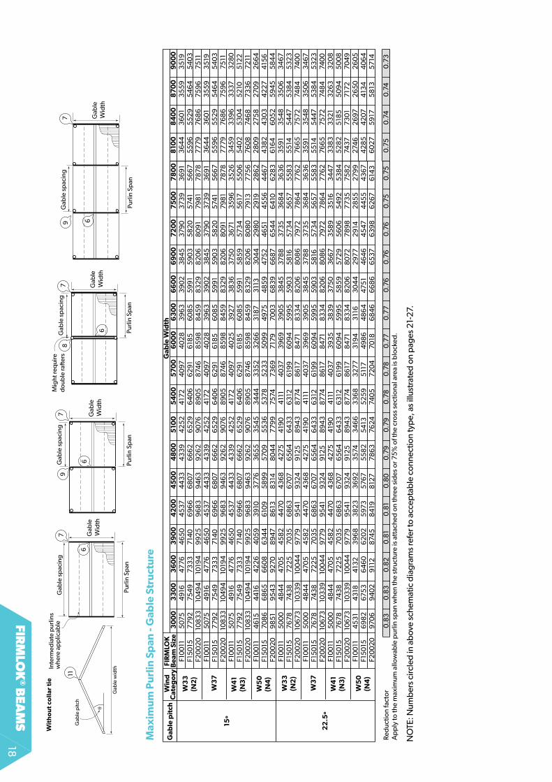
firm
lok
® bea
ms
18
No
TE: N
umb
ers
circ
led
in a
bov
e sc
hem
atic
dia
gram
s re
fer t
o ac
cep
tab
le c
onne
ctio
n ty
pe,
as
illus
trat
ed o
n p
ages
21-
27.
Max
imu
m P
url
in S
pan
- G
able
Str
uct
ure
30
00
33
00
36
00
39
00
42
00
45
00
48
00
510
05
40
05
70
06
00
06
30
06
60
06
90
07
20
07
50
07
80
0F1
00
115
075
49
1647
764
65
04
537
44
33
43
39
42
52
417
24
097
40
28
39
63
39
02
38
45
379
037
39
36
91
F15
015
779
275
49
733
37
140
69
66
68
076
66
26
52
96
40
66
29
16
185
60
85
59
91
59
03
58
20
574
15
667
F20
02
010
83
310
49
410
194
99
25
96
83
94
6392
62
907
68
90
587
46
85
98
84
59
83
29
82
06
80
91
798
178
78F1
00
115
075
49
1647
764
65
04
537
44
33
43
39
42
52
417
24
097
40
28
39
63
39
02
38
45
379
037
39
36
91
F15
015
779
275
49
733
37
140
69
66
68
076
66
26
52
96
40
66
29
16
185
60
85
59
91
59
03
58
20
574
15
667
15º
F20
02
010
83
310
49
410
194
99
25
96
83
94
6392
62
907
68
90
587
46
85
98
84
59
83
29
82
06
80
91
798
178
78F1
00
115
075
49
1647
764
65
04
537
44
33
43
39
42
52
417
24
097
40
25
392
73
83
637
50
367
13
59
63
52
6F1
50
157
792
754
973
33
714
06
96
66
807
66
62
65
29
64
06
62
91
618
56
08
55
99
15
85
957
34
56
175
50
6F2
00
20
108
33
104
94
1019
49
92
59
68
39
463
926
29
076
89
05
874
68
59
88
45
98
32
98
20
68
08
079
137
756
F10
011
46
154
416
42
26
40
59
39
1037
763
65
53
54
53
44
43
35
23
26
63
187
311
33
04
42
98
02
919
28
62
F15
015
708
66
86
56
60
86
34
46
109
58
99
570
95
53
65
378
52
33
50
99
497
54
85
947
52
46
51
45
56
44
67F2
00
20
98
51
95
43
9270
89
478
613
83
148
04
47
799
7574
736
97
179
700
36
83
96
687
65
44
64
106
28
3F1
00
115
00
04
84
447
05
45
82
447
04
36
84
275
419
04
111
40
373
96
93
90
53
84
537
88
373
53
68
43
63
6F1
50
1576
7874
38
722
570
35
68
6367
076
56
46
43
36
312
619
96
09
45
99
55
90
35
816
573
45
657
55
83
F20
02
010
673
103
39
100
44
9779
95
41
9324
912
58
94
387
748
617
847
18
33
48
20
68
08
679
727
86
47
762
F10
011
50
00
48
44
470
54
58
24
470
43
68
427
54
190
411
14
037
39
69
39
05
38
45
378
837
35
36
84
36
36
F15
015
7678
743
872
25
703
56
863
6707
65
64
64
33
63
126
199
60
94
59
95
59
03
58
1657
34
56
575
58
3
22
.5º
F20
02
010
673
103
39
100
44
9779
95
41
9324
912
58
94
387
748
617
847
18
33
48
20
68
08
679
727
86
47
762
F10
011
50
00
48
44
470
54
58
24
470
43
68
427
54
190
411
14
037
393
53
83
937
50
36
673
58
93
516
34
47F1
50
1576
7874
38
722
570
35
68
6367
076
56
46
43
36
312
619
96
09
45
99
55
85
957
29
56
06
54
92
53
84
F20
02
010
673
103
39
100
44
9779
95
41
9324
912
58
94
387
748
617
847
18
33
48
20
68
072
78
98
773
575
82
F10
011
45
31
43
184
132
39
68
38
23
36
923
574
34
66
33
68
327
73
194
311
63
04
42
977
29
142
85
527
99
F15
015
69
82
675
36
46
06
20
25
973
5767
55
82
54
135
25
95
117
49
86
48
64
475
14
64
64
547
44
55
43
67F2
00
20
970
69
40
29
112
874
58
419
812
778
6376
2474
05
720
470
186
84
66
68
66
537
639
86
267
614
3
Red
uctio
n fa
ctor
0.8
30.
83
0.8
20.
81
0.8
10.
80
0.79
0.79
0.78
0.78
0.7
70.
77
0.76
0.76
0.76
0.75
0.75
Ap
ply
to th
e m
axim
um a
llow
able
pur
lin s
pan
whe
n th
e st
ruct
ure
is a
ttac
hed
on
thre
e si
des
or 7
5%
of t
he c
ross
sec
tiona
l are
a is
blo
cked
.
Win
d
Cat
ego
ryFI
RM
LOK
B
eam
Siz
e
W3
7
Gab
le p
itch
Gab
le W
idth
W3
7
810
08
40
08
70
09
00
03
64
43
60
13
55
93
519
55
96
55
29
54
64
54
03
77
7976
86
759
675
113
64
43
60
13
55
93
519
55
96
55
29
54
64
54
03
77
7976
86
759
675
113
45
93
39
63
337
32
80
54
02
53
04
52
105
122
760
874
68
733
672
112
80
927
58
270
92
66
44
38
24
30
34
227
415
66
164
60
52
59
45
58
44
35
91
35
48
35
06
34
675
514
54
475
38
45
32
376
65
7572
748
474
00
35
91
35
48
35
06
34
675
514
54
475
38
45
32
376
65
7572
748
474
00
33
83
33
21
32
63
32
08
52
82
518
55
09
45
00
874
3773
01
717
270
49
274
62
697
26
50
26
05
42
85
42
074
134
40
64
60
275
917
58
1357
14
0.75
0.74
0.74
0.73
11
6
77
6
Wit
ho
ut
coll
ar t
ie
Purli
n Sp
anPu
rlin
Span
Gab
le s
pac
ing
Gab
le s
pac
ing
Gab
le
Wid
th
Gab
le
Wid
th
97
Purli
n Sp
anPu
rlin
Span
Gab
le s
pac
ing
Gab
le
Wid
thG
able
W
idth
8
697
Gab
le s
pac
ing
Mig
ht re
qui
red
oub
le ra
�ers
θ
Gab
le w
idth
Gab
le p
itch
6
Inte
rmed
iate
pur
lins
whe
re a
pp
licab
le
W5
0(N
4)
W3
3(N
2)
W4
1(N
3)
W5
0(N
4)
W3
3(N
2)
W4
1(N
3)

fir
mlo
k®
bea
ms
19
No
TE: N
umb
ers
circ
led
in a
bov
e sc
hem
atic
dia
gram
s re
fer t
o ac
cep
tab
le c
onne
ctio
n ty
pe,
as
illus
trat
ed o
n p
ages
21-
27.
01
01
01
01
01
01
01
01
01
01
01
01
01
01
01
01
F10
011
44
82
45
65
40
92
416
737
883
85
83
54
33
60
93
34
03
40
23
168
32
26
30
21
307
72
89
22
94
627
80
28
30
267
827
28
25
872
635
25
06
25
52
243
024
752
36
124
05
22
99
23
41
224
122
82
F15
015
672
16
84
56
136
624
85
68
057
84
53
135
411
50
09
510
247
52
48
39
45
30
46
154
337
44
184
167
424
44
016
40
90
387
93
95
137
573
82
53
64
337
113
54
13
607
34
46
35
103
35
934
21
F20
02
079
69
912
275
678
32
872
43
77
106
974
7212
667
66
80
06
33
56
45
06
03
96
151
578
25
88
85
55
45
65
65
35
35
45
25
172
52
66
50
075
100
48
574
947
472
14
80
84
59
44
679
447
845
61
F10
011
39
95
40
68
36
4737
153
377
34
39
315
93
217
297
73
03
32
824
287
72
693
274
325
792
62
524
77
25
23
23
88
243
02
307
23
49
22
33
227
42
166
22
06
210
62
144
20
50
20
86
199
820
34
F15
015
59
91
610
15
46
95
570
50
63
515
647
374
824
44
65
45
48
42
374
314
40
40
411
33
86
83
93
937
1537
84
35
80
36
45
34
58
35
22
33
48
34
103
249
33
09
315
73
215
307
43
130
29
94
305
0F2
00
20
7467
813
370
90
7424
674
86
874
63
136
42
95
95
26
06
25
647
575
15
38
45
48
35
154
524
94
95
15
04
447
724
86
14
60
94
69
44
463
454
64
32
94
410
42
08
42
85
40
96
417
13
99
140
67F1
00
113
56
23
62
83
25
13
311
30
103
06
62
817
28
69
26
54
270
52
519
25
65
240
124
46
22
99
23
41
22
08
22
51
212
92
168
20
55
20
94
1992
20
28
1932
1967
1878
1913
182
818
60
1781
1814
F15
015
53
42
54
40
487
64
967
45
154
59
84
22
34
30
23
98
24
05
537
77
38
46
36
01
36
69
34
48
35
123
313
337
53
191
32
51
30
83
314
12
987
30
41
28
98
29
50
28
152
867
273
927
922
670
272
0F2
00
20
69
9572
52
65
01
66
20
60
186
130
56
29
573
45
307
54
05
50
34
512
74
80
14
89
04
59
64
68
14
416
44
974
25
64
33
34
111
418
63
98
04
05
33
86
23
93
337
52
38
21
36
53
37
193
56
036
26
F10
011
28
84
29
36
26
31
26
81
243
624
82
22
80
23
22
214
82
189
20
38
207
719
43
198
018
60
1895
1787
182
217
23
175
416
63
169
416
1116
42
1563
159
215
1815
4714
7815
0714
41
146
8F1
50
154
32
34
40
53
947
40
20
36
55
372
33
417
34
81
32
22
32
82
30
58
311
42
915
29
69
2792
28
42
26
81
273
22
58
32
63
124
96
25
42
2417
246
12
34
52
38
82
278
23
20
22
182
25
82
162
220
2F2
00
20
5763
58
69
52
60
53
59
487
04
96
14
55
54
64
04
29
64
376
407
44
150
38
85
39
56
372
137
88
357
43
64
03
44
43
50
83
327
33
88
32
22
32
80
312
63
184
3037
30
932
956
3010
288
029
34
F10
011
44
81
46
88
40
91
427
937
88
39
62
35
42
370
53
34
13
49
43
169
33
153
02
13
160
28
92
30
25
2779
29
072
677
28
01
25
8727
05
25
06
26
20
243
02
54
12
36
124
702
29
924
04
22
39
234
3F1
50
156
65
070
29
613
56
417
56
80
59
41
53
125
55
65
00
95
23
847
52
497
04
53
147
40
43
39
45
36
416
94
35
94
015
42
00
38
80
40
58
375
63
92
83
64
43
812
35
42
370
53
44
83
60
53
35
935
14F2
00
20
78
189
36
874
22
85
51
710
579
186
84
074
06
66
176
98
36
33
46
624
60
38
63
1657
82
60
48
55
54
58
09
53
53
55
99
517
25
40
85
007
52
374
85
85
079
472
14
937
45
954
80
644
7946
84
F10
011
39
95
417
83
647
38
143
376
35
31
315
83
30
42
977
311
32
82
52
95
52
69
42
816
257
82
69
624
782
59
12
387
249
62
30
624
112
23
22
33
62
166
22
65
210
52
20
32
04
92
143
1997
20
88
F15
015
59
90
62
66
54
69
572
15
06
35
29
647
36
49
54
44
66
46
69
42
374
43
14
03
94
224
38
674
04
537
163
88
63
579
374
43
45
93
618
33
48
35
02
324
83
39
83
158
33
02
307
33
213
29
95
313
2F2
00
20
732
58
35
26
95
576
246
657
705
86
312
66
02
59
52
62
25
56
475
90
55
38
35
63
05
153
53
90
49
52
517
947
71
49
91
46
104
82
14
46
44
667
43
29
45
29
42
074
40
14
09
64
28
33
99
34
176
F10
011
35
62
372
53
25
23
40
23
010
314
92
816
29
45
26
55
277
72
518
26
35
240
22
511
22
99
240
42
210
23
102
129
22
272
057
215
119
9220
82
1931
20
20
187
719
64
1827
1911
1781
1863
F15
015
53
42
55
88
487
65
100
45
1647
23
42
244
418
39
82
416
537
77
39
51
36
01
376
83
44
83
607
33
133
46
53
193
33
39
30
84
32
26
29
86
312
32
897
30
30
28
162
94
527
40
28
66
267
027
94
F20
02
06
863
744
66
50
067
98
60
186
293
563
05
887
53
075
55
15
03
55
26
64
80
05
02
04
59
54
80
64
416
46
184
25
54
44
94
111
43
00
39
80
4163
38
62
40
39
375
33
92
53
65
33
819
35
61
372
3F1
00
112
88
33
016
26
31
275
324
372
54
82
28
02
38
42
149
224
72
03
82
132
194
42
03
318
61
194
617
89
1870
172
218
02
166
517
41
1611
168
515
6316
35
1519
158
914
7815
4714
41
150
8F1
50
154
324
45
23
39
474
128
36
55
38
21
34
183
575
32
22
337
03
05
83
198
29
163
04
927
90
29
192
68
12
80
52
58
327
01
249
62
611
2417
25
28
23
45
245
22
278
23
84
22
172
319
216
222
62
F20
02
057
636
027
52
61
55
03
487
15
09
44
557
476
54
29
64
492
4074
42
63
38
86
40
6337
20
38
91
357
437
38
34
44
36
01
33
28
347
93
22
13
36
83
125
32
69
30
38
317
62
956
309
128
81
3014
Red
uctio
n fa
ctor
0.7
10.
69
0.70
0.6
90.
700.
69
0.70
0.6
90.
69
0.6
90.
69
0.6
90.
69
0.6
90.
69
0.6
90.
69
0.6
90.
69
0.6
90.
69
0.6
90.
69
0.6
90.
69
0.6
90.
69
0.6
90.
69
0.6
90.
69
0.6
9
22
.5º
15
º
Gab
le
Pit
ch
W3
7
54
00
57
00
36
00
39
00
No
. in
term
edia
te p
url
ins
W3
7
48
00
Win
d
Cat
ego
ryFI
RM
LOK
B
eam
Siz
eG
able
Lo
ad W
idth
150
018
00
210
02
40
02
70
06
00
05
100
30
00
33
00
42
00
45
00
Max
imu
m G
able
Wid
th -
Gab
le w
ith
ou
t co
llar
tie
11
6
77
6
Wit
ho
ut
coll
ar t
ie
Gab
le LW
Gab
le LW
Gab
le LW
Gab
le LW
Gab
le s
pac
ing
Gab
le s
pac
ing
Gab
le
Wid
th
Gab
le
Wid
th
97
Gab
le s
pac
ing
Gab
le
Wid
thG
able
W
idth
8
697
Gab
le s
pac
ing
Mig
ht re
qui
red
oub
le ra
�ers
θ
Gab
le w
idth
Gab
le p
itch
6
Inte
rmed
iate
pur
lins
whe
re a
pp
licab
le
Ap
ply
to m
axim
um g
able
wid
th w
hen
stru
ctur
e is
att
ache
d o
n th
ree
sid
es o
r 75
% o
f cro
ss s
ectio
nal a
rea
is b
lock
ed.
W5
0(N
4)
W3
3(N
2)
W4
1(N
3)
W5
0(N
4)
W3
3(N
2)
W4
1(N
3)

firm
lok
® bea
ms
20
Gable roof: Example 4
Task: Determine a suitable gable structure to cover an internal paved area 5100 x 4800mm.
Step 1: Required Information before you start Determine the wind area you are in.
Select the boundary dimensions.
Will the structure be attached on one or more sides or blocked by 75% or greater?
Step 2: Cladding Design Select your cladding.
Select your gable orientation (Gable width is typically in the shortest direction)
Select your roof pitch.
Select the maximum span SPANDEk can do from the table on page 5.
Can your cladding span the length in one span?
Step 3: Structure type Select whether you want your gable with or without a
collar tie.
Step 4: firmlok purlin design Using the table on page 15 ‘Allowable purlin span‘
gable structure, determine whether a purlin can span the full 5100mm at the given spacing.
Step 5: Gable design Using the table Allowable Gable Width on p16 (Gable
with collar tie) determine whether a gable at each end is satisfactory.
Step 6: Select connection for this structure type, the diagrams on page 11
indicate which connections you can have.
Worked examplesteps
In our example, we will choose wind condition W33 (N2), the boundary is 5100 x 4800mm and the structure is attached on three sides. (i.e. blocked)
We will be choosing SPANDEk.
We will be choosing a 15° roof pitch.SPANDEk can span 2700mm 0.42BMT and 2950 0.48BMTThe rafter length for this gable is 2495mm, hence 0.42 or 0.48BMT will do it in one span.
We have a collar tie.
for our structure, Purlin Span = 5100 Gable width = 4800mmf15015 will span 6662 (0.79) = 5262 ≥ 5100 Therefore, purlin can span the full length.
for our structure, Gable LW = 2550Gable Width = 4800 No. of intermediate purlins = 0from the table, for f15015 allowable gable width is = 6344 x 0.61 =3838 < 4800 hence 15015 is not suitable. for f20020 allowable gable width = 8784 x 0.61 =5314 > 4800 hence f20020 is suitable.
In this case connections
3 or 4 are applicable.
See below.
Purlin Span
Gab
le W
idth
Purlin Span
Gab
le W
idth
Gable LW
Gab
le W
idth
1010
q
Gable width
Ra�er length = 2495
6
7
Gable LW
Gable spacing
Gable Width
Purlin Span
Gab
le W
idth
Purlin Span
Gab
le W
idth
Gable LW
Gab
le W
idth
1010
q
Gable width
Ra�er length = 2495
6
7
Gable LW
Gable spacing
Gable Width
Purlin Span
Gab
le W
idth
Purlin Span
Gab
le W
idth
Gable LW
Gab
le W
idth
1010
q
Gable width
Ra�er length = 2495
6
7
Gable LW
Gable spacing
Gable Width
Purlin Span
Gab
le W
idth
Purlin Span
Gab
le W
idth
Gable LW
Gab
le W
idth
1010
q
Gable width
Ra�er length = 2495
6
7
Gable LW
Gable spacing
Gable Width
Purlin Span
Gab
le W
idth
Purlin Span
Gab
le W
idth
Gable LW
Gab
le W
idth
1010
q
Gable width
Ra�er length = 2495
6
7
Gable LW
Gable spacing
Gable Width
gable orientation

fir
mlo
k®
bea
ms
21
Connections
Connection 2(Continuous spans)LySAGhT column insert or bolted connection
Connection 1(Simple spans)LySAGhT fIrMLok universal brackets
Bracket fixed to post with 6 x #10-16x16hex. head screws
Purlin fixed to bracketwith 6 x #10-16x16 hex. head screwsPurlin
Purlin
Fix column insertto underside of FIRMLOK beamwith 4 x #10-16x16 hex head screws
Fix column insert to post with 4 x #10-16x25 hex head screws(2 on opposite sides)
Place M10 bolt though beam and column insert(minimum 45mm from end of beam)
30mmminimum
Universal bracket
(0-5 degrees)
25mm
65mm
Fix beam to postwith two M10 boltswith Nylok® nuts (boltslocated in beam recesses)
Column insert
Bolted connection

firm
lok
® bea
ms
22
Bracket fixed to ra�er with 6 x #10-16x16 hex. head screws
Purlin fixed to bracketwith 6 x #10-16x16hex. head screws
Bracket fixed to post with 6 x #10-16x16 hex. head screws
Bracket fixed to FIRMLOKwith 6 x #10-16x16hex. head screws
Bracket fixed to FIRMLOKon outside face only with 2 x #10-16x16 hex. head screws
Brackets joined withwith 6 x #10-16x16 hex. head screws(not illustrated)
Fix ra�er to post with two M10 bolts with Nylok® nuts
Fix purlin to post with one M10 bolt with Nylok® nut
Connection 3(Purlin to rafter or rafter to beam connection)
Connection 4(Typical bolted corner connection)
Connection 4(Typical screwed corner connection)

fir
mlo
k®
bea
ms
23
Bracket fixed to FIRMLOKon outside face only with 2 x #10-16x16 hex. head screws
Brackets joined to ra�erwith 6 x #10-16x16 hex. head screws(not illustrated)
Fix ra�er to intermediate post with two M10 bolts with Nylok® nuts
Fix purlin to intermediate post with one M10 bolt with Nylok® nut
Connection 5(Intermediate post connection)
Connection 5(Screwed connection for continuous member)
Connection 5(Screwed connection for simple spanned member)
Bracket fixed to FIRMLOK with 4 x #10-16x16 hex. head screws
Brackets connected to intermediate post with 6 x #10-16x16 hex. head screws (not illustrated)
Fix ra�er to post with two M10 bolts with Nylok® nuts.Bolts will pass through universal bracket.
Bracket fixed to intermediate post with 6 x #10-16x16 hex. head screws
Bracket fixed to FIRMLOKwith 6 x #10-16x16hex. head screws
Connection 5(Bolted connection for continuous member)
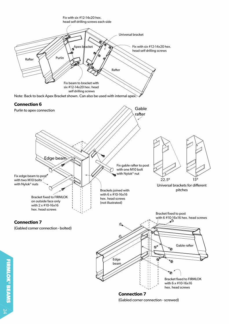
firm
lok
® bea
ms
24
Bracket fixed to FIRMLOKon outside face only with 2 x #10-16x16 hex. head screws
Brackets joined withwith 6 x #10-16x16 hex. head screws(not illustrated)
Fix edge beam to post with two M10 bolts with Nylok® nuts
Fix gable ra�er to post with one M10 bolt with Nylok® nut
Gable ra�er
Edge beam
Connection 6Purlin to apex connection
Connection 7(Gabled corner connection - bolted)
Connection 7(Gabled corner connection - screwed)
Apex bracket
Universal bracket
Fix with six #12-14x20 hex. head self drilling screws each side
Fix with six #12-14x20 hex. head self drilling screws
Ra�er
PurlinRa�er
Fix beam to bracket with six #12-14x20 hex. head
self drilling screwsNote: Back to back Apex Bracket shown. Can also be used with internal apex.
Bracket fixed to post with 6 #10-16x16 hex. head screws
Bracket fixed to FIRMLOKwith 6 x #10-16x16 hex. head screws
Edge beam
Gable ra�er
Universal brackets for different pitches
22.5º 15º

fir
mlo
k®
bea
ms
25
Connection 8(Intermediate gable connection -twin rafter with post)
Connection 9(Bolted intermediate gable connection - with post)
Connection 9(Screwed intermediate gable connection - with post)
Bracket fixed to gable ra�er on outside facewith 3 x #10-16x16hex. head screws
Brackets connected to ra�er on top inside face with 1 x #10-16x16 hex. head screw
Fix edge beam to post with two M10 bolts with Nylok®
nuts. Fix gable ra�er to intermediatepost with one M10 bolt with Nylok® nut.
Edge beam
Gable ra�er
Gable ra�er
Post
Bracket fixed to gablera�er on outside face only with 2 x #10-16x16hex. head screws
Brackets joined to edge beamwith 6 x #10-16x16 hex. head screws(not illustrated)
Fix ra�er to intermediate post with two M10 bolts with Nylok® nuts
Fix gable ra�er to intermediate post with one M10 bolt with Nylok® nut
Edge beam
Bracket fixed to gable ra�er with 6 x #10-16x16 hex. head screws
Brackets connected to intermediate post with 6 x #10-16x16 hex. head screws (not illustrated)
Fix edge beam to post with two M10 bolts with Nylok®
nuts. Bolts will pass through universal bracket.
Edge beam
Gable ra�er

firm
lok
® bea
ms
26
Connection 10Gable with collar tie - Apex and collar tie connection
Collar tie & brackets
Gable Ra�er
L
0.5L
0.3 L
VIEW 'X'Drill 2 holes 13mm dia.
for M12 bolts
50 mm
50 mm
X
X
2 off M12 x 30mmhex. head bolts andnuts with 3mm thicksquare washers underbolt heads and nuts
Ra�ers musttouch brackets here
12 x #10-16x16 screws(3 per ra�er per side)
90º
Collar tie fixed to bracketwith 6 x #10-16x16hex. head screws
Collar tie fixed to gable ra�er with 8 x #10-16x16 hex. head screws
Gable ra�er
Collar tie bracket
Collar tie
Apex details
Typical gable ra�er with collar tie
Collar tie details
==

fir
mlo
k®
bea
ms
27
Connection 11Gable without collar tie - internal apex connection
lysaghT firMlok apex brackets
for each bracket use:
• 24 x 12 -14 x 20 screws for wind classifications
On all 4 faces of bracket:For wind classificationsN1 (W28) use 5 screws
N2 (W33) & N3 (W41) use 6 screws
Place fasteners incentre at recess
Screws at 20mm centres
Apex bracket is availablefor pitches 15° and 22.5°
FIRMLOK must be mitred

firm
lok
® bea
ms
28
www.lysaght.comTechnical enquiries: [email protected] or call 1800 641417LySAGhT®, fIrMLok®, CoLorBoND® & ZINCALUME® are registered trademarks of BlueScope Steel Limited, ABN 16 000 011 058. Bulb-tite® is a registered trademark of ITW Buildex Pty Ltd. The LySAGhT ® range of products is exclusively made by or for BlueScope Steel Limited trading as Lysaght. PM 1000 20/8/14
Product Descriptions
All descriptions, specifications, illustrations, drawings, data, dimensions and weights contained in this catalogue, all technical literature and websites containing information from LySAGhT are approximations only.
They are intended by Lysaght to be a general description for information and identification purposes and do not create a sale by description. Lysaght reserves the right at any time to:
(a) supply Goods with such minor modifications from its drawings and specifications as it sees fit; and
(b) alter specifications shown in its promotional literature to reflect changes made after the date of such publication.
Disclaimer, warranties and limitation of liability
This publication is intended to be an aid for all trades and professionals involved with specifying and installing LySAGhT products and not to be a substitute for professional judgement.
Terms and conditions of sale available at local Lysaght sales offices.
Except to the extent to which liability may not lawfully be excluded or limited, BlueScope Steel Limited will not be under or incur any liability to you for any direct or indirect loss or damage (including, without limitation, consequential loss or damage such as loss of profit or anticipated profit, loss of use, damage to goodwill and loss due to delay) however caused (including, without limitation, breach of contract, negligence and/or breach of statute), which you may suffer or incur in connection with this publication.
© Copyright BlueScope Steel Limited 20 August, 2014
9 3 2 0 0 7 5 0 7 8 0 8 9


