
©2007 McQuay International +1 (800) 432-1342 www.mcquay.com
A Global Leader in System Solutions for Air Conditioning, Heating, Ventilating and Refrigeration.
Products manufactured in an ISO certified facility.This document contains the most current product information as of this printing.For the most up-to-date product information, please go to www.mcquay.com.
AP-5MDS-08All Product Catalogue
R410A Multi Digital Scroll Solution
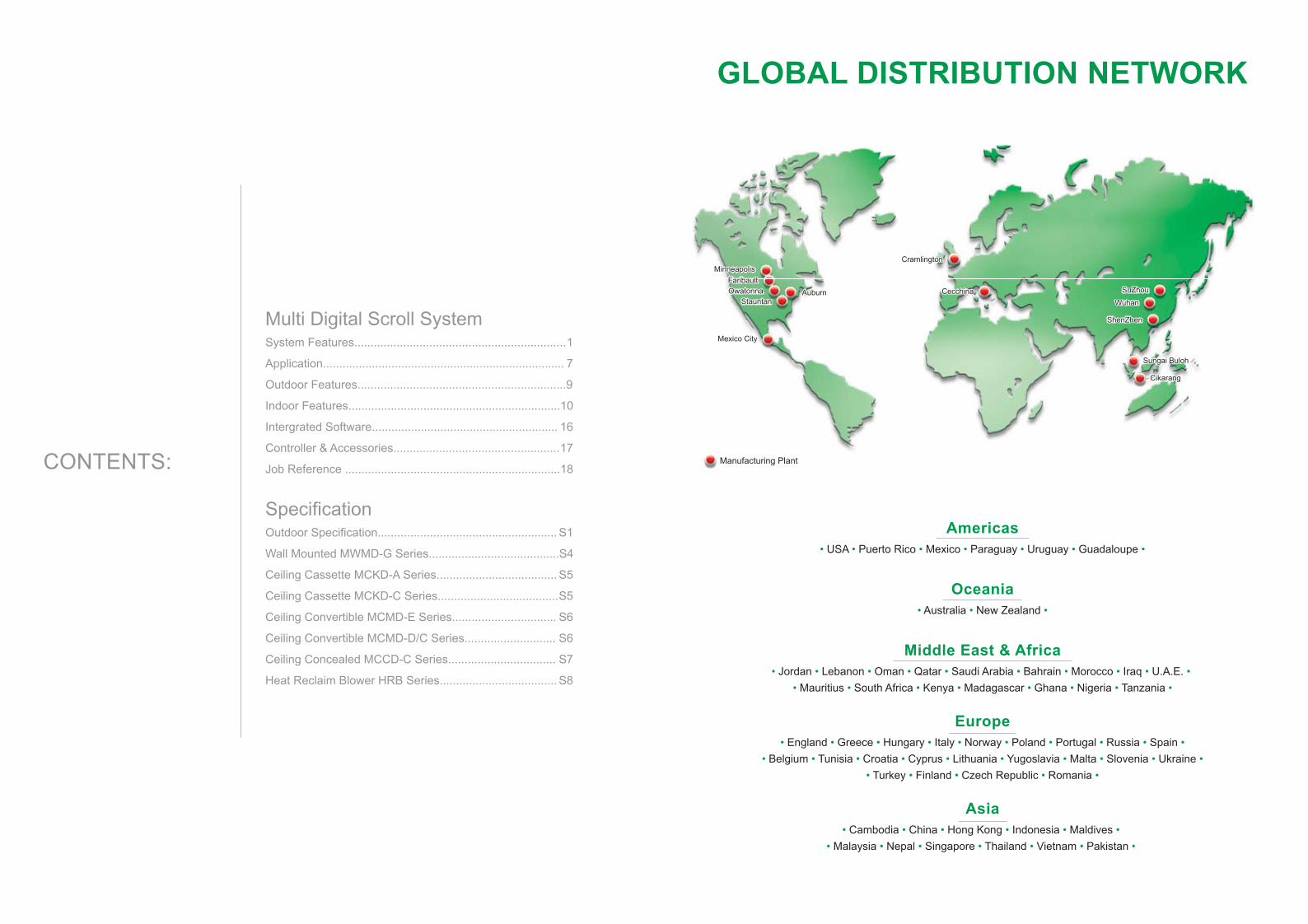
MinneapolisMinneapolis
FaribaultFaribaultOwatonnaOwatonna
StauntanStauntan
Mexico CityMexico City
AuburnAuburn
CramlingtonCramlington
CecchinaCecchina SuZhouSuZhou
WuhanWuhan
ShenZhenShenZhen
Sungai BulohSungai Buloh
CikarangCikarang
Manufacturing Plant
GLOBAL DISTRIBUTION NETWORK
Americas• USA • Puerto Rico • Mexico • Paraguay • Uruguay • Guadaloupe •
Oceania• Australia • New Zealand •
Middle East & Africa• Jordan • Lebanon • Oman • Qatar • Saudi Arabia • Bahrain • Morocco • Iraq • U.A.E. •
• Mauritius • South Africa • Kenya • Madagascar • Ghana • Nigeria • Tanzania •
Europe• England • Greece • Hungary • Italy • Norway • Poland • Portugal • Russia • Spain •
• Belgium • Tunisia • Croatia • Cyprus • Lithuania • Yugoslavia • Malta • Slovenia • Ukraine •
• Turkey • Finland • Czech Republic • Romania •
Asia• Cambodia • China • Hong Kong • Indonesia • Maldives •
• Malaysia • Nepal • Singapore • Thailand • Vietnam • Pakistan •
CONTENTS:
Multi Digital Scroll System
System Features................................................................. 1
Application.......................................................................... 7
Outdoor Features................................................................9
Indoor Features................................................................. 10
Intergrated Software......................................................... 16
Controller & Accessories................................................... 17
Job Reference .................................................................. 18
Specification Outdoor Specification....................................................... S1
Wall Mounted MWMD-G Series........................................ S4
Ceiling Cassette MCKD-A Series..................................... S5
Ceiling Cassette MCKD-C Series..................................... S5
Ceiling Convertible MCMD-E Series................................ S6
Ceiling Convertible MCMD-D/C Series............................ S6
Ceiling Concealed MCCD-C Series................................. S7
Heat Reclaim Blower HRB Series.................................... S8
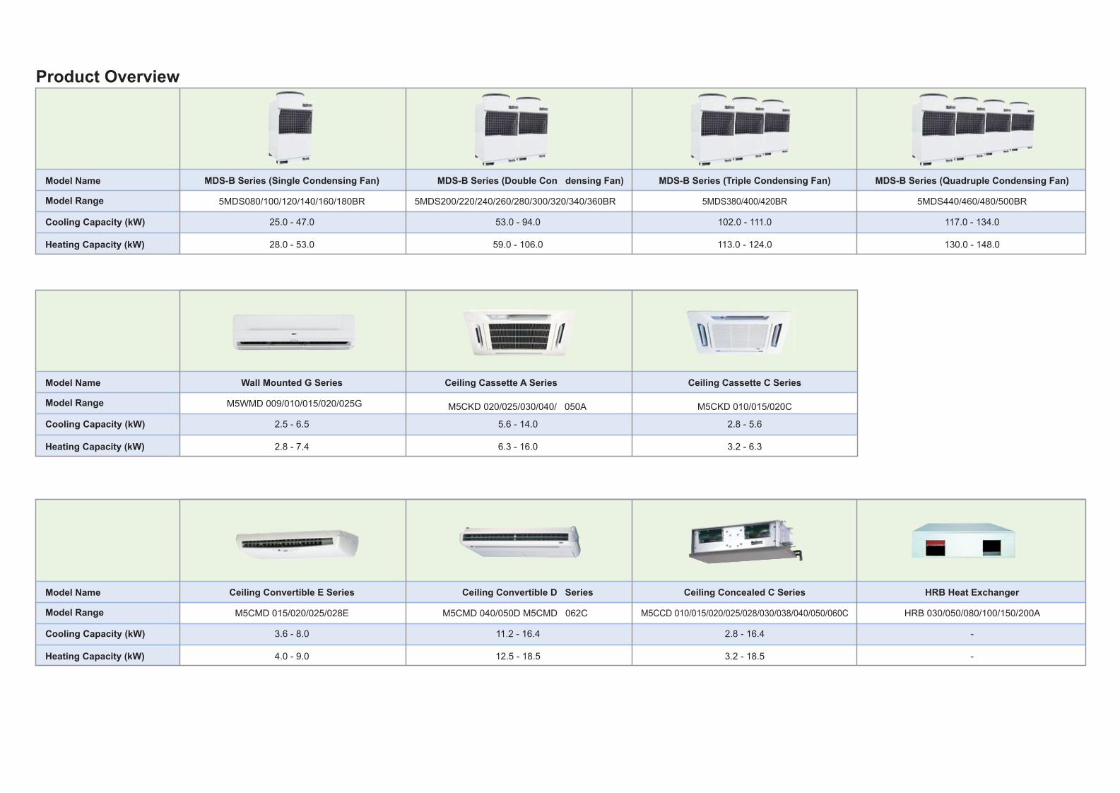
Product Overview
Model Range
Model Name
Cooling Capacity (kW)
Heating Capacity (kW)
Wall Mounted G Series
2.5 - 6.5
M5WMD 009/010/015/020/025G
2.8 - 7.4
Ceiling Cassette A Series
5.6 - 14.0
M5CKD 020/025/030/040/ 050A
6.3 - 16.0
Ceiling Cassette C Series
2.8 - 5.6
M5CKD 010/015/020C
3.2 - 6.3
Model Range
Model Name
Cooling Capacity (kW)
Heating Capacity (kW)
Ceiling Convertible E Series
3.6 - 8.0
M5CMD 015/020/025/028E
4.0 - 9.0
Ceiling Convertible D Series
11.2 - 16.4
M5CMD 040/050D M5CMD 062C
12.5 - 18.5
Ceiling Concealed C Series
2.8 - 16.4
M5CCD 010/015/020/025/028/030/038/040/050/060C
3.2 - 18.5
HRB Heat Exchanger
-
HRB 030/050/080/100/150/200A
-
Model Range
Model Name
Cooling Capacity (kW)
Heating Capacity (kW)
MDS-B Series (Single Condensing Fan)
25.0 - 47.0
5MDS080/100/120/140/160/180BR
28.0 - 53.0
MDS-B Series (Double Con densing Fan)
53.0 - 94.0
5MDS200/220/240/260/280/300/320/340/360BR
59.0 - 106.0
MDS-B Series (Triple Condensing Fan)
102.0 - 111.0
5MDS380/400/420BR
113.0 - 124.0
MDS-B Series (Quadruple Condensing Fan)
117.0 - 134.0
5MDS440/460/480/500BR
130.0 - 148.0
1
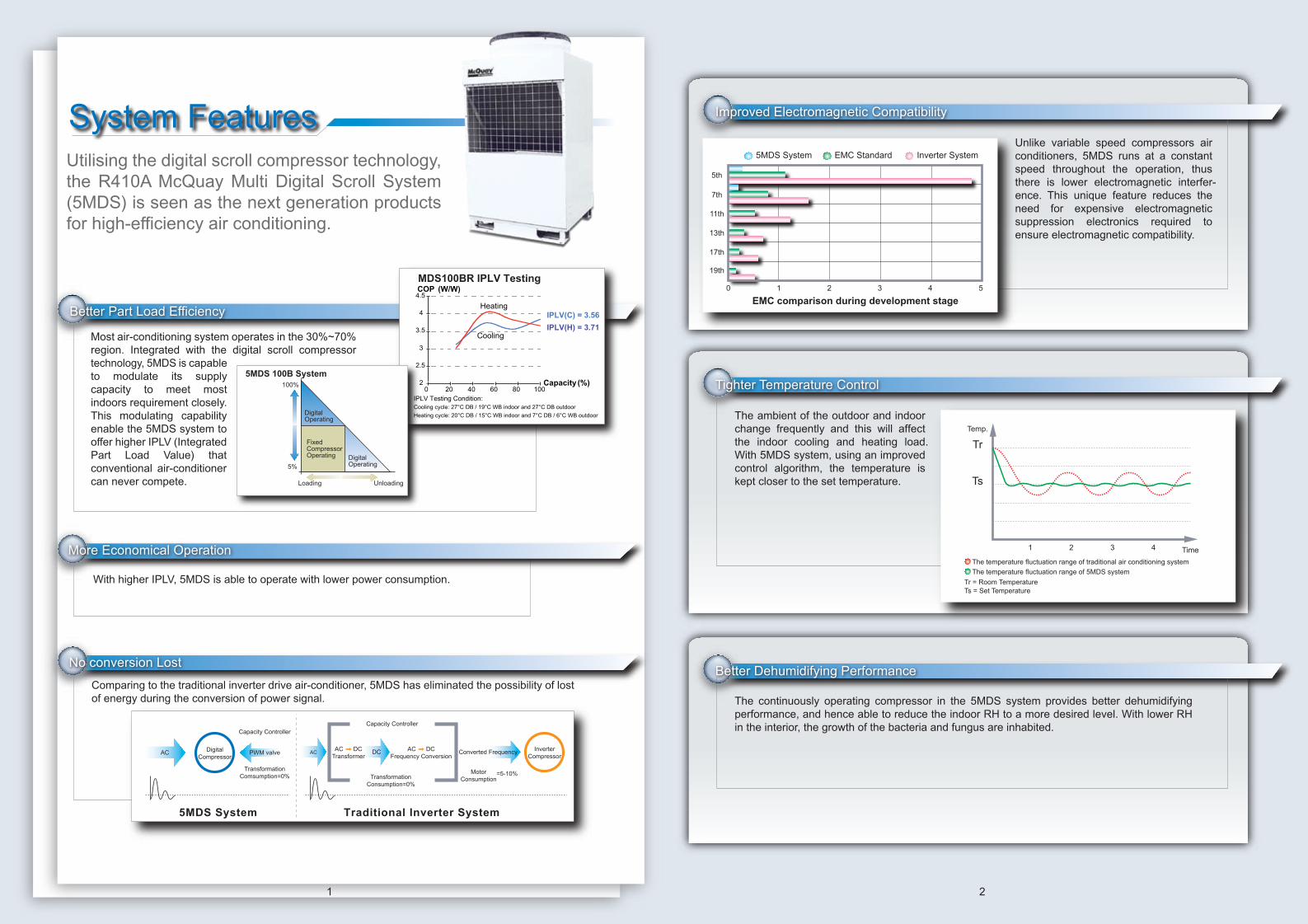
Better Part Load Efficiency
Most air-conditioning system operates in the 30%~70% region. Integrated with the digital scroll compressor technology, 5MDS is capable to modulate its supply capacity to meet most indoors requirement closely. This modulating capability enable the 5MDS system to offer higher IPLV (Integrated Part Load Value) that conventional air-conditioner can never compete.
Comparing to the traditional inverter drive air-conditioner, 5MDS has eliminated the possibility of lost of energy during the conversion of power signal.
No conversion Lost
AC Converted Frequency InverterCompressor
Capacity Controller
TransformationConsumption=0%
MotorConsumption
=5-10%
DCAC DCTransformer
AC DCFrequency Conversion
DigitalCompressor
AC PWM valve
Capacity Controller
TransformationComsumption=0%
Traditional Inverter System5MDS System
Utilising the digital scroll compressor technology, the R410A McQuay Multi Digital Scroll System (5MDS) is seen as the next generation products for high-efficiency air conditioning.
2
System Features
The ambient of the outdoor and indoor change frequently and this will affect the indoor cooling and heating load. With 5MDS system, using an improved control algorithm, the temperature is kept closer to the set temperature.
Better Dehumidifying Performance
The continuously operating compressor in the 5MDS system provides better dehumidifying performance, and hence able to reduce the indoor RH to a more desired level. With lower RH in the interior, the growth of the bacteria and fungus are inhabited.
Improved Electromagnetic Compatibility
Unlike variable speed compressors air conditioners, 5MDS runs at a constant speed throughout the operation, thus there is lower electromagnetic interfer-ence. This unique feature reduces the need for expensive electromagnetic suppression electronics required to ensure electromagnetic compatibility.
5th
7th
11th
13th
17th
19th
0 1 2 3 4 5
5MDS System EMC Standard Inverter System
EMC comparison during development stage
Temp.
Time1 2 3 4
Tr
Ts
The temperature fluctuation range of traditional air conditioning system
The temperature fluctuation range of 5MDS system
Tr = Room TemperatureTs = Set Temperature
Tighter Temperature Control
With higher IPLV, 5MDS is able to operate with lower power consumption.
More Economical Operation
MDS100BR IPLV Testing
2
2.5
3
3.5
4
4.5
0 20 40 60 80 100
IPLV(C) = 3.56
IPLV(H) = 3.71
Capacity (%)
Cooling
Heating
COP (W/W)
IPLV Testing Condition:Cooling cycle: 27°C DB / 19°C WB indoor and 27°C DB outdoor
Heating cycle: 20°C DB / 15°C WB indoor and 7°C DB / 6°C WB outdoor
5MDS 100B System100%
5%
FixedCompressorOperating
DigitalOperating
DigitalOperating
Loading Unloading

3 4
Wider Operating Range
5MDS system undergo rigorous test to ensure that the system can operate within -15ºC to 48ºC.
The improved heat-exchanger combining with the better efficiency compressor promotes faster exchange between refrigerant and air, ensuring set temperature to be achieved faster compared to traditional air-conditioning system.
Long Piping Design For Flexibility
Piping length between outdoor and indoor unit can be extended up to 175 meters. The height between outdoor unit and indoor unit can be extended up to 50 meters. The height difference between indoor units can be as high as 15 meters. This greatly reduces constraint and offers more flexibility in system design.
Better Place Utilisation
5MDS uses the single outdoor multiple indoors combina-tion. This concept has greatly reduced the outdoor units and enhances flexibility during installation.
Better Solution
Comparing to conventional chilled water system, 5MDS required far less equipment. Boilers, cooling tower are things in the past with 5MDS. Thus, 5MDS is a better solution for new projects or even retrofit purposes.
Easier Installation
In-house designed piping joints and wiring connection make it possible to install 5MDS system fasterand easier.
t1 t2Time
InitialTemperature
SettingTemperature
Traditional Air Conditioning5MDS System
The 5MDS system operates in a stepless capacity modulation ranging from 10~100%. The modulation will closely match the demand capacity whereby contributing higher IPLV.
Rapid Cooling and Heating Capability
Intelligent Capacity Modulation
Temperature °C
48°CDB
0°CDB
15.5°CWB
-16°CWDB
50
40
30
20
10
0
-10
-20
Cooling C
ycle
Heating Cycle
Height15m
PipingLength175m
Height50m
Conventional ChilledWater System
5MDS System
Only a common 2-core, screen cable wire is required to enable communication between outdoor and indoors.
The refnet joint is provided by the factory in accordance with different indoor units, which will reduce the work force at site.
5 6
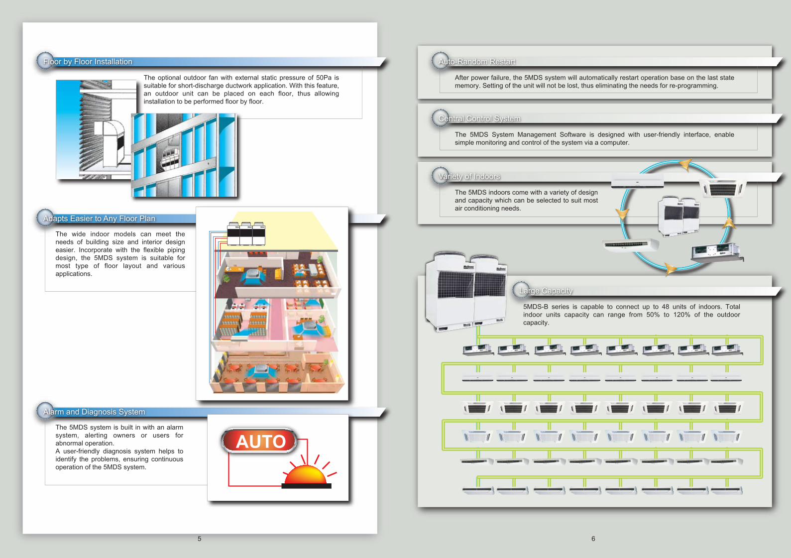
The optional outdoor fan with external static pressure of 50Pa is suitable for short-discharge ductwork application. With this feature, an outdoor unit can be placed on each floor, thus allowing installation to be performed floor by floor.
Floor by Floor Installation
The wide indoor models can meet the needs of building size and interior design easier. Incorporate with the flexible piping design, the 5MDS system is suitable for most type of floor layout and various applications.
Adapts Easier to Any Floor Plan
The 5MDS system is built in with an alarm system, alerting owners or users for abnormal operation.A user-friendly diagnosis system helps to identify the problems, ensuring continuous operation of the 5MDS system.
Alarm and Diagnosis System
AUTO
Auto-Random Restart
Central Control System
The 5MDS System Management Software is designed with user-friendly interface, enable simple monitoring and control of the system via a computer.
After power failure, the 5MDS system will automatically restart operation base on the last state memory. Setting of the unit will not be lost, thus eliminating the needs for re-programming.
The 5MDS indoors come with a variety of design and capacity which can be selected to suit most air conditioning needs.
Variety of Indoors
5MDS-B series is capable to connect up to 48 units of indoors. Total indoor units capacity can range from 50% to 120% of the outdoor capacity.
Large Capacity
7 8
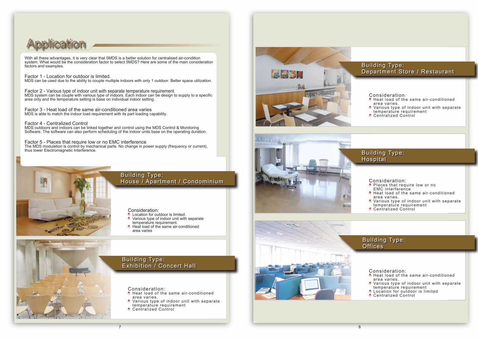
ApplicationWith all these advantages, it is very clear that 5MDS is a better solution for centralised air-condition system. What would be the consideration factor to select 5MDS? Here are some of the main consideration factors and examples.
Factor 1 - Location for outdoor is limited. MDS can be used due to the ability to couple multiple indoors with only 1 outdoor. Better space utilization.
Factor 2 - Various type of indoor unit with separate temperature requirementMDS system can be couple with various type of indoors. Each indoor can be design to supply to a specific area only and the temperature setting is base on individual indoor setting.
Factor 3 - Heat load of the same air-conditioned area variesMDS is able to match the indoor load requirement with its part loading capability.
Factor 4 - Centralized ControlMDS outdoors and indoors can be linked together and control using the MDS Control & Monitoring Software. The software can also perform scheduling of the indoor units base on the operating duration.
Factor 5 - Places that require low or no EMC interferenceThe MDS modulation is control by mechanical parts. No change in power supply (frequency or current), thus lower Electromagnetic Interference.
Consideration:• Location for outdoor is limited.• Various type of indoor unit with separate temperature requirement.• Heat load of the same air-conditioned area varies
Bui ld ing Type: House / Apartment / Condominium
Bui ld ing Type: Exhibi t ion / Concert Hal l
Considerat ion:• Heat load of the same air-condi t ioned area var ies.• Var ious type of indoor uni t wi th separate temperature requirement • Central ized Control
Bui ld ing Type: Department Store / Restaurant
Bui ld ing Type: Hospi ta l
Bui ld ing Type:Off ices
Considerat ion:• Places that require low or no EMC interference • Heat load of the same air-condi t ioned area var ies.• Var ious type of indoor uni t wi th separate temperature requirement • Central ized Control
Considerat ion:• Heat load of the same air-condi t ioned area var ies.• Var ious type of indoor uni t wi th separate temperature requirement • Locat ion for outdoor is l imi ted• Central ized Control
Considerat ion:• Heat load of the same air-condi t ioned area var ies.• Var ious type of indoor uni t wi th separate temperature requirement • Central ized Control
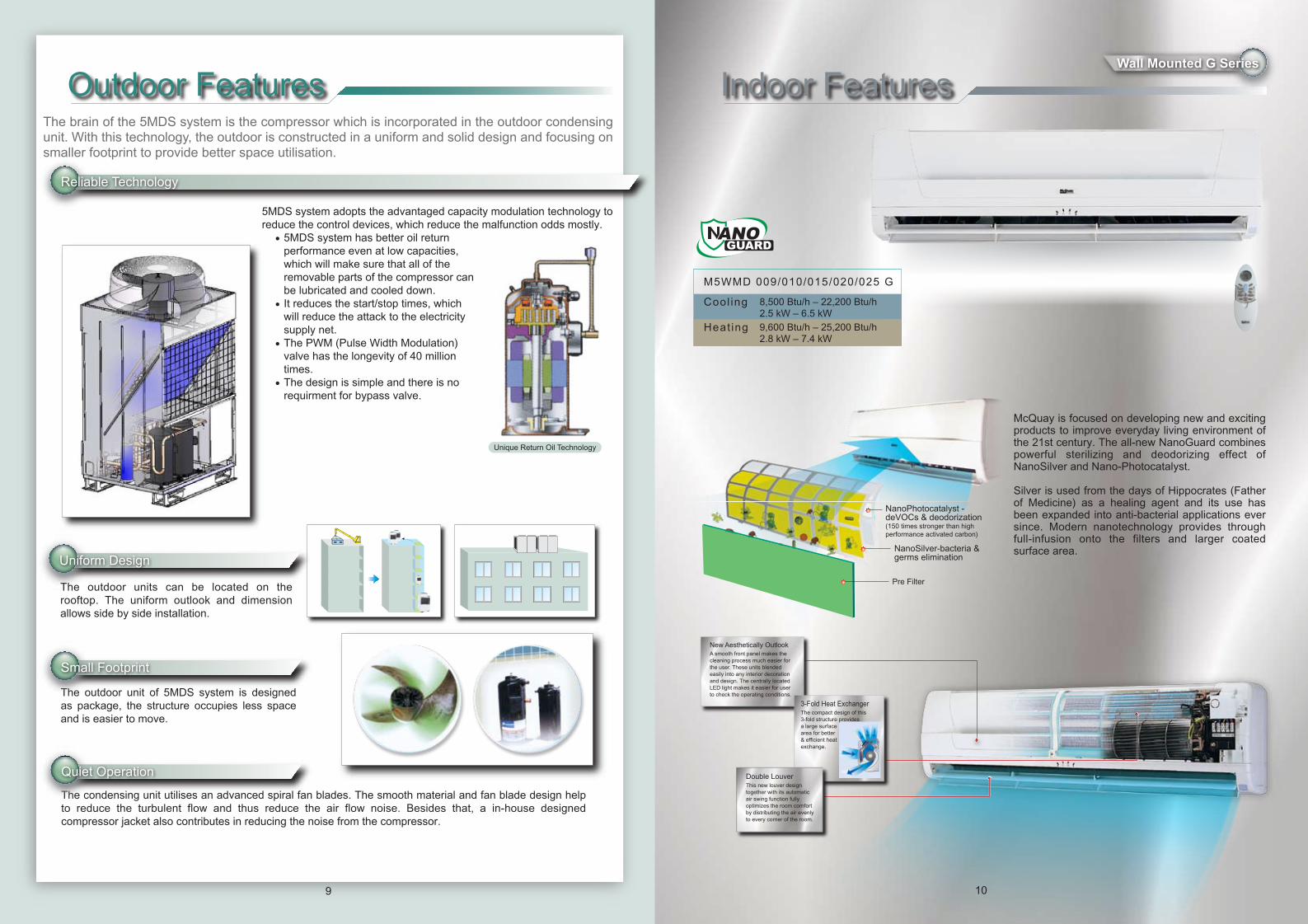
The outdoor unit of 5MDS system is designed as package, the structure occupies less space and is easier to move.
The condensing unit utilises an advanced spiral fan blades. The smooth material and fan blade design help to reduce the turbulent flow and thus reduce the air flow noise. Besides that, a in-house designed compressor jacket also contributes in reducing the noise from the compressor.
Unique Return Oil Technology
9
NanoPhotocatalyst -deVOCs & deodorization(150 times stronger than highperformance activated carbon)
NanoSilver-bacteria &germs elimination
Pre Filter
10
M5WMD 009/010/015/020/025 G
Cool ing 8,500 Btu/h – 22,200 Btu/h2.5 kW – 6.5 kW
Heat ing 9,600 Btu/h – 25,200 Btu/h2.8 kW – 7.4 kW
Outdoor Features Indoor FeaturesThe brain of the 5MDS system is the compressor which is incorporated in the outdoor condensing unit. With this technology, the outdoor is constructed in a uniform and solid design and focusing on smaller footprint to provide better space utilisation.
5MDS system adopts the advantaged capacity modulation technology to reduce the control devices, which reduce the malfunction odds mostly. • 5MDS system has better oil return performance even at low capacities, which will make sure that all of the removable parts of the compressor can be lubricated and cooled down. • It reduces the start/stop times, which will reduce the attack to the electricity supply net. • The PWM (Pulse Width Modulation) valve has the longevity of 40 million times. • The design is simple and there is no requirment for bypass valve.
Reliable Technology
Small Footprint
Uniform Design
Quiet Operation
The outdoor units can be located on the rooftop. The uniform outlook and dimension allows side by side installation.
Wall Mounted G Series
New Aesthetically Outlook A smooth front panel makes the cleaning process much easier for the user. These units blended easily into any interior decoration and design. The centrally located LED light makes it easier for user to check the operating conditions.
3-Fold Heat Exchanger The compact design of this 3-fold structure providesa large surfacearea for better& efficient heatexchange.
Double Louver This new louver design together with its automatic air swing function fully optimizes the room comfort by distributing the air evenly to every corner of the room.
McQuay is focused on developing new and exciting products to improve everyday living environment of the 21st century. The all-new NanoGuard combines powerful sterilizing and deodorizing effect of NanoSilver and Nano-Photocatalyst.
Silver is used from the days of Hippocrates (Father of Medicine) as a healing agent and its use has been expanded into anti-bacterial applications ever since. Modern nanotechnology provides through full-infusion onto the filters and larger coated surface area.

11
M5CKD 010/015/020 CM5CKD 020/025/030/040/050 ACool ing 9,600 Btu/h – 47,800 Btu/h
2.8 kW – 14.0 kW
Heat ing 10,900 Btu/h – 54,600 Btu/h3.2 kW – 16.0 kW
Ceiling Convertible E Series
12
M5CMD 015/020/025/028 E
Cool ing 12,300 Btu/h – 27,300 Btu/h3.6 kW – 8.0 kW
Heat ing 13,600 Btu/h – 30,700 Btu/h4.0 kW – 9.0 kW
The washable filter can be easily access by just pulling down the intake grill. During servicing or repairing, only the bottom panel need to be remove in order to access.
• Fan Motor• Blower• Wiring Connection
• Control Box• Piping Connection
Ceiling Cassette A and C Series Ceiling Convertible E Series
700mm
Wall bracket supplied as optional item
700mm
Sty l i sh And S l im Pane l
The slim panel can be blended easily into most interior decoration and design.
Ce i l ing and F loor Ins ta l la t ion Opt ion
The MCM is designed with the option to install either below the ceiling or mounted at low wall position to suit most interior design requirement.
F lex ib le Ins ta l la t ion
The unit is designed to work with high pressure head drain pump (optional). Thus offering flexibility for installation on condensate drain pipe. The drain pump comes with a high head and is incorporate with the float switch as safety protection.
Bet te r Serv iceab i l i t y
4 Way A i r D ischarge And A i r Swing
It comes with 4 way air discharge and air swing function to ensure better air distribution and circulation in the room.
Bu i l t - In H igh Head Dra in Pump
The unit comes with a built-in high head drain pump 700mm head. A safety float is incorporated in the drain pump to monitor its water level.
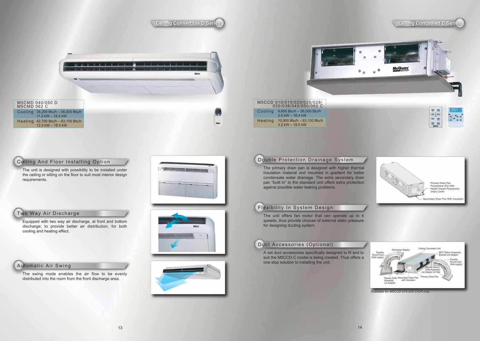
Ceiling Convertible D Series Ceiling Concealed C Series
Cei l ing And F loor Ins ta l l ing Opt ion
The unit is designed with possibility to be installed under the ceiling or sitting on the floor to suit most interior design requirements.
Doub le Pro tec t ion Dra inage Sys tem
The primary drain pan is designed with higher thermal insulation material and moulded in gradient for better condensate water drainage. The extra secondary drain pan “built in” to the standard unit offers extra protection against possible water leaking problems.
F lex ib i l i t y In Sys tem Des ign
The unit offers fan motor that can operate up to 4 speeds, thus provide choices of external static pressure for designing ducting system.
Duct Accessor ies (Opt iona l )
A set duct accessories specifically designed to fit and to suit the M5CCD-C model is being created. Thus offers a one stop solution to installing the unit.
Two Way A i r D ischarge
Equipped with two way air discharge, at front and bottom discharge; to provide better air distribution, for both cooling and heating effect.
Au tomat ic A i r Swing
The swing mode enables the air flow to be evenly distributed into the room from the front discharge area.
13
M5CMD 040/050 DM5CMD 062 CCool ing 38,200 Btu/h – 56,000 Btu/h
11.2 kW – 16.4 kW
Heat ing 42,700 Btu/h – 63,100 Btu/h12.5 kW – 18.5 kW
Available for M5CCD 010-025 C/CR only.
14
M5CCD 010/015/020/025/028/ 030/038/040/050/060 CCool ing 9,600 Btu/h – 56,000 Btu/h
2.8 kW – 16.4 kW
Heat ing 10,900 Btu/h – 63,100 Btu/h3.2 kW – 18.5 kW
Primary Drain PanPolysterene (Ps) With Height Impact Polystyrene (Hips) Cover
Secondary Drain Pan With Insulation
Discharge Adaptor
Square GrilleAssembly c/w Adaptor
Secondary Drain Pan with Insulation
Primary Drain Pan
Square Return Grille Assembly
c/w Adaptor & Filter
FlexibleRound Duct(field supply)
Ceiling Concealed Unit
MCC Return AssemblyBracket c/w Adaptor
FlexibleRound Duct
(field supply)
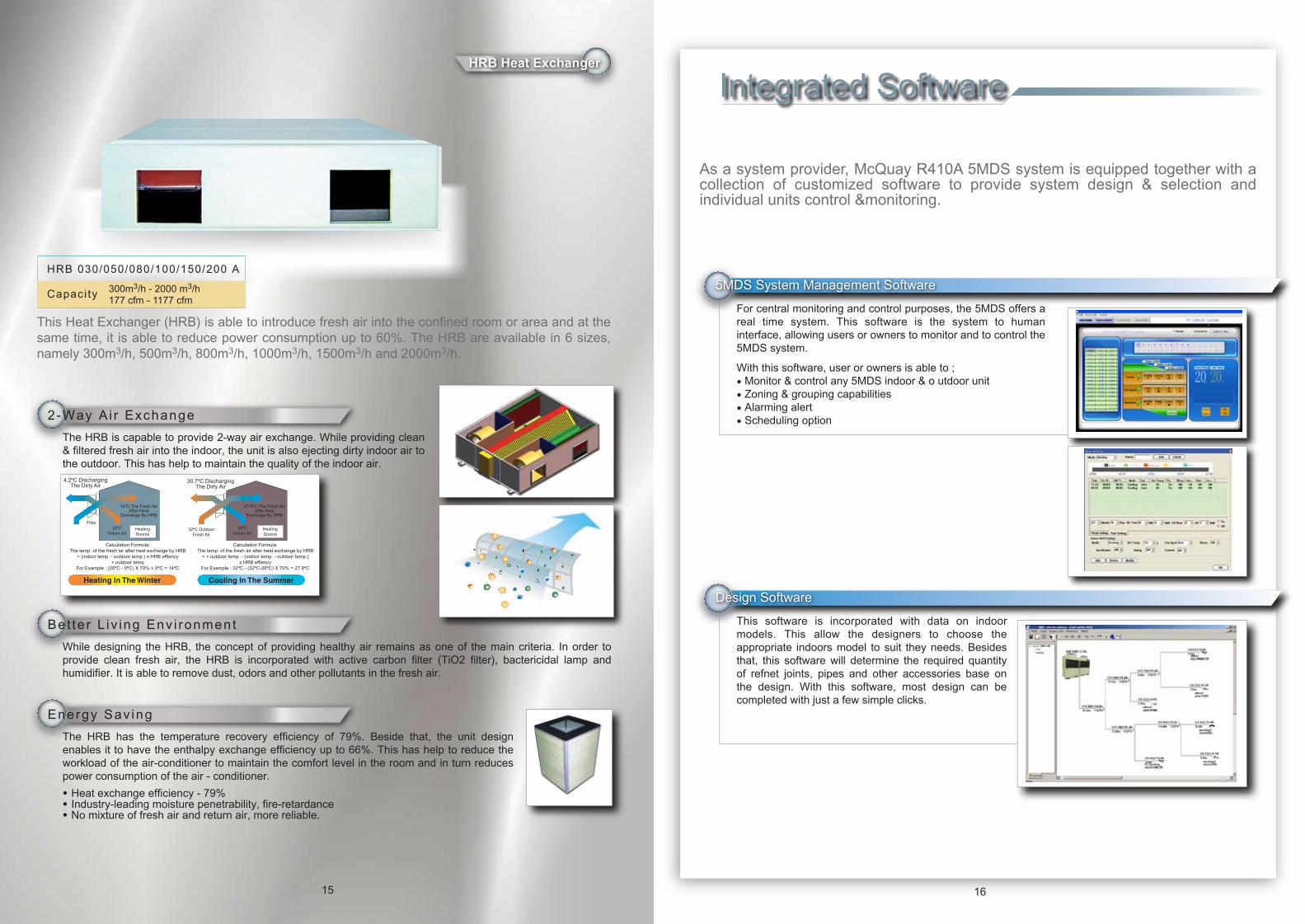
5MDS System Management Software
2-Way A i r Exchange
The HRB is capable to provide 2-way air exchange. While providing clean & filtered fresh air into the indoor, the unit is also ejecting dirty indoor air to the outdoor. This has help to maintain the quality of the indoor air.
Be t te r L iv ing Env i ronment
While designing the HRB, the concept of providing healthy air remains as one of the main criteria. In order to provide clean fresh air, the HRB is incorporated with active carbon filter (TiO2 filter), bactericidal lamp and humidifier. It is able to remove dust, odors and other pollutants in the fresh air.
Energy Sav ing
The HRB has the temperature recovery efficiency of 79%. Beside that, the unit design enables it to have the enthalpy exchange efficiency up to 66%. This has help to reduce the workload of the air-conditioner to maintain the comfort level in the room and in turn reduces power consumption of the air - conditioner.
• Heat exchange efficiency - 79%• Industry-leading moisture penetrability, fire-retardance• No mixture of fresh air and return air, more reliable.
This Heat Exchanger (HRB) is able to introduce fresh air into the confined room or area and at the same time, it is able to reduce power consumption up to 60%. The HRB are available in 6 sizes, namely 300m3/h, 500m3/h, 800m3/h, 1000m3/h, 1500m3/h and 2000m3/h.
4.2ºC DischargingThe Dirty Air
Filter
14ºC The Fresh AirAfter Heat
Exchange By HRB
20ºCIndoor Air
HeatingSource
Calculation Formula:The temp. of the fresh air after heat exchange by HRB
= (indoor temp. - outdoor temp.) x HRB effiency+ outdoor temp
For Example : (20ºC - 0ºC) X 70% + 0ºC = 14ºC
30.7ºC DischargingThe Dirty Air
32ºC OutdoorFresh Air
27.8ºC The Fresh AirAfter Heat
Exchange By HRB
26ºCIndoor Air
HeatingSource
Calculation Formula:The temp. of the fresh air after heat exchange by HRB
= + outdoor temp. - (indoor temp. - outdoor temp.)x HRB effiency
For Example : 32ºC - (32ºC-26ºC) X 70% = 27.8ºC
Heating In The Winter Cooling In The Summer
HRB 030/050/080/100/150/200 A
Capaci ty 300m3/h - 2000 m3/h177 cfm - 1177 cfm
15 16
As a system provider, McQuay R410A 5MDS system is equipped together with a collection of customized software to provide system design & selection and individual units control &monitoring.
For central monitoring and control purposes, the 5MDS offers a real time system. This software is the system to human interface, allowing users or owners to monitor and to control the 5MDS system.
With this software, user or owners is able to ;• Monitor & control any 5MDS indoor & o utdoor unit• Zoning & grouping capabilities• Alarming alert• Scheduling option
Design Software
This software is incorporated with data on indoor models. This allow the designers to choose the appropriate indoors model to suit they needs. Besides that, this software will determine the required quantity of refnet joints, pipes and other accessories base on the design. With this software, most design can be completed with just a few simple clicks.
HRB Heat Exchanger
Integrated Software
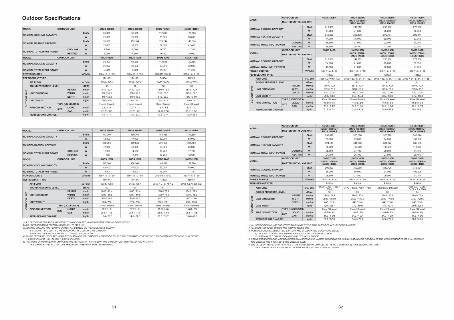
MDS systems has proven to be reliable and a system of choice. Many projects, whether government or privately own premises had chosen MDS as their comfort provider:
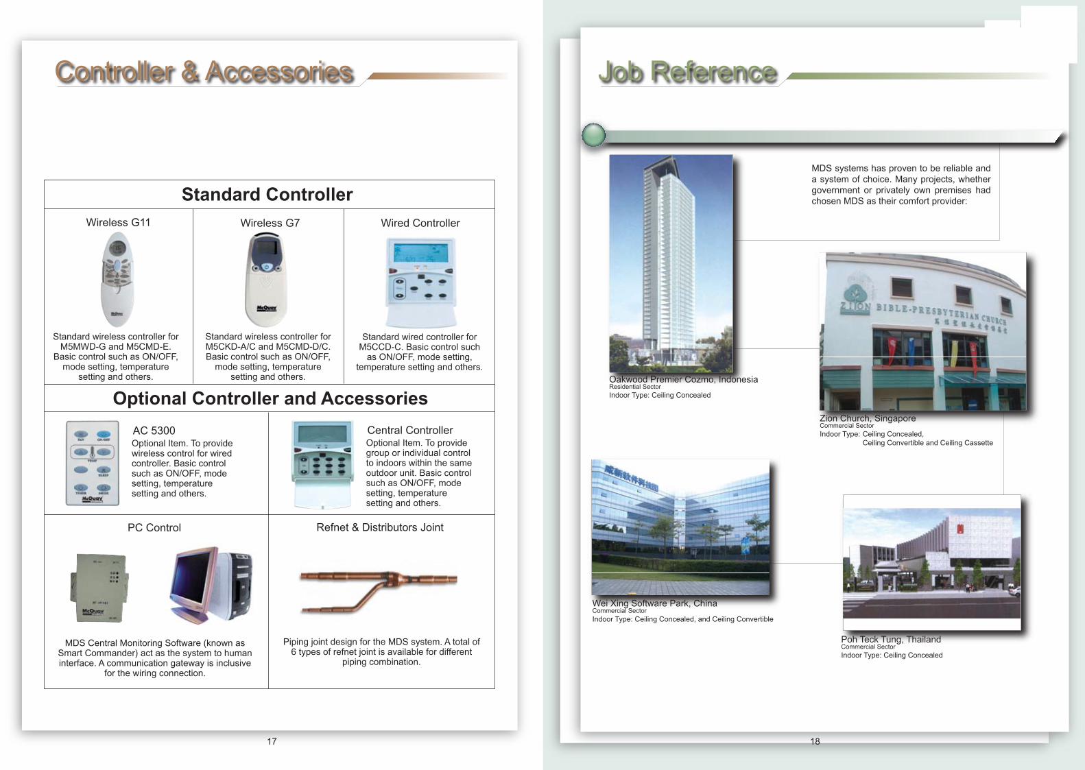
Controller & Accessories
Oakwood Premier Cozmo, IndonesiaResidential SectorIndoor Type: Ceiling Concealed
Zion Church, Singapore Commercial SectorIndoor Type: Ceiling Concealed, Ceiling Convertible and Ceiling Cassette
Wei Xing Software Park, China Commercial SectorIndoor Type: Ceiling Concealed, and Ceiling Convertible
Poh Teck Tung, Thailand Commercial SectorIndoor Type: Ceiling Concealed
1817
Wired Controller
Standard Controller
Optional Controller and Accessories
Wireless G11 Wireless G7
Standard wireless controller for M5MWD-G and M5CMD-E.
Basic control such as ON/OFF, mode setting, temperature
setting and others.
Standard wireless controller for M5CKD-A/C and M5CMD-D/C. Basic control such as ON/OFF,
mode setting, temperature setting and others.
Standard wired controller for M5CCD-C. Basic control such
as ON/OFF, mode setting, temperature setting and others.
Optional Item. To providewireless control for wiredcontroller. Basic controlsuch as ON/OFF, modesetting, temperaturesetting and others.
AC 5300Optional Item. To providegroup or individual control to indoors within the same outdoor unit. Basic control such as ON/OFF, mode setting, temperature setting and others.
Central Controller
PC Control Refnet & Distributors Joint
MDS Central Monitoring Software (known as Smart Commander) act as the system to human interface. A communication gateway is inclusive
for the wiring connection.
Piping joint design for the MDS system. A total of 6 types of refnet joint is available for different
piping combination.
Job Reference
S1 S2
1
2
3
4
5
6
7
8
9
10
11
12
13
14
15
16
17
18
19
20
21
22
23
24
25
26
27
28
29
30
31
32
33
34
35
36
37
38
A B C D E F G
Specification for AMDS
AMDS080BR AMDS100BR
Btu/h 83,594 95,536
W 24,500 28,000
Btu/h 88,712 102,360
W 26,000 30,000
W 7,500 8,500
W 7,200 8,300
AMDS080B AMDS100B
Btu/h 83,594 95,536
W 24,500 28,000
W 7,500 8,500
V/Ph/Hz 380/3/50 380/3/50
R22 R22
HI-FAN l/s / cfm 3194/6768 3194/6768
LOW-FAN l/s / cfm 1528/3237 1528/3237
dB(A) 62 64
HEIGHT mm/in 1840/72.4 1840/72.4
WIDTH mm/in 990/39.0 990/39.0
DEPTH mm/in 840/33.0 840/33.0
kg/lb 275/606 385/628
Flare/Brazed Flare/Brazed
LIQUID mm/in 12.7/0.5 12.7/0.5
GAS mm/in 28.6/1.125 28.6/1.125
AMDS180BR AMDS200BR
Btu/h 162,070 170,600
W 47,500 50,000
Btu/h 170,600 180,836
W 50,000 53,000
W 14,100 15,200
W 13,200 14,700
AMDS180B AMDS200B
Btu/h 162,070 170,600
W 47,500 50,000
W 14,100 15,200
POWER SOURCE
MODEL OUTDOOR UNIT
NOMINAL COOLING CAPACITY
NOMINAL TOTAL INPUT POWER
NOMINAL COOLING CAPACITY
NOMINAL HEATING CAPACITY
NOMINAL TOTAL INPUT POWER (COOLING)
NOMINAL TOTAL INPUT POWER (HEATING)
OUTDOOR UNIT
AIR FLOW
SOUND PRESSURE LEVEL
UNIT WEIGHT
PIPE CONNECTION
MODEL OUTDOOR UNIT
NOMINAL COOLING CAPACITY
NOMINAL TOTAL INPUT POWER
MODEL OUTDOOR UNIT
MODEL OUTDOOR UNIT
NOMINAL COOLING CAPACITY
NOMINAL HEATING CAPACITY
NOMINAL TOTAL INPUT POWER (COOLING)
NOMINAL TOTAL INPUT POWER (HEATING)
SIZE
UNIT DIMENSION
POWER SOURCE
REFRIGERANT TYPE
TYPE (LIQUID/GAS)
Outdoor Specifications
5MDS 080BR 5MDS 100BR 5MDS 120BR 5MDS 140BR
Btu/h 85,300 95,536 112,596 129,656
W 25,000 28,000 33,000 38,000
Btu/h 95,536 109,184 126,244 143,304
W 28,000 32,000 37,000 42,000
COOLING W 7,200 8,000 9,700 11,300
HEATING W 7,000 7,900 9,400 10,900
5MDS 080B 5MDS 100B 5MDS 120B 5MDS 140B
Btu/h 85,300 95,536 112,596 129,656
W 25,000 28,000 33,000 38,000
W 7,200 8,000 9,700 11,300
V/Ph/Hz 380-415 / 3 / 50 380-415 / 3 / 50 380-415 / 3 / 50 380-415 / 3 / 50
R410A R410A R410A R410A
l/s / cfm 3056 / 6474 3056 / 6474 3056 / 6474 3333 / 7063
dB(A) 56 57 60 60
HEIGHT mm/in 1840 / 72.4 1840 / 72.4 1840 / 72.4 1840 / 72.4
WIDTH mm/in 990 / 39.0 990 / 39.0 990 / 39.0 1290 / 50.8
DEPTH mm/in 840 / 33.0 840 / 33.0 840 / 33.0 840 / 33.0
kg/lb 290 / 639 300 / 661 305 / 672 350 / 771
Flare / Brazed Flare / Brazed Flare / Brazed Flare / Brazed
LIQUID mm/in 9.52 / 3/8 12.7 / 1/2 12.7 / 1/2 12.7 / 1/2
GAS mm/in 22.23 / 7/8 22.23 / 7/8 22.23 / 7/8 28.6 / 1 1/8
kg/lb 7.9 / 17.4 10.0 / 22.0 10.6 / 23.4 12.2 / 26.9
5MDS 160BR 5MDS 180BR 5MDS 200BR 5MDS 220BR
Btu/h 143,304 160,364 180,836 197,896
W 42,000 47,000 53,000 58,000
Btu/h 160,364 180,836 201,308 221,780
W 47,000 53,000 59,000 65,000
COOLING W 12,900 14,500 16,200 17,700
HEATING W 11,900 13,800 14,700 16,900
5MDS 160B 5MDS 180B 5MDS 200B 5MDS 220B
Btu/h 143,304 160,364 180,836 197,896
W 42,000 47,000 53,000 58,000
W 12,900 14,500 16,200 17,700
V/Ph/Hz 380-415 / 3 / 50 380-415 / 3 / 50 380-415 / 3 / 50 380-415 / 3 / 50
R410A R410A R410A R410A
l/s / cfm 3333 / 7063 3472 / 7357 3056 X 2 / 6474 X 2 2778 X 2 / 5886 X 2
dB(A) 60 61 61 62
HEIGHT mm/in 1840 / 72.4 1840 / 72.4 1840 / 72.4 1840 / 72.4
WIDTH mm/in 1290 / 50.8 1290 / 50.8 1990 / 78.3 1990 / 78.3
DEPTH mm/in 840 / 33.0 840 / 33.0 840 / 33.0 840 / 33.0
kg/lb 360 / 793 370 / 816 590 / 1301 590 / 1301
Flare / Brazed Flare / Brazed Flare / Brazed Flare / Brazed
LIQUID mm/in 12.7 / 1/2 12.7 / 1/2 15.88 / 5/8 15.88 / 5/8
GAS mm/in 28.6 / 1 1/8 28.6 / 1 1/8 28.6 / 1 1/8 28.6 / 1 1/8
kg/lb 13.4 / 29.5 14.8 / 32.6 18.0 / 39.7 19.6 / 43.2
1) ALL SPECIFICATIONS ARE SUBJECTED TO CHANGE BY THE MANUFACTURER WITHOUT PRIOR NOTICE.2) ALL UNITS ARE BEING TESTED AND COMPLY TO ISO 5151.3) NOMINAL COOLING AND HEATING CAPACITY ARE BASED ON THE CONDITIONS BELOW :
a) COOLING - 27°C DB / 19°C WB INDOOR AND 35°C DB / 24°C WB OUTDOORb) HEATING - 20°C DB INDOOR AND 7°C DB / 6°C WB OUTDOOR
4) SOUND PRESSURE LEVEL ARE MEASURED IN AN ANECHOIC CHAMBER, ACCORDING TO JIS B 8615 STANDARD. POSITION OF THE MEASUREMENT POINT IS 1m IN FRONT. THE MACHINE AND 1.42m ABOVE THE MACHINE BASE.5) THE VALUE OF REFRIGERANT CHARGE IS THE REFRIGERANT CHARGED IN THE OUTDOOR UNIT BEFORE LEAVING FACTORY.
THIS CHARGE DOES NOT INCLUDE THE AMOUNT NEEDED FOR EXTENDED PIPING.
NOMINAL TOTAL INPUT POWER
MODEL OUTDOOR UNIT
REFRIGERANT CHARGE
POWER SOURCE
REFRIGERANT TYPE
SOUND PRESSURE LEVEL
UNIT DIMENSION
MODEL OUTDOOR UNIT
TYPE (LIQUID/GAS)
SIZE
NOMINAL COOLING CAPACITY
NOMINAL HEATING CAPACITY
NOMINAL TOTAL INPUT POWER
MODEL OUTDOOR UNIT
NOMINAL COOLING CAPACITY
UNIT WEIGHT
AIR FLOW
PIPE CONNECTION
NOMINAL TOTAL INPUT POWER
POWER SOURCE
REFRIGERANT TYPE
MODEL OUTDOOR UNIT
NOMINAL COOLING CAPACITY
NOMINAL HEATING CAPACITY
NOMINAL COOLING CAPACITY
NOMINAL TOTAL INPUT POWER
AIR FLOW
SOUND PRESSURE LEVEL
UNIT DIMENSION
UNIT WEIGHT
PIPE CONNECTION
TYPE (LIQUID/GAS)
SIZE
REFRIGERANT CHARGE
5MDS 240BR 5MDS 260BR 5MDS 280BR 5MDS 300BR
- 5MDS 120BRM + 5MDS 140BRS
5MDS 120BRM + 5MDS 160BRS
5MDS 120BRM + 5MDS 180BRS
Btu/h 218,368 242,252 255,900 272,960
W 64,000 71,000 75,000 80,000
Btu/h 242,252 266,136 279,784 296,844
W 71,000 78,000 82,000 87,000
COOLING W 19,800 21,000 22,600 24,200
HEATING W 18,500 20,300 21,300 23,200
5MDS 240B 5MDS 260B 5MDS 280B 5MDS 300B
- 5MDS 120BM + 5MDS 140BS
5MDS 120BM + 5MDS 160BS
5MDS 120BM + 5MDS 180BS
Btu/h 218,368 242,252 255,900 272,960
W 64,000 71,000 75,000 80,000
W 19,800 21,000 22,600 24,200
V/Ph/Hz 380-415 / 3 / 50 380-415 / 3 / 50 380-415 / 3 / 50 380-415 / 3 / 50
R410A R410A R410A R410A
l/s / cfm 3056 X 2 / 6474 X 2 3056 + 3333 / 6474 + 7063 3056 + 3333 / 6474 + 7063 3056 + 3472 / 6474 + 7357
dB(A) 62 62 62 62
HEIGHT mm/in 1840 / 72.4 1840 / 72.4 1840 / 72.4 1840 / 72.4
WIDTH mm/in 1990 / 78.3 2290 / 90.2 2290 / 90.2 2290 / 90.2
DEPTH mm/in 840 / 33.0 840 / 33.0 840 / 33.0 840 / 33.0
kg/lb 600 / 1323 655 / 1444 665 / 1466 675 / 1488
Flare / Brazed Flare / Brazed Flare / Brazed Flare / Brazed
LIQUID mm/in 15.88 / 5/8 15.88 / 5/8 15.88 / 5/8 15.88 / 5/8
GAS mm/in 28.6 / 1 1/8 34.9 / 1 3/4 34.9 / 1 3/4 34.9 / 1 3/4
kg/lb 21.5 / 47.4 22.8 / 50.3 24.0 / 52.9 30.0 / 66.1
5MDS 320BR 5MDS 340BR 5MDS 360BR 5MDS 380BR5MDS 180BRM + 5MDS 140BRS
5MDS 180BRM + 5MDS 160BRS
5MDS 180BRM + 5MDS 180BRS
5MDS 240BRM + 5MDS 140BRS
Btu/h 290,020 303,668 320,728 348,024
W 85,000 89,000 94,000 102,000
Btu/h 324,140 341,200 361,672 385,556
W 95,000 100,000 106,000 113,000
COOLING W 25,800 27,400 29,000 31,100
HEATING W 24,700 25,700 27,600 29,400
5MDS 320B 5MDS 340B 5MDS 360B 5MDS 380B5MDS 180BM + 5MDS 140BS
5MDS 180BM + 5MDS 160BS
5MDS 180BM + 5MDS 180BS
5MDS 240BM + 5MDS 140BS
Btu/h 290,020 303,668 320,728 348,024
W 85,000 89,000 94,000 102,000
W 25,800 27,400 29,000 31,100
V/Ph/Hz 380-415 / 3 / 50 380-415 / 3 / 50 380-415 / 3 / 50 380-415 / 3 / 50
R410A R410A R410A R410A
l/s / cfm 3472 + 3333 / 7357 + 7063
3472 + 3333 / 7357 + 7063 3472 X 2 / 3753 X 2 3056 X 2 + 3333 / 6474 X 2 + 7063
dB(A) 63 63 63 64
HEIGHT mm/in 1840 / 72.4 1840 / 72.4 1840 / 72.4 1840 / 72.4
WIDTH mm/in 2590 / 102.0 2590 / 102.0 2590 / 102.0 3290 / 129.5
DEPTH mm/in 840 / 33.0 840 / 33.0 840 / 33.0 840 / 33.0
kg/lb 720 / 1587 730 / 1609 740 / 1631 950 / 2094
Flare / Brazed Flare / Brazed Flare / Brazed Flare / Brazed
LIQUID mm/in 19.05 / 3/4 19.05 / 3/4 19.05 / 3/4 19.05 / 3/4
GAS mm/in 34.9 / 1 3/4 34.9 / 1 3/4 34.9 / 1 3/4 41.3 / 1 5/8
kg/lb 32.0 / 92.6 34.0 / 75.0 34.0 / 75.0 38.0 / 83.4
NOMINAL TOTAL INPUT POWER
NOMINAL COOLING CAPACITY
NOMINAL TOTAL INPUT POWER
AIR FLOW
SOUND PRESSURE LEVEL
UNIT DIMENSION
UNIT WEIGHT
PIPE CONNECTION
TYPE (LIQUID/GAS)
SIZE
REFRIGERANT CHARGE
NOMINAL HEATING CAPACITY
NOMINAL TOTAL INPUT POWER
POWER SOURCE
REFRIGERANT TYPE
MODELOUTDOOR UNIT
MASTER UNIT+SLAVE UNIT
NOMINAL COOLING CAPACITY
MODELOUTDOOR UNIT
MASTER UNIT+SLAVE UNIT
NOMINAL COOLING CAPACITY
UNIT DIMENSION
UNIT WEIGHT
PIPE CONNECTION
MODELOUTDOOR UNIT
MASTER UNIT+SLAVE UNIT
NOMINAL COOLING CAPACITY
MODELOUTDOOR UNIT
MASTER UNIT+SLAVE UNIT
NOMINAL HEATING CAPACITY
NOMINAL TOTAL INPUT POWER
AIR FLOW
REFRIGERANT CHARGE
POWER SOURCE
REFRIGERANT TYPE
SOUND PRESSURE LEVEL
TYPE (LIQUID/GAS)
SIZE
OU
TD
OO
R U
NIT
OU
TD
OO
R U
NIT
OU
TD
OO
R U
NIT
OU
TD
OO
R U
NIT
1
2
3
4
5
6
7
8
9
10
11
12
13
14
15
16
17
18
19
20
21
22
23
24
25
26
27
28
29
30
31
32
33
34
35
36
37
38
A B C D E F G
Specification for AMDS
AMDS080BR AMDS100BR
Btu/h 83,594 95,536
W 24,500 28,000
Btu/h 88,712 102,360
W 26,000 30,000
W 7,500 8,500
W 7,200 8,300
AMDS080B AMDS100B
Btu/h 83,594 95,536
W 24,500 28,000
W 7,500 8,500
V/Ph/Hz 380/3/50 380/3/50
R22 R22
HI-FAN l/s / cfm 3194/6768 3194/6768
LOW-FAN l/s / cfm 1528/3237 1528/3237
dB(A) 62 64
HEIGHT mm/in 1840/72.4 1840/72.4
WIDTH mm/in 990/39.0 990/39.0
DEPTH mm/in 840/33.0 840/33.0
kg/lb 275/606 385/628
Flare/Brazed Flare/Brazed
LIQUID mm/in 12.7/0.5 12.7/0.5
GAS mm/in 28.6/1.125 28.6/1.125
AMDS180BR AMDS200BR
Btu/h 162,070 170,600
W 47,500 50,000
Btu/h 170,600 180,836
W 50,000 53,000
W 14,100 15,200
W 13,200 14,700
AMDS180B AMDS200B
Btu/h 162,070 170,600
W 47,500 50,000
W 14,100 15,200
POWER SOURCE
MODEL OUTDOOR UNIT
NOMINAL COOLING CAPACITY
NOMINAL TOTAL INPUT POWER
NOMINAL COOLING CAPACITY
NOMINAL HEATING CAPACITY
NOMINAL TOTAL INPUT POWER (COOLING)
NOMINAL TOTAL INPUT POWER (HEATING)
OUTDOOR UNIT
AIR FLOW
SOUND PRESSURE LEVEL
UNIT WEIGHT
PIPE CONNECTION
MODEL OUTDOOR UNIT
NOMINAL COOLING CAPACITY
NOMINAL TOTAL INPUT POWER
MODEL OUTDOOR UNIT
MODEL OUTDOOR UNIT
NOMINAL COOLING CAPACITY
NOMINAL HEATING CAPACITY
NOMINAL TOTAL INPUT POWER (COOLING)
NOMINAL TOTAL INPUT POWER (HEATING)
SIZE
UNIT DIMENSION
POWER SOURCE
REFRIGERANT TYPE
TYPE (LIQUID/GAS)
S3 S4
Indoor SpecificationsBtu/h 361,672 378,732 399,204
W 106,000 111,000 117,000
Btu/h 402,616 423,088 443,560
W 118,000 124,000 130,000
COOLING W 32,700 34,300 36,000
HEATING W 30,400 32,300 33,200
Btu/h 361,672 378,732 399,204
W 106,000 111,000 117,000
W 32,700 34,300 36,000
V/Ph/Hz 380-415 / 3 / 50 380-415 / 3 / 50 380-415 / 3 / 50
R410A R410A R410A
l/s / cfm 3056 X 2 + 3333 / 6474 X 2 + 7063 3056 X 2 + 3472 / 6474 X 2 + 7357 3056 X 4 / 6474 X 4
dB(A) 65 65 65
HEIGHT mm/in 1840 / 72.4 1840 / 72.4 1840 / 72.4
WIDTH mm/in 3290 / 129.5 3290 / 129.5 3990 / 129.5
DEPTH mm/in 840 / 33.0 840 / 33.0 840 / 33.0
kg/lb 960 / 2116 970 / 2138 1190 / 2624
Flare / Brazed Flare / Brazed Flare / Brazed
LIQUID mm/in 19.05 / 3/4 19.05 / 3/4 19.05 / 3/4
GAS mm/in 41.3 / 1 5/8 41.3 / 1 5/8 41.3 / 1 5/8
kg/lb 40.0 / 88.2 42.0 / 92.6 44.0 / 97.0
Btu/h 416,264 436,736 457,208
W 122,000 128,000 134,000
Btu/h 464,032 484,504 504,976
W 136,000 142,000 148,000
COOLING W 37,500 39,600 41,800
HEATING W 35,400 37,000 39,000
Btu/h 416,264 436,736 457,208
W 122,000 128,000 134,000
W 37,500 39,600 41,800
V/Ph/Hz 380-415 / 3 / 50 380-415 / 3 / 50 380-415 / 3 / 50
R410A R410A R410A
l/s / cfm 3056 X 4 / 6474 X 4 3056 X 4 / 6474 X 4 3056 X 4 / 6474 X 4
dB(A) 65 65 65
HEIGHT mm/in 1840 / 72.4 1840 / 72.4 1840 / 72.4
WIDTH mm/in 3990 / 129.5 3990 / 129.5 3990 / 129.5
DEPTH mm/in 840 / 33.0 840 / 33.0 840 / 33.0
kg/lb 1190 / 2624 1200 / 2646 1220 / 2690
Flare / Brazed Flare / Brazed Flare / Brazed
LIQUID mm/in 19.05 / 3/4 19.05 / 3/4 19.05 / 3/4
GAS mm/in 41.3 / 1 5/8 41.3 / 1 5/8 41.3 / 1 5/8
kg/lb 46.0 / 101.4 48.0 / 105.8 50.0 / 110.2
NOMINAL TOTAL INPUT POWER
AIR FLOW
NOMINAL HEATING CAPACITY
NOMINAL TOTAL INPUT POWER
REFRIGERANT CHARGE
REFRIGERANT TYPE
OUTDOOR UNIT
SOUND PRESSURE LEVEL
UNIT DIMENSION
UNIT WEIGHT
PIPE CONNECTION
TYPE (LIQUID/GAS)
SIZE
AIR FLOW
POWER SOURCE
MODELOUTDOOR UNIT
MASTER UNIT+SLAVE UNIT
NOMINAL COOLING CAPACITY
NOMINAL COOLING CAPACITY
NOMINAL TOTAL INPUT POWER
MODELOUTDOOR UNIT
MASTER UNIT+SLAVE UNIT
UNIT DIMENSION
UNIT WEIGHT
MODELOUTDOOR UNIT
MASTER UNIT+SLAVE UNIT
NOMINAL COOLING CAPACITY
MODELOUTDOOR UNIT
MASTER UNIT+SLAVE UNIT
NOMINAL COOLING CAPACITY
PIPE CONNECTION
NOMINAL HEATING CAPACITY
NOMINAL TOTAL INPUT POWER
REFRIGERANT CHARGE
POWER SOURCE
REFRIGERANT TYPE
OUTDOOR UNIT
SOUND PRESSURE LEVEL
TYPE (LIQUID/GAS)
SIZE
1) ALL SPECIFICATIONS ARE SUBJECTED TO CHANGE BY THE MANUFACTURER WITHOUT PRIOR NOTICE.2) ALL UNITS ARE BEING TESTED AND COMPLY TO ISO 5151.3) NOMINAL COOLING AND HEATING CAPACITY ARE BASED ON THE CONDITIONS BELOW :
a) COOLING - 27°C DB / 19°C WB INDOOR AND 35°C DB / 24°C WB OUTDOORb) HEATING - 20°C DB INDOOR AND 7°C DB / 6°C WB OUTDOOR
4) SOUND PRESSURE LEVEL ARE MEASURED IN AN ANECHOIC CHAMBER, ACCORDING TO JIS B 8615 STANDARD. POSITION OF THE MEASUREMENT POINT IS 1m IN FRONT. THE MACHINE AND 1.42m ABOVE THE MACHINE BASE.5) THE VALUE OF REFRIGERANT CHARGE IS THE REFRIGERANT CHARGED IN THE OUTDOOR UNIT BEFORE LEAVING FACTORY.
THIS CHARGE DOES NOT INCLUDE THE AMOUNT NEEDED FOR EXTENDED PIPING.
OU
TD
OO
R U
NIT
IND
OO
R U
NIT
IND
OO
R U
NIT
OU
TD
OO
R U
NIT
Btu/h 8500 9600 12300
W 2500 2800 3600
Btu/h 9600 10900 13600
W 2800 3200 4000
24 26 29W
V/Ph/Hz
HIGH l/s / cfm 130 / 275 142 / 300 163 / 345
MEDIUM l/s / cfm 106 / 225 118 / 250 135 / 285
LOW l/s / cfm 83 / 175 94 / 200 104 / 220
dBA 40 / 35 / 29 39 / 34 / 28 42 / 36 / 29
HEIGHT mm/in
WIDTH mm/in 799 / 31.5
DEPTH mm/in
kg/lb 10/22.05
LIQUID mm/in
GAS mm/in 12.7 / 1/2
1) ALL SPECIFICATIONS ARE SUBJECTED TO CHANGE BY THE MANUFACTURER WITHOUT PRIOR NOTICE.2) ALL UNITS ARE BEING TESTED AND COMPLY TO ISO 5151.3) NOMINAL COOLING AND HEATING CAPACITY ARE BASED ON THE CONDITIONS BELOW :
a) COOLING - 27°C DB / 19°C WB INDOOR AND 35°C DB / 24°C WB OUTDOOR
b) HEATING - 20°C DB INDOOR AND 7°C DB / 6°C WB OUTDOOR
4) SOUND PRESSURE LEVELS ARE MEASURED IN AN ANECHOIC CHAMBER, ACCORDING TO JIS C 9612 STANDARD. POSITION OF THE MEASUREMENT POINT IS 1m IN FRONT AND 0.8m BELOW THE UNIT.
Btu/h 19100 22200
W 5600 6500
Btu/h 21500 25200
W 6300 7400
47 66W
V/Ph/Hz
HIGH l/s / cfm 231 / 490 397 / 630
MEDIUM l/s / cfm 193 / 410 231 / 490
LOW l/s / cfm 160 / 340 208 / 440
dBA 43 / 40 / 35 49 / 44 / 42
HEIGHT mm/in
WIDTH mm/in
DEPTH mm/in
kg/lb
LIQUID mm/in
GAS mm/in 12.7 / 1/2
1) ALL SPECIFICATIONS ARE SUBJECTED TO CHANGE BY THE MANUFACTURER WITHOUT PRIOR NOTICE.
2) ALL UNITS ARE BEING TESTED AND COMPLY TO ISO 5151.
3) NOMINAL COOLING AND HEATING CAPACITY ARE BASED ON THE CONDITIONS BELOW :a) COOLING - 27°C DB / 19°C WB INDOOR AND 35°C DB / 24°C WB OUTDOOR
b) HEATING - 20°C DB INDOOR AND 7°C DB / 6°C WB OUTDOOR
4) SOUND PRESSURE LEVELS ARE MEASURED IN AN ANECHOIC CHAMBER, ACCORDING TO JIS C 9612 STANDARD. POSITION OF THE MEASUREMENT POINT IS 1m IN FRONT AND 0.8m BELOW THE UNIT.
16 / 35.27
FLARE VALVE
6.4 / 1/4
15.9 / 5/8
220-240/1/50
304 / 12.0
1062 / 41.8
222 / 8.7
INDOOR MODEL
NOMINAL TOTAL INPUT POWER
NOMINAL COOLING CAPACITY
NOMINAL HEATING CAPACITY
220-240/1/50
FLARE VALVE
SIZE9.5 / 3/8
12/26.46
899 / 35.4
POWER SOURCE
SOUND PRESSURE LEVEL (H/M/L)
UNIT WEIGHT
6.4 / 1/4
UNIT DIMENSION
AIR FLOW
INDOOR MODEL
260 / 10.2
198 / 7.8
PIPE CONNECTION
TYPE
NOMINAL COOLING CAPACITY
NOMINAL HEATING CAPACITY
NOMINAL TOTAL INPUT POWER
POWER SOURCE
AIR FLOW
SOUND PRESSURE LEVEL (H/M/L)
UNIT DIMENSION
UNIT WEIGHT
PIPE CONNECTION
TYPE
SIZE
5MDS 400BR 5MDS 420BR 5MDS 440BR
5MDS 240BRM + 5MDS 160BRS 5MDS 240BRM + 5MDS 180BRS 5MDS 240BRM + 5MDS 200BRS
5MDS 400B 5MDS 420B 5MDS 440B
5MDS 240BM + 5MDS 160BS 5MDS 240BM + 5MDS 180BS 5MDS 240BM + 5MDS 200BS
5MDS 460BR 5MDS 480BR 5MDS 500BR
5MDS 240BRM + 5MDS 220BRS 5MDS 240BRM + 5MDS 240BRS 5MDS 250BRM + 5MDS 250BRS
5MDS 460B 5MDS 480B 5MDS 500B
5MDS 240BM + 5MDS 220BS 5MDS 240BM + 5MDS 240BS 5MDS 250BM + 5MDS 250BS
M5WMD-G
M5WMD 009G M5WMD 010G M5WMD 015G
M5WMD-G
M5WMD 020G M5WMD 025G
1
2
3
4
5
6
7
8
9
10
11
12
13
14
15
16
17
18
19
20
21
22
23
24
25
26
27
28
29
30
31
32
33
34
35
36
37
38
A B C D E F G
Specification for AMDS
AMDS080BR AMDS100BR
Btu/h 83,594 95,536
W 24,500 28,000
Btu/h 88,712 102,360
W 26,000 30,000
W 7,500 8,500
W 7,200 8,300
AMDS080B AMDS100B
Btu/h 83,594 95,536
W 24,500 28,000
W 7,500 8,500
V/Ph/Hz 380/3/50 380/3/50
R22 R22
HI-FAN l/s / cfm 3194/6768 3194/6768
LOW-FAN l/s / cfm 1528/3237 1528/3237
dB(A) 62 64
HEIGHT mm/in 1840/72.4 1840/72.4
WIDTH mm/in 990/39.0 990/39.0
DEPTH mm/in 840/33.0 840/33.0
kg/lb 275/606 385/628
Flare/Brazed Flare/Brazed
LIQUID mm/in 12.7/0.5 12.7/0.5
GAS mm/in 28.6/1.125 28.6/1.125
AMDS180BR AMDS200BR
Btu/h 162,070 170,600
W 47,500 50,000
Btu/h 170,600 180,836
W 50,000 53,000
W 14,100 15,200
W 13,200 14,700
AMDS180B AMDS200B
Btu/h 162,070 170,600
W 47,500 50,000
W 14,100 15,200
POWER SOURCE
MODEL OUTDOOR UNIT
NOMINAL COOLING CAPACITY
NOMINAL TOTAL INPUT POWER
NOMINAL COOLING CAPACITY
NOMINAL HEATING CAPACITY
NOMINAL TOTAL INPUT POWER (COOLING)
NOMINAL TOTAL INPUT POWER (HEATING)
OUTDOOR UNIT
AIR FLOW
SOUND PRESSURE LEVEL
UNIT WEIGHT
PIPE CONNECTION
MODEL OUTDOOR UNIT
NOMINAL COOLING CAPACITY
NOMINAL TOTAL INPUT POWER
MODEL OUTDOOR UNIT
MODEL OUTDOOR UNIT
NOMINAL COOLING CAPACITY
NOMINAL HEATING CAPACITY
NOMINAL TOTAL INPUT POWER (COOLING)
NOMINAL TOTAL INPUT POWER (HEATING)
SIZE
UNIT DIMENSION
POWER SOURCE
REFRIGERANT TYPE
TYPE (LIQUID/GAS)
S5 S6
Btu/h 9600 12300 19100
W 2800 3600 5600
Btu/h 10900 13600 21500
W 3200 4000 6300
W 16 18 22
V/Ph/Hz
l/s / CFM 189 / 400 194 / 410 212 / 450
l/s / CFM 184 / 390 184 / 390 203 / 430
l/s / CFM 175 / 370 170 / 360 194 / 410
dBA 44 / 43 / 42 44 / 42 / 41 47 / 46 / 44
mm/in
mm/in
mm/in
kg/lb 22 + 2 / 48.5 + 4.4 23.2 / 50.7 + 4.4 23 + 2 / 50.7 + 4.4
FLARE VALVE
LIQUID mm/in 6.4 / 1/4
GAS mm/in 9.5 / 3/8 12.7 / 1/2 12.7 / 1/2
1) ALL SPECIFICATIONS ARE SUBJECTED TO CHANGE BY THE MANUFACTURER WITHOUT PRIOR NOTICE.2) ALL UNITS ARE BEING TESTED AND COMPLY TO ISO 5151.3) NOMINAL COOLING AND HEATING CAPACITY ARE BASED ON THE CONDITIONS BELOW :
a) COOLING - 27°C DB / 19°C WB INDOOR AND 35°C DB / 24°C WB OUTDOORb) HEATING - 20°C DB INDOOR AND 7°C DB / 6°C WB OUTDOOR
4) SOUND PRESSURE LEVELS ARE MEASURED IN AN ANECHOIC CHAMBER, ACCORDING TO JIS C 9612 STANDARD. POSITION OF THE MEASUREMENT POINT IS 1.4m BELOW FASCIA.
UNIT WEIGHT (UNIT + PANEL)
PIPE CONNECTION
TYPE
220 - 240 / 1 / 50
250 (295) / 9.8 (11.6)
570 (640) / 22.4 (25.2)
570 (640) / 22.4 (25.2)
FLARE VALVE
SIZE
DEPTH
LOW
UNIT DIMENSION ( ) - WITH PANEL
IND
OO
R U
NIT
IND
OO
R U
NIT
IND
OO
R U
NIT
IND
OO
R U
NIT
POWER SOURCE
AIR FLOW
HIGH
SOUND PRESSURE LEVEL (H/M/L)
HEIGHT
WIDTH
INDOOR MODEL
MEDIUM
NOMINAL COOLING CAPACITY
NOMINAL HEATING CAPACITY
NOMINAL TOTAL INPUT POWER
Btu/h 19100 22200 30700 38200 47800
W 5600 6500 9000 11200 14000
Btu/h 21500 25200 34100 42700 54600
W 6300 7400 10000 12500 16000
W 35 45 60 83 120
V/Ph/Hz
l/s / CFM 349 / 740 368 / 780 415 / 880 467 / 990 491 / 1040
l/s / CFM 297 / 630 311 / 660 349 / 740 406 / 860 448 / 950
l/s / CFM 283 / 600 283 / 600 321 / 680 359 / 760 411 / 870
dBA 42 / 39 / 37 45 / 42 / 40 49 / 45 / 43 51 / 48 / 46 53 / 52 / 50
mm/in
mm/in
mm/in
kg/lb 31 + 4 / 68.3 + 8.8 32 + 4 / 70.5 + 8.8 35 + 4 / 77.2 + 8.8 38 + 4 / 83.8 + 8.8 40 + 4 / 88.2 + 8.8
LIQUID mm/in 6.4 / 1/4 6.4 / 1/4 9.5 / 3/8 9.5 / 3/8 9.5 / 3/8
GAS mm/in 12.7 / 1/2 15.9 / 5/8 15.9 / 5/8 15.9 / 5/8 15.9 / 5/8
1) ALL SPECIFICATIONS ARE SUBJECTED TO CHANGE BY THE MANUFACTURER WITHOUT PRIOR NOTICE.2) ALL UNITS ARE BEING TESTED AND COMPLY TO ISO 5151.3) NOMINAL COOLING AND HEATING CAPACITY ARE BASED ON THE CONDITIONS BELOW :
a) COOLING - 27°C DB / 19°C WB INDOOR AND 35°C DB / 24°C WB OUTDOORb) HEATING - 20°C DB INDOOR AND 7°C DB / 6°C WB OUTDOOR
4) FOR M5CK 020/025 A, SOUND PRESSURE LEVELS ARE MEASURED IN AN ANECHOIC CHAMBER, ACCORDING TO JIS C 9612 STANDARD. POSITION OF THE MEASUREMENT POINT IS 1.4m BELOW FASCIA. FOR M5CK 030/040/050 A, SOUND PRESSURE LEVELS ARE MEASURED IN AN ANECHOIC CHAMBER, ACCORDING TO JIS C 8615 STANDARD. POSITION OF THE MEASUREMENT POINT IS 1.5m BELOW FASCIA.
820 (930) / 32.2 (36.6)
NOMINAL TOTAL INPUT POWER
220-240/1/50
335 (363) / 13.2 (14.3)
820 (930) / 32.2 (36.6)
HIGH
MEDIUM
INDOOR UNIT
HEIGHT
SOUND PRESSURE LEVEL (H/M/L)
DEPTH
PIPE CONNECTION
TYPE
SIZE
FLARE VALVE
INDOOR MODEL
LOW
POWER SOURCE
NOMINAL COOLING CAPACITY
NOMINAL HEATING CAPACITY
WIDTH
AIR FLOW
WEIGHT (UNIT + PANEL)
UNIT DIMENSION ( ) - WITH PANEL
Btu/h 12300 19100 22200 27300
W 3600 5600 6500 8000
Btu/h 13600 21500 25200 30700
W 4000 6300 7400 9000
W 79 101 109 150
V/Ph/Hz
l/s / CFM 240 / 508 245 / 520 274 / 580 293 / 620
l/s / CFM 182 / 386 217 / 460 250 / 530 269 / 570
l/s / CFM 165 / 350 192 / 406 231 / 490 245 / 520
dBA 46 / 38 / 35 50 / 43 / 41 53 / 51 / 49 56 / 51 / 44
mm/in
mm/in
mm/in
kg/lb 26 / 57 27 / 60 27 / 60 28 / 62
LIQUID mm/in 9.52 / 3/8
GAS mm/in
1) ALL SPECIFICATIONS ARE SUBJECTED TO CHANGE BY THE MANUFACTURER WITHOUT PRIOR NOTICE.
2) ALL UNITS ARE BEING TESTED AND COMPLY TO ISO 5151.
3) NOMINAL COOLING AND HEATING CAPACITY ARE BASED ON THE CONDITIONS BELOW :
a) COOLING - 27°C DB / 19°C WB INDOOR AND 35°C DB / 24°C WB OUTDOOR
b) HEATING - 20°C DB INDOOR AND 7°C DB / 6°C WB OUTDOOR
4) SOUND PRESSURE LEVEL ARE MEASURED IN AN ANECHOIC CHAMBER, ACCORDING TO JIS B 8615 STANDARD. POSITION OF THE MEASUREMENT POINT IS 1m IN FRONT.
LOW
NOMINAL COOLING CAPACITY
SOUND PRESSURE LEVEL (H/M/L)
AIR FLOW
HIGH
MEDIUM
NOMINAL HEATING CAPACITY
POWER SOURCE
218 / 8.58
PIPE CONNECTION
TYPE
SIZE
UNIT WEIGHT
1080 / 42.52
630 / 24.80
WIDTH
HEIGHT
DEPTH
INDOOR MODEL
220 - 240 / 1 / 50
FLARE VALVE
INDOOR UNIT
NOMINAL TOTAL INPUT POWER
12.7 / 1/2
6.35 / 1/4
UNIT DIMENSION
15.9 / 5/8
Btu/h 38200 47800 56000
W 11200 14000 16400
Btu/h 42700 54600 63100
W 12500 16000 18500
W 153 171 327
V/Ph/Hz
l/s / CFM 477 / 1010 491 / 1040 732 / 1550
l/s / CFM 420 / 890 448 / 950 623 / 1320
l/s / CFM 368 / 780 387 / 820 472 / 1000
dBA 54 / 53 / 52 54 / 53 / 52 56 / 53 / 46
mm/in 285 / 11.2
mm/in 1903 / 74.9
mm/in 680 / 26.8
kg/lb 85 / 187.4
LIQUID mm/in
GAS mm/in 19.1 / 3/4
1) ALL SPECIFICATIONS ARE SUBJECTED TO CHANGE BY THE MANUFACTURER WITHOUT PRIOR NOTICE.
2) ALL UNITS ARE BEING TESTED AND COMPLY TO ISO 5151.
3) NOMINAL COOLING AND HEATING CAPACITY ARE BASED ON THE CONDITIONS BELOW :
a) COOLING - 27°C DB / 19°C WB INDOOR AND 35°C DB / 24°C WB OUTDOOR
b) HEATING - 20°C DB INDOOR AND 7°C DB / 6°C WB OUTDOOR
4) SOUND PRESSURE LEVEL ARE MEASURED IN AN ANECHOIC CHAMBER, ACCORDING TO JIS B 8615 STANDARD. POSITION OF THE MEASUREMENT POINT IS 1m IN FRONT.
670 / 26.30
220 - 240 / 1 / 50
PIPE CONNECTION
TYPE
SIZE
70 / 154.3
SOUND PRESSURE LEVEL (H/M/L)
UNIT WEIGHT
UNIT DIMENSION
HEIGHT
WIDTH
DEPTH
AIR FLOW
HIGH
MEDIUM
LOW
NOMINAL TOTAL INPUT POWER
NOMINAL COOLING CAPACITY
NOMINAL HEATING CAPACITY
249 / 9.80
INDOOR UNIT
FLARE VALVE
9.52 / 3/8
15.9 / 5/8
1714 / 67.40
POWER SOURCE
INDOOR MODEL
M5CKD-C
M5CKD 010C M5CKD 015C M5CKD 020C
M5CKD-A
M5CKD 020A M5CKD 025A M5CKD 030A M5CKD 040A M5CKD 050A
M5CMD-E
M5CMD 015E M5CMD 020E M5CMD 025E M5CMD 028E
M5CMD-D/C
M5CMD 040D M5CMD 050D M5CMD 062C

1
2
3
4
5
6
7
8
9
10
11
12
13
14
15
16
17
18
19
20
21
22
23
24
25
26
27
28
29
30
31
32
33
34
35
36
37
38
A B C D E F G
Specification for AMDS
AMDS080BR AMDS100BR
Btu/h 83,594 95,536
W 24,500 28,000
Btu/h 88,712 102,360
W 26,000 30,000
W 7,500 8,500
W 7,200 8,300
AMDS080B AMDS100B
Btu/h 83,594 95,536
W 24,500 28,000
W 7,500 8,500
V/Ph/Hz 380/3/50 380/3/50
R22 R22
HI-FAN l/s / cfm 3194/6768 3194/6768
LOW-FAN l/s / cfm 1528/3237 1528/3237
dB(A) 62 64
HEIGHT mm/in 1840/72.4 1840/72.4
WIDTH mm/in 990/39.0 990/39.0
DEPTH mm/in 840/33.0 840/33.0
kg/lb 275/606 385/628
Flare/Brazed Flare/Brazed
LIQUID mm/in 12.7/0.5 12.7/0.5
GAS mm/in 28.6/1.125 28.6/1.125
AMDS180BR AMDS200BR
Btu/h 162,070 170,600
W 47,500 50,000
Btu/h 170,600 180,836
W 50,000 53,000
W 14,100 15,200
W 13,200 14,700
AMDS180B AMDS200B
Btu/h 162,070 170,600
W 47,500 50,000
W 14,100 15,200
POWER SOURCE
MODEL OUTDOOR UNIT
NOMINAL COOLING CAPACITY
NOMINAL TOTAL INPUT POWER
NOMINAL COOLING CAPACITY
NOMINAL HEATING CAPACITY
NOMINAL TOTAL INPUT POWER (COOLING)
NOMINAL TOTAL INPUT POWER (HEATING)
OUTDOOR UNIT
AIR FLOW
SOUND PRESSURE LEVEL
UNIT WEIGHT
PIPE CONNECTION
MODEL OUTDOOR UNIT
NOMINAL COOLING CAPACITY
NOMINAL TOTAL INPUT POWER
MODEL OUTDOOR UNIT
MODEL OUTDOOR UNIT
NOMINAL COOLING CAPACITY
NOMINAL HEATING CAPACITY
NOMINAL TOTAL INPUT POWER (COOLING)
NOMINAL TOTAL INPUT POWER (HEATING)
SIZE
UNIT DIMENSION
POWER SOURCE
REFRIGERANT TYPE
TYPE (LIQUID/GAS)
S7
NOTE :1) ALL SPECIFICATIONS ARE SUBJECTED TO CHANGE BY THE MANUFACTURER WITHOUT PRIOR NOTICE.2) ALL SPECIFICATIONS ARE BEING TESTED AND COMPLY TO ISO 5151.3) NOMINAL COOLING AND HEATING CAPACITY ARE BASED ON THE CONDITIONS BELOW :
COOLING - 27°C DB / 19°C WB INDOOR AND 35°C DB / 24°C WB OUTDOORHEATING - 20ºC DB / 15ºC WB INDOOR AND 7ºC DB / 6ºC WB OUTDOOR
MODEL
POWER INPUT
AIR FLOW
EXT STATICPRESSURE
DIMENSION
HIGH
W
CFM / m3/h
CFM / m3/h
CFM / m3/h
Pa
Pa
Pa
mm / in
mm / in
mm / in
175
177 / 300
118 / 220
88 / 150
70
60
50
1200 / 47.2
900 / 35.4
290 / 11.4
287
294 / 500
261 / 444
197 / 335
70
70
70
1236 / 48.6
1138 / 44.8
321 / 12.6
437
471 / 800
377 / 640
294 / 500
90
90
90
1408 / 55.4
1264 / 49.7
386 / 15.2
607
589 / 1000
471 / 800
383 / 650
110
110
100
1708 / 67.2
1345 / 52.9
433 / 17.0
720
883 / 1500
783 / 1330
683 / 1160
150
150
150
1775 / 69.9
1345 / 52.9
460 / 18.1
1400
1177 / 2000
942 / 1600
824 / 1400
150
150
150
1735 / 68.3
1687 / 66.4
600 / 23.6
MEDIUM
LOW
HIGH
MEDIUM
LOW
LENGTH
WIDTH
HEIGH
HRB 30A HRB 50A HRB 80A HRB 100A HRB 150A HRB 200A
HRB
S8
Btu/h 9600 12300 19100 22200 27300
W 2800 3600 5600 6500 8000
Btu/h 10900 13600 21500 25200 30700
W 3200 4000 6300 7400 9000
W 65 96 135 152 300
V/Ph/Hz
l/s / CFM - - - - 401 / 850
l/s / CFM 142 / 300 241 / 510 330 / 700 345 / 730 382 / 810
l/s / CFM 123 / 260 208 / 440 321 / 680 340 / 720 363 / 770
l/s / CFM 104 / 220 170 / 360 293 / 620 274 / 580 335 / 710
EXTERNAL STATIC PRESSURE (SH/H/M/L) Pa (in.wg.) 49 / 39 / 29(0.2 / 0.2 / 0.1) (0.2 / 0.2 / 0.1) (0.3 / 0.2 / 0.1) (0.2 / 0.2 / 0.1) (0.4 / 0.3 / 0.3 / 0.2)
49 / 39 / 20 64 / 58 / 34 55 / 39 / 29 98 / 78 / 68 / 59
dBA 33 / 30 / 26 37 / 34 / 29 38 / 36 / 34 40 / 39 / 36 44 / 41 / 38 / 34
mm/in 285 / 11.22
mm/in 765 / 30.12 905 / 35.63 1065 / 41.93 1200 / 47.24 1007 / 39.65
mm/in 600 / 23.62
kg/lb 17 / 37.5 21 / 46.3 22 / 48.5 25 / 55.1 38 / 84
LIQUID mm/in 9.5 / 3/8
GAS mm/in 9.5 / 3/8
1) ALL SPECIFICATIONS ARE SUBJECTED TO CHANGE BY THE MANUFACTURER WITHOUT PRIOR NOTICE.2) ALL UNITS ARE BEING TESTED AND COMPLY TO ISO 5151.3) NOMINAL COOLING AND HEATING CAPACITY ARE BASED ON THE CONDITIONS BELOW :
a) COOLING - 27°C DB / 19°C WB INDOOR AND 35°C DB / 24°C WB OUTDOORb) HEATING - 20°C DB INDOOR AND 7°C DB / 6°C WB OUTDOOR
4) SOUND PRESSURE LEVEL ARE MEASURED IN AN ANECHOIC CHAMBER, ACCORDING TO JIS B 8615 STANDARD. POSITION OF THE MEASUREMENT POINT IS 1m IN FRONT. TESTED WITH 2m DUCT LENGTH AT THE AIR DISCHARGE OUTLET AND 1m DUCT LENGTH AT THE AIR RETURN INLET.5) EER/COP CALCULATION IS BASED ON EFFECTIVE POWER INPUT AS PER ISO 5151.
220 - 240 / 1 / 50
PIPE CONNECTION
TYPE
SIZE15.9 / 5/8
WEIGHT
UNIT DIMENSION
LOW
SOUND PRESSURE LEVEL (SH/H/M/L)
NOMINAL COOLING CAPACITY
NOMINAL HEATING CAPACITY
HIGH
MEDIUM
NOMINAL TOTAL INPUT POWER
POWER SOURCE
AIR FLOW
SUPER HIGH
WIDTH
HEIGHT
DEPTH
INDOOR MODEL
FLARE VALVE
411 / 16.18
6.4 / 1/4
12.7 / 1/2
261 / 10.28
Btu/h 30700 34100 38200 47800 56000
W 9000 10000 11200 14000 16400
Btu/h 34100 38200 42700 54600 63100
W 10000
460
11200 12500
510
16000 18500
W 503 515 659
V/Ph/Hz
l/s / CFM 604 / 1280 675 / 1430 812 / 1720
l/s / CFM 547 / 1160 623 / 1320 732 / 1550
l/s / CFM 496 / 1050 580 / 1230 632 / 1340
l/s / CFM 434 / 920 533 / 1130 552 / 1170
EXTERNAL STATIC PRESSURE (SH/H/M/L) Pa (in.wg.) 118 / 96 / 78 / 61 (0.5 / 0.4 / 0.3 / 0.2) (0.5 / 0.4 / 0.3 / 0.2) (0.6 / 0.5 / 0.4 / 0.3) (0.6 / 0.5 / 0.4 / 0.3)
147 / 126 / 109 / 92 147 / 120 / 90 / 69
dBA 52 / 49 / 48 / 45
566 / 1200
486 / 1030
406 / 860
349 / 740
120 / 86 / 64 / 45(0.5 / 0.3 / 0.3 / 0.2)
52 / 49 / 48 / 45 54 / 53 / 52 / 51
628 / 1330
571 / 1210
491 / 1040
425 / 900
120 / 98 / 74 / 54
51 / 49 / 45 / 41 54 / 52 / 50 / 46
mm/in 378 / 14.88 305 / 12.0 378 / 1488 378 / 14.9 378 / 14.9
mm/in 929 / 36.57 1302 / 51.3 1045 / 14.14 1299 / 51.1 1499 / 59.0
mm/in 514 / 21.3 638 / 25.1 541 / 21.3 541 / 21.3 541 / 21.3
kg/lb 39 / 86 41 / 90 42 / 92.6 54 / 119 62 / 137
LIQUID mm/in
GAS mm/in 19.05 / 3/4
1) ALL SPECIFICATIONS ARE SUBJECTED TO CHANGE BY THE MANUFACTURER WITHOUT PRIOR NOTICE.2) ALL UNITS ARE BEING TESTED AND COMPLY TO ISO 5151.3) NOMINAL COOLING AND HEATING CAPACITY ARE BASED ON THE CONDITIONS BELOW :
a) COOLING - 27°C DB / 19°C WB INDOOR AND 35°C DB / 24°C WB OUTDOORb) HEATING - 20°C DB INDOOR AND 7°C DB / 6°C WB OUTDOOR
4) SOUND PRESSURE LEVEL ARE MEASURED IN AN ANECHOIC CHAMBER, ACCORDING TO JIS B 8615 STANDARD. POSITION OF THE MEASUREMENT POINT IS 1m IN FRONT. TESTED WITH 2m DUCT LENGTH AT THE AIR DISCHARGE OUTLET AND 1m DUCT LENGTH AT THE AIR RETURN INLET.5) EER/COP CALCULATION IS BASED ON EFFECTIVE POWER INPUT AS PER ISO 5151.
220 - 240 / 1 / 50
AIR FLOW
LOW
POWER SOURCE
HIGH
PIPE CONNECTION
TYPE
SIZE
DEPTH
WEIGHT
UNIT DIMENSION
9.5 / 3/8
15.9 / 5/8
NOMINAL COOLING CAPACITY
NOMINAL HEATING CAPACITY
MEDIUM
SUPER HIGH
NOMINAL TOTAL INPUT POWER
HEIGHT
SOUND PRESSURE LEVEL (SH/H/M/L)
WIDTH
INDOOR MODEL
FLARE VALVE
IND
OO
R U
NIT
IND
OO
R U
NIT
M5CCD-C
M5CCD 010C M5CCD 015C M5CCD 020C M5CCD 025C M5CCD 028C
M5CCD-C
M5CCD 030C M5CCD 038C M5CCD 040C M5CCD 050C M5CCD 060C


