
1
Radar Transmitter & Receiver
2
Outline
¨ Introduction
¨ Radar Transmitter
¨ Radar Waveform Generator and Receiver
¨ Radar Transmitter/Receiver Architecture
¨ Radar Antennas
¨ Radar Displays
¨ Summary

3
Radar Block Diagram
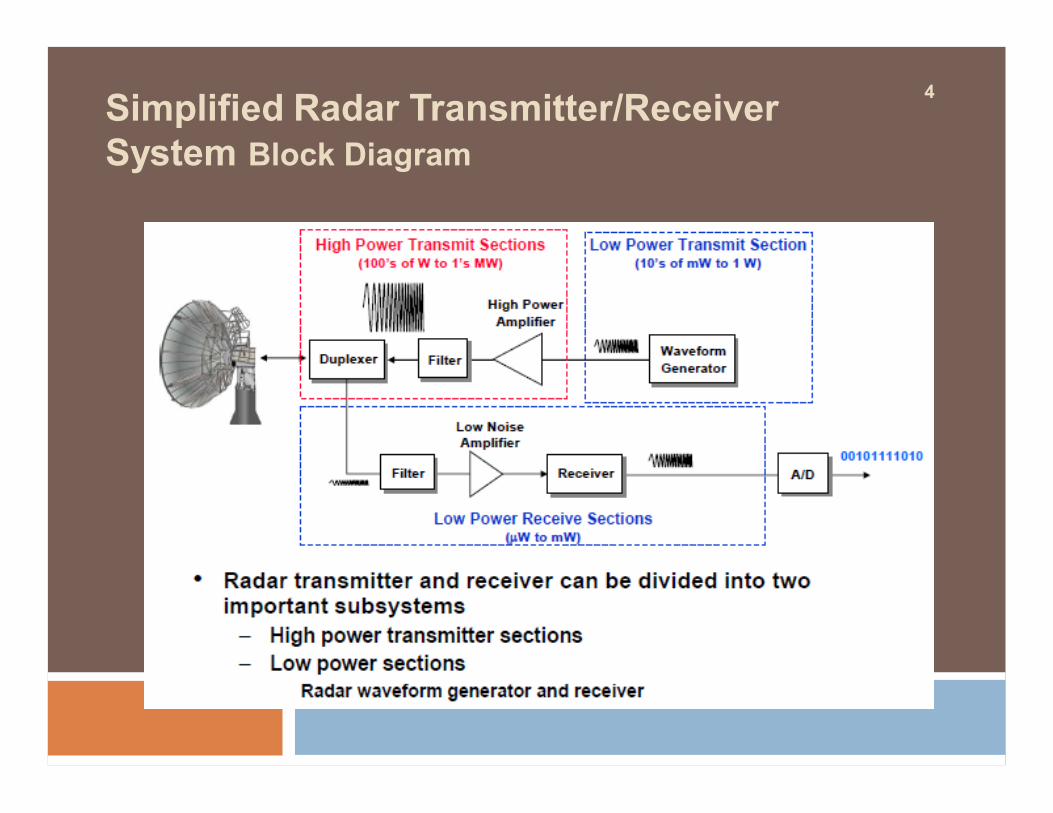
4Simplified Radar Transmitter/Receiver System Block Diagram

5Radar Range Equation RevisitedParameters Affected by Transmitter/Receiver
Ø Radar range equation for search (S/N = signal to noise ratio)
•S/N of target can be enhanced by -Higher transmitted power Pav-Lower system losses L-Minimize system temperature Ts

6
OutlineIntroduction
¨ Radar Transmitter Overview v High Power Amplifier
¨ Radar Waveform Generator and Receiver
¨ Radar Transmitter/Receiver Architecture
¨ Radar Antennas
¨ Radar Displays
¨ Summary

7
Power Amplification Process
Amplification occurs in multiple stages üDriver amplifiers ü High power amplifier
qRequirement for power amplifier ü Low noise ü Minimum distortion to input signal

8
Method to Obtain Higher Power
Higher transmitted power can be obtained by combining multiple amplifiers in parallel
v Lower efficiency (due to combiner losses)v Increased complexity
HPA = High Power Amplifier

9
Types of High Power Amplifiers
¨ Vacuum tube amplifiers and solid state amplifiers

10Average Power Output Versus Frequency Tube Amplifiers versus Solid State Amplifiers

11
Power Amplifier Examples
Ø Tube amplifiers § Klystrons§ Travelling wave tubes
Ø Solid State amplifiers§ Solid state power transistors
Criteria for choosing high power amplifiervAverage power output as a function of frequency vTotal bandwidth of operation v Duty cyclev Gainv Mean time between failure (MTBF)
etc…

12MIT/LL Millstone Hill Radar Klystron Tubes (Vacuum Devices)
• Originally designed in early 1960’s

13How Big are High Power Klystron Tubes ? Millstone Hill Radar Transmitter Room

14Photograph of Traveling Wave Tubes Another Type of Tube Amplifiers

15Example of Solid State Transmitter Radar Surveillance Technology Experimental Radar (RSTER)

16Solid State Active Phased Array Radar PAVE PAWS
PAVE PAWS§ First all solid state active aperture electronically steered phased array
radar§ UHF Band § 1792 active transceiver T/R modules, 340 W of peak power each

17
OutlineIntroduction v Radar Transmitter Overview
--- High Power Amplifier--- Duplexer
v Radar Waveform Generator and Receiver v Radar Transmitter/Receiver Architecturev Radar Antennasv Radar Displaysv Summary

18
Radar Transmitter/Receiver Timeline
Sensitive radar receiver must be isolated from the powerful radar transmitter
----Transmitted power typically 10 kW – 1 MW ----Receiver signal power in 10’s μW – 1 mW
§Isolation provided by duplexer switching PRI = Pulse Repetition Interval
19
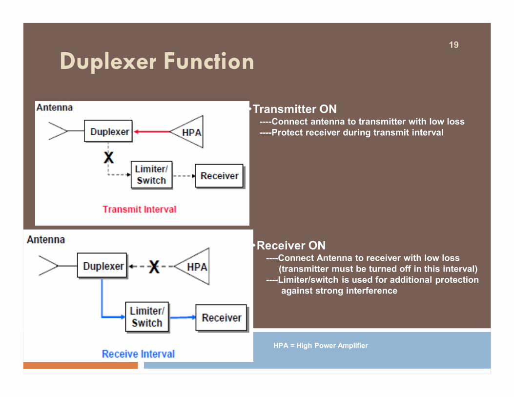
Duplexer Function
vTransmitter ON----Connect antenna to transmitter with low loss----Protect receiver during transmit interval
vReceiver ON----Connect Antenna to receiver with low loss
(transmitter must be turned off in this interval)----Limiter/switch is used for additional protection
against strong interference
HPA = High Power Amplifier

20
Outline
¨ Introduction
¨ Radar Transmitter Overview
Radar Transmitter/Receiver Architecture
¨ Radar Antennas
¨ Radar Displays
¨ Summary

21
Simplified Functional Descriptions
§Waveform generator and receiver share several similar functions-------Amplification, filtering and frequency conversion

22Frequency Conversion Concepts
§Up converter translates the waveform frequency to a higher frequency \
§Reason: Waveform generation less expensive at lower frequency
§Down converter translates the receive frequency to a lower frequency
§Reason: Dynamic range of A/D converter higher at lower frequency

23Simplified System Block Diagram Waveform Generator and Receiver
§This example shows only a single stage conversion -----In general, design based on multiple stage of frequency conversion are employed
§Multiple stages of amplification and filtering are also used

24
Outline
¨ Introduction
¨ Radar Transmitter Overview
¨ Radar Waveform Generator and Receiver
¨ Radar Transmitter/Receiver Architecture
¨ Summary

25
Dish Radars
KWAJALEIN
§Conventional radar transmitter/receiver design employed

26
Radar Antenna Architecture Comparison

27
Active Phased Array Radar
§Transmit/Receive function distributed to each module on array

28
Large Phased Arrays
Passive Array Radar Active Array Radar
Passive Array Radar
THAAD Radar
Cobra Dane15.3K active elements

29Digital Array Radar Architecture Digital on Receive
§Each active analog T/R module is followed by an A/D for immediate digitization----- Multiple received beams are formed digitally by the digital beamformer.

30Digital Array Example Digital On Receive
RSTER(14 Digital Receivers)

31Digital Array Radar Architecture II Digital on Transmit & Receive
Both waveform generation and receiver digitization are performed within each T/R module
-----Complete flexibility on transmit and receive

32
Summaryv Radar transmit function is accomplished in two stages:
-----Waveform generator creates low power waveform signal and up converts it to RF. -----Transmitter amplifies waveform signal
v Radar receiver performs filtering, amplification and down conversion functions-----Final received signal is fed to an A/D for digitization
v Radar transmit/ receive architecture is highly dependent on the antenna type -----Centralized architecture: dish radars, passive array radars-----Distributed architecture: active array and digital array radars

33
Radar Antennas

34
• Coverage maximum range (R) R4 ∝ P × A
• Resolution ability to recognize closely spaced targets
Beam Width: ∝ 1/A(λ)
Determines the radar's angular resolution
Typically fall between 1 and 10°.
Fundamental parameters:

35
SizesFrom proximity fuses used in artillery shells to phased-array radars housed in multistory buildings for detecting and tracking objects in
space.
In any one application:Size and cost may be limited either by the physical space available or by the importance of the radar information
Fundamental parameters:
36
Accurate pointing is a requirement inherent in all radar applications that measure target location.
Beam Scanning and Target Tracking.
To search for targets in a volume of space
Mechanically Electronically or both,
Electronic Scanning
Allows the beams to be scanned more rapidly by avoiding the inertia associated with moving mechanical components.
37
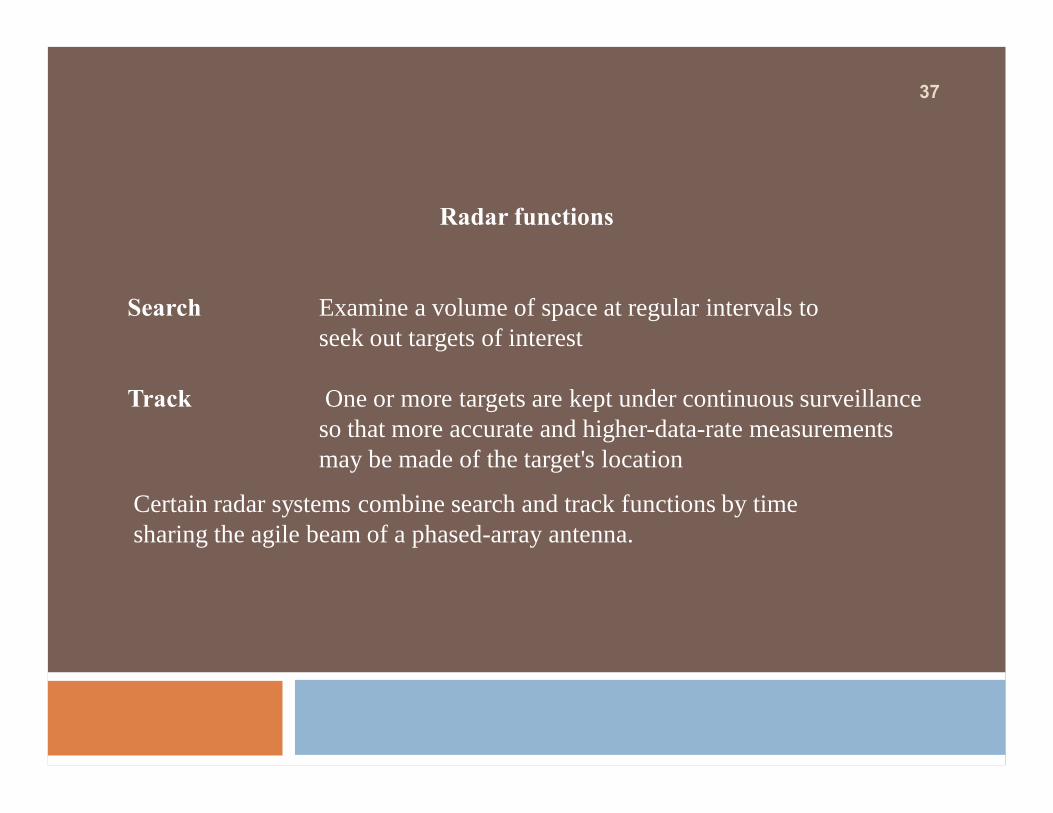
Radar functions
Search Examine a volume of space at regular intervals to seek out targets of interest
Track One or more targets are kept under continuous surveillance so that more accurate and higher-data-rate measurements may be made of the target's location
Certain radar systems combine search and track functions by time sharing the agile beam of a phased-array antenna.

38
Marine radar systems Smaller antenna and larger transmitter than would be used in a comparable land-based application are recommended.
Because of the great variety of radar applications, radar antennas are required to operate in many different environments.
At fixed sites The larger radar antennas are often protected by a radome, especially in arctic regions that experience heavy winds, ice, and snow.
Transportable systems Generally require that the antenna be disassembledfor transport.
Mobile systems Prepared to move rapidly from place to place and usually do not allow time for antenna disassembly.
39
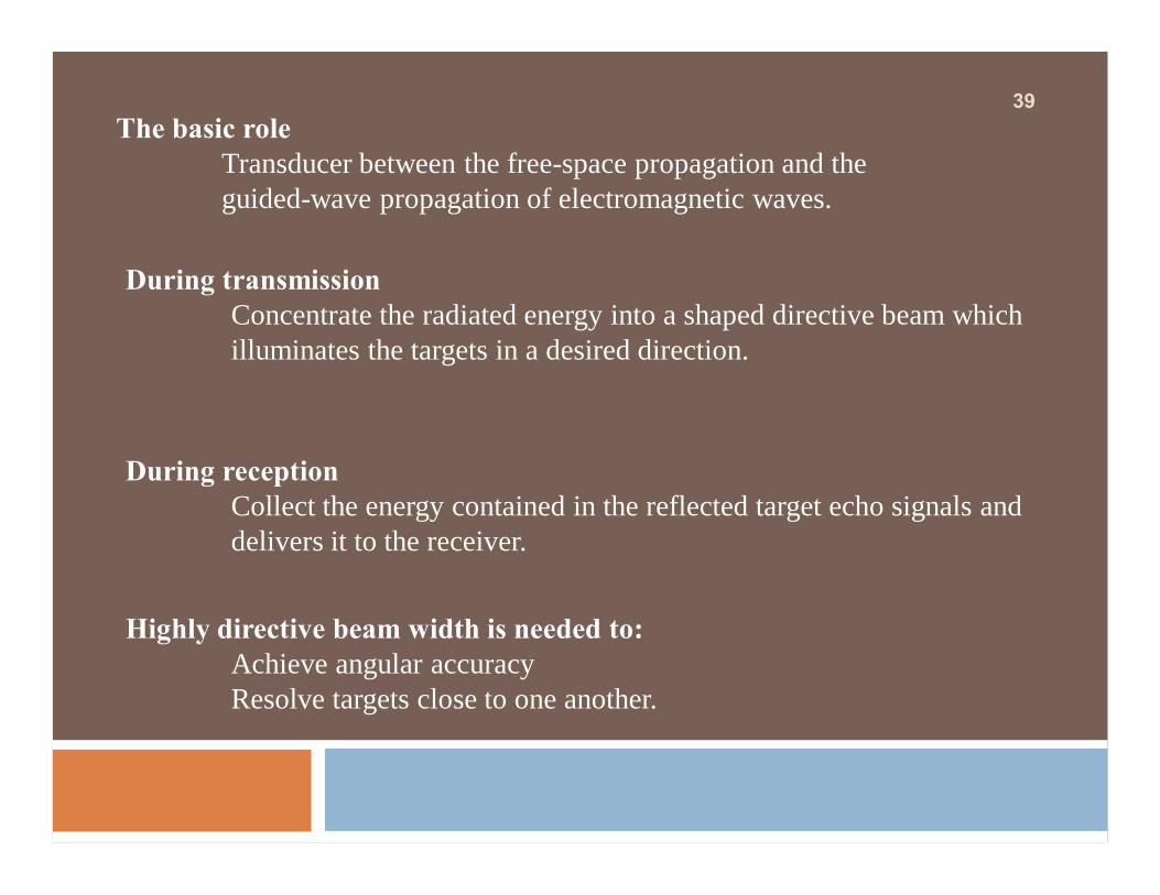
During transmissionConcentrate the radiated energy into a shaped directive beam which illuminates the targets in a desired direction.
The basic roleTransducer between the free-space propagation and the guided-wave propagation of electromagnetic waves.
During receptionCollect the energy contained in the reflected target echo signals and delivers it to the receiver.
Highly directive beam width is needed to:Achieve angular accuracyResolve targets close to one another.

40
Peak power Average power
Directivity & Gain
Radiation Patterns (Beamwidth & Sidelobe levels)
Polarization Cross-polarization rejection Bandwidth
Antenna Impedance:• Mismatch, SWR, Return Loss
Scan volume Scan time
Pointing accuracy Size
Radar-Antenna Parameters

41
The maximum directivity is defined as D(θ,φ) max = Do.The directivity range for any antenna is 0 < D(θ,φ) < Do.
The ratio of the radiation intensity in a given directionfrom the antenna to the radiation intensity averaged over all directions.
The directivity of an isotropic radiator is D(θ,φ) = 1.
Directivity (D)

42
Effective aperture
Directivity in dB
Gain = Directivity × efficiency

43
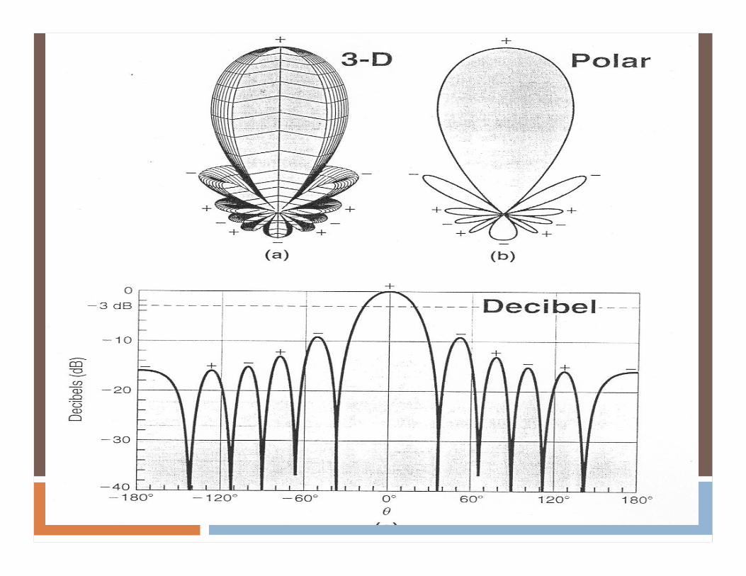
Antenna Radiation Patterns
Common parameters main lobe (boresight) half-power beamwidth (HPBW) front-back ratio (F/B) pattern nulls
Typically measured in two planes:
Vector electric field referred to E-field Vector magnetic field referred to H-field

44Antenna Pattern Parameters

45

46

47
In the transmit mode: Wasted radiated power
In the receive mode Receive from undesired directions
Sidelobe Levels
ExampleA radar for detecting low flying aircraft targets can receive strong ground echoes (clutter) through the sidelobes which mask the weaker echoes coming from low radar cross-section targets through the main beam..
The optimum compromise (tradeoff) between sidelobes, gain, and beamwidth is an important consideration for choosing or designing radar antennas

48
The sidelobe levels of an antenna pattern can be specified or described in several ways:
(1) The relative sidelobe level (the most common)
(2) Average level of all the sidelobes. (Airborne radar to suppress ground clutter)
(3) Median level half of the angular space has sidelobe levels above it and the other half has them below that level.
(not often used)
49

50(HPBW)
Solution
E(θ) at half power
0.707 = cos2 θ
θ = 33o
BW = 66o
Example
Find the (HPBW) of an antenna having
E(θ) = cos2 θ for 0o < θ < 90o

51
Defined relative to the E-field of antenna.
Horizontally Polarized (If the E-field is horizontal)
Vertically Polarized (If the E-field is vertical)
Polarization
Many existing radar antennas are linearly polarized, usually either vertically or horizontally; although these designationsimply an earth reference, they are quite common even for airborne or satellite antennas

52
CoCo--Polarization and CrossPolarization and Cross--Polarization Polarization
CoCo--PolarizationPolarizationThe desired polarization (the main polarization) (COPOL)
CrossCross--PolarizationPolarizationThe undesired orthogonal polarization (CROSSPOL).
Co-polarized antenna pattern
Azimuth Angle
Rel
ativ
e Po
wer
X-polarized patttern
XPD
A well designed antenna will have CROSSPOL components at least 20 dB below the COPOL in the main-beam region, and 5 to 10 dB below in the side lobe regions.

53
Antenna Impedance
Rr - Antenna radiation resistance (radiation)RL - Antenna loss resistance (ohmic loss)
The complex antenna impedance is
RA = Rr + RL
ZA = RA + j XA
RA - Antenna resistance [(dissipation ) + radiation]
XA - Antenna reactance [(energy storage) antenna near field]
ZA
54
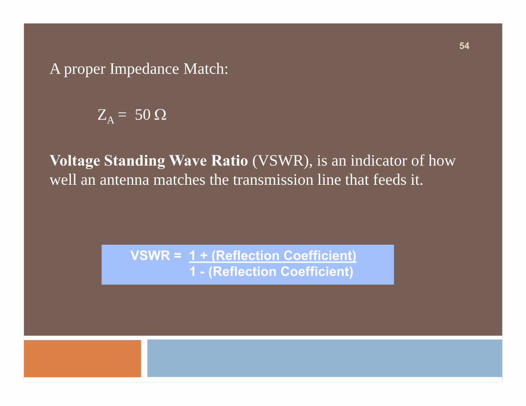
A proper Impedance Match:
ZA = 50 Ω
Voltage Standing Wave Ratio (VSWR), is an indicator of how well an antenna matches the transmission line that feeds it.
VSWR = 1 + (Reflection Coefficient)1 - (Reflection Coefficient)

55
Return Loss (RL) 10 log (Pin/Pr)
RL = 13.9dB ~ VSWR = 1.5
RL = 20dB ~ VSWR = 1.2
Pin
Pr
VSWR Return Loss Transmission Loss
1.0:1 ∞ 0.0 dB
1.2:1 20.83 dB 0.036 dB
1.5:1 13.98 dB 0.177 dB
5.5:1 3.19 dB 2.834 dB
56
Reflector Antennas

57Some Types of Reflector Antennas
Paraboloid Parabolic cylinder Shaped
Stacked beam Monopulse Cassegrain

58Parabolic reflectors still serve as a basis for many radar They provide:
Maximum available gainMinimum beamwidthsSimplest and smallest feeds.
Ga (dBi) = 10 log10 η [ 4 π Aa / λ2 ]
and β= 70 λ / D
Ga = Antenna Directive Gain
η = Aperture Efficiency (50-55%)
Aa = Antenna Aperture Area
λ = Wavelength
β = 3 dB HPBW

59
Basic Geometry and OperationFor a parabolic conducting reflector surface of focal length f with a feed at the focus F.In rect. coordinates
z = (x2 + y2)/4fIn spherical coordinates
ρ = f sec2 ψ/2
tan ψo/2 = D/4f

60Aperture angle θ = 2ψo

61
A spherical wave emerging from F and incident on the reflector is transformed after reflection into a plane wave traveling in the positive z direction
Reflectors with the longer focal lengths, which are flattest and introduce the least distortion of polarization and of off-axis beams, require the narrowest primary beams and therefore the largest feeds.

62
For example, the size of a horn to feed a reflector of f/D = 1.0 is approximately 4 times that of a feed for a reflector of f/D = 0.25. Most reflectors are chosen to have a focal length between 0.25 and 0.5 times the diameter.
As side lobe levels are reduced and feed blockage becomes intolerable, offset feeds become necessary.
Offset resultsunsymmetrical illumination.

63
The corners of most paraboloidal reflectors are rounded or mitered to minimize the area and especially to minimize the torque required to turn the antenna.
The deleted areas have low illumination and therefore least contribution to the gain.
Circular and elliptical outlines produce side lobes at all angles from the principal planes. If low side lobes are specified away from the principal planes, it may be necessary to maintain square corners, as

64Parabolic-Cylinder Antenna
It is quite common that either the elevation or the azimuth beam must be steerable or shaped while the other is not.
A parabolic cylindrical reflector fed by a line source can accomplish this at a modest cost.
The line source feed may assume many different forms ranging from a parallel-plate lens to a slotted waveguide to a phasedarray using standard designs.
The parabolic cylinder has application even where both patterns are fixed in shape.

65Elevation beam shaping incorporatesa steep skirt at the horizon
Allow operation at lowelevation angles without degradationfrom ground reflection
A vertical array can produce muchsharper skirts than a shaped dish ofequal height can, since a shaped dishuses part of its height for high-anglecoverage.
Parabolic cylinders suffer from largeblockage if they are symmetrical, and theyare therefore often built offset. Properlydesigned, however, a cylinder fed by anoffset multiple-element line source canhave excellent performance.

66Shaped Reflectors.Fan beams with a specified shape are required for a variety ofreasons. The most common requirement is that the elevation beamprovide coverage to a constant altitude.The simplest way to shape the beam is to shape the reflector.
Each portion of the reflector isaimed in a different directionand, to the extent that geometricoptics applies, the amplitude atthat angle is the integrated sumof the power density from thefeed across that portion.

67Elimination of blockage.
A large fraction of the aperture is not used in forming the mainbeam. If the feed pattern is symmetrical and half of the power isdirected to wide angles, it follows that the main beam will usehalf of the aperture and have double the beamwidth. Thiscorresponds to shaping an array pattern with phase only and mayrepresent a severe problem if sharp pattern skirts are required. Itcan be avoided with extended feeds.
Limitation

68
Multiple Beams and Extended Feeds• A feed at the focal point of a parabola forms a beam parallel
to the focal axis.
• Additional feeds displaced from the focal point form additional beams at angles from the axis.
This is a powerful capability of the reflector antenna to provide extended coverage with a modest increase in hardware
Each additional beam can have nearly full gain, and adjacent beams can be compared with each other to interpolate angle.
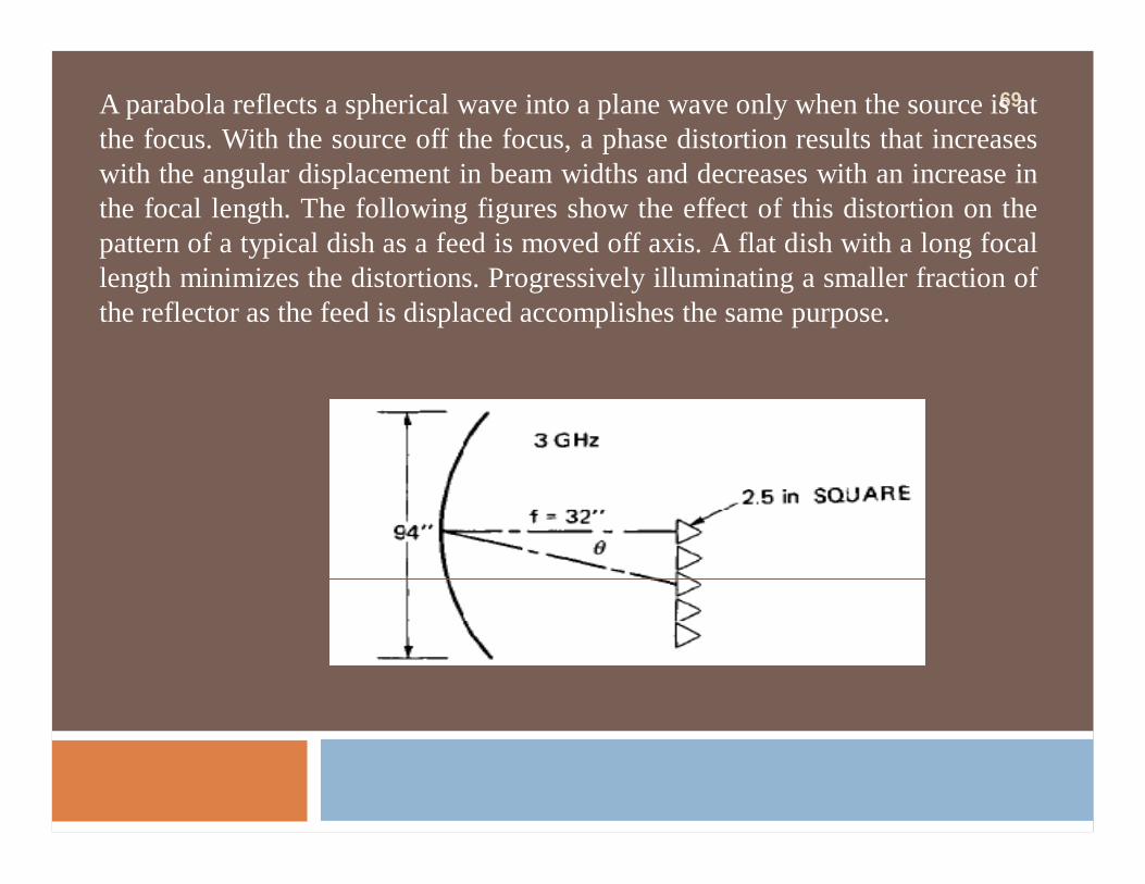
69A parabola reflects a spherical wave into a plane wave only when the source is atthe focus. With the source off the focus, a phase distortion results that increaseswith the angular displacement in beam widths and decreases with an increase inthe focal length. The following figures show the effect of this distortion on thepattern of a typical dish as a feed is moved off axis. A flat dish with a long focallength minimizes the distortions. Progressively illuminating a smaller fraction ofthe reflector as the feed is displaced accomplishes the same purpose.

70Patterns for off-axis feeds.

71AN/TPS-43 multiple-beam antenna

72
Monopulse is the most common form of multiple beam antenna, normally used in tracking systems in which a movable antenna keeps the target near the null and measures the mechanical angle, as opposed to a surveillance system having overlapping beams with angles measured from RF difference data.
Monopulse Feeds
Two basic monopulse systems
Amplitude comparison
Phase comparison

73
Amplitude comparison is far more prevalent in radar antennas
The sum of the two feed outputs forms a high-gain (target detection)
Low-side lobe beam
The difference forms a precise deep null at boresight(Angle determination)
Azimuth and elevation differences can be provided
If a reflector is illuminated with a group of four feed elements, aconflict arises between the goals of high sum-beam efficiency andhigh difference-beam slopes. The former requires a small overallhorn size, while the latter requires large individual horns.

74
Some of the shortcomings of paraboloidal reflectors can beovercome by adding a secondary reflector. The contour of theadded reflector determines how the power will be distributedacross the primary reflector and thereby gives control overamplitude in addition to phase in the aperture.
Multiple-Reflector Antennas
This can be used to produce very low spillover or to produce aspecific low-sidelobe distribution. The secondary reflectormay also be used to relocate the feed close to the source orreceiver. By suitable choice of shape, the apparent focal lengthcan be enlarged so that the feed size is convenient, as issometimes necessary for monopulse operation.
75
The Cassegrain antenna, derived from telescope designs, isthe most common antenna using multiple reflectors. Thefeed illuminates the hyperboloidal subreflector, which inturn illuminates the paraboloidal main reflector.The feed is placed at one focus of the hyperboloid and theparaboloid focus at the other. A similar antenna is thegregorian, which uses an ellipsoidal subreflector in place ofthe hyperboloid.

76
blockage elimination

77
FEEDS
At lower frequencies (L band and lower) dipole feeds are sometimes used, particularly in the form of a linear array of dipoles to feed a parabolic-cylinder reflector.
Other feed types used in some cases include waveguide slots, troughs, and open-ended waveguides, but the flared waveguide horns are most widely used

78Front Feed Offset Feed Cassegrain Feed

79
Gregorain Feed Simple Pyramidal horn
Corrugated Conical Horn
Simple Conical

80
Other considerations include operating bandwidth and whether the antenna is a single-beam, multibeam, or monopulse antenna.
The feeder in the receive mode• Must be point-source radiatorsIn the transmit mode, it• Must radiate spherical phase fronts if the desired
directive antenna pattern is to be achieved.• Must also be capable of handling the required
peak and average power levels withoutbreakdown under all operational environments
• Must provide proper illumination of the reflectorwith a prescribed amplitude distribution andminimum spillover and correct polarization withminimum cross polarization.

81
Rectangular (pyramidal) waveguide horns propagating the dominant TE01 mode are widely used because they meet the high power and other requirements, although in some cases circular waveguide feeds with conical flares propagatingthe TE11 mode have been used.
These single-mode, simply flared horns suffice for pencil-beam antennas with just one linear polarization.

82
In some applications it is desirable to have very low sidelobes from a pencil-beam reflector. In this instance, considerable improvement can be obtained by the use of metal shielding around the reflector aperture.
The typical sidelobes areat about 0 dBi, which for most reflectors represents a value of the order of -30 to -40 dB below the peak gain. With a shielding technique, the far-out sidelobes can be reduced to -8OdB.
Shielded-Aperture Reflectors

83Shielded-Aperture Reflectors
The simplest approach to shielding the reflectoris a cylindrical "shroud," or tunnel, of metalaround the edge of a circular reflector. If theaperture is elliptical in cross section, an ellipticalcylinder can be used.
Radome:
Reducing wind loading & Protection against Ice, Snow and Dirt

84Typical Antenna Performance
Standard Parabolic
Cross-polar of all types is of the order of 30 dB
• Without Shroud
•• With Shroud
Frequency Diameter Gain HPBW F/B Ratio• ••
85
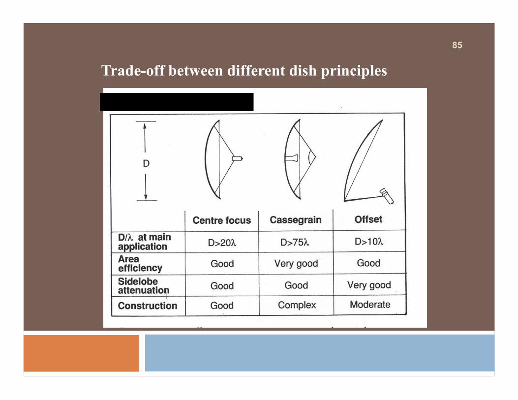
Trade-off between different dish principles

86
Typical ParabolicTypical ParabolicAntenna Gain in dBiAntenna Gain in dBi
Antenna Diameter
Freq
uenc
y
2 ft(0.6m)
4 ft(1.2m)
6 ft(1.8m)
8 ft(2.4m)
10 ft(3.0m)
12 ft(3.7m)
15 ft(4.5m)
2 GHz 19.5 25.5 29.1 31.6 33.5 35.1 374 GHz 25.5 31.6 35.1 37.6 39.5 41.1 43.16 GHz 29.1 35.1 38.6 41.1 43.1 44.6 46.68 GHz 31.6 37.6 41.1 43.6 45.5 47.1 49.111 GHz 34.3 40.4 43.9 46.4 48.3 49.9 51.815 GHz 37 43.1 46.6 49.1 51 52.6 NA18 GHz 38.6 44.6 48.2 50.7 NA NA NA22 GHz 40.4 46.4 49.9 NA NA NA NA38 GHz 45.1 51.1 NA NA NA NA NA

87
Reflector Efficiency
Well-designed antennas have efficiency ratings of 45 - 65%
Efficiency Factor Affected By :• Feed Illumination• Aperture Blockage• Reflector Surface Tolerance• Efficiency can never be 100%

88
Unwanted SignalsUnwanted Signals
Scattering Diffraction Spillover

89
Front to Back RatioFront to Back RatioDirection of SignalDirection
of SignalDirection of Signal
Shielded Shielded AntennaAntenna
Focal Plane Focal Plane AntennaAntenna
Standard Parabolic Standard Parabolic AntennaAntenna

90
Parabolic Reflector Beamwidth
0.3 m 0.6 m 1.2 m 1.8 m 2.4 m 3 m 3.7 m 4.5 m2 GHz 35 17.5 8.75 5.83 4.38 3.5 2.84 2.33
6 GHz 11.67 5.83 2.92 1.94 1.46 1.17 0.95 0.78
8 GHz 8.75 4.38 2.19 1.46 1 0.88 0.71 0.58
11 GHz 6.36 3.18 1.59 1 0.8 0.64 0.52 0.42
14 GHz 5 2.5 1.25 0.83 0.63 0.5 0.41 0.33
18 GHz 3.89 1.94 0.97 0.65 0.49 0.39 0.32 0.26
23 GHz 3 1.52 0.76 0.51 0.38 0.3 0.25 0.2
38 GHz 1.84 0.92 0.46 0.31 0.23 0.18 0.15 0.12
Beamwidth in Degrees
Diameter
Freq
uenc
y
3dB

91
Phased Array Antennas
Antenna array - a configuration of multiple antennas (elements) arranged to achieve a given radiation pattern.
Linear array - antenna elements arranged along a straight line.Circular array - antenna elements arranged around a circular ring.Planar array - antenna elements arranged over some planar
surface (example - rectangular array).Conformal array - antenna elements arranged to conform to some
non-planar surface (such as an aircraft skin)

92
1. General array shape (linear, circular, planar, etc.).2. Element spacing.3. Element excitation amplitude.4. Element excitation phase.5. Patterns of array elements.
Array Design Variables
An array of identical elements which achieves a given patternthrough the control of the element excitation phasing.
Phased array
Phased arrays can be used to steer the main beam of the antenna without physically moving the antenna.

93
The capability of rapidly and accurately switching beams permits:
• Multiple radar functions to be performed, interlaced in time or even simultaneously.
• An electronically steered array radar may track a great multiplicity of targets, illuminate a number of targets with RF energy and guide missiles toward them, perform complete hemispherical search with automatic target selection, and hand over to tracking
• It may even act as a communication system, directing high-gain beams toward distant receivers and transmitters.
• Complete flexibility is possible; search and track rates may be adjusted to best meet particular situations, all within the limitations set by the total use of time.

94
The capability of rapidly and accurately switching beams permits:
• The antenna beamwidth may be changed to search some areas more rapidly with less gain.
• Frequency agility is possible with the frequency of transmission changing at will from pulse to pulse or, with coding, within a pulse. Very high powers may be generated from a multiplicity of amplifiers distributed across the aperture. Electronically controlled array antennas can give radars the flexibility needed to perform all the various functions in a way best suited for the specific task at hand. The functions may be programmed adaptively to the limit of one's capability to exercise effective automatic management and control.

95
RADAR DISPLAYS

96
General Display Types
¨ RAW VIDEO¤ display the detected and amplified target return signal
(and the receiver noise). ¤ It requires a human operator to interpret the various
target noise and clutter signals.SYNTHETIC VIDEO It uses a computer to clean up the display by eliminating
noise and clutter and creating it's own precise symbol for each target.

97SYNTHETIC VIDEO

98SEARCH AND ACQUISITION RADARS
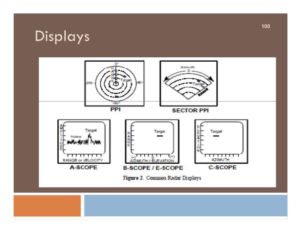
They generally use either a PPI or a sector PPI display¨ as shown.¨ PPI displays can be either raw video or synthetic video. ¨ PPI scope (plan position indicator). ¨ Polar plot of direction and distance. ¨ Displays all targets for 360 degrees. ¨ Sector PPI scope. ¨ Polar plot of direction and distance. ¨ Displays all targets within a specific sector. ¨ Origin may be offset so that "your" radar position may¨ be off the scope.
99
RADARS
Usually use some combination of A,B, C, or E scope displays.
There are many other types ofdisplays that have been used at one timeor another - including meters - but thoselisted here are the most common in usetoday.
100
Displays
101A-SCOPE ¨ Target signal amplitude vs range or velocity.
¨ Displays all targets along pencil beam for selected rangelimits.
¨ Displays tracking gate. Usually raw video.
¨ Some modern radars have raw video a-scopes asan adjunct to synthetic video displays.
¨ Must be used with a separate azimuth andelevation display of some sort.
¨ Also called a range scope (R-Scope).

102B-SCOPE
¨ Range vs azimuth or elevation.
¨ Displays targets within selected limits.
¨ Displays tracking gate. May be raw or synthetic video.
¨ Surface radars usually have two. One azimuth/one elevation which canresult in confusion with multiple targets.

103C-SCOPE
¨ Azimuth vs elevation. Displays targets within selected limits of az and el.
¨ Displays tracking gate. May display bull's-eye or aim dot.
¨ May have range indicator inserted typically as a marker along one side.Usually synthetic video.
¨ Pilots eye view and very common in modern fighter aircraft heads updisplays for target being tracked.
¨ Could be used in any application where radar operator needs an "aiming" or"cross hair" view like a rifle scope.
104
E-SCOPE
Elevation vs Range similar to a B-scope,with elevation replacing azimuth.

105
QUERIES!!!
THANK YOU

106
References
¨ Skolnik, M., Introduction to Radar Systems, New York, McGraw-Hill, 3rd Edition, 2001
¨ Skolnik, M., Radar Handbook, New York, McGraw-Hill, 2nd Edition, 1990


