R A D I O F R E Q U E N C Y S Y S T E M S
T h e C l e a r C h o i c e ™
Please visit us at www.rfsworld.com
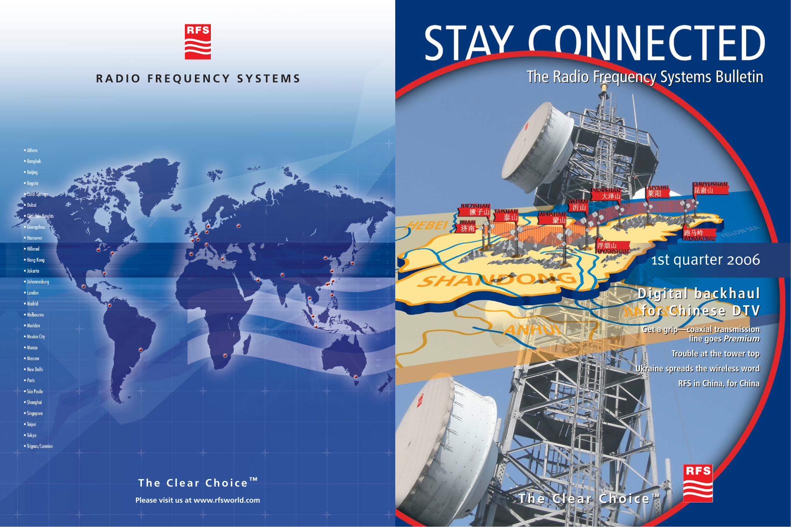
1st quarter 2006
The Radio Frequency Systems BulletinThe Radio Frequency Systems Bulletin
T h e C l e a r C h o i c e ™T h e C l e a r C h o i c e ™
Digita l backhaulfor Chinese DTV Get a grip—coaxial transmission
line goes Premium
Trouble at the tower top
Ukraine spreads the wireless word
RFS in China, for China
Digita l backhaulfor Chinese DTV Get a grip—coaxial transmission
line goes Premium
Trouble at the tower top
Ukraine spreads the wireless word
RFS in China, for China
These are just the tip of the iceberg. As Asia
approaches the registration of the region’s
one billionth subscriber some time in the next
few months, it is clear that the wireless world
will, in many respects, be significantly influ-
enced by this region’s unique requirements
and broad range of cultures and economies.
This evolutionary stage represents a major
wireless market leap—it will not only change
the face of the global mobile industry,
but provide a major impetus for growth and
evolution.
The challenge from an RF technology
perspective will be to understand and come
to terms with the diversity and the unique
needs of the Asian region. Radio Frequency
Systems has long been aware of these, and
the error of many competing wireless
technology groups in trying to apply a ‘one-
size-fits-all’ approach, driven from outside
the region. The wireless answer for Asia is
simple: one size does not fit all, and the
diversity of the region must be addressed
by solutions that are tailored at a local level.
As a truly global organization, RFS is ideally
positioned to address such a market. For over
a decade, we have made it our business to
grow local participation and knowledge of
the Asian wireless market. It has long been
our view that RF solutions need to be tailored
for any region or country, not enforced from
the outside. Our 11 technical support and
manufacturing centers across Asia, coupled
with our extensive network of in-country
agencies and distributors, ensure extensive
RFS support throughout the region.
In essence, RFS truly knows and understands
Asia, as we have made it is one of our global
‘homes’. We plan to grow our presence in
this exciting and dynamic area and will
continue to support carriers and OEMs in this
important ‘next phase’ of wireless develop-
ment—the Asianizing of global mobile.
growth has recently been explained in a
report from the London Business School—
a rise of just ten mobile phones per 100 peo-
ple can boost GDP growth by 0.6 percentage
points.
Asia, because of its sheer scale and almost
region-wide acceptance and early-adoption
of new wireless technologies, is now clearly
taking control of the technology and
adapting it to suit the region. Over the past
few years, we have seen many small-scale
examples of its potential to drive and mold
the market—Japan’s leading development of
3G telecommunications, the Philippines
national adoption and promotion of the
short message services (SMS), and China’s
unique and innovative Xiaolingtong or ‘Little
Smart’ limited mobility networks. In India’s
case, a recently announced government
objective targets a three- or four-fold increase
in mobile penetration (currently at around
50 million) over the next three years.
Uniquely Indian wireless solutions will
play a major role here.
2
The Asianiz ing of global mobi le03 Editorial
The Asianizing of global mobile
04 What’s NewRFS analyzing broadcast RF remotely
BDAs go dual-band
Three-foot dish gives FCC Cat. Aperformance at 11 GHz
MD series duplexers tailor-made
06 Cover StoryDigital backhaul for Chinese DTV
08 Feeder SystemsGet a grip—coaxial transmission line goes Premium
12 Wireless CommunicationsRFS in China, for China
Trouble at the tower top
15 BroadcastBroadband RF now, mobileTV later
16 Regional FocusUkraine spreads the wireless word
18 In TouchBarcelona is home to 3GSM 2006
RFS microwave the safe path in Arizona
Metro Budapest gets wireless coverage
Growing with Greece
DTF demystified at NATE 2006
Digital backhaul for Chinese DTV
A digital upgrade to Shandong Broadcast’s650-kilometer (400-mile) microwavebackhaul network features total microwave antenna systems from RFS.The Chinese broadcaster is now one step closer to DTV.
I N D E X
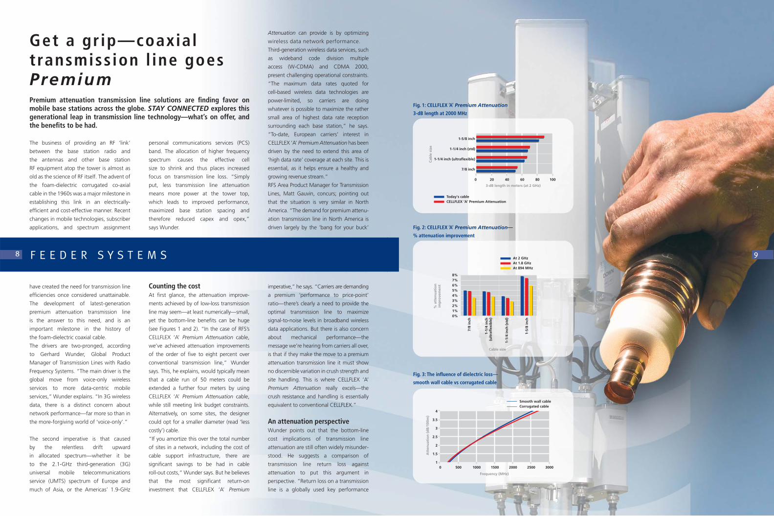
Get a grip—coaxial transmissionline goes Premium
Premium attenuation transmission linesolutions are finding favor on mobilebase stations across the globe. STAY CONNECTED explores this generational leap in transmission line technology.
3E D I T O R I A LIMPR
INTRadio Frequency Systems
WorldWideWeb: http://www.rfsworld.com
Publisher: Jörg SpringerExecutive Editor/Editor Asia Pacific South: Peter WaltersEditor EMAI: Regine SulingEditor Americas North: Ann PolanskiEditor Americas South: Luciana Del NeroEditor Asia Pacific North: Sammie QianManaging Editor: Allan AldersonProduction Editor: Christian MichatschArt Director: Matthias Schwedt
Authors: Allan Alderson, Irina Ewert, Dr. Ellen Gregory, Anita TalbergPhotos: RFS archives, Mick Bennett, Janus Hartvig,Tony Koopmans, Shelton Muller, Ann Polanski, Natalia Rivkina, Zhou Xiaoming (Alcatel ShanghaiBell), Harald ZietzCover photography: Zhou Xiaoming (Alcatel Shanghai Bell)Cover art: Matthias Schwedt
Print: Print Design, Minden
Layout and Graphics:inform Advertising, Hannover
Editorial Services:Relate Technical Communications, Melbourne
Trademarks: CELLFLEX®, BDA®, FLEXWELL®, MicroTenna™, Optimizer®, RADIAFLEX®, Radio Frequency Systems®, RFS®, RFS CompactLine®,SlimLine®, RGFLEX® and The Clear Choice™ are trademarks, service marks or registered trademarksof Radio Frequency Systems.
Ukraine spreads the wireless word
One of the fastest growing wireless marketsin the world, Ukraine leans heavily on RFStechnologies as the foundation for its nationwide RF networks.
166
RFS in China, for China
As anticipation builds for the eruption of third-generation wireless communica-tions into China, RFS intensifies its Shanghai RF conditioning and base station antenna design and manufacturing activities.
12
Trouble at the tower top
As the FCC auctions wireless spectrum for future services in the US, the cocktail of co-located technologies and frequencies at the tower top could interact with eachother in unpredictable ways.
14
8
A recent report from the industry research
group, In-Stat, has pointed out a market
trend that many in our sector had long
suspected—that Asia will soon represent the
largest market in the global mobile sector.
The report indicates that the Asian region as
a whole will become the world’s largest
mobile market within the next five to 10
years. It also predicts that the sector’s total
revenue in this region should, by 2009,
improve by more than 40 percent on its
2004 figure. In many respects, this ‘Asian
upswing’ represents a major turning-point
in mobile telecommunications.
The Asian region stretches from the Arabian
Peninsula in the West, to the Pacific island
nations of Japan and Taiwan in the East.
It is largely a ‘new’ entrant to the world of
mobile telecommunications—much of Asia
has only reached significant mobile telecom-
munications subscription levels within the
past five years. Two key factors have aided
this recent surge in subscriber count:
extensive deregulation across the region’s
telecommunications sector, and a marked
upturn in regional commerce, notably in the
manufacturing and service provision sectors.
The Asian regional mobile market differs
markedly from its counterparts of Western
Europe and North America in many ways. A
common theme runs through almost all
these differences—the readiness of Asia’s
people to adopt new wireless technologies
and accept fast-paced change, coupled with
the diversity of the wireless markets across
the region. The region also exhibits notably
less penetration of personal computers, and
as a result, less wired Internet access. This
presents as a natural driver toward wireless
connectivity.
In many respects, it is the issue of diversity
that characterizes Asia as a whole. This vast
region is home to around 60 percent of the
world’s population and spans an area over
40 million square kilometers (15 million
square miles). It embraces the most diverse
range of peoples, languages, terrains,
cultures and economies on the planet.
A snapshot of the mobile telecommunica-
tions scenario in three countries of the region
illustrates this amazing diversity—a diversity
that incorporates both ends of the market
spectrum. The Chinese market tripled its
subscriber penetration in the period 2000
to 2004, taking it from ‘insignificant’ status,
to what is today the world’s largest single
mobile market. Japan is by far the world’s
earliest adopter of advanced wireless
technologies, and a market leader in the
roll-out and uptake of 3G telecommunica-
tions. Taiwan represents a similarly amazing
wireless market, boasting the world’s
highest percentage of mobile phone users
(over 100 percent) and a rapid move into
3G mobile services.
By contrast, the region is also home to
countries with notably small gross domestic
product (GDP) figures and some of the
world’s lowest mobile penetration levels.
What is interesting is that most of these small
GDP countries demonstrate extraordinarily
high levels of wireless subscriber growth. The
economic reasoning behind such mobile
Stéphane KlajzyngierRadio Frequency Systems President

Allowing transmit and receive signals to share
a common antenna, Radio Frequency
Systems’ MD series duplexers deliver
exceptional levels of performance and
flexibility. Isolating the receiver signal from
that of the transmitter, the MD series
features high-quality tuners with zero back-
lash, and high selectivity to minimize out-of-
band interference. Additionally, the specific
design of each MD series duplexer is tailored
to exact customer requirements of band-
width, isolation and rejection figures.
“This is not an off-the-shelf product, it is
customized for the application and its
environment,” said Eddie Lee, RFS Area
Project Sales Manager for Wireless
Distributed Communication Systems. “How-
A breakthrough in microwave antenna
design by Radio Frequency Systems
provides an exciting new solution for point-
to-point communications in the US 11-GHz
band. The RFS SlimLine SU3-107FC
microwave antenna is the first antenna on
the market—smaller than four feet in
size—to meet the stringent US Federal
Communications Commission (FCC) part
101 Category A requirements in this band.
RFS Area Product Manager, Asad Zoberi,
said that the feed system of the three-foot
SU3-107FC has been re-designed. “Until
now, the only way to meet the FCC
Category A requirements in the 11-GHz
band was to use a four-foot antenna,” he
said. “But this is often an overkill from
the required system gain perspective.
Furthermore, end users are constantly
challenged by zoning and permit
4 W H A T ’ S N E W
RFS analyz ing broadcastRF remotelyWith the advent of digital television (DTV),
and a global trend towards remote monitor-
ing of broadcast sites, Radio Frequency
Systems has developed a new RF system
monitor. The new system demonstrates
superior accuracy and functionality than any
other on the market, and
can provide remote
access. Incorporating 50
configurable inputs, it
can handle up to 16
transmitters, and an
antenna system with four
main feeders.
The new RF system
monitor is used primarily
for monitoring forward/reflected trans-
mitter power and for mimic display
of U-Link/motorized switch configurations.
Beyond this, it has the ability to analyze
and store a wide range of collected data
for up to three years. According to
Graham Broad, RFS Product Development
Manager, unmanned broadcast sites
really benefit from the data logging feature.
“The operator needs some immediate analy-
sis to see what is actually going on inside the
transmitting system—we can do that with
the new RF system monitor,” said Broad.
Founded on microprocessor technology, the
new RF system monitor has superior accuracy
for measuring either peak or true root
mean square (RMS) power of complex
waveforms. It has the ability to compensate
for the effects of temperature variations,
and independently evaluate non-linear
multi-channel systems.
The operator interface has also been
optimized, through the implementation of
an active mimic display on a tablet PC.
Normally integrated into the U-Link frame,
this display allows easy network configura-
tion and connection to the operator’s local
network. More functionality can be achieved
through enabling Internet connectivity, plus
a Windows-based display allows the user
interface to be customized to suit.
In support of wireless coverage inside
buildings such as car parks and shopping
centers, Radio Frequency Systems has
developed one of the world’s first
dual-band bi-directional amplifiers (BDA).
The BDA amplifies the signal from a donor
base antenna, which is then re-distributed
via an indoor ‘service’ antenna system,
providing coverage without the need for
additional radios.
The new 48960 BDA supports US 800-MHz
and 900-MHz specialized mobile radio
(SMR) services in a single compact and
lightweight unit. This saves over
20 percent of the cost of two sin-
gle-band units. “The BDA has two
RF ports, one for connecting to
the donor antenna and another
to the service antenna. Inside the
unit, the signals are separately filtered for
out-of-band frequencies, but passed
BDAs go dual-bandthrough a common amplifier for either the
downlink or uplink. The amplifiers are
broadband to cover both the 800- or 900-
MHz bands,” said Ganesh Krishnan, RFS
Area Product Manager RF Conditioning.
Providing a high gain of 65-dB to the
signal at the base port, the 48960 BDA
Three-foot dish gives FCC Cat . A performance at 11 GHz
MD ser iesduplexers ta i lor-made
5
amplifies the weak signal to improve
coverage in the service area. The BDA also
has a high dynamic range of around 50 dB.
This feature allows the unit to withstand
stronger signals without getting
overloaded. In addition, the automatic
gain control (AGC) feature prevents the
amplifier from being overdriven, and also
ensures that the unit will not exceed US
Federal Communications Commission
(FCC) limits of spurious emissions. Unlike
other competition models, the AGC in
the 48960 BDA utilizes a true root-
mean-square (RMS) detector, which allows
the AGC to be accurately set with a single
tone, simulating a nearly true loaded signal
as experienced in the field.
ever, once a duplexer has been designed
and manufactured, then it becomes a
standard product as part of our MD series
range.” Four new MD series duplexers have
recently been added to this list of RFS stocked
products: the MD18-1L, the MD21-1L,
the MD21-1R and the MD25-1R. These
respectively support frequency bands 1710
to 1910 MHz, 1900 to 2300 MHz, 2000 to
2300 MHz, and 2300 to 2700 MHz.
The precise tailoring of each relates largely to
this tuning range, passband and isolation
applications—they want antenna solutions
that are smaller and more lightweight to
minimize the tower loading.”
According to Zoberi, the US 11-GHz band
(10.7 to 11.7 GHz) is an ideal option for
point-to-point communications, with links
typically spanning eight to 32 kilometers
(five to 20 miles). It has capacity and
rain-attenuation advantages over the
10-GHz and 18-GHz bands respectively;
however the band has been underutilized
due to lack of smaller antennas that meet
the stringent FCC regulations.
The SU3-107FC is a new addition to
the RFS SlimLine family of ultra high-
performance microwave antennas, and
exhibits all the features and benefits of the
range. This includes a robust mechanical
design and lightweight construction from
corrosion-resistant materials. As the only
antenna smaller than four feet to meet
FCC part 101 Category A requirements in
the 11-GHz band, it will facilitate
zoning and site permit acquisition,
making it the ideal solution for backhaul
applications.
requirement. The MD21-1L has a tuning
range of 1900 to 2300 MHz with a passband
of +/– 9 MHz, whereas the MD21-1R has a
slightly narrower tuning range of 2000 to
2300 MHz with a passband of +/– 3.5 MHz
“This enables the MD21-1R passband
isolation to be more than 80 dB, and the
MD21-1L more than 70 dB,” said Lee. “This
demonstrates to what extent we will
go to tailor the product to the customer’s
needs.”

tower-mounted antennas with the Alcatel
LSY 9600 radio in the equipment room
at the tower base. Featuring superior
transverse stability, flexibility and crush
strength, the FLEXWELL waveguide was
installed in continuous lengths between
50 and 100 meters (164 to 328 feet)—
depending on the height of the
tower—eliminating flange discontinuities
and facilitating installation. The premium
version is specially designed for high-
capacity radio systems, where low loss and
a very low VSWR is required.
Total system optimizedThe complete RFS system—from the
output of the radio to the antenna—was
fully optimized to meet the technical
specifications determined by Alcatel
Shanghai Bell. According Fei, RFS won the
contract based on the superior perfor-
mance of the complete system, which
offers unsurpassed reliability and longevity.
“RFS also provided supervision on site to
ensure the installation team was correctly
instructed in how to assemble the system,”
Fei says. “This included mounting of the
antenna in the correct position and
techniques for connecting the waveguide.”
Installation took a total of 21 days, with
another day for testing and commissioning
at each site.
The network finally went on-air in April
2005, and is currently supporting the
existing analog television services. “The
system is performing very well,” says Fei.
“It has all the capacity it needs and
more. Now Shandong Broadcast is one
step closer to realizing the full potential
of DTV.”
calculate the interference potential and to
design the radio link network. Other
aspects of the network design involved
allocations of polarization (vertical or
horizontal), frequency and gain for each
point-to-point link.
Long distance hopsThe resulting network utilizes frequency
channels in the 5-GHz band for all links,
except for the initial link between Jinan and
the first peak at Juezishan. For this short
five-kilometer (3-mile) hop, the 11-GHz
band was used. Most of the hops span
much greater distances, with three of
around 100 kilometers (62 miles) through
mountainous territory. “These are very long
distances for digital microwave point-
to-point links,” says Fei, “and they required
some special engineering.”
Common techniques used to improve the
signal-to-noise ratio for very long hops are
space and/or frequency diversity. The hop
essentially consists of two parallel point-to-
point links, operating on different channels
within the band, and separated by a vertical
distance of about 10 meters (33 feet). For
the Shandong Broadcast microwave
backhaul network, a combination of space
and frequency diversity were used for all
hops greater than 35 kilometers (22 miles)
in length.
The RFS antennas used in the installation
were predominantly 10-foot single-polarized
high-performance microwave antennas,
optimized for use in the 5-GHz band
(model DA10-44AD). In addition to a
robust and wind-resistant construction,
these antennas feature low voltage
standing wave ratio (VSWR) feed, planar
radome, and shroud for improving side
lobe suppression. More than 30 antennas
were deployed throughout the network
in varying combinations of vertical and
horizontal polarization.
Lengths of RFS FLEXWELL premium
elliptical waveguide EP46J connect the
7C O V E R S T O R Y
With the Chinese government expected
to name a digital television (DTV) broad-
casting standard by the end of 2005, the
nation’s terrestrial broadcasters are starting
to mobilize and plan for the anticipated
upgrade to digital services. Some broad-
casters will need to move fast once
the decision is announced, since analog
switch-off is already scheduled in some
provinces for as early as 2008. This means
they are looking at ways of getting a head
start—upgrading analog backhaul networks
to digital is one possible place to begin.
Shandong Broadcast is one such provincial
broadcaster faced with the 2008 analog
switch-off deadline. Located on the lower
reaches of the Yellow River, the coastal
Shandong Province overlooks the Korean
Peninsula and the Japan Archipelago. It is
one of China’s more densely populated
provinces, occupying a total area of 156,000
square kilometers (60,200 square miles) with
a population of over 90 million. As such,
Shandong is also one of the most developed
provinces, and will be part of the ‘first phase’
of China’s transition to DTV broadcasting.
To gear itself into readiness for DTV,
Shandong Broadcast recently completed an
extensive digital upgrade of its 650-kilometer
(400-mile) micro-wave backhaul network. As
the maincommunications backbone for the
broadcaster, the network transmits and dis-
tributes eight television channels from the
network operations center (NOC) in the
western city of Jinan. The new radio link
comprises 10 point-to-point hops, with
each tower also a prospective DTV broad-
cast site. From Jinan, it snakes east across
mountainous regions towards the coast,
where it terminates near Weihai.
Capacity plusAlcatel Shanghai Bell designed the new
radio link network, based on high-
performance microwave antenna systems
from Radio Frequency Systems. According
to Sindy Fei, RFS Area Product Manager for
Microwave Antenna Systems, an important
criteria for the network was that it be
future-proof. “Not only is the new network
ready for DTV when it’s launched, but it has
additional capacity built-in as well,” he
says. “At some later date it may even be
used for Internet services. The existing
antenna/radio systems are expandable to
double the current capacity of 155 mbps.”
The upgrade project was conceived in
March 2004, when it became clear that the
existing analog microwave backhaul
network would not accommodate either
the digital capability or the capacity
required for DTV. According to Fei, any
notions of deploying alternative backhaul
technologies were instantly dismissed: both
the coastal winds and mountainous terrain
of Shandong Province made microwave
radio links the most practical and cost-
effective option.
“It’s a very windy province, due to the prox-
imity of the sea,” says Fei. “Therefore RFS
microwave antennas, with their high
mechanical standard, were first choice. The
easy and fast installation was an additional
advantage, as optical fibers are very difficult
to install in mountainous terrain.”
Working with Alcatel Shanghai Bell, RFS
got involved early in the network design
process, due to the fact that only RFS
antennas satisfied the strict radiation
pattern required by the network planners.
The radiation pattern data were used to
6
Digita l backhaul forChinese DTVA digital upgrade to Shandong Broadcast’s 650-kilometer (400-mile) microwave backhaul network features total microwave antenna systemsfrom RFS. The Chinese broadcaster is now one step closer to DTV.
C O V E R S T O R Y
Yishan tower, Shandong province:
more than 30 RFS high-performance
microwave antennas were
deployed throughout
the network.
The communications backbone distributes
eight television channels from the network
operations center (NOC) in the western
city of Jinan.
Attenuation can provide is by optimizing
wireless data network performance.
Third-generation wireless data services, such
as wideband code division multiple
access (W-CDMA) and CDMA 2000,
present challenging operational constraints.
“The maximum data rates quoted for
cell-based wireless data technologies are
power-limited, so carriers are doing
whatever is possible to maximize the rather
small area of highest data rate reception
surrounding each base station,” he says.
“To-date, European carriers’ interest in
CELLFLEX ‘A’ Premium Attenuation has been
driven by the need to extend this area of
‘high data rate’ coverage at each site. This is
essential, as it helps ensure a healthy and
growing revenue stream.”
RFS Area Product Manager for Transmission
Lines, Matt Gauvin, concurs; pointing out
that the situation is very similar in North
America. “The demand for premium attenu-
ation transmission line in North America is
driven largely by the ‘bang for your buck’
imperative,” he says. “Carriers are demanding
a premium ‘performance to price-point’
ratio—there’s clearly a need to provide the
optimal transmission line to maximize
signal-to-noise levels in broadband wireless
data applications. But there is also concern
about mechanical performance—the
message we’re hearing from carriers all over,
is that if they make the move to a premium
attenuation transmission line it must show
no discernible variation in crush strength and
site handling. This is where CELLFLEX ‘A’
Premium Attenuation really excels—the
crush resistance and handling is essentially
equivalent to conventional CELLFLEX.”
An attenuation perspectiveWunder points out that the bottom-line
cost implications of transmission line
attenuation are still often widely misunder-
stood. He suggests a comparison of
transmission line return loss against
attenuation to put this argument in
perspective. “Return loss on a transmission
line is a globally used key performance
personal communications services (PCS)
band. The allocation of higher frequency
spectrum causes the effective cell
size to shrink and thus places increased
focus on transmission line loss. “Simply
put, less transmission line attenuation
means more power at the tower top,
which leads to improved performance,
maximized base station spacing and
therefore reduced capex and opex,”
says Wunder.
Counting the cost At first glance, the attenuation improve-
ments achieved by of low-loss transmission
line may seem—at least numerically—small,
yet the bottom-line benefits can be huge
(see Figures 1 and 2). “In the case of RFS’s
CELLFLEX ‘A’ Premium Attenuation cable,
we’ve achieved attenuation improvements
of the order of five to eight percent over
conventional transmission line,” Wunder
says. This, he explains, would typically mean
that a cable run of 50 meters could be
extended a further four meters by using
CELLFLEX ‘A’ Premium Attenuation cable,
while still meeting link budget constraints.
Alternatively, on some sites, the designer
could opt for a smaller diameter (read ‘less
costly’) cable.
“If you amortize this over the total number
of sites in a network, including the cost of
cable support infrastructure, there are
significant savings to be had in cable
roll-out costs,” Wunder says. But he believes
that the most significant return-on
investment that CELLFLEX ‘A’ Premium
The business of providing an RF ‘link’
between the base station radio and
the antennas and other base station
RF equipment atop the tower is almost as
old as the science of RF itself. The advent of
the foam-dielectric corrugated co-axial
cable in the 1960s was a major milestone in
establishing this link in an electrically-
efficient and cost-effective manner. Recent
changes in mobile technologies, subscriber
applications, and spectrum assignment
have created the need for transmission line
efficiencies once considered unattainable.
The development of latest-generation
premium attenuation transmission line
is the answer to this need, and is an
important milestone in the history of
the foam-dielectric coaxial cable.
The drivers are two-pronged, according
to Gerhard Wunder, Global Product
Manager of Transmission Lines with Radio
Frequency Systems. “The main driver is the
global move from voice-only wireless
services to more data-centric mobile
services,” Wunder explains. “In 3G wireless
data, there is a distinct concern about
network performance—far more so than in
the more-forgiving world of ‘voice-only’.”
The second imperative is that caused
by the relentless drift upward
in allocated spectrum—whether it be
to the 2.1-GHz third-generation (3G)
universal mobile telecommunications
service (UMTS) spectrum of Europe and
much of Asia, or the Americas’ 1.9-GHz
98 F E E D E R S Y S T E M S
Get a gr ip—coaxialtransmiss ion l ine goesPremiumPremium attenuation transmission line solutions are finding favor on mobile base stations across the globe. STAY CONNECTED explores this generational leap in transmission line technology—what’s on offer, andthe benefits to be had.
4
3.5
3
2.5
2
1.5
10 500 1000 1500 2000 2500 3000
Frequency (MHz)
Smooth wall cableCorrugated cable
Att
enu
atio
n (
dB
/100
m)
Cable size
7/8
inch
At 2 GHzAt 1.8 GHzAt 894 MHz
8%7%6%5%4%3%2%1%0%
% a
tten
uat
ion
imp
rove
men
t
1-5/
8 in
ch
1-1/
4 in
ch (
std
)
1-1/
4 in
ch(u
ltra
flex
ible
)
Cab
le s
ize
3-dB length in meters (at 2 GHz)
1-5/8 inch
1-1/4 inch (std)
1-1/4 inch (ultraflexible)
7/8 inch
0 20 40 60 80 100
Today's cableCELLFLEX ‘A‘ Premium Attenuation
Fig. 1: CELLFLEX ‘A’ Premium Attenuation
3-dB length at 2000 MHz
Fig. 3: The influence of dielectric loss—
smooth wall cable vs corrugated cable
Fig. 2: CELLFLEX ‘A’ Premium Attenuation—
% attenuation improvement

compared with conventional 1-5/8-inch
foam-dielectric coaxial feeder,” he says.
“That’s twice the throughput benefit
achieved by ensuring your return loss is up
from 18 to 23 dB—simply by electing to use
Premium Attenuation!”
The attenuation ‘attributes’ of rigid
smooth-wall feeder cable are, according
to Wunder, another area that is widely
misunderstood. Common around the
world in its native application as a means
of routing cable television signals, the
rigid smooth-wall cable is often thought
to be ‘low attenuation’. The reality can be
explained by the electro-physics of
foam-dielectric coaxial cable.
“The attenuation of any foam-dielectric
coaxial cable is made up of two elements,”
indicator of the quality of the final
installation,” Wunder says. “It’s a given that
site crews the world over will often spend a
great deal of time—and perhaps even
re-connectorize or re-run a cable—to
ensure the line’s return loss is acceptable.”
He points out that the difference between
a poor return loss of 18 dB, and the far
more acceptable figure of 23 dB, equates to
an actual transmission improvement of
around 0.05 dB. This stands in stark
contrast with what can be achieved
by electing to use CELLFLEX ‘A’
Premium Attenuation. “A 40-meter run
of 1-5/8-inch CELLFLEX ‘A’ Premium
Attenuation operating at 1800 MHz
will actually provide a transmission
improvement of around 0.1 dB, when
Wunder explains, “a resistive element
and dielectric attenuation element.” The
resistive element is proportional to the
square root of the frequency, while the
dielectric element rises in direct proportion
with frequency. Rigid smooth-wall cables,
Wunder points out, are specifically
designed for use at cable television (CATV)
frequencies (typically 50 to 550 MHz),
rather than the higher frequencies of
mobile wireless networks (see Figure 3).
“The attenuation figures of smooth-wall
cable versus corrugated cable are
relatively close at lower frequencies,
as the dielectric attenuation is insignificant
under these conditions,” he says. “But as
the frequency increases—especially at
1800 MHz, 1900 MHz and beyond—
the poorer quality of dielectric typically
found in commercial smooth-wall
coaxial cables causes a rapid increase in
attenuation.”
This, along with the enormous bending
torques required to work with rigid
smooth-wall cable, makes it particularly
impractical for applications outside of
trench-based CATV use.
Gauvin notes that the poor attenuation
performance of smooth-wall coaxial
cable at higher frequencies is set to
become more problematic in 2006,
when the US spectrum regulator, the
Federal Communications Commission
(FCC), auctions significant portions of
2.1-GHz spectrum for emerging 3G appli-
cations. “This represents a 10 percent
increase in frequency from regular PCS,”
says Gauvin, “so the issue of attenuation
will become all the more important.”
Practical deciders—smooth transitionsBut it is the practical issues of site
handling, mechanical strength and
reliability that are determining which way
carriers ultimately elect to go in today’s
low-loss feeder stakes. In essence, the
premium attenuation cable needs to
provide the same look, feel and handling
of its conventional predecessor, to ensure
the easiest transition for site crews from
‘standard’ to ‘premium’.
An important practicality issue is that
of connectorization, and backward
compatibility of connector stocks. “From a
purchasing department’s perspective,
the whole issue of connector backward
compatibility isn’t a concern—their
simplistic argument is that ‘I buy the
matching connectors with the cable’,”
says Wunder.
But this, he says, is only part of the story.
“The site reality is that connectors can
get misplaced, or are often required on
existing sites to re-connectorize existing
feeder runs. This is why RFS tailored
the dimensions of CELLFLEX ‘A’
Premium Attenuation to ensure back-
ward compatibility with the existing
RFS RAPID FIT connector series. There’s no
point running a system that requires
three or four different connector series,
plus re-training and re-tooling, just
to move from a conventional to a
premium attenuation cable—it’s simply
not site-practical.”
Crush resistance and the general issue of
ease of site handling is also one of the
most significant deciders in selecting
a low-loss transmission line. “When
we developed CELLFLEX ‘A’ Premium
Attenuation we set out to avoid the
installation shortfalls that we’ve seen in
other brands, as these issues impact
dramatically on the total ‘buy and install’
cost,” Gauvin explains. “We’ve made
no compromise at all on the crush strength
of our Premium Attenuation CELLFLEX,
because retention of crush strength and
reliability is an essential on any site. At
the end of the day, there’s simply no cost
saving to be had—attenuation or other-
wise—when a cable fails mechanically
and has to be replaced!”
When: The complete range of CELLFLEX
‘A’ Premium Attenuation transmission line
was launched in mid-2005
Where: Both feeder cables and associated
connectors are now available globally.
Cable size range: 7/8, 1-1/4 and 1-5/8-inch
cable diameters. The 1-1/4-inch variant is
also available in ‘ultra-flexible’ (UCF) format.
Attenuation: CELLFLEX ‘A’ Premium
Attenuation series boasts a dramatic
improvement in attenuation perfor-
mance—typically between five and eight
percent when compared with conventional
foam-dielectric coaxial cable.
Connector size range: To match all
CELLFLEX ‘A’ series sizes, in both type N
and 7-16 DIN interface.
Jacket options: UV-resistant polyethyl-
ene (J) or flame and fire retardant jackets
(JFN).
demand within any W-CDMA cell means
that feeder chain losses can potentially
have a significant impact on the available
power per service, plus network capacity
and coverage.
“Low-loss feeder assists in improving the
radio path and achieving the data rates
demanded by customers,” said the
spokesperson. “This, in turn, allows cells to
be spaced further apart, [which] reduces
the required cell density, thus saving capex
as well as reducing the opex associated
with maintaining these sites.”
On the subject of selecting an appropriate
low-loss transmission solution, the clear
message is to ensure that the transition
from the legacy cabling system to the new
technology is as uncomplicated and
straightforward as possible. “It is critical
that the processes do not change,” the
spokesperson emphasized. “This is with
regards to transmission line handling,
storage and installation practices.”
For Australian integrated communications
group, Optus, electing to use a premium
attenuation transmission line solution was
largely driven by the needs of its emerging
3G UMTS mobile network.
A spokesperson for Optus cited the obvious
increase in operating frequency from its
existing 2G 900-MHz network to the new
UMTS 2100 MHz as one—but by no means
the only—reason for the move to a low-loss
feeder solution. Equally significant drivers
are the issues of RF power sharing among
users and network optimization.
“With CDMA-based technology, the RF
power is a shared resource among users, as
opposed to 2G/GSM services, where all the
power is available to one user for an instant
in time,” the Optus spokesperson said.
User services in a 3G network can also vary,
from voice (which has low RF resource
demand), through to high-speed packet-
switched data services which demand
greater amounts of RF power. This
potentially wide range of RF power 1110 F E E D E R S Y S T E M S
Return loss (VSWR): The CELLFLEX ‘A’
series RAPID FIT connector pair offers
reduced return loss across the range—up to
6-dB improvement at 2.2 GHz.
Intermodulation (IM) performance:
The CELLFLEX ‘A’ Premium Attenuation
series cable and connector pair exhibits
consistently low and stable IM levels.
CELLFLEX ‘A’ Premium Attenuation series—at a glance
The path to premium—a carrier’s view
Area Product Manager RF Conditioning.
“That means we can respond faster, and
more easily, to the requirements of the
world’s most dynamic mobile market.”
Chinese methodsRFS’s newest RF conditioning facility
is based in China’s commercial capital,
Shanghai, and comprises a manufacturing
area of 1800 square meters (19,300 square
feet), plus a research and development
laboratory covering 300 square meters
(3,200 square feet). The facility has been
operating since 2002, and since the
beginning of 2005 has included an R&D
team. The R&D capability was established
to meet the product development needs for
both OEMs and operators in Asia Pacific
region. “Doing business in China is very
different to what RFS is accustomed to in
Europe orthe US,” says Ye.
According to Ye, the Chinese corporate
culture approaches product development
through a more iterative process than those
used in other parts of the world.
“In the Western world, customers are used
to coming to RFS with specific needs that
are [usually, but not always] defined
through preliminary technical discussions,
and then RFS aims to satisfy those,” she
says. “This generally begins with a set of
specifications set out by RFS and the
customer; is followed up by mutual
discussions on concepts; and culminates
in an RFS prototype—usually within six
weeks.”
In China, on the other hand, the supplier is
expected to be involved a lot earlier in the
development process. “Customers come to
us with loose conceptual specifications
and then discussions begin on what is
actually required. Sometimes three or four
reduced cell-to-cell interference. At the
same time, there is a need to reduce tower
and tower occupancy costs, to minimize
both roll-out capex and network opex.
“Carriers are opting for the dual polarized
antennas with variable tilt rather than
vertically polarized panel arrays. This is
because you need fewer antennas, and can
therefore reduce the overall cost of tower
structures,” says Nobileau. “It also offers a
reduced visual impact, which is particularly
important in these areas where base
stations are being installed at such a rapid
pace.”
According to Nobileau, these sorts of
matters are easy to resolve when
production and design are on location.
“We can tailor the product, and the
production, to the immediate needs of the
market,” he says. “We’re focusing on what
the customer actually needs in China—3G
and beyond.”
strong foundations for future product
development where situations might share
similar characteristics.”
Building a baseThe same philosophy has been extended to
the RFS base station antenna design and
manufacturing facility in Shanghai, which
currently produces 60,000 antennas
annually. Operational since October 2004,
this center has the capacity to produce all
cellular antenna models from the RFS high-
performance Optimizer family. “What’s
most in demand in China is the RFS
Optimizer cross-polarized variable electrical
tilt directional panel antenna,” says
Nobileau. “The broadband functionality
of these antennas is highly sought-after by
wireless carriers and OEMs in this region.”
Because of the rapid network growth
across the continent, Chinese carriers are
increasingly confronted with the cellular
challenges faced by network operators
globally: a need for high side-lobe suppres-
sion, superior gain performance and
Over the past decade, China has become a
growing hub for mobile activity. Every
month the country adds five million mobile
subscribers, which represents a significant
portion of the larger Asia Pacific region’s
wireless market. In response to this growth,
Radio Frequency Systems has expanded
its Chinese engineering and production
capabilities to cater specifically to the
local market.
The Chinese mobile communications
market has been the largest in the world
since 2001. A late-comer to wireless
technology, China now has more wireless
subscribers than fixed. According to Patrick
Nobileau, RFS Vice President Base Station
Antenna Systems, the Asian mobile market
12 13
RFS in China, for ChinaAs anticipation builds for the eruption of third-generation wireless communications into China, RFS intensifies its local activities with the establishment of RF conditioning and base station antenna design andmanufacturing facilities in Shanghai.
is at a very exciting stage just now. “China
is at a juncture where it is building new
networks when the rest of the developed
world is evolving existing networks,”
said Nobileau. “The country is just ‘waiting
for 3G’, and the rest of the region is
watching.”
Now providing local design and
manufacture of base station antennas
and RF conditioning products, RFS
is helping China achieve its network
deployment and optimization goals: to
increase coverage and capacity, improve
QoS, and minimize total lifecycle costs.
“The new facilities bring us geographic-
ally closer to the international and Chinese
base station OEMs,” says Carol Ye,
prototypes are developed before the
actual specifications are cemented, so the
technical relationship is of a different
nature. Importantly, all this must still be
completed within a limited number of
weeks,” says Ye.
Having a local engineering team that is
sensitive to regional issues, and can turn
designs around quickly, allows RFS to meet
these stringent deadlines. Most recently,
the RF conditioning division of RFS China
has been providing specific technologies
such as second and third-generation
(2G/3G) diplexers, co-location protection
filters and 3G tower-mount amplifiers for
wireless carriers in China, Japan, Taiwan,
Vietnam, Indonesia, Pakistan and India.
Other interesting research and develop-
ment projects focused on transceiver
front-end products—RF modules integrated
within the base station—for major Chinese
OEMs. “As we develop these products
for the Asian market our design engineers
ensure continuity by thoroughly document-
ing all solutions,” says Ye. “This builds
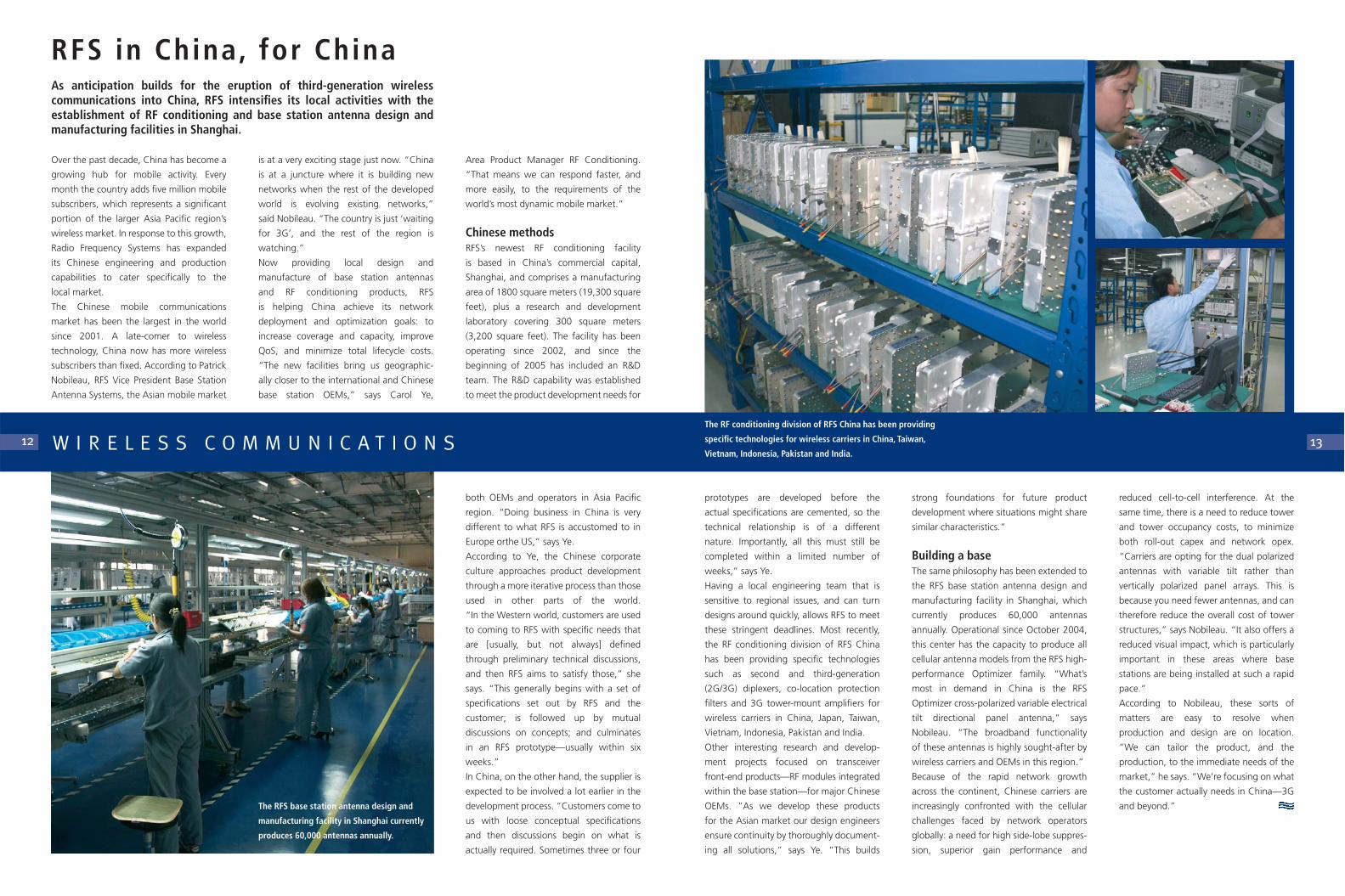
W I R E L E S S C O M M U N I C A T I O N SThe RF conditioning division of RFS China has been providing
specific technologies for wireless carriers in China, Taiwan,
Vietnam, Indonesia, Pakistan and India.
The RFS base station antenna design and
manufacturing facility in Shanghai currently
produces 60,000 antennas annually.

RF filters with sharp selectivity responses.
However, says Kiesling, the situation in
the United States is about to get very
interesting with the planned 2006 auction
of spectrum in the 1.7 and 2.1-GHz bands,
and later the 2.4-GHz band, by the nation’s
Federal Communications Commission (FCC).
“There’s a very real possibility that carriers
adopting 2.1-GHz spectrum for UMTS
transmission will co-locate with existing
PCS services,” says Kiesling. “If the
antennas are positioned too closely
together on the tower, the third order
intermodulation harmonic created by the
two signals stands to fall in the vicinity
of the 1.7-GHz UMTS receive band.”
(See Figure 1)
The problem here is that the intermodula-
tion signal is likely to be significantly
stronger than the desired receive signals,
leading to problems with blocking and
receiver sensitivity. If the intermodulation
signal falls out of the UMTS receive band,
installation of a RF filter on the UMTS uplink
will mitigate these interfering signals.
However, if the interfering intermodulation
signal happens to fall in-band, the situation
becomes more challenging. Kiesling
suggests that the only recourse for carriers
may be to work together to better manage
frequencies. Equipment vendors will also
be under pressure to ensure their designs
minimize passive intermodulation sources.
Future outlookThis scenario is but one predicted issue
to arise from the assignment of new
spectrum in the US. “The point is that we
don’t know exactly what the outlook is for
the future,” Kiesling says. “Once you’ve
got five different technologies up on the
same tower, you need a certain level of
cooperation and shared knowledge in
order to determine which services will
cause interference to others.”
Kiesling adds that the issue is influenced
by a shifting culture in base station site
ownership: in the US, around 70 percent
of sites are now owned by independent
tower real-estate companies, as carriers
seek to release capital for deployment.
“The site owners don’t necessarily
come from a wireless background and they
don’t necessarily understand all the issues,”
he says.
It all boils down to the fact that someone
needs to take responsibility for how co-
located services interact with each other,
emphasizes Kiesling. In cases where RF
filtering is not an option, this may be as
simple as ensuring certain antennas are not
positioned too close together, or operating
at reduced power levels. The bottom line is
that some degree of care will need to be
taken to avoid trouble at the tower top.
The contemporary demand for communi-
cations mobility is undeniably putting
pressure on wireless spectrum. New
technologies and services—such as WiMAX
and mobile television—are joining
third-generation (3G) cell-based mobile
services in the jostle for bandwidth.
Spectrum regulators are having to assess—
and quickly—how best to reassign and
redeploy spectrum and services to
pave the way for future applications.
An added complexity is the concurrent
trend towards co-location of base station
sites. Premium sites are in high demand,
leading to physical congestion of tower
structures and rooftops, as more and more
antenna systems are deployed. What can
result, says David Kiesling, Radio Frequency
Systems Director Marketing and Technical
Services, Americas North, is a cocktail of
frequencies and technologies at the
tower top that interact with each other
in unpredictable ways—in many cases
causing significant interference and
degradation of services.
US spectrum auctionsAccording to Kiesling, a more widespread
understanding of potential interactions and
interference is required in order to minimize
the impact on quality of service. “There
have been scenarios where a particular
service has been operating successfully for
years, then is suddenly impacted by the
introduction of a new service to the same
site,” he says. “An example of this is
the co-location of 800-MHz CDMA
and GSM 900-MHz services in countries
such as Brazil, China and India.”
The CDMA/GSM co-location scenario is
now well documented, and the solution
has been proven to lie in the deployment of
services exhibit higher peak voltages than
analog services with equivalent power. It is
therefore beneficial if the planned digital
replacement for analog services is factored
into system design at the beginning.
It doesn’t cost much to consider extra
power and voltage handling when
specifying an antenna and feeder system.
Expanding combinersWhen it comes to expanding an existing
combiner chain, there needs at the very least
to be space available. Coaxial combiners—as
most often seen in Europe—can be
rearranged relatively easily to accommodate
new modules, providing there is enough
power and voltage handling in the final
stages. On the other hand, it is far more
difficult to insert channels into a high-power
directional waveguide combiner system; in
such systems, it is advisable to incorporate
‘blanking’ sections into the chain where
additional channels can be inserted later.
However, it is usually necessary to know the
specific channel beforehand, since channel
sequence is important.
Although it is difficult to predict exactly
what technologies are coming down the
track, it is certainly possible—and perhaps
advisable—to build-in extra capacity to
multi-channel broadcast systems with very
little up-front expenditure. At the very least,
broadcasters should consider what services
they plan to introduce in replacement of
analog services, in order to ensure the
system will support them.
coverage: how likely is it that future services
will have the same requirements as the
existing channels?
This question is particularly pertinent if
DVB-H services are to be considered. It is still
unclear as to whether DVB-H will be
driven by broadcasters or the mobile
telecommunications industry—or whether
these industries are headed towards
some form of convergence or cooperation.
Distribution models utilizing various
frequency bands have been developed by
both parties: some based around mobile
base stations, others based on central
broadcast sites supported by translator sites
in a manner similar to DTT.
The issue of which form of polarization will
provide the best reception for mobile
television handsets deserves further consid-
eration. In addition, determining optimum
coverage is the subject of an increasing
number of DVB-H trials around the
world. Nevertheless, if the polarization and
coverage requirements of DVB-H are the
same as existing DTT services, it is certainly
possible to use a common infrastructure.
From a system design perspective, the issues
of power handling, voltage capacity, and
whether the combiner chain is able to be
expanded, need to be considered for a
future-proof system. Broadband antennas
are available to cover the full UHF spectrum;
however, the number of channels that the
system can support is dependent on
the power and voltage characteristics.
Importantly, in multi-channel systems the
voltage ratings become critical, plus digital
As analog switch-off dates draw closer in
some parts of the world, the deployment of
digital terrestrial television (DTT) services is
entering a new stage. The focus is starting
to shift towards ‘life after analog’, and the
opportunities that will arise from the
released spectrum. One of the key issues
for broadcasters is the capacity of existing
multi-channel broadcast systems to incor-
porate whatever new services might be
introduced—including mobile television.
For those broadcasters deploying new
networks: how can those systems be future-
proofed?
Multi-channel systems, where multiple
analog and/or digital services are broadcast
simultaneously from a shared RF broadcast
infrastructure, are common across Europe
and rising in popularity elsewhere. Utilizing
broadband panel arrays and advanced
RF combining technology, such broadband
systems help minimize installation costs and
optimize site real-estate. With little extra
capital expenditure, decisions can be
made now that will make the addition
of future digital services—including
the emerging Digital Video Broadcasting-
Handheld (DVB-H)—easier and less costly.
The future-proof systemA number of important factors need to be
considered when designing a future-proof
system. From a practical perspective, there is
the consideration of signal polarization and
14 15B R O A D C A S T
Broadband RF now,mobi le TV laterImpending analog switch-off will provide plenty of options for broadcasters seeking to utilize the releasedspectrum; but how can RF systems be made future-proof to accommodate the new services?
W I R E L E S S C O M M U N I C A T I O N S
Trouble at the tower topAs the FCC auctions wireless spectrum for future services in the US, thecocktail of co-located technologies and frequencies at the tower top couldinteract with each other in unpredictable ways—spawning unprecedentedinterference challenges.
Figure 1: The UMTS/PCS co-location challenge

taken the time to analyze the trends
and identify a series of products to
maximize these fast-maturing networks.”
Recently, both carriers have seen the
value of using RFS’s range of high-
performance boosters from its RF
conditioning family of products. According
to Rivkina, DCC/Astelit, being a new
carrier with a young network, has seen the
need for boosters and tower-mount
amplifiers to increase its network capacity.
“Our customers rely on us to keep
them abreast of new and interesting
technologies. It’s a very open and trusting
relationship,” says Rivkina.
RFS regularly delivers presentations on new
and next-generation technologies to the
Ukrainian carriers, keeping them up to
date with progress in the industry. RFS
also holds annual installation training
courses for the carriers’ subcontractors.
“That’s what sets RFS apart from the
rest, we go to the source of the issue
and work out from there—such as
providing training to our customers’
installation service providers,” says Rivkina.
More than just caring, RFS has the
advantage of foresight. “Being a global
organization we have gone through
all stages of the wireless development
lifecycle. We’ve found that our experience
in Eastern Europe and the rest of the
wireless world provides an important
foundation for our work in Ukraine.”
Over the coming five years, the Ukrainian
carriers are expected to continue increasing
both coverage and capacity of their
GSM networks. Next on the cards is
universal mobile telecommunications
service (UMTS), with the first 3G license to
be awarded very soon to the incumbent
fixed line operator, Ukrtelecom, a new
player in the mobile market. The company
plans to launch commercial UMTS services
by end-2006. “Just as we’ve been there all
along for the development of the country’s
2G, we’ll be there also to facilitate Ukraine’s
transition into 3G,” says Rivkina.
“Based on the reliability of the RFS trans-
mission lines, the Ukrainian carriers are now
starting to look into other RFS technologies
to modernize their networks,” says Rivkina.
Capped capacityOf particular interest to the Ukrainian
mobile sector in its current evolutionary
stage is RFS’s suite of network optimization
products. “Both UMC and Kyivstar are
continually rolling out new networks and
optimizing existing ones. Yet, as the
subscriber numbers increase relentlessly,
the demand for capacity remains the
driving factor,” says Rivkina. “We’ve
In order to keep abreast of the require-
ments of the local operators, RFS
operates in the Ukraine through three
sales partners: Radiochastotnyie Sistemyi
Ukraine, Stankotechimport and Actek C.
These partners act as RFS’s ‘ears on the
ground’, although RFS also maintains a
tight focus on the region. “Ukraine is a very
important country for us,” says Rivkina.
“We have an area manager completely
dedicated to looking after RFS customers in
Ukraine, Belarus and Moldova. We also
have two customer service coordinators
providing technical and commercial
informational support to RFS customers in
Russia and CIS, as well as processing the
orders. From a global RFS perspective,
Ukraine is an important market, and that’s
why the RFS name is so established here.”
A large portion of RFS’s success in the
region is due to its ability to meet Ukraine’s
uniquely short delivery time requirements.
In a country that from 2004 to 2005
increased its mobile subscriber base by 110
percent, fast delivery is of the utmost
importance. “RFS has manufacturing
facilities in Balabanovo, near Moscow, and
also in France, Denmark, Germany and so
on. So, by leveraging this global framework
we can meet any order within the shortest
delivery time,” says Rivkina.
An important element of the spectrum of
solutions provided by RFS to the Ukrainian
wireless communication sector is CELLFLEX
foam-dielectric coaxial cable and acces-
sories. The popular and high-performance
RFS feeder cable forms the backbone
to the RF distribution of both UMC and
Kyivstar—and more recently DCC/Astelit.
digital age,” says Rivkina. “Now we're
happy to be assisting all three carriers in
Ukraine's dynamic telecommunications
market.”
Reputation for reliabilityNine years of collaboration with the
Ukrainian wireless carriers has given RFS a
reputation for first-class quality and short
delivery times. “In this region—Ukraine,
Belarus and Moldova—trust is a very
important part of business, and RFS, with
its local sales partners, has proven itself over
and over again,” says Rivkina.
(UMC) and Kyivstar—have continued
to maintain a duopoly now representing
98 percent of Ukraine’s mobile subscriptions.
Originally the leading operator, UMC was
forced in mid-2001 to stop accepting
pre-paid subscriptions for a period of
three months due to network capacity
problems. This paved the way for Kyivstar
to take a strong position in the market.
Since then, despite fierce competition
between the two, both GSM carriers
have been on par, but their overall
dominance has been almost unassailable.
Other carriers have since looked towards
the Ukrainian wireless industry, although
their success has been limited and, in most
cases, transitory. The first to really make its
mark in the Ukrainian wireless market
has been Turkish Turkcell-backed Digital
Cellular Communication of Ukraine
(DCC)/Astelit, with its ‘Life’ network.
Launched in 2005, DCC/Astelit is the
newest GSM carrier in Ukraine and is
currently deploying an aggressive network
roll-out incorporating 2.5 generation
technologies. Determined to find a niche
within this rapidly expanding sector,
DCC/Astelit has been marketing its
fashionable ‘Life’ brand, which targets
students and young adults. The success of
the ‘Life’ network is all the more significant
in light of Turkcell’s first Ukrainian wireless
venture in 2001—the ‘Novacell’ network—
which folded within two years.
According to Natalia Rivkina, RFS Regional
Sales Manager, DCC/Astelit is a very new
carrier in the Ukrainian wireless market.
“RFS has been involved with UMC and
Kyivstar since the beginning of Ukraine's
The first form of wireless communication in
Ukraine was a symbolic ‘human chain’
formed by half a million Ukrainians joining
hands from the capital Kiev, to Lviv in the
west. This occurred on January 22, 1990,
and stretched over 500 kilometers
(310 miles). The act was in commemoration
of the anniversary of the proclamation of
Ukrainian independence in 1918.
Ending in 1920, the period of indepen-
dence was short-lived, and it wasn’t until
the dissolution of the USSR in 1991, that
Ukraine finally regained independence.
With its freedom, the country also took
on a series of challenges to begin
upgrading its telecommunications sector.
The national telecommunications develop-
ment plan led first to the launch of analog
mobile telephony (using the Nordic Mobile
Telephone (NMT) standard in 1993.
The launch of global system for mobile
communications (GSM) digital networks in
the 900- and 1800-MHz bands followed
closely in 1996. This is also the year that
Radio Frequency Systems began to assist in
the country’s roll-out of wireless networks.
By 2001, two main GSM carriers had
secured the majority of the mobile market,
seizing more than 90 percent of the
subscriber base between them.
Three’s a crowdUkraine’s total mobile subscriber base has
increased from just two million in 2001, to
more than 20 million in 2005, equating to
a mobile penetration increase from four
percent to nearly 50 percent in just
four years. Over this time, the two main
carriers—Ukrainian Mobile Communications
17
Ukraine spreads the wireless wordOne of the fastest growing wireless markets in the world, Ukraine leans heavily on RFS technologies as the foundation for its nationwide RF networks.
16
The Mikhailovski
Cathedral in Kiev
R E G I O N A L F O C U SThe Dnepr River is the Ukraine’s most significant
river, and—at 2300 kilometers (1430 miles)
long—one of Europe’s longest.
Ukraine’s Kievo-
Pecherskaya Lavra in Kiev
is a center of pilgrimage
for Orthodox Christians
from all over the world.
data transfer, Powles and his team are
steadily upgrading analog microwave
networks to digital.
“We have standardized on RFS as a
supplier of microwave antennas, feed
lines and connectors,” said Powles. “This
has been driven by the high standard
of manufacture, ease of assembly and
maintenance, and overall reliability. Our
riggers requested we make the transition to
RFS. We feel RFS is a better product, and
the fact that it is incorporated into the
WSCA agreement has made things that
much easier.”
Asad Zoberi, RFS Area Product Manager for
microwave antenna systems, explained the
WSCA contract for supply of public safety
communications equipment is available to
all government agencies, sub-agencies and
political non-profit organizations within
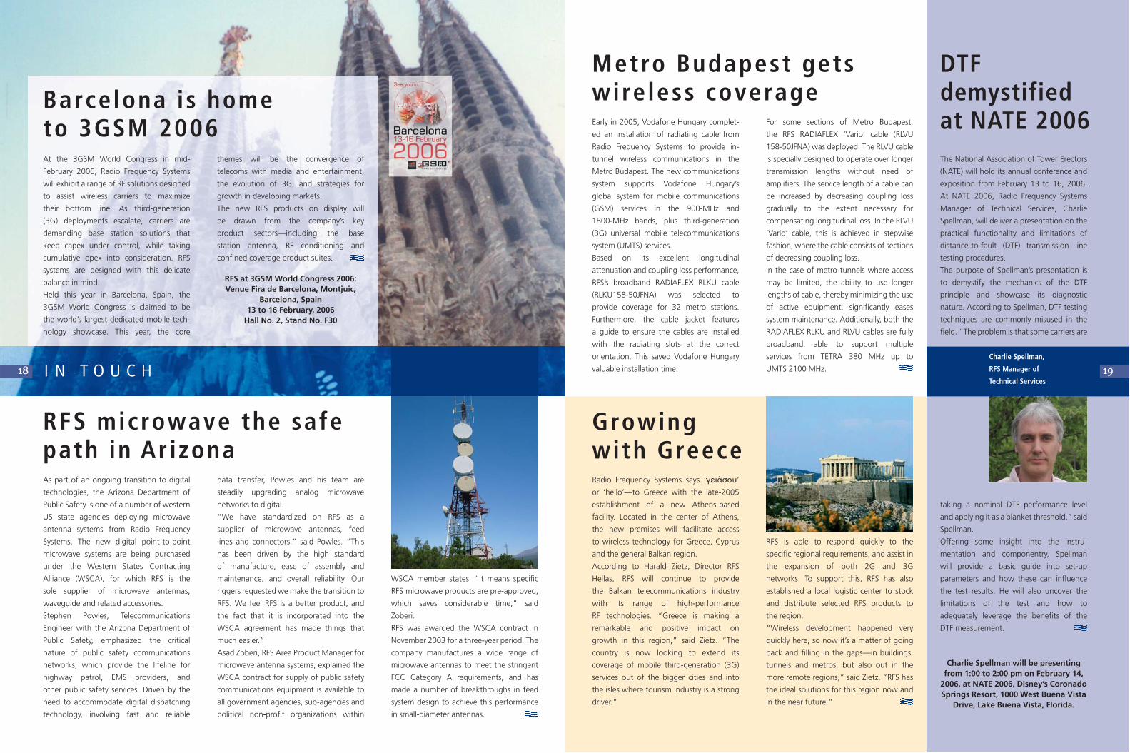
The National Association of Tower Erectors
(NATE) will hold its annual conference and
exposition from February 13 to 16, 2006.
At NATE 2006, Radio Frequency Systems
Manager of Technical Services, Charlie
Spellman, will deliver a presentation on the
practical functionality and limitations of
distance-to-fault (DTF) transmission line
testing procedures.
The purpose of Spellman’s presentation is
to demystify the mechanics of the DTF
principle and showcase its diagnostic
nature. According to Spellman, DTF testing
techniques are commonly misused in the
field. “The problem is that some carriers are
taking a nominal DTF performance level
and applying it as a blanket threshold,” said
Spellman.
Offering some insight into the instru-
mentation and componentry, Spellman
will provide a basic guide into set-up
parameters and how these can influence
the test results. He will also uncover the
limitations of the test and how to
adequately leverage the benefits of the
DTF measurement.
Charlie Spellman will be presentingfrom 1:00 to 2:00 pm on February 14,
2006, at NATE 2006, Disney’s CoronadoSprings Resort, 1000 West Buena Vista
Drive, Lake Buena Vista, Florida.
RFS is able to respond quickly to the
specific regional requirements, and assist in
the expansion of both 2G and 3G
networks. To support this, RFS has also
established a local logistic center to stock
and distribute selected RFS products to
the region.
“Wireless development happened very
quickly here, so now it’s a matter of going
back and filling in the gaps—in buildings,
tunnels and metros, but also out in the
more remote regions,” said Zietz. “RFS has
the ideal solutions for this region now and
in the near future.”
themes will be the convergence of
telecoms with media and entertainment,
the evolution of 3G, and strategies for
growth in developing markets.
The new RFS products on display will
be drawn from the company’s key
product sectors—including the base
station antenna, RF conditioning and
confined coverage product suites.
RFS at 3GSM World Congress 2006:Venue Fira de Barcelona, Montjuic,
Barcelona, Spain13 to 16 February, 2006
Hall No. 2, Stand No. F30
At the 3GSM World Congress in mid-
February 2006, Radio Frequency Systems
will exhibit a range of RF solutions designed
to assist wireless carriers to maximize
their bottom line. As third-generation
(3G) deployments escalate, carriers are
demanding base station solutions that
keep capex under control, while taking
cumulative opex into consideration. RFS
systems are designed with this delicate
balance in mind.
Held this year in Barcelona, Spain, the
3GSM World Congress is claimed to be
the world’s largest dedicated mobile tech-
nology showcase. This year, the core
18
Radio Frequency Systems says ‘γειάσ�υ’
or ‘hello’—to Greece with the late-2005
establishment of a new Athens-based
facility. Located in the center of Athens,
the new premises will facilitate access
to wireless technology for Greece, Cyprus
and the general Balkan region.
According to Harald Zietz, Director RFS
Hellas, RFS will continue to provide
the Balkan telecommunications industry
with its range of high-performance
RF technologies. “Greece is making a
remarkable and positive impact on
growth in this region,” said Zietz. “The
country is now looking to extend its
coverage of mobile third-generation (3G)
services out of the bigger cities and into
the isles where tourism industry is a strong
driver.”
I N T O U C H
Barcelona is home to 3GSM 2006
Growingwith Greece
RFS microwave the safepath in Ar izonaAs part of an ongoing transition to digital
technologies, the Arizona Department of
Public Safety is one of a number of western
US state agencies deploying microwave
antenna systems from Radio Frequency
Systems. The new digital point-to-point
microwave systems are being purchased
under the Western States Contracting
Alliance (WSCA), for which RFS is the
sole supplier of microwave antennas,
waveguide and related accessories.
Stephen Powles, Telecommunications
Engineer with the Arizona Department of
Public Safety, emphasized the critical
nature of public safety communications
networks, which provide the lifeline for
highway patrol, EMS providers, and
other public safety services. Driven by the
need to accommodate digital dispatching
technology, involving fast and reliable
Early in 2005, Vodafone Hungary complet-
ed an installation of radiating cable from
Radio Frequency Systems to provide in-
tunnel wireless communications in the
Metro Budapest. The new communications
system supports Vodafone Hungary’s
global system for mobile communications
(GSM) services in the 900-MHz and
1800-MHz bands, plus third-generation
(3G) universal mobile telecommunications
system (UMTS) services.
Based on its excellent longitudinal
attenuation and coupling loss performance,
RFS’s broadband RADIAFLEX RLKU cable
(RLKU158-50JFNA) was selected to
provide coverage for 32 metro stations.
Furthermore, the cable jacket features
a guide to ensure the cables are installed
with the radiating slots at the correct
orientation. This saved Vodafone Hungary
valuable installation time. 19
Metro Budapest getswireless coverage
WSCA member states. “It means specific
RFS microwave products are pre-approved,
which saves considerable time,” said
Zoberi.
RFS was awarded the WSCA contract in
November 2003 for a three-year period. The
company manufactures a wide range of
microwave antennas to meet the stringent
FCC Category A requirements, and has
made a number of breakthroughs in feed
system design to achieve this performance
in small-diameter antennas.
DTF demystified at NATE 2006
Charlie Spellman,
RFS Manager of
Technical Services
For some sections of Metro Budapest,
the RFS RADIAFLEX ‘Vario’ cable (RLVU
158-50JFNA) was deployed. The RLVU cable
is specially designed to operate over longer
transmission lengths without need of
amplifiers. The service length of a cable can
be increased by decreasing coupling loss
gradually to the extent necessary for
compensating longitudinal loss. In the RLVU
‘Vario’ cable, this is achieved in stepwise
fashion, where the cable consists of sections
of decreasing coupling loss.
In the case of metro tunnels where access
may be limited, the ability to use longer
lengths of cable, thereby minimizing the use
of active equipment, significantly eases
system maintenance. Additionally, both the
RADIAFLEX RLKU and RLVU cables are fully
broadband, able to support multiple
services from TETRA 380 MHz up to
UMTS 2100 MHz.


