
Dr. Peter M. Suh Aerospace Engineer
Flight Controls and DynamicsNASA Armstrong Flight Research
Center
Rapid State Space Modeling Tool for Rectangular Wing Aeroservoelastic
Studies
12/17/2014 1
Dr. Dimitri N. MavrisAerospace Systems Design
Laboratory DirectorGeorgia Institute of Technology
Dr. Howard J. ConyersAerospace Technologist
Engineering and Test DirectorateNASA Stennis Space Center
AIAA Modeling and Simulation Technologies Conference, Jan 5-9, 2015
https://ntrs.nasa.gov/search.jsp?R=20150000848 2018-09-06T20:36:41+00:00Z

Outline
• Overview & Motivation
• Aeroservoelastic tool • Verification and
Validation studies• State Space Model
Development and Results
• Conclusions
12/17/2014 2AIAA Modeling and Simulation Technologies Conference, Jan 5-9, 2015

Overview & Motivation• Overview– Presentation of computational and experimental
results from a recently developed rectangular wing aeroservoelastic modeling tool
• Motivation– Compare tool to independently published work2
– To support rapid investigation of aeroservoelasticphenomena in a medium-fidelity tool• Also novel sensors such as fiber optics
– Provide a rapid aeroservoelastic design platform which can serve students of aeroservoelasticity
12/17/2014 3AIAA Modeling and Simulation Technologies Conference, Jan 5-9, 2015
2SConyers, H. J., Dowell, E. H., and Hall, K. C., Aeroservoelastic Studies of a Rectangular Wing with a Hole: Correlation of Theory and Experiment,” 2010 Aerospace Systems Conference

Background
• In previous work1, tool used to model a clamped wing structure with two control surfaces and fiber optic sensor feedback used for flutter suppression
12/17/2014 4AIAA Modeling and Simulation Technologies Conference, Jan 5-9, 2015
Three fibers with Bragg gratings spaced every ½ inch
Wing Root
1Suh, P. M., and Mavris, D. N., Modal Filtering for Control of Flexible Aircraft, AIAA 2013-1741
Computational Wing Model Active Flutter Suppression
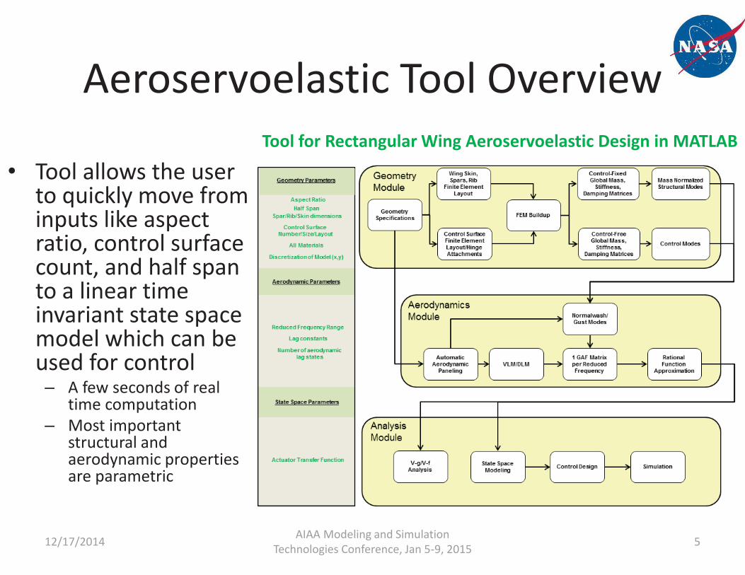
Aeroservoelastic Tool Overview
12/17/2014 5AIAA Modeling and Simulation Technologies Conference, Jan 5-9, 2015
• Tool allows the user to quickly move from inputs like aspect ratio, control surface count, and half span to a linear time invariant state space model which can be used for control– A few seconds of real
time computation– Most important
structural and aerodynamic properties are parametric
Tool for Rectangular Wing Aeroservoelastic Design in MATLAB
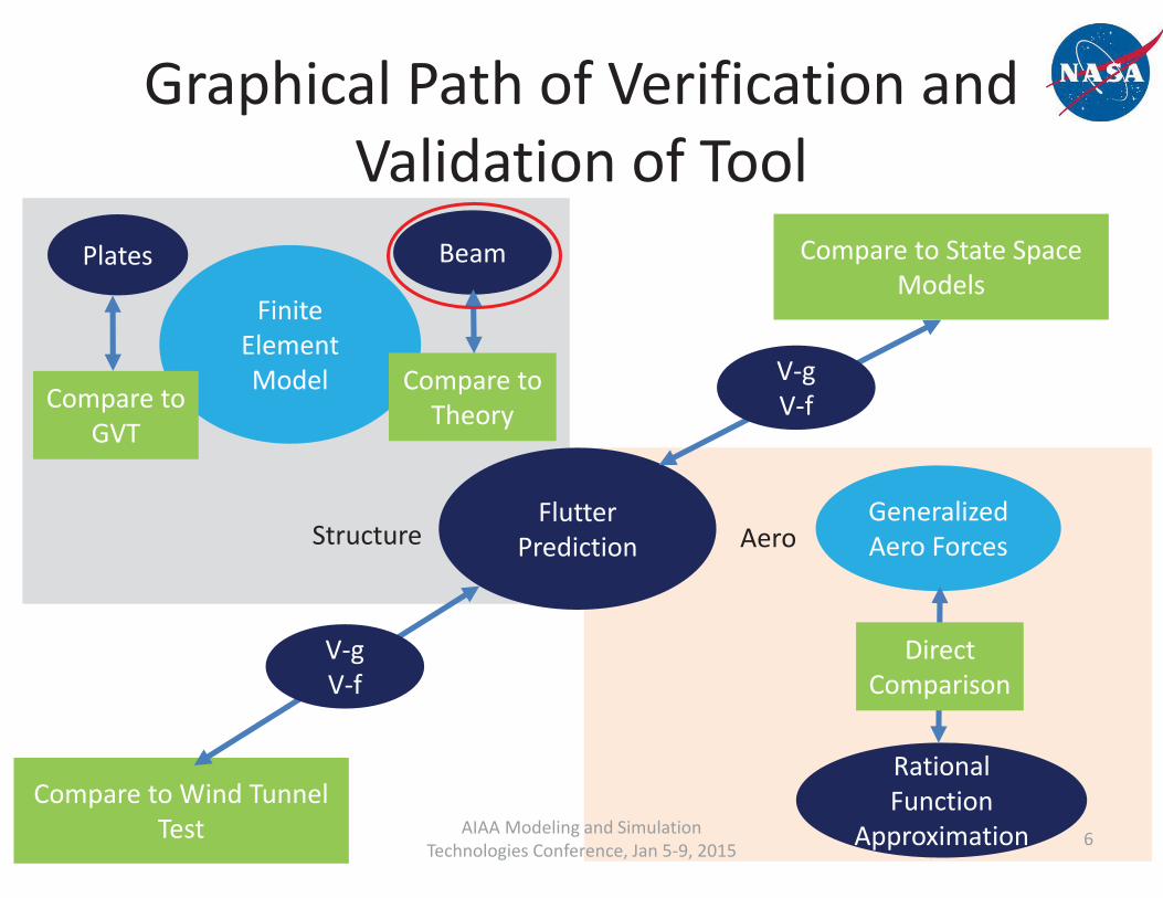
Graphical Path of Verification and Validation of Tool
12/17/2014 6AIAA Modeling and Simulation Technologies Conference, Jan 5-9, 2015
Finite ElementModel
Generalized Aero Forces
BeamPlates
Rational Function
Approximation
Flutter Prediction
Compare to TheoryCompare to
GVT
Compare to Wind Tunnel Test
DirectComparison
Structure Aero
V-gV-f
Compare to State Space Models
V-gV-f

Beam Model Verification• Beams used to model wing structure
– FEM with 30 elements compared to theory show good matches in bending and torsion
12/17/2014 7AIAA Modeling and Simulation Technologies Conference, Jan 5-9, 2015
Cantilever Theory versus FEM Beam Model: Deflection and Twist

Graphical Path of Verification and Validation of Tool
12/17/2014 8AIAA Modeling and Simulation Technologies Conference, Jan 5-9, 2015
Finite ElementModel
Generalized Aero Forces
BeamPlates
Rational Function
Approximation
Flutter Prediction
Compare to TheoryCompare to
GVT
Compare to Wind Tunnel Test
DirectComparison
Structure Aero
V-gV-f
Compare to State Space Models
V-gV-f

Plate FEM Validation• Ground Vibration Test (GVT) on a
article used for validation of plate FEM
• Plate FEM Discretized with 16x16 12 DOF isotropic plate elements
• Experiment shows good correlation with ANSYS and tool
12/17/2014 9AIAA Modeling and Simulation Technologies Conference, Jan 5-9, 2015
Experimental Data2
clamped
GVT on Article (with a hole for a different test) Computational Model
16x16 elements
2SConyers, H. J., Dowell, E. H., and Hall, K. C., Aeroservoelastic Studies of a Rectangular Wing with a Hole: Correlation of Theory and Experiment,” 2010 Aerospace Systems Conference

Graphical Path of Verification and Validation of Tool
12/17/2014 10AIAA Modeling and Simulation Technologies Conference, Jan 5-9, 2015
Finite ElementModel
Generalized Aero Forces
BeamPlates
Rational Function
Approximation
Flutter Prediction
Compare to TheoryCompare to
GVT
Compare to Wind Tunnel Test
DirectComparison
Structure Aero
V-gV-f
Compare to State Space Models
V-gV-f
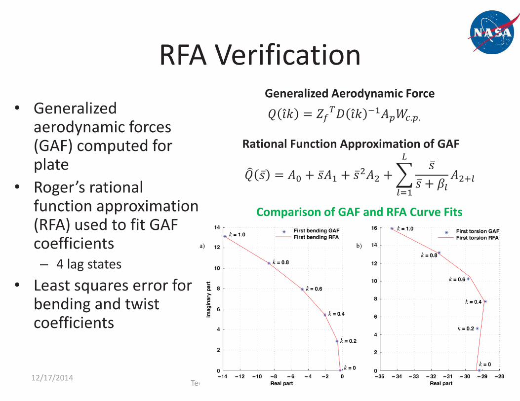
RFA Verification• Generalized
aerodynamic forces (GAF) computed for plate
• Roger’s rational function approximation (RFA) used to fit GAF coefficients– 4 lag states
• Least squares error for bending and twist coefficients
12/17/2014 11AIAA Modeling and Simulation Technologies Conference, Jan 5-9, 2015
Generalized Aerodynamic Force
Rational Function Approximation of GAF
Comparison of GAF and RFA Curve Fits

V-g Analysis using RFA• The test plate article flutter speed was predicted to be 19.9
m/s– traditional bending/torsion flutter mode
12/17/2014 12AIAA Modeling and Simulation Technologies Conference, Jan 5-9, 2015
V-g Analysis on Computational Plate Article
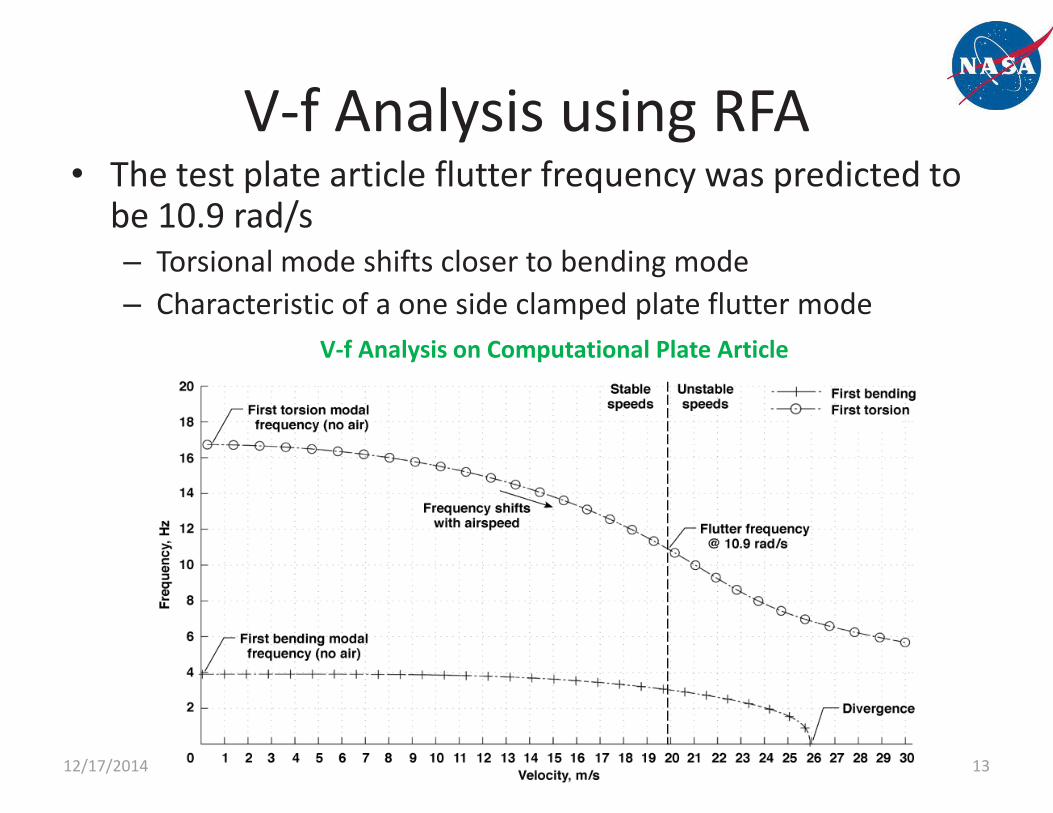
V-f Analysis using RFA• The test plate article flutter frequency was predicted to
be 10.9 rad/s– Torsional mode shifts closer to bending mode– Characteristic of a one side clamped plate flutter mode
12/17/2014 13AIAA Modeling and Simulation Technologies Conference, Jan 5-9, 2015
V-f Analysis on Computational Plate Article

Graphical Path of Verification and Validation of Tool
12/17/2014 14AIAA Modeling and Simulation Technologies Conference, Jan 5-9, 2015
Finite ElementModel
Generalized Aero Forces
BeamPlates
Rational Function
Approximation
Flutter Prediction
Compare to TheoryCompare to
GVT
Compare to Wind Tunnel Test
DirectComparison
Structure Aero
V-gV-f
Compare to State Space Models
V-gV-f

Flutter Validation Experimental Study• A wind tunnel investigation was
completed at Duke University in previous work– Tool flutter speed shows good
correlation with Conyers et al.’s flutter code• Differences may be due to use of more
aero panels in the tool– Wind tunnel results were comparably
close
12/17/2014 15AIAA Modeling and Simulation Technologies Conference, Jan 5-9, 2015
Experimental Data2
Configuration for Wind Tunnel Test at Duke(different article shown than flat plate)
2SConyers, H. J., Dowell, E. H., and Hall, K. C., Aeroservoelastic Studies of a Rectangular Wing with a Hole: Correlation of Theory and Experiment,” 2010 Aerospace Systems Conference

Graphical Path of Verification and Validation of Tool
12/17/2014 16AIAA Modeling and Simulation Technologies Conference, Jan 5-9, 2015
Finite ElementModel
Generalized Aero Forces
BeamPlates
Rational Function
Approximation
Flutter Prediction
Compare to TheoryCompare to
GVT
Compare to Wind Tunnel Test
DirectComparison
Structure Aero
V-gV-f
Compare to State Space Models
V-gV-f

Compare to each other
State Space Model Verification• We verify that the state space models
correlate with what was predicted from the V-g and V-f analyses
12/17/2014 17AIAA Modeling and Simulation Technologies Conference, Jan 5-9, 2015
V-gV-f
Bode Poles
Time history
Gust Response

State Space Model Architecture• Components of state space models
– FEM mass, stiffness, damping and modal matrices – Rational function approximation coefficients – Actuator dynamic models – Flight condition
12/17/2014 18AIAA Modeling and Simulation Technologies Conference, Jan 5-9, 2015
State Space Model Architecture Modal displacement
Modal velocity
Aero lag states
Gust statesControl states
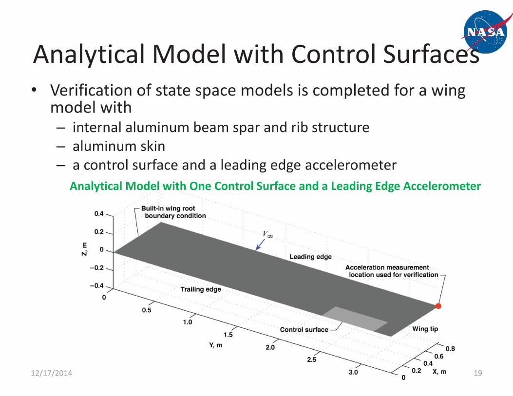
Analytical Model with Control Surfaces• Verification of state space models is completed for a wing
model with– internal aluminum beam spar and rib structure– aluminum skin– a control surface and a leading edge accelerometer
12/17/2014 19AIAA Modeling and Simulation Technologies Conference, Jan 5-9, 2015
Analytical Model with One Control Surface and a Leading Edge Accelerometer

Actuator Dynamics
12/17/2014 20AIAA Modeling and Simulation Technologies Conference, Jan 5-9, 2015
• Actuators are modeled as 3rd order transfer functions– 1st order command lag– 2nd order actuator dynamics
Actuator Model with and without command lag

Analytical Wing Mode Shapes• Mass normalized mode shapes are computed with high
torsional spring stiffness in connected control surfaces• Control modes are computed with low torsional spring
stiffness and a prescribed 1 deg. rotation boundary condition
12/17/2014 21AIAA Modeling and Simulation Technologies Conference, Jan 5-9, 2015
Analytical Wing Modal Analysis

Compare to each other
State Space Model Verification• We verify that the state space models
correlate with what was predicted from the V-g and V-f analyses
12/17/2014 22AIAA Modeling and Simulation Technologies Conference, Jan 5-9, 2015
V-gV-f
Bode Poles
Time history
Gust Response

V-g Analysis with RFA
• V-g analysis of wing shows a traditional bending/torsion flutter mode appearing at 76.5 m/s
12/17/2014 23AIAA Modeling and Simulation Technologies Conference, Jan 5-9, 2015
V-g Analysis of Analytical Wing Model
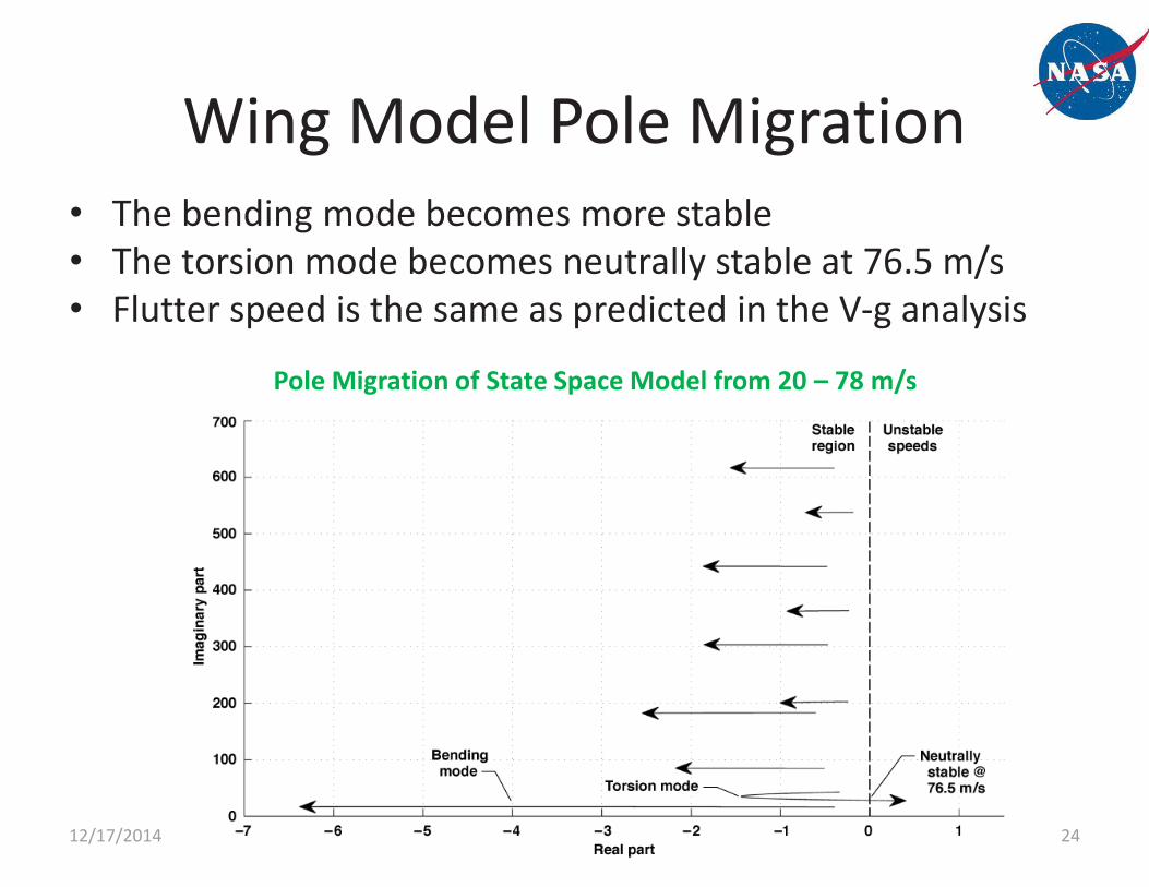
Wing Model Pole Migration• The bending mode becomes more stable• The torsion mode becomes neutrally stable at 76.5 m/s• Flutter speed is the same as predicted in the V-g analysis
12/17/2014 24AIAA Modeling and Simulation Technologies Conference, Jan 5-9, 2015
Pole Migration of State Space Model from 20 – 78 m/s

Compare to each other
State Space Model Verification• We verify that the state space models
correlate with what was predicted from the V-g and V-f analyses
12/17/2014 25AIAA Modeling and Simulation Technologies Conference, Jan 5-9, 2015
V-gV-f
Bode Poles
Time history
Gust Response
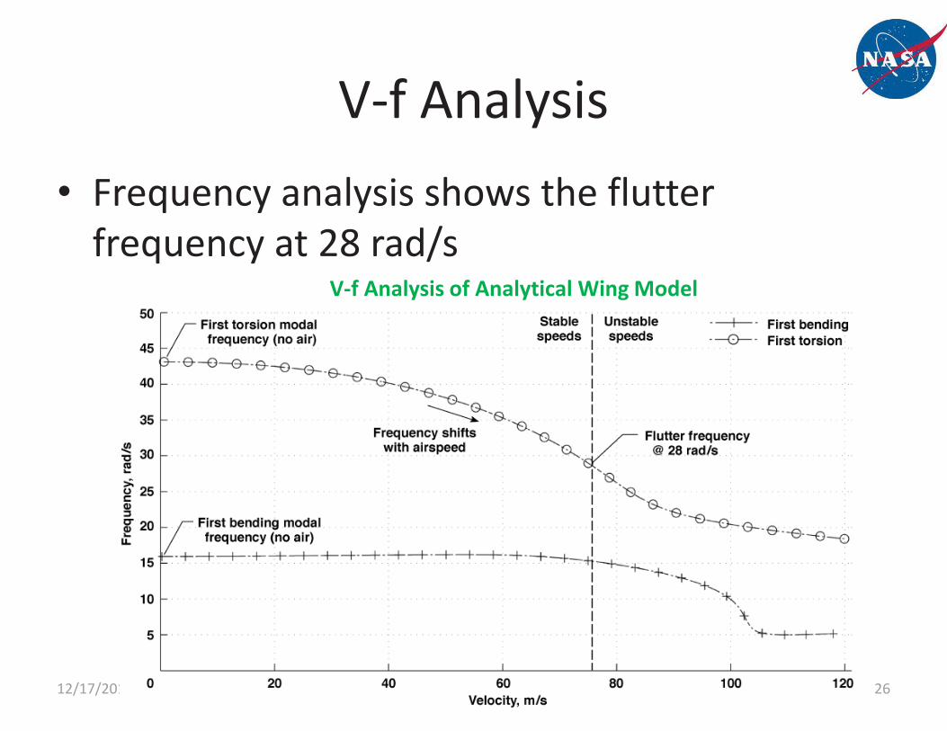
V-f Analysis• Frequency analysis shows the flutter
frequency at 28 rad/s
12/17/2014 26AIAA Modeling and Simulation Technologies Conference, Jan 5-9, 2015
V-f Analysis of Analytical Wing Model

Bode Plot of State Space Model• At speed below flutter speed, amplitudes of two distinct modes visible• At flutter speed only flutter mode is visible• Frequency is the same as predicted from the V-f analysis
12/17/2014 27AIAA Modeling and Simulation Technologies Conference, Jan 5-9, 2015
Bode Plot of Surface to Leading Edge Accelerometer

Compare to each other
State Space Model Verification• We verify that the state space models
correlate with what was predicted from the V-g and V-f analyses
12/17/2014 28AIAA Modeling and Simulation Technologies Conference, Jan 5-9, 2015
V-gV-f
Bode Poles
Time history
Gust Response

Impulse to State Space Model• Flutter is apparent in model designed past flutter speed
– Divergent oscillatory• Model at lower speed is damped after impulse
12/17/2014 29AIAA Modeling and Simulation Technologies Conference, Jan 5-9, 2015
Effects of higher modes are visible before flutter dominates

Compare to each other
State Space Model Verification• We verify that the state space models
correlate with what was predicted from the V-g and V-f analyses
12/17/2014 30AIAA Modeling and Simulation Technologies Conference, Jan 5-9, 2015
V-gV-f
Bode Poles
Time history
Gust Response

1-cos Gust Model
12/17/2014 31AIAA Modeling and Simulation Technologies Conference, Jan 5-9, 2015
• Gust inputs to structure are designed with gust modes and 1-cos gust input structure
Gust velocity
Gust acceleration
Gust frequency
Gust mode approximation1-cos Gust Input Model

Gust Input to State Space Model• The response of wing to 1-cos gust is expected– Low frequency gust response and high frequency
oscillations from flutter are seen to be superimposed
12/17/2014 32AIAA Modeling and Simulation Technologies Conference, Jan 5-9, 2015
Bode Plot of Surface to Leading Edge Accelerometer

Conclusions
• Several first step verification and validation studies were presented for a new aeroservoelastic tool
• More verification and validation is needed to assess the state space models including– An experimental flutter test and active flutter
suppression • This work further supports independent flutter
analysis conducted by Dr. Conyers in his dissertation
12/17/2014 33AIAA Modeling and Simulation Technologies Conference, Jan 5-9, 2015
Future Work
• Improvements will be made to include rigid body modes in the tool
• Input structure will be made more user friendly
• Would like to look into transitioning to use as an open tool for students
12/17/2014 34AIAA Modeling and Simulation Technologies Conference, Jan 5-9, 2015

Questions?
12/17/2014 35AIAA Modeling and Simulation Technologies Conference, Jan 5-9, 2015


