INSTRUCTIONS
REFLECTEDFLUORESCENCE
SYSTEMFOR CKX41
A X 7 3 8 9
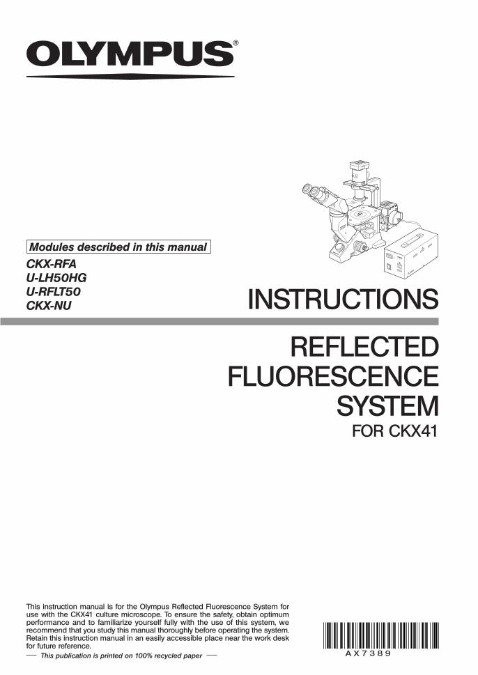
This instruction manual is for the Olympus Reflected Fluorescence System foruse with the CKX41 culture microscope. To ensure the safety, obtain optimumperformance and to familiarize yourself fully with the use of this system, werecommend that you study this manual thoroughly before operating the system.Retain this instruction manual in an easily accessible place near the work deskfor future reference.
Modules described in this manual
CKX-RFAU-LH50HGU-RFLT50CKX-NU
This publication is printed on 100% recycled paper

CONTENTS
To let the reflected fluorescence system manifest its full performance, it is critical that youassemble and adjust the system properly. If you want to assemble the system yourself, readChapter 7, “ASSEMBLY” (pages 21 to 28) first.
IMPORTANT - Be sure to read this first for safe use of the equipment. -
1 NOMENCLATURE
1 General Precautions for Observation
4 Turning On the Mercury Burner
6 Centering the Field Iris Diaphragm
3 Applicable Fluorescence Objectives
5 Centering the Mercury Burner
1-3
9-17
21-28
20
5 TROUBLESHOOTING GUIDE 18,19
7 Switching the Filter Slider
2 CONTROLS OF EACH MODULE
3 SUMMARY OF REFLECTED FLUORESCENCE OBSERVATION PROCEDURE
4 USING THE CONTROLS
4
5,6
7,8
6 SPECIFICATIONS
7 ASSEMBLY
8 U-EXCITATION FILTER SET CKX-NU (OPTIONAL) 29
REFLECTED FLUORESCENCE SYSTEM FOR CKX41
2 Selecting the Reflected Light Fluorescent Mirror
PROPER SELECTION OF THE POWER SUPPLY CORD ................................................... 30,31
1
IMPORTANT
The reflected fluorescence system is designed to be mounted on the CKX41 culture microscopeto enable the transmitted light observation and B/G-excited (U-excitation optionally available)fluorescence observation by switching them using a slider.
SAFETY PRECAUTIONS
1 . Make sure that the main switch of the power supply unit is set to “ ” (OFF) before connecting thepower cord to the AC outlet.
2 . The power supply unit contains high-voltage components. Never attempt to disassembly the unit, oryou may run the risk of electric shock.
3 . Always be sure to ground (earth) the equipment. Otherwise, Olympus will no longer warrant theelectrical safety of the equipment.
4 . The reflected fluorescence system should be installed on a flat surface so that the ventilation openingon the bottom panel is not blocked.Do not install the system on a surface which is soft or which may collapse under the weight of themicroscope, for the subsequent blockage of the bottom panel ventilation opening could create a firehazard.
5 . The high-pressure mercury burner used should be the HBO50W/AC (OSRAM) or CS50W4 (PHILIPS). 6 . Before opening the lamp housing for replacement of the burner or any other internal part, set the
mains witch to “ ” (OFF), unplug the lamp housing connecting cord from the outlet connector on thepower supply unit, and wait 10 minutes or more until the lamp housing cools down.
7 . Do not open the lamp housing while it is turned on or for at least 10 minutes after it has been turnedoff. Lamp housing parts are extremely hot and cause burns if touched (see page 13).
8 . Do not remove the lamp housing while the burner is lit. Also, do not turn the burner on while the lamp housing is removed.
9 . Do not install the lamp housing upside down or at an angle.The lamp housing surface becomes very hot during operation, so ensure that there is ample freespace around the lamp housing, especially above and below.
10 . If the microscope power cord comes in contact with the lamp housing or its surroundings, the cordmay melt and subsequently cause electric shock. Be sure to position the power cord at a safedistance from the lamp housing.
11 . A used mercury burner should be disposed of in compliance with the ordinances or regulations ofyour national or local government.
12 . To replace the lithium battery (for the hour counter) built into the power supply unit, consult Olympus.As the power supply unit incorporates a lithium battery, it should be disposed of in the same way as aused mercury burner, i.e., in compliance with the ordinances or regulations of your national or localgovernment.
13 . Before placement of the dust cover for protection after operation, wait until the lamp housing coolsdown sufficiently and unplug the power cord.
2
REFLECTED FLUORESCENCE SYSTEM FOR CKX41
Safety Symbols
I\
The following symbols are found on the system. Study the meaning of the symbols and always use theequipment in the safest possible manner.
Symbol Explanation
Indicates that the surface becomes hot, and should not be touched withbare hands.
Before use, carefully read the instruction manual. Improper use could resultin personal injury to the user and/or damage to the equipment.
Indicates a potential fire hazard; when replacing fuses, be sure that thereplacement fuses are of the specified rating.
Indicates that the main switch is ON.
Indicates that the main switch is OFF.
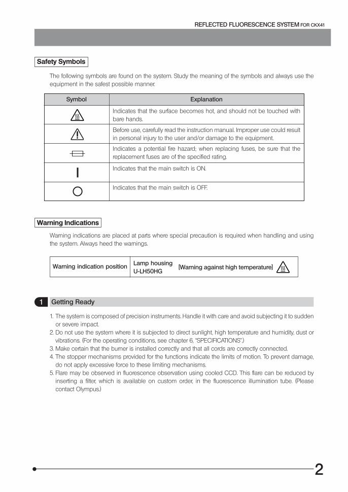
Warning Indications
Warning indications are placed at parts where special precaution is required when handling and usingthe system. Always heed the warnings.
Warning indication position
1 Getting Ready
Lamp housingU-LH50HG
[Warning against high temperature]
1. The system is composed of precision instruments. Handle it with care and avoid subjecting it to suddenor severe impact.
2. Do not use the system where it is subjected to direct sunlight, high temperature and humidity, dust orvibrations. (For the operating conditions, see chapter 6, “SPECIFICATIONS”.)
3. Make certain that the burner is installed correctly and that all cords are correctly connected.4. The stopper mechanisms provided for the functions indicate the limits of motion. To prevent damage,
do not apply excessive force to these limiting mechanisms.5. Flare may be observed in fluorescence observation using cooled CCD. This flare can be reduced by
inserting a filter, which is available on custom order, in the fluorescence illumination tube. (Pleasecontact Olympus.)
3
2 Maintenance and Storage
1. Be careful to avoid leaving dirt or fingerprints on the lenses, filters and high-pressure mercury burner,for contamination of these parts may cast the shadow of a foreign object in the field of view orcompromises the burner performance.If a glass component is contaminated, clean it by wiping gently with gauze. To remove fingerprints or oilsmudges, wipe with gauze slightly moistened with a mixture of ether (70%) and alcohol (30%).Since solvents such as ether and alcohol are highly flammable, they must be handled carefully.Be sure to keep these chemicals away from open flames or potential sources of electricalsparks —— for example, electrical equipment that is being switched on or off. Also rememberto always use these chemicals only in a well-ventilated room.
2. The mercury burner has an average service life of 100 hours. When the hour counter on the powersupply unit indicates 100 hours, replace the burner with a new one (see page 26).Using a burner after its service life expires could lead to the burner exploding, though this occurs veryrarely.
3. The surfaces of the dichroic mirror and excitation/barrier filters are very delicate. When it becomesnecessary to clean it, please contact Olympus.
4. Do not disassemble any part of the system as this could result in malfunction or reduced performance.
If the system is used in a manner not specified by this manual, the safety of the user may be imperiled.In addition, the equipment may also be damaged. Always use the equipment as outlined in this instruc-tion manual.
3 Caution
The following symbols are used to set off text in this instruction manual.: Indicates that failure to follow the instructions in the warning could result in bodilyharm to the user and/or damage to equipment (including objects in the vicinity of theequipment).
# : Indicates that failure to follow the instructions could result in damage to equipment.} : Indicates commentary (for ease of operation and maintenance).
4
REFLECTED FLUORESCENCE SYSTEM FOR CKX41
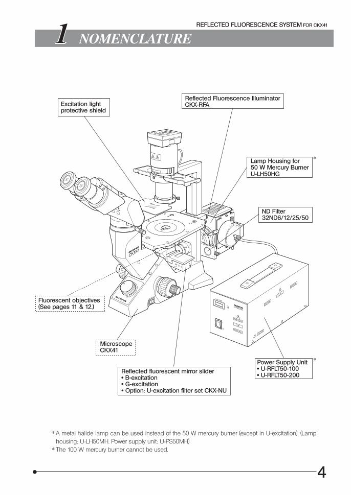
NOMENCLATURE
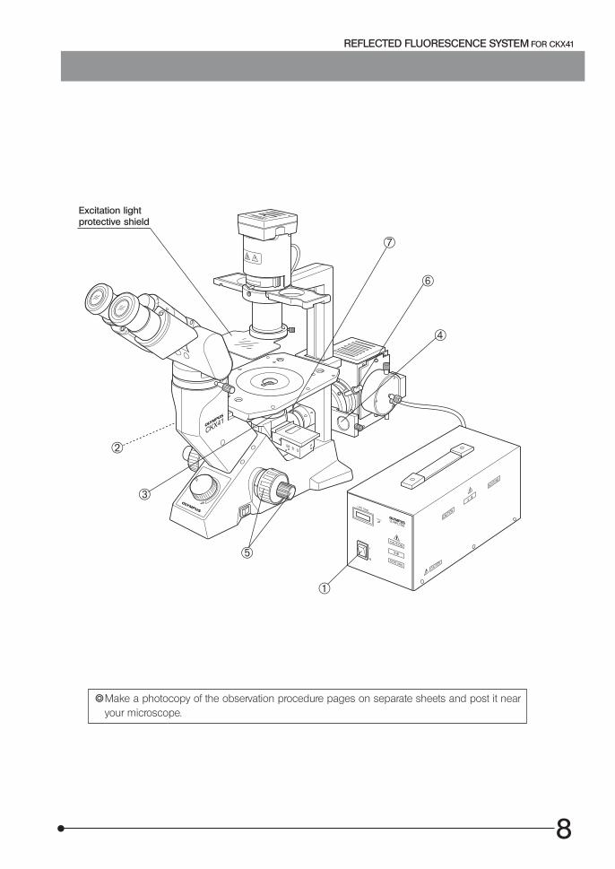
Excitation lightprotective shield
Reflected Fluorescence Illuminator CKX-RFA
Lamp Housing for50 W Mercury Burner
U-LH50HG
*
ND Filter32ND6/12/25/50
Fluorescent objectives (See pages 11 & 12.)
Microscope CKX41
Reflected fluorescent mirror slider · B-excitation · G-excitation · Option: U-excitation filter set CKX-NU
Power Supply Unit · U-RFLT50-100 · U-RFLT50-200
* A metal halide lamp can be used instead of the 50 W mercury burner (except in U-excitation). (Lamphousing: U-LH50MH. Power supply unit: U-PS50MH)
* The 100 W mercury burner cannot be used.
*

5
CONTROLS OF EACH MODULE
Reflected Fluorescence Illuminator CKX-RFA
Fluorescent mirror switching lever
This can also be attachedon the opposite side.
BF light path
B-excitation
G-excitation
Light path indicators*
Fluorescent mirror slider
BF/B-excitation/G-excitation.
Field iris diaphragm lever
To open : Turn clockwise.To stop down : Turn counterclockwise.
Field iris diaphragm centering screws
Turn using the provided Allen wrench.
Filter slider
Shutter/Open position/Filter pocket
Dust covers (x 2)With two clamping knobs.
* View of light path indicators from the front side of microscope
ND Filter 32ND6/12/25/50Light Path G-excitation B-excitation Brightfield
View No indication
Lamp Housing U-LH50HG
Collectorfocusing knob
Burner left/rightcentering knob
Burner up/downcentering knob
Rear view
Mirror left/rightcentering screw
Mirror focusingscrew
Mirror up/downcentering screw
6
REFLECTED FLUORESCENCE SYSTEM FOR CKX41
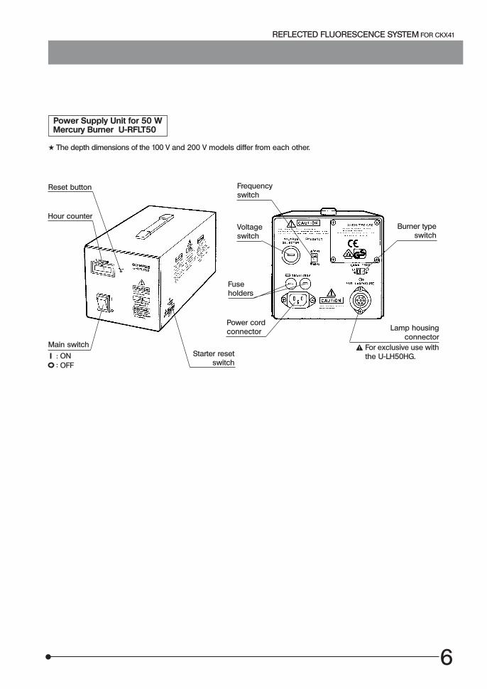
Power Supply Unit for 50 W Mercury Burner U-RFLT50
# The depth dimensions of the 100 V and 200 V models differ from each other.
Reset button
Hour counter
Main switch
: ON: OFF
Starter resetswitch
Frequencyswitch
Voltageswitch
Burner typeswitch
Fuseholders
Power cordconnector Lamp housing
connectorFor exclusive use withthe U-LH50HG.
7
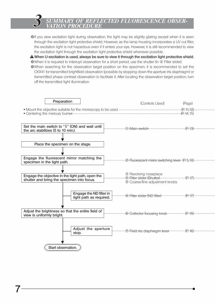
SUMMARY OF REFLECTED FLUORESCENCE OBSER-VATION PROCEDURE
}If you view excitation light during observation, the light may be slightly glaring except when it is seenthrough the excitation light protective shield. However, as the lamp housing incorporates a UV cut filter,the excitation light is not hazardous even if it enters your eye. However, it is still recommended to viewthe excitation light through the excitation light protective shield whenever possible.When U-excitation is used, always be sure to view it through the excitation light protective shield.
}When it is required to interrupt observation for a short period, use the shutter (in 4 Filter slider).}When searching for the observation target position on the specimen, it is recommended to set the
CKX41 for transmitted brightfield observation (possible by stopping down the aperture iris diaphragm) ortransmitted phase contrast observation to facilitate it. After locating the observation target position, turnoff the transmitted light illumination.
(Controls Used) (Page)Preparation
· Mount the objective suitable for the microscopy to be used.· Centering the mercury burner.
(P. 11,12)(P. 14,15)
Set the main switch to “ ” (ON) and wait untilthe arc stabilizes (5 to 10 min.). 1 Main switch (P. 13)
Place the specimen on the stage.
Engage the fluorescent mirror matching thespecimen in the light path. 2 Fluorescent mirror switching lever (P. 5,10)
Engage the objective in the light path, open theshutter and bring the specimen into focus.
3 Revolving nosepiece4 Filter slider (Shutter)5 Coarse/fine adjustment knobs
(P. 17)
Engage the ND filter inlight path as required. 4 Filter slider (ND filter) (P. 17)
Adjust the brightness so that the entire field ofview is uniformly bright. 6 Collector focusing knob (P. 15)
Adjust the aperturestop. 7 Field iris diaphragm lever (P. 16)
Start observation.
8
REFLECTED FLUORESCENCE SYSTEM FOR CKX41
Excitation lightprotective shield
}Make a photocopy of the observation procedure pages on separate sheets and post it nearyour microscope.
1
2
3
4
6
7
5

9
USING THE CONTROLS
1 General Precautions for Observation
1. Confirm that the power supply unit has been set to the proper power supply voltage, powersupply frequency and burner type. Improper setting of these items may degrade burner servicelife considerably.
2. Confirm that the power cord and connecting cords are connected properly.3. When transmitted phase contrast or transmitted relief contrast observation is required, leave an open
position (BF) in the reflected fluorescent mirror slider. This position will allow the original colors to bereproduced.
4. Stop down the field iris diaphragm until its image circumscribes the field of view. If it is decentered,adjust centering using the Allen screwdriver. (P.16)
5. When using an LCPlanFl series objective, attach the correction cap, which compensates for the materialand thickness of the container used in observation. For the type of the correction cap to be used, referto the instruction manual for the CKX series culture microscopes.
6. The LUCPlanFLN20X/40X/60X, LCPlanFl40X and LUCPlanFl40X objectives with correction collar arecapable of compensating for the drop in resolution due to variance in the cover glass thickness. Fordetails, refer to the instruction manual for the CKX series culture microscopes.
7. When it is required to interrupt observation for a short period, use the shutter. (Repeated on-off of themercury burner will shorten its service life considerably.)
8. Precautions on the specimen color fading:The system employs high-intensity excitation light to enable bright observation of dark fluorescentspecimens.As a result, if high-power objectives are used frequently, color fading of the specimen occurs early,degrading the view (contrast) of fluorescent images.To delay color fading of the specimen and obtain favorable fluorescent images, it is recommended toreduce the excitation light intensity a little.The excitation light intensity can be reduced by using ND filters to an extent that does not hinderobservation. It is also effective to use the shutter frequently to avoid illuminating the specimen for alonger period than required.Color fading of the specimen can also be delayed using a commercially available color fading preventingagent (DABCO, etc.).The use of color fading preventing agent is recommended specially when you perform high-magnificationobservation frequently.
#Note that color fading preventing agent cannot be used with certain specimens.
10
REFLECTED FLUORESCENCE SYSTEM FOR CKX41
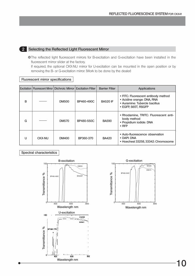
2 Selecting the Reflected Light Fluorescent Mirror
}The reflected light fluorescent mirrors for B-excitation and G-excitation have been installed in thefluorescent mirror slider at the factory.If required, the optional CKX-NU mirror for U-excitation can be mounted in the open position or byremoving the B- or G-excitation mirror. (Work to be done by the dealer)
Fluorescent mirror specifications
Excitation Fluorescent Mirror Dichroic Mirror Excitation Filter Barrier Filter Applications
B DM500 BP460-490C BA520 IF
· FITC: Fluorescent antibody method· Acidine orange: DNA, RNA· Auramine: Tubercle bacillus· EGFP, S65T, RSGFP
G DM570 BP480-550C BA590
· Rhodamine, TRITC: Fluorescent anti-body method
· Propidium iodide: DNA· RFP
U CKX-NU DM400 BP360-370 BA420· Auto-fluorescence observation· DAPI: DNA· Hoechest 33258, 33342: Chromosome
Spectral characteristics
B-excitation
Tran
smitt
ance
%
Wavelength nm
G-excitation
Tran
smitt
ance
%
Wavelength nm
U-excitation
Wavelength nm
Tran
smitt
ance
%

11
3 Applicable Fluorescence Objectives
Excitation B, G U, B, G
Applicableobjectives
PlanCN 4XPlanCN 10X
UPlanFLN 4XUPlanFLN 10XUPlanFLN 20XLUCPlanFLN 40XLCAchN 20XPh/PhP
LUCPlanFLN 20X PlanCN 20X
LUCPlanFLN 40X
Microscopy
Microscopy Fluorescence
Fluorescence/Phase Contrast
IX2-SL IX2-SLP
Excitation B, G
Specimen Plastic petri dishPlastic petri dish
Multi-well / Dish, etc. Dish, etc.
Applicableobjectives
UPlanFLN 4XPh UPlanFLN 4XPhPCAchN 10XPhPLCAchN 20XPhPLCAchN 40XPhP
CPlanN 10XPh PlanN 10XPh
LCAchN 20XPh LUCPlanFLN 20XPh
LCAchN 40XPh
(Note) When a phase contrast objective is used in fluorescence observation, the brightness or contrast maysometimes be deteriorated slightly.
UIS2 Series
Specimen Plastic petri dish Slide glass Slide glass
12
REFLECTED FLUORESCENCE SYSTEM FOR CKX41
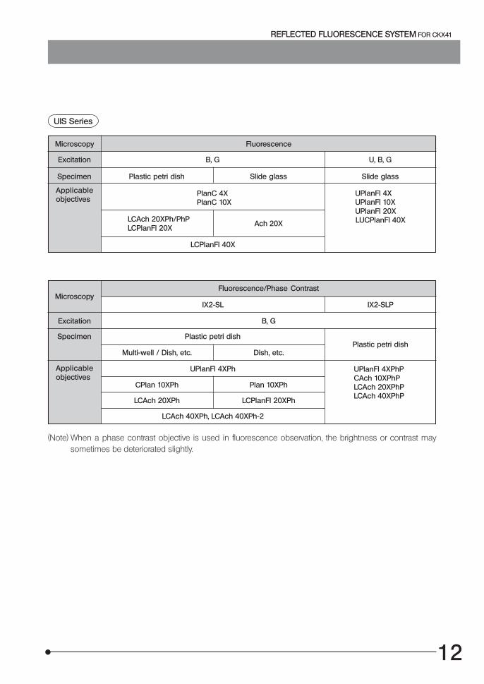
Excitation B, G U, B, G
Applicableobjectives
PlanC 4XPlanC 10X
UPlanFl 4XUPlanFl 10XUPlanFl 20XLUCPlanFl 40XLCAch 20XPh/PhP
LCPlanFl 20XAch 20X
LCPlanFl 40X
Microscopy
Microscopy Fluorescence
Fluorescence/Phase Contrast
IX2-SL IX2-SLP
Excitation B, G
Specimen Plastic petri dishPlastic petri dish
Multi-well / Dish, etc. Dish, etc.
Applicableobjectives
UPlanFl 4XPh UPlanFl 4XPhPCAch 10XPhPLCAch 20XPhPLCAch 40XPhP
CPlan 10XPh Plan 10XPh
LCAch 20XPh LCPlanFl 20XPh
LCAch 40XPh, LCAch 40XPh-2
(Note) When a phase contrast objective is used in fluorescence observation, the brightness or contrast maysometimes be deteriorated slightly.
UIS Series
Specimen Plastic petri dish Slide glass Slide glass

13
· Set the main switch of the power supply unit to “ ” (ON). Thearc will stabilize in 5 to 10 minutes after ignition.
#Some mercury burners may not ignite the first time thepower is turned ON due to variance in production, andthe safety mechanism in the starter of the power supplyunit is activated to reset the starter in such a case. If thisoccurs, set the main switch to “ ” (OFF) once, theninsert a thin object such as a mechanical pencil tip intothe starter reset hole 1 on the right panel of the powersupply unit to press the internal switch, and set the mainswitch to “ ” (ON) again.
#To avoid shortening the power supply unit’s operatinglife, avoid turning power on while the burner is notmounted or turning power on and off within short timeintervals.
#To avoid shortening the burner life, do not turn theburner off within 15 minutes after ignition. Use theshutter instead.
#After the burner is turned off, it cannot be re-ignitedbefore the mercury vapor cools and condenses toliquid. Wait about 10 minutes before restarting theburner.If the lamp housing is opened while the burner is ignited,the safety interlock will activate and switch off the powerautomatically. In this case, set the main switch to “ ”(OFF) and wait for more than 10 minutes before restartingthe burner. The lamp housing can be opened only afterit has cooled down fully.When resetting the hour counter, be sure to press thereset button until “0.0” is displayed.When the hour counter indicates “100.0”, set the mainswitch to “ ” (OFF) for safety, wait for more than 10minutes, then replace the lamp burner after making surethat the lamp housing has cooled down.A mercury burner seals high-pressure gas inside. Ifthe burner is used beyond its service life, stress mayaccumulate inside the burner, and in the worst (butvery rare) case, the burner could explode.
1
Fig. 1
4 Turning On the Mercury Burner (Fig. 1)
14
REFLECTED FLUORESCENCE SYSTEM FOR CKX41
1
2
3
Fig. 2
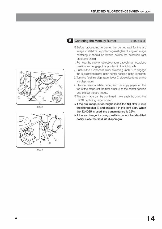
5 Centering the Mercury Burner (Figs. 2 to 6)
}Before proceeding to center the burner, wait for the arcimage to stabilize. To protect against glare during arc imagecentering, it should be viewed across the excitation lightprotective shield.
1. Remove the cap (or objective) from a revolving nosepieceposition and engage this position in the light path.
2. Push in the fluorescent mirror switching knob 1 to engagethe B-excitation mirror in the center position in the light path.
3. Turn the field iris diaphragm lever 2 clockwise to open theiris diaphragm.
4. Place a piece of white paper, such as copy paper, on thetop of the stage, set the filter slider 3 to the center positionand project the arc image.
}The arc image can be confirmed more easily by using theU-CST centering target screen.
#If the arc image is too bright, insert the ND filter 4 intothe filter pocket 5 and engage it in the light path. Whenthe 32ND25 is used, the transmittance is 25%.
# If the arc image focusing position cannot be identifiedeasily, close the field iris diaphragm.
Fig. 3
45

15
5 . Project the arc image on the white paper, then center andsharpen it by manipulating the collector focusing knob 6,burner left/right centering knob 7 and burner up/downcentering knob 8 on the lamp housing. (Figs. 4 & 5)
# There may be causes in which the arc image projectedon the white paper is a mirror-reflected image. If thearc image moves when the mirror left/right centeringscrew 9 or mirror up/down centering screw a is turned,it is a mirror-reflected image; bring it out of the field andcenter the arc image as described above. (Fig. 4)
6 . Manipulate the burner left/right centering knob 7 slightlyto move the arc image to the right (or left). (Figs. 4 & 6 A)
7 . Using the Allen wrench provided with the illuminator, turnthe mirror focusing screw 9, mirror left/right centeringscrew 9 and mirror up/down centering screw a to formthe mirror-reflected arc image on the white paper. (Figs. 4& 6 B)
8 . Adjust the mirror centering screws 9 and a to move thedirect and mirror-reflected arc images in the symmetricalposition between each other, and turn the mirror focusingscrew b to adjust the size of the mirror-reflected imageuntil it is identical to that of the direct image. (Figs. 4 & 6 C)
9 . Turn the burner left/right centering screw 7 to overlap thedirect image with the mirror-reflected image. (Figs. 4 & 6 D)
10. Engage the 10X objective in the light path while continuingto use the B-excitation mirror.
11. Place a specimen on the stage and bring into approximatefocus.
12. Look into the eyepiece and manipulate the collectorfocusing knob 6 to make the field as bright as regularas possible, then turn the knob clockwise to tighten.
(Fig. 4)} Maintain this condition until the next time the burner is
replaced.
Fig. 4
Fig. 5
Fig. 6
…† ‡
‹Š
‰
Fig. 6
Mirror reflectedimage
¬
®
¯
¶
Terminal
Arc image
Terminal

16
REFLECTED FLUORESCENCE SYSTEM FOR CKX41
Fig. 7
Fig. 8
12
6 Centering the Field Iris Diaphragm (Figs. 7 & 8)
1. Engage the 10X objective in the light path, push in the fluo-rescent mirror switching knob to engage the B-excitationmirror in the light path, and set the filter slider to the centralopen position or the position of the ND filter.
2. Place a specimen on the stage and bring into approximatefocus.
3. Turn the field iris diaphragm lever 1 counterclockwise littleby little, and confirm the iris diaphragm position.
4. Using the provided Allen wrench, turn the two field iriscentering screws 2 alternately to move the image of thediaphragm to the center.
5. After moving the diaphragm image to the center, open thefield iris diaphragm. As this makes slight deviation notice-able, adjust the centering precisely.
6. After completion of centering, engage the iris diaphragmdiameter until it just circumscribes the field of view.
Adjusting the field iris diaphragm
The field iris diaphragm adjusts the diameter of the illumi-nating beam to obtain good image contrast.Keeping the field iris diaphragm stopped down to the small-est required area for each observation makes it possible toprevent color fading of areas outside the observation targetregion.According to the objective in use, adjust the diaphragmimage using the field iris diaphragm lever so that thefield of view is circumscribed by the field iris diaphragmto exclude stray light.

17
123
Fig. 9
}Hold the knob of the filter slider 1 on the illuminator andmove the knob to the left and right to select one of the threepositions, which are arranged in order of the filter pocket,open position and shutter from the right to the left.To adjust the observation brightness, insert an optimum NDfilter (32ND6, 32ND12, 32ND25 or 32ND50) into the filterpocket and set the filter slider to engage it in the light path.When not performing observation, set the filter to the shutterposition to prevent the specimen fluorescence color fadingby cutting the excitation light.
ND filter
}The ND filter can reduce the excitation light intensity todelay color fading of the specimen. Use the ND filter as faras this does not hinder operation.
1. Slide the filter slider 1 on the illuminator in the direction ofthe arrow.
2. Drop in the ND filter 3 into the filter pocket 2.#To prevent the ND filter from being cracked, insert it so
that the surface with indications faces the observationside.When replacing the ND filter, be sure to wait until the NDfilter cools down.When the mercury burner is lit for a long period while anND filter is inserted, the filter and its metallic frame willbecome very hot. Take care not to burn yourself.Do not leave the filter slider to a position other than theclick positions for a long period.
}A filter other than ND filter can also be inserted provided thatthe outer diameter is 32 mm and the thickness is 3 mm orless.
#Use a reflection type ND filter (32ND6, 12, 25 or 50). Donot use a commercially available low-reflection ND filteras this may crack or burn the filter.
7 Switching the Filter Slider (Fig. 9)
18
REFLECTED FLUORESCENCE SYSTEM FOR CKX41
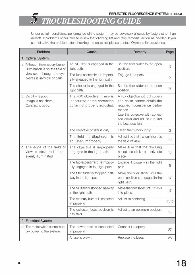
TROUBLESHOOTING GUIDEUnder certain conditions, performance of the system may be adversely affected by factors other thandefects. If problems occur, please review the following list and take remedial action as needed. If youcannot solve the problem after checking the entire list, please contact Olympus for assistance.
17
5
17
–
Problem Cause Remedy Page
1. Optical System
a ) Although the mercury burnerillumination is on, the field ofview seen through the eye-pieces is invisible or dark.
An ND filter is engaged in thelight path.
Set the filter slider to the openposition.
The fluorescent mirror is improp-erly engaged in the light path.
Engage it properly.
The shutter is engaged in thelight path.
Set the filter slider to the openposition.
b) Visibility is poor.Image is not sharp.Contrast is poor.
The 40X objective in use isinaccurate or the correctioncollar not properly adjusted.
A 40X objective without correc-tion collar cannot obtain therequired fluorescence perfor-mance.Use the objective with correc-tion collar and adjust it to findthe best position.
The objective or filter is dirty. Clean them thoroughly.
The field iris diaphragm isadjusted improperly.
Adjust it so that it circumscribesthe field of view.
c ) The edge of the field ofview is obscured or notevenly illuminated
The objective is improperlyengaged in the light path.
Make sure that the revolvingnosepiece clicks properly intoplace.
The fluorescent mirror is improp-erly engaged in the light path.
Engage it properly in the lightpath.
The filter slider is stopped half-way in the light path.
Move the filter slider until theopen position is engaged in thelight path.
The ND filter is stopped halfwayin the light path.
Move the filter slider until it clicksinto place.
The mercury burner is centeredimproperly.
Adjust its centering.
The collector focus position isdeviated.
Adjust to an optimum position.
2. Electrical System
a ) The main switch cannot sup-ply power to the system.
The power cord is connectedimproperly.
Connect it properly.
A fuse is blown. Replace the fuses.
3
16
16
5
17
17
14,15
15
27
28

19
b) The main switch can be setto ON but the burner doesnot ignite.
Problem Cause Remedy Page
The lamp housing connectingcord is connected improperly.
Connect it properly to the con-nectors.
The mercury burner is notmounted.
Attach a mercury burner.
The safety mechanism in thelamp housing is activated.
Tighten the lamp burner socketclamping screw firmly.
The auto ignition system is mal-functioning.
Set the main switch of the powersupply unit to “ ” (OFF) then “ ”(ON) again.(Repeated ON-OFF is possiblein this case.)
c ) The mercury burner flickersor the brightness is low.
The auto ignition safety mecha-nism is activated.
Press the switch inside thestarter reset hole on the rightpanel of the power supply unit,and then set the main switch to“ ” (ON) again.
This phenomenon is observedin a short period after ignition.
Wait for 10 minutes or moreafter ignition.
The power supply voltageand/or frequency switches areset improperly.
Set them properly.
The burner life has expired. Replace the mercury burner.
d) The service lives of mercuryburners are very short.
The power supply voltage is setimproperly.
Set it properly.
27
25, 26
25
13
13
13
27
25, 26
27

20
REFLECTED FLUORESCENCE SYSTEM FOR CKX41
SPECIFICATIONS
Module Specifications
Reflected Fluorescence Illumi-natorCKX-RFA
Fluorescent lighting method: Reflected fluorescent lighting based on slideswitching of fluorescent mirrors.
Fiend number: 22 (when the WH10X is used).Shutter: Switching using filter slider (Shutter/Open position/Filter pocket ).Excitation light protective shield: Fixed on condenser with a screw.Possible observation methods:B-excitation, G-excitation, U-excitation
(optional).
Lamp Housing for 50W MercuryBurnerU-LH50HG
Burner centering, Up/down, left/right.Mirror centering: Up/down, left/right.Burner focusing: Collector focusing and mirror focusing screw system.Safety mechanism: Interlock switch, UV cut filter built in.<< Applicable high-pressure mercury burners >> · HBO50W/AC (OSRAM) · CS50W4 (PHILIPS)
Power Supply UnitU-RFLT50-100U-RFLT50-200
Ignition system: Auto ignition.Hour counter: Displays the accumulated hours of operation.Input rating: Input voltage switchable. U-RFLT50-100: 100/110/120 V AC , 2.5/2.3/2.0 A, 50/60 Hz U-RFLT50-200: 220/230/240 V AC , 1.7 A, 50/60 HzDimensions U-RFLT50-100: 150(W) x 150(H) x 320(D) mm U-RFLT50-200: 150(W) x 150(H) x 210(D) mmWeight U-RFLT50-100: 12 kg (26.4 lbs) U-RFLT50-200: 7 kg (15.4 lbs.)
Operating environment Indoor use.Altitude: Max. 2000 meters.Ambient temperature: 5° to 40°C (41° to 104°F).Maximum relative humidity: 80% for temperatures up to 31°C (88°F ),
decreasing linearly through 70% at 34°C(93°F ), 60% at 37°C (99°F), to 50% relativehumidity at 40°C (104°F).
Supply voltage fluctuations; Not to exceed ±10% of the normal voltage.Pollution degree: 2 (in accordance with IEC60664).Installation category (Overvoltage category): II (in accordance with IEC60664).

21
ASSEMBLY
7-1 Assembly Diagram
The diagram below shows how to assemble the various modules for the microscope system. Thenumbers in the diagram indicates the assembly step order.
#When assembling the microscope system, make sure that all parts are free of dust and dirt, andavoid scratching any parts or touching the glass surfaces.
Dust cover
Fluorescentmirror slider
MicroscopeCKX41
Excitation light protective shield
Reflected FluorescenceIlluminatorCKX-RFA
Dust cover
Dummy cover
Lamp HousingU-LH50HG
Mercury burner
Power cord
Power Supply UnitU-RFLT50-100U-RFLT50-200
22
REFLECTED FLUORESCENCE SYSTEM FOR CKX41
7-2 Detailed Assembly Procedure
1
2
3
Fig. 10
1
2
2
Fig. 11
3
4
Fig. 12
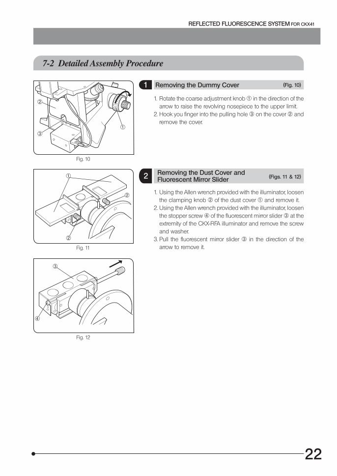
1. Rotate the coarse adjustment knob 1 in the direction of thearrow to raise the revolving nosepiece to the upper limit.
2. Hook you finger into the pulling hole 3 on the cover 2 andremove the cover.
1 Removing the Dummy Cover (Fig. 10)
2 (Figs. 11 & 12)Removing the Dust Cover andFluorescent Mirror Slider
1. Using the Allen wrench provided with the illuminator, loosenthe clamping knob 2 of the dust cover 1 and remove it.
2. Using the Allen wrench provided with the illuminator, loosenthe stopper screw 4 of the fluorescent mirror slider 3 at theextremity of the CKX-RFA illuminator and remove the screwand washer.
3. Pull the fluorescent mirror slider 3 in the direction of thearrow to remove it.
23
1
2
3
Fig. 13
1
2
3
4
Fig. 14
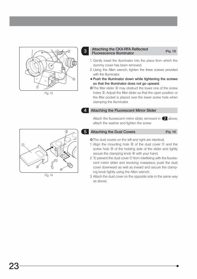
3 (Fig. 13)Attaching the CKX-RFA ReflectedFluorescence Illuminator
1. Gently insert the illuminator into the place from which thedummy cover has been removed.
2. Using the Allen wrench, tighten the three screws providedwith the illuminator.
#Push the illuminator down while tightening the screwsso that the illuminator does not go upward.
}The filter slider 3 may obstruct the lower one of the screwholes 2. Adjust the filter slider so that the open position orthe filter pocket is placed over the lower screw hole whenclamping the illuminator.
4 Attaching the Fluorescent Mirror Slider
Attach the fluorescent mirror slider, removed in 2 above,attach the washer and tighten the screw.
5 Attaching the Dust Covers (Fig. 14)
}The dust covers on the left and right are identical.1. Align the mounting hole 2 of the dust cover 1 and the
screw hole 3 of the holding side of the slider and lightlysecure the clamping knob 4 with your hand.
2. To prevent the dust cover 1 from interfering with the fluores-cent mirror slider and revolving nosepiece, push the dustcover downward as well as inward and secure the clamp-ing knob tightly using the Allen wrench.
3. Attach the dust cover on the opposite side in the same wayas above.
24
REFLECTED FLUORESCENCE SYSTEM FOR CKX41
1
2
3
Fig. 15
1
2 3
4
5
Fig. 16
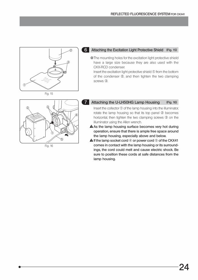
6 Attaching the Excitation Light Protective Shield (Fig. 15)
}The mounting holes for the excitation light protective shieldhave a large size because they are also used with theCKX-RCD condenser.Insert the excitation light protective shield 1 from the bottomof the condenser 2, and then tighten the two clampingscrews 3.
7 Attaching the U-LH50HG Lamp Housing (Fig. 16)
Insert the collector 1 of the lamp housing into the illuminator,rotate the lamp housing so that its top panel 2 becomeshorizontal, then tighten the two clamping screws 3 on theilluminator using the Allen wrench.As the lamp housing surface becomes very hot duringoperation, ensure that there is ample free space aroundthe lamp housing, especially above and below.If the lamp socket cord 4 or power cord 5 of the CKX41comes in contact with the lamp housing or its surround-ings, the cord could melt and cause electric shock. Besure to position these cords at safe distances from thelamp housing.
25
1
Fig. 17
2
3
4
Fig. 18
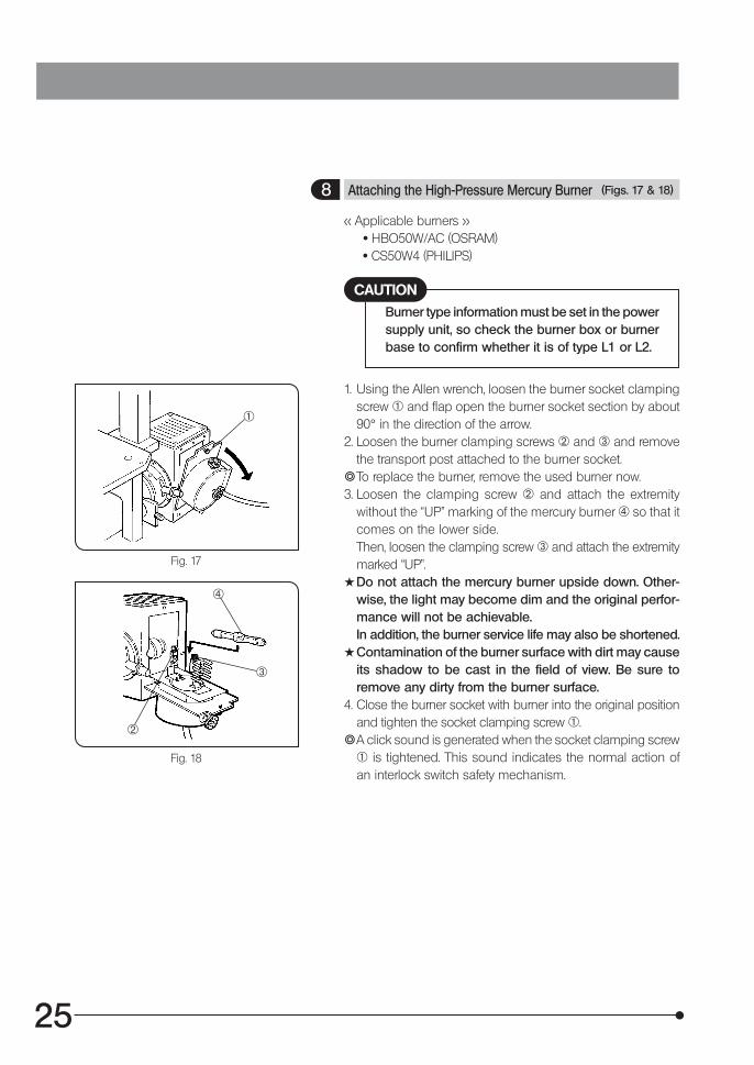
8 Attaching the High-Pressure Mercury Burner (Figs. 17 & 18)
<< Applicable burners >> · HBO50W/AC (OSRAM) · CS50W4 (PHILIPS)
Burner type information must be set in the powersupply unit, so check the burner box or burnerbase to confirm whether it is of type L1 or L2.
CAUTION
1. Using the Allen wrench, loosen the burner socket clampingscrew 1 and flap open the burner socket section by about90° in the direction of the arrow.
2. Loosen the burner clamping screws 2 and 3 and removethe transport post attached to the burner socket.
}To replace the burner, remove the used burner now.3. Loosen the clamping screw 2 and attach the extremity
without the “UP” marking of the mercury burner 4 so that itcomes on the lower side.Then, loosen the clamping screw 3 and attach the extremitymarked “UP”.
#Do not attach the mercury burner upside down. Other-wise, the light may become dim and the original perfor-mance will not be achievable.In addition, the burner service life may also be shortened.
#Contamination of the burner surface with dirt may causeits shadow to be cast in the field of view. Be sure toremove any dirty from the burner surface.
4. Close the burner socket with burner into the original positionand tighten the socket clamping screw 1.
}A click sound is generated when the socket clamping screw1 is tightened. This sound indicates the normal action ofan interlock switch safety mechanism.

26
REFLECTED FLUORESCENCE SYSTEM FOR CKX41
5. Set the burner type switch 5 on the rear of the powersupply unit according to the type of the mounted burner(L1 or L2). (Fig. 19)
#If the burner socket clamping screw 1 is loosened whilethe burner is on, the interlock switch turns off the burner.
(Fig. 17)To restart the burner, first set the main switch of the powersupply unit to “ ” (OFF), wait for about 10 minutes*.Then, after firmly tightening the clamping screw, set themain switch to “ ” (ON) again.
* The burner cannot be re-ignited for about 10 minutes,that is, until the mercury vapor inside it has cooled downand condenser to liquid.
Caution for burner replacement during observation
The burner, lamp housing and its surroundings are veryhot during operation.Before replacing the burner, set the main switch to “ ”(OFF), unplug the power cord and wait until the burner,lamp housing and its surroundings cool down completely.
6. Press the reset button 6 on the front of the power supplyunit to reset the hour counter display to “0.0”. (Fig. 20)
}The unit of hour counter display is hour. Replace the burnerwhen the displayed time reaches “100.0” hours.Note that the above-mentioned life of a mercury burner mayexpire before the above-mentioned average depending onhow frequently the main switch is set to “ ” (ON) and “ ”(OFF). When ignition of the burner deteriorates or flickeringbecomes noticeable, replace the burner regardless of thehour counter display.
#Be sure to reset to “0.0”. Otherwise, the burner may notbe ignitable.Clear mode than 10 cm of space around the powersupply unit to assure proper heat radiation.The power supply unit should be installed so that themain switch can easily be accessed and set to “ ” (OFF)in case of emergency.
5
Fig. 19
6
Fig. 20

27
Setting the input power voltage
1. Using a flat-blade screwdriver, set the voltage switch 1 onthe rear of the power supply unit to your local power voltage.
2. Set the frequency switch 2 to your local power frequency.#Improper setting of the above switches may degrade
burner performance, or in the worst case (although veryrare), cause the burner to explode.Cables and cords are vulnerable when bent or twisted.Never subject them to excessive force.Make sure that the main switch of the power supply isset to “ ” (OFF) before connecting cables.
1. Plug the connector 3 from the burner socket securely intothe connector 4 on the power supply unit. (Fig. 22)Always use the U-LH50HG Lamp Housing.Always use the power cord provided by Olympus. If nopower cord is provided, please select the proper powercord by referring to the section “PROPER SELECTIONOF THE POWER SUPPLY CORD” at the end of thisinstruction manual. If the proper power cord is not used,product safety performance cannot be warranted.
2. Connect the power cord connector 5 to connector 6 firmly. (Fig. 22)
3. Connect the power cord plug 7 to a wall outlet 8. (Fig. 23)Be sure to supply power from a grounded, 3-conductorpower outlet using the proper power cord. If the poweroutlet is not grounded properly, Olympus can no longerwarrant the electrical safety performance of the equip-ment.If the power cord or a connection cable comes in contactwith the lamp socket or surrounding equipment, the cordor cable may melt and result in shock hazard. To preventthis, distribute the cords and cables apart from the lamphousing.
1
2
Fig. 21
3
4
5
6
Fig. 22
7 8
Fig. 23
9 Connecting the Cords (Figs. 21 to 23)

28
REFLECTED FLUORESCENCE SYSTEM FOR CKX41
Fuse replacement (Fig. 24)
#Set the main switch to “ ” (OFF) and unplug the powercord before replacing fuses.
1. Remove each of the fuse holders 9 by turning it counter-clockwise using a flat-blade screwdriver and pulling out.
2. Replace both fuses with new ones.#Always use the designated fuses. Otherwise, a fire hazard
may result.
9
Fig. 24
Applicable fuses
U-RFTL50-100: T4A(H)250V(LITTELFUSE 215004), 2 pieces
U-RFTL50-200: T2.5A(H)250V(LITTELFUSE 215025), 2 pieces

29
U-EXCITATION FILTER SET CKX-NU (OPTIONAL)}The CKX-NU U-Excitation Filter Set should be mounted by the dealer in the position (fluorescent mirror
slider position) specified by the customer. (It is also possible, on custom order, to replace the U-excita-tion filters with excitation filter, barrier filter and/or dichroic mirror of the UIS fluorescent mirror unit series.)
Contents of the set
Excitation filter Barrier filter Filter holders (x 2)
Indication stickers (To be attached on the light path indicators)
Mirror holder
Construction of the fluorescent mirror slider
Filter holder
Barrier filter
Mirror holder
Dichroic mirror
BF light path shield plate
Excitation filter
All pieces can be placed and replaced usinga precision screwdriver.
Removing the UV cut filter (Fig. 25)
Loosen the holder ring 2 of the UV cut filter 1 in the front of the collector of the U-LH50HG lamphousing by turning the ring counterclockwise, and then take out the filter.
12
Fig. 25
Filter holders
30
REFLECTED FLUORESCENCE SYSTEM FOR CKX41
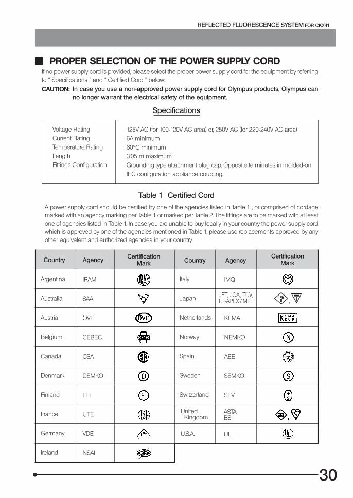
PROPER SELECTION OF THE POWER SUPPLY CORDIf no power supply cord is provided, please select the proper power supply cord for the equipment by referringto “ Specifications ” and “ Certified Cord ” below:
CAUTION: In case you use a non-approved power supply cord for Olympus products, Olympus canno longer warrant the electrical safety of the equipment.
Specifications
Voltage RatingCurrent RatingTemperature RatingLengthFittings Configuration
125V AC (for 100-120V AC area) or, 250V AC (for 220-240V AC area)6A minimum60°C minimum3.05 m maximumGrounding type attachment plug cap. Opposite terminates in molded-onIEC configuration appliance coupling.
Table 1 Certified Cord
A power supply cord should be certified by one of the agencies listed in Table 1 , or comprised of cordagemarked with an agency marking per Table 1 or marked per Table 2. The fittings are to be marked with at leastone of agencies listed in Table 1. In case you are unable to buy locally in your country the power supply cordwhich is approved by one of the agencies mentioned in Table 1, please use replacements approved by anyother equivalent and authorized agencies in your country.
Country Agency CertificationMark Country Agency
CertificationMark
Argentina
Australia
Austria
Belgium
Canada
Denmark
Finland
France
Germany
Ireland
IRAM
SAA
ÖVE
CEBEC
CSA
DEMKO
FEI
UTE
VDE
NSAI
Italy
Japan
Netherlands
Norway
Spain
Sweden
Switzerland
United Kingdom
U.S.A.
IMQ
KEMA
NEMKO
AEE
SEMKO
SEV
ASTABSI
UL
JET, JQA , TÜV,UL-APEX / MITI
31
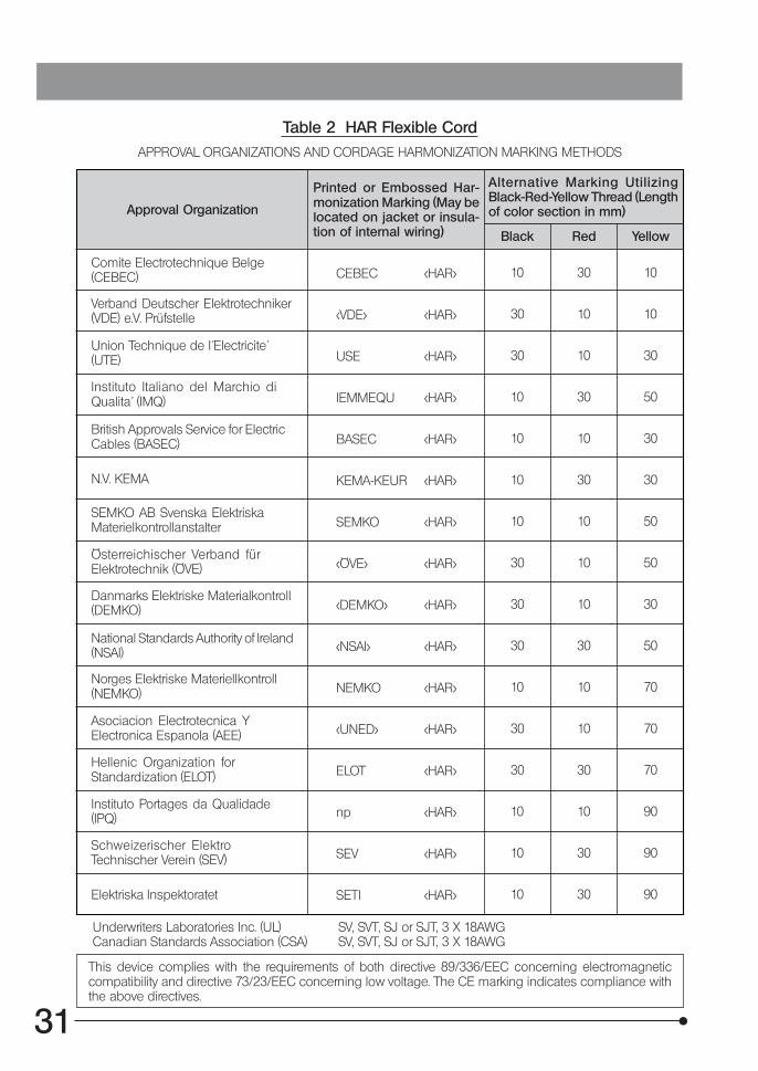
Table 2 HAR Flexible CordAPPROVAL ORGANIZATIONS AND CORDAGE HARMONIZATION MARKING METHODS
Approval Organization
Printed or Embossed Har-monization Marking (May belocated on jacket or insula-tion of internal wiring)
Alternative Marking UtilizingBlack-Red-Yellow Thread (Lengthof color section in mm)
Black Red Yellow
Comite Electrotechnique Belge(CEBEC)
Verband Deutscher Elektrotechniker(VDE) e.V. Prüfstelle
Union Technique de I´Electricite´(UTE)
Instituto Italiano del Marchio diQualita´ (IMQ)
British Approvals Service for ElectricCables (BASEC)
N.V. KEMA
SEMKO AB Svenska ElektriskaMaterielkontrollanstalter
Österreichischer Verband fürElektrotechnik (ÖVE)
Danmarks Elektriske Materialkontroll(DEMKO)
National Standards Authority of Ireland(NSAI)
Norges Elektriske Materiellkontroll(NEMKO)
Asociacion Electrotecnica YElectronica Espanola (AEE)
Hellenic Organization forStandardization (ELOT)
Instituto Portages da Qualidade(IPQ)
Schweizerischer ElektroTechnischer Verein (SEV)
Elektriska Inspektoratet
CEBEC <HAR>
<VDE> <HAR>
USE <HAR>
IEMMEQU <HAR>
BASEC <HAR>
KEMA-KEUR <HAR>
SEMKO <HAR>
<ÖVE> <HAR>
<DEMKO> <HAR>
<NSAI> <HAR>
NEMKO <HAR>
<UNED> <HAR>
ELOT <HAR>
np <HAR>
SEV <HAR>
SETI <HAR>
10 30 10
30 10 10
30 10 30
10 30 50
10 10 30
10 30 30
10 10 50
30 10 50
30 10 30
30 30 50
10 10 70
30 10 70
30 30 70
10 10 90
10 30 90
10 30 90
Underwriters Laboratories Inc. (UL) SV, SVT, SJ or SJT, 3 X 18AWGCanadian Standards Association (CSA) SV, SVT, SJ or SJT, 3 X 18AWG
This device complies with the requirements of both directive 89/336/EEC concerning electromagneticcompatibility and directive 73/23/EEC concerning low voltage. The CE marking indicates compliance withthe above directives.


2-43-2, Hatagaya, Shibuya-ku, Tokyo, Japan
Postfach 10 49 08, 20034, Hamburg, Germany
2 Corporate Center Drive, Melville, NY 11747-3157, U.S.A.
491B River Valley Road, #12-01/04 Valley Point Office Tower, Singapore 248373
2-8 Honduras Street, London EC1Y OTX, United Kingdom.
31 Gilby Road, Mt. Waverley, VIC 3149, Melbourne, Australia.
6100 Blue Lagoon Drive, Suite 390 Miami, FL 33126-2087, U.S.A.
This publication is printed on recycled paper.
Printed in Japan 2004 09 M 010–@


