
1
RESIDENTIAL CONSTRUCTION HANDBOOK 2012
REVISED 05/2017 RE: 2012 NC RESIDENTIAL CODE

2
PREFACE
This booklet was published to assist customers
with some of the most commonly asked questions
about the North Carolina Residential Code. The
current edition of the North Carolina Residential
Code became effective on March 1, 2012. This
handbook is to be used as only a guide and is not
intended to be a substitute for the current North
Carolina Residential Building Code. Great care
has been taken within this booklet to provide the
newest version of the code including any
amendments made to the current code. If a
conflict is found between these two publications,
the current North Carolina Residential Code will
prevail. Code references from the 2012 North
Carolina Residential Building Code (NCRC) and
the 2012 North Carolina Administrative Code and
Policies (NCACP) are listed for referral to the
code. Underlined text represents code language
added by North Carolina to the International
Residential which was used as the base code.
Should you need additional information regarding
a code interpretation you can refer to the North
Carolina Department of Insurance (NCDOI)
website. http://www.ncdoi.com/OSFM/Engineering_and_Codes/Default.a
spx?field1=Code_Interpretations&user=State_Building_Codes

3
TABLE OF CONTENTS
PHONE NUMBERS…………………………………………………... P. 4
PERMITS……………………………………………………………….. P. 6
INSPECTIONS………………………………………………………… P. 8
BUILDING PLANNING…………...………………………………… P. 13
PLUMBING FIXTURE CLEARENCE……………………………... P. 16
SMOKE AND CARBON MONOXIDE ALARMS……………….. P. 17-18
FOOTINGS……………………………………………….………..…... P. 19
FOUNDATIONS………………………………………………….…... P. 24-25
SLABS…………………………………………..…..…………………. P. 26-27
FOUNDATION BOLTS AND STRAPS……………………..….... P. 28-29
FRAMING…………………………………………..…………………. P. 30
NOTCHING AND BORING……………………………………….. P. 33-38
STUD SPACING………………..…………………………………….. P. 42
FASTNER SCHEDULE……………………………………………..,,, P. 43-51
GIRDER, HEADER SPANS…………………………………………. P. 52-59
FLOOR JOIST SPANS………………………………………………. P. 60-61
CANTILEVER………………………………………………………….. P. 62-63
CEILING SPANS…………..………………………………………..... P. 64-65
RAFTER SPANS………………..…………………………………….. P. 66-69
ROOF BRACING……………………………………………………… P. 70
STAIRWAYS...…………………………….………………………….. P. 71
HANDRAIL AND GUARDRAILS……………………………..….. P. 71,99
FIRESTOPPING…………………………………………………..…. P. 72-76
SAFETY GLAZING………………………………………………….. P. 77-82
INSULATION…………..…………………………………………..… P. 83
FINAL INSPECTION REQUIREMENTS……….………………… P. 84-87
EXTERIOR DECK CODE………………………………………….... P. 88-99
SWIMMING POOLS, SPAS, HOT TUBS……………………….. P. 100-103
REQUIREMENTS FOR SALES CENTER IN A RESIDENCE….. P. 104-105
PLAN REVIEW FOR CHILD CARE IN A RESIDENCE………… P. 106-109

4
Mecklenburg County Code Enforcement
2145 Suttle Avenue
Charlotte, NC 28208-5237
980-314-CODE (2633)
CUSTOMER SERVICE:…………………… 980-314-2633… EXT 0
PERMITTING:……………………………..980-314-2633… EXT 23
DOCUMENT / INSPECTIONS:………...980-314-2633… EXT 22
RTAC:…………………………………….980-314-2633… EXT 2123
CTAC:…………………………………….980-314-2633… EXT 2113
REVENUE COLLECTIONS:………………..980-314-2633... EXT 3
FAX:……………………………………........................866-851-3630
CONTROLLERS…RESIDENTIAL…...980-314-2633… EXT 2121
COMMERCIAL…980-314-2633.....EXT 2111
INSPECTIONS BY APPOINTMENT &
OVERTIME INSPECTIONS………………………….…704-200-4940
ZONING: …………………………….….…Charlotte: 704-336-7600
…………………………………….Cornelius: 704-896-2461
…………………………………….Davidson: 704-892-7591
……………………………..….Huntersville: 704-875-7000
…………………………….……...Mint Hill: 704-545-9726
………………………………...…Matthews: 704-507-3380
……………………………..……....Pineville: 704-507-3380
………………………….COUNTY NORTH: 980-721-0924
………………………....COUNTY SOUTH: 704-432-0709
MINIMUM HOUSING INSPECTOR COUNTY:
DAVIDSON CORNELIUS HUNTERSVILLE:…….... 980-722-7301
SOUTH: MATTHEWS MINT HILL:……………….. 704-634-8864
CLT NEIGHBORHOOD & DEVELOPMENT……… 704-336-7988
WELL / SEPTIC: …………………..….…………………980-314-1680
CITY PLANNING: …....………………………..…….…704-336-2205
REGISTER OF DEEDS: ……….….………………….... 704-336-2443
MECKLENBURG TAX OFFICE……………………..…704-336-7600
LEADPAINT RALEIGH: .........………...………….…..919-707-5950
For additional needs visit our website MeckPermit.com

5
RESIDENTIAL PLAN SUBMITTIAL PROCESS
Effective February 6, 2017, the Residential Plans
Submittal Process will implement new requirements for
project submittals.:
Residential construction projects that are less than 100
square feet do not require plan review.
Decks and screened porches do not require plan review.
The Residential Drawing Submittal Checklist has also
changed. Please refer to our website MeckPermit.com
for the most current requirements for plan submittal.
Basic requirements for plan submittal are:
Plans are drawn to scale.
Designer, engineer, or architect name, telephone and
address.
Property owner name/ address/ name of job.
Plan size: a minimum 8 1/2 x11 for projects 500 square
foot and under.
Plan size: a minimum 11 x 17 for projects over 500
square foot.
Plans should show all dimensions of footings,
foundations, framing details (floor, wall, roof) and
elevations. Provide all construction material types
including roof, wall coverings and energy requirements.
NOTES:________________________________________________________
_________________________________________________________________
_________________________________________________________________
_________________________________________________________________
_________________________________________________________________
_________________________________________________________________
_________________________________________________________________
_________________________________________________________________
_________________________________________________________________
_________________________________________________________________
_________________________________________________________________
_________________________________________________________________
_________________________________________________________________

6
PERMITS
When is a permit required?
NCACP Section 204.3.1 No person may commence or
proceed with the construction, reconstruction, alteration,
repair, movement to another site, removal or demolition of
any building without first securing from the Inspection
Department having jurisdiction, any and all permits required
by the State Building Code.
EXCEPTION: Permits shall not be required for any work
costing fifteen thousand dollars or less, UNLESS THE
WORK INVOLVES:
a. The addition, repair or replacement of load bearing
members or structures;
b. The installation, extension of any plumbing system; general
repair may not need a permit to be performed.
c. The installation, extension, alteration of any heating or
cooling system; general repair may not need a permit to be
performed.
d. The installation, extension, alteration of an electrical wire
system;
e. The use of materials not permitted by this code; or
f. The addition of roofing, excluding replacement of like
grade or fire resistance roofing.
Is labor cost included in the total cost of the
permit valuation?
NCACP Section 204.6 Yes, permit valuations shall include
total cost, such as electrical, gas, mechanical, plumbing
equipment, fire protection and other systems, including
materials and labor.
Does an accessory building need to be
permitted?
Section R101.2.1 Accessory buildings. 01/2015
Accessory buildings with any dimension greater than 12 feet
(3658mm) must meet the provisions of this code. Accessory
buildings may be constructed without a masonry or concrete

7
foundation, except in coastal high hazard or ocean hazard
areas, provided that all of the following conditions are met:
1. The accessory building shall not exceed 400 square feet
(37m2) or one story in height;
2. The building is supported on a wood foundation of
minimum 2x6 or 3x4 mudsill of approved wood in
accordance with Section R317; and
3. The building is anchored to resist overturning and sliding
by installing a minimum of one ground anchor at each
corner of the building. The total resisting force of the
anchors shall be equal to 20 psf (958 Pa) times the plan area
of the building.
Not all accessory buildings will require a permit. Any
building where all dimensions, including the mean roof
height, are 12 ft or less does not require building permits
and would only require a zoning permit.
Does an accessory structure need to be
permitted?
R101.2.2 Accessory structures. 01/2015 Accessory structures
are not required to meet the provisions of this code except
decks, gazebos, retaining walls as required by Section R404.4,
detached masonry chimneys built less than 10’ from other
buildings, pools or spas per appendix G, or detached carports.
Other examples of accessory structures not requiring a permit
are fencing, arbors (unless attached to the house or a deck),
bbq pits, playground equipment and yard art.
Exception: Portable lightweight aluminum or canvas type
carports not exceeding 400 sq ft or 12’ mean roof height and
tree houses supported solely by a tree are exempt from
the provisions of this code.
8
INSPECTIONS
Process
The work being scheduled for inspection shall be ready at the
time the inspection request is made. The Division’s goal is 85%
or better of inspections performed on the date requested and
requests can be made by phone, on our automated system by
calling 704-336-8000, or account holders can go online at
www.meckpermit.com and sign into their account dashboard
to request and inspection. If assistance is needed you can
contact our administrative or customer service team at 980-
314-2633. All inspection results are public records and
available for viewing on our website at www.meckpermit.com.
The General Contractor or property owner shall make
inspection request for the Building Permit. Requests for
electrical, plumbing or mechanical inspections shall be made
by the trade contactors listed on the permit when part of a
project. The inspections and procedures outline below will
assist you in understanding the requirements for obtaining all
State required inspections however if there is any question
concerning what’s required please discuss with your inspector.
Needed on Site
For an inspection, the following is needed on site:
Job must be ready for the inspection requested.
Address must be plainly visible from the street (Placard or
other).
Required approved plans on site.
All pertinent information needed for site review shall be
included with plans such as truss layouts and design sheets,
I-joists layout or beam specifications when installed.
There are no partial residential inspections other than partial
rough trade inspections for under slab areas and the optional
inspections listed below, all the permitted work for the type of
inspection request should be ready at time of request.

9
Inspection Requirements
The following is an outline of the different types of
inspections Mecklenburg County provides, both required by
the State under Section 107 of the NC Administrative Code
and Policies and optional inspections requested by a permit
holder.
(FT) Footing Inspection
To be scheduled after the trenches are excavated, all grade
stakes are installed, all reinforcing steel and supports are in
place and approximately tied, all necessary forms and
bulkheads are in place and braced, but before any concrete
is placed. All filled building lots require a Subgrade
Verification Form found on our website at
www.meckpermit.com . Footer width is measured at the base
of the trench and should be at least 12” below grade at the
time of the inspection.
(MS or SL) Under Slab Inspection
To be scheduled after all forms have been placed, all electrical,
plumbing and/or heating and air conditioning facilities in
place, all crushed stone, vapor retarder, reinforcing steel with
supports and ties, and all welded wire fabric is installed, when
required. All thickened areas and grade beams must be
installed.
EXCEPTION: Inspection is not required for driveway slabs,
patio slabs, sidewalks (exterior flat work), etc… however a
driveway or any flat concrete work that is within 10’ of the
structure will need to be installed by final inspection if
drainage away from a buildings foundation is a concern.
(FD) Foundation Inspection
To be scheduled after all foundation supports or piers are
installed and prior to backfill on the exterior or interior of the
foundation. This inspection is to check the placement of the
foundation walls on footers, the foundation itself, the anchor
bolts or straps and the ground clearance. The crawl space
leveling, backfilling and positive drainage will be inspected
with the framing inspection. Insulation shall not be installed

10
on the foundation walls (closed crawl space) or floor systems
installed prior to foundation inspection. The foundation
damp-proofing/waterproofing and any foundation damp-
proofing/waterproofing should not be installed until after the
foundation inspection. Although damp-proofing/waterproofing
along the drainage is a requirement of the code, under certain
conditions, there is not a required inspection specifically for it.
(RF) Rough-In Inspections all trades
To be scheduled when all framing is complete and the
building is dried in (roofing felt or shingles in place). All parts
of the plumbing, mechanical, and electrical system which will
be hidden from view in the finished building must be
complete and ready for inspection.
(FR) Building Frame Inspection
To be scheduled after the roof (minimum felt paper and roof
boots), wall, ceiling and floor framing is complete with
appropriate blocking, bracing and fire stopping in place. The
following items should be in place and visible for inspection:
Insulation baffles when required;
Chimneys, vents, flashing for roofs and wall openings;
All trade rough-ins must be complete;
Windows and exterior doors should be installed and flashed;
Exterior weather barrier installed;
All brick lintels that are required to be bolted to the framing
for support shall be in place. Lintels that are supported by
brick or masonry as it is installed will be inspected at a later
date;
All penetrations in wall plates must be fire stopped;
Crawl space penetrations must be caulked to prevent air
movement.

11
(IN) Insulation Inspection
To be scheduled after the building framing and trade rough-
in inspections are complete. All wall insulation must be in
place. Depth markers for blown in attic insulation are required
every 300 sq ft of attic at the wall insulation inspection.
Chimney insulation must be properly secured to prevent
contact with the firebox. Blown in attic insulation and crawl
space insulation should be installed after dry wall and
inspected with the final inspection.
(FI) Final Inspection
Final inspections should be made for each trade after
completion of the work authorized under the technical codes.
All projects shall be accessible for inspection between 8am
and 5pm, Monday – Friday except by appointment. The
project is not finished until all final inspections are compete.
A building final is required before utility services will connect
for new structures. Floor covers are not required to be
installed for any final inspections except in bathroom areas
under a water closet. All plumbing fixtures must be installed.
Rough grades must be complete and all driveways, walks and
patios may need to be installed to verify slope away from
structure. Permanent addresses shall be posted on all new
dwellings and all permanent handrails/guards installed.
Other Inspections
In addition to the inspections listed above, the Inspection
Department may require other inspections to ascertain
compliance with the Residential Code based upon specific
project issues or construction methods utilized on a given
project.
Optional Inspections
There are several inspections that are optional services at the
request of the permit holder, some optional inspections have
additional fees as listed below:
A. (SH)-Sheathing/energy encapsulation inspections.
This inspection is made when interior areas need

12
to be insulated and encapsulated before setting
tubs/fireplaces or permit holder wishes to install
exterior covers before the full framing inspection is
ready. One and two family dwellings are $50 each trip
and townhouses are $25 each.
B. (TU)-Temporary utilities inspections. This is for
temporary electrical (TP) or heat (TH) to a structure
prior to a final approval, no occupancy allowed. The
cost for TP (electrical) is $90 per open trade on a permit
and TH (gas) is $90 per open trade on the permit.
C. (SS)-Saw Service. Saw service is available with an
electrical permit that has been issued for the project
and there is no additional fee for a saw service
inspection.
Additional information
Please check our website for additional information covering:
1. Auto-notification (alerts you when your inspection is
next)
2. Recap fees (Additional charges or credit for your
project’s pass-rate. (See fee ordinance pass rate incentive
program).
3. Inspection By Appointment –IBA (this is a premium
service with an additional fee to set an appointment for a
specific time for an inspection)
4. H1- Homeowner access program (this features allows
contractors to setup an inspection at no charge for an
inspector to call a homeowner to make an appointment
for access to their home)
NOTES:______________________________________________
______________________________________________________
______________________________________________________
______________________________________________________
______________________________________________________

13
BUILDING PLANNING
When is a one-hour exterior wall required in a
single-family residence?
Section R302 Exterior walls with a fire separation distance
less than 3 feet shall have not less than a one-hour fire-
resistive rating for fire exposure from both sides. Projections
beyond the exterior wall shall not extend more than 12
inches. Openings shall not be permitted in exterior walls less
than 3 feet from the property line. This distance shall be
measured perpendicular to the line used to determine
the fire separation distance.

14
What are the requirements for openings
from a garage into a dwelling?
SectionR302.5.1 01/2015 Opening protection. Openings from
a private garage directly into a room used for sleeping
purposes shall not be permitted. Other openings between
the garage and residence shall be equipped with solid wood
doors not less than 1-3/8 inches (35 mm) in thickness, solid
or honeycomb core steel doors not less than 1-3/8 inches
(35 mm) thick, or 20-minute fire-rated doors.
EXCEPTION:01/2015 A disappearing/pull-down stairway to
uninhabited attic space with minimum ⅜-inch (9.53 mm)
(nominal) fire retardant-treated structural panel is
deemed to meet Table R302.6 Dwelling/Garage
Separation of not less than ½-inch (12.7 mm) gypsum
board or equivalent applied to garage side.
Is a window required in a bathroom?
Section R303.3 Bathrooms, water closet compartments and
other similar rooms shall be provided with an aggregate
glazing area in windows of not less than 3 square feet, one-
half of which must be operable.
EXCEPTION: The glazed areas shall not be required
where artificial light and a mechanical ventilation system are
provided. The minimum ventilation rates shall be 50 cfm for
intermittent ventilation or 20 cfm for continuous ventilation.
Ventilation air from the space shall be exhausted directly to
the outside.
What is the minimum ceiling height?
Section R305 Habitable space, hallways, bathrooms, toilet
rooms, laundry rooms and portions of basements containing
these spaces shall have a ceiling height of not less than 7
feet (2134 mm).
15
EXCEPTION:
For rooms with sloped ceilings, at least 50 percent of
the required floor area of the room must have a
ceiling height of at least 7 feet (2134 mm) and no
portion of the required floor area may have a ceiling
height of less than 5 feet (1524 mm).
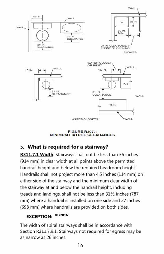
Bathrooms shall have a minimum ceiling height of 6 feet
8 inches (2032 mm) at the center of the front clearance
area for fixtures as shown in Figure R307.1. (See Next
Page)
The ceiling height above fixtures shall be such that the
fixture is capable of being used for its intended purpose.
A shower or tub equipped with a showerhead shall have
a minimum Ceiling height of 6 feet 8 inches (2032 mm)
above a minimum area 30 inches (762 mm) by 30 inches
(762 mm) at the showerhead.
3. Beams and girders spaced not less than 4 feet (1219
mm) on center may project not more than 6 inches (152
mm) below the required ceiling height.
NOTES:_________________________________________
_________________________________________________
_________________________________________________
_________________________________________________
_________________________________________________
_________________________________________________
_________________________________________________
_________________________________________________
_________________________________________________
_________________________________________________
_________________________________________________
_________________________________________________
_________________________________________________
_________________________________________________
_________________________________________________
16
What is required for a stairway?
R311.7.1 Width. Stairways shall not be less than 36 inches
(914 mm) in clear width at all points above the permitted
handrail height and below the required headroom height.
Handrails shall not project more than 4.5 inches (114 mm) on
either side of the stairway and the minimum clear width of
the stairway at and below the handrail height, including
treads and landings, shall not be less than 31½ inches (787
mm) where a handrail is installed on one side and 27 inches
(698 mm) where handrails are provided on both sides.
EXCEPTION: 01/2016
The width of spiral stairways shall be in accordance with
Section R311.7.9.1. Stairways not required for egress may be
as narrow as 26 inches.
17
What are the requirements for smoke alarms?
R314.3 Location. Smoke alarms shall be installed in the
following locations:
A. In each sleeping room.
B. Outside each separate sleeping area in the immediate
vicinity of the bedrooms.
C. On each additional story of the dwelling, including
basements and habitable attics (finished) but not including
crawl spaces, or uninhabitable (unfinished) attics, and
uninhabitable (unfinished) attic stories and uninhabitable
attics. In dwellings or dwelling units with split levels and
without an intervening door between the adjacent levels, a
smoke alarm installed on the upper level shall suffice for
the adjacent lower level provided that the lower level is less
than one full story below the upper level.
When more than one smoke alarm is required to be installed
within an individual dwelling unit the alarm devices shall be
interconnected in such a manner that the actuation of one
alarm will activate all of the alarms in the individual unit.
When and where are CO2 alarms required?
R315.1 Carbon monoxide alarms. All new construction of
one-and two-family dwellings and townhouses within which
fuel-fired appliances or fireplaces are installed or that have
attached garages shall be provided with an approved carbon
monoxide alarm installed outside of each separate sleeping
area in the immediate vicinity of the bedroom(s) as directed
by the alarm manufacturer.
R315.2 Where required-existing dwellings. For existing
dwellings, where interior alterations, repairs or additions
requiring a building permit occur, or where one or more
sleeping rooms are added or created, or where fuel-fired
appliances or fireplaces are added or replaced, carbon
monoxide alarms shall be provided in accordance with
Section 315.1.

18
EXCEPTION: Work involving the exterior surfaces of
dwellings, such as the replacement of roofing or siding, or
the addition or replacement of windows or doors, or the
addition of a porch or deck, or the installation of a fuel-fire
appliance that cannot introduce carbon monoxide to the
interior of the dwelling, are exempt from the requirements of
this section.
R315.3 Alarm requirements. The required carbon
monoxide alarms shall be audible in all bedrooms over
background noise levels with all intervening doors closed.
Single station carbon monoxide alarms shall be listed as
complying with UL 2034 and shall be installed in accordance
with this code and the manufacturer’s installation
instructions. Battery powered, plug-in, or hard-wired alarms
are acceptable for use.
How many vents are required in a
foundation?
R408.1.1 Foundation vent sizing. The minimum net area of
ventilation openings shall be not less than 1 square foot
(0.0929m2) for each 150 square feet (13.9 m
2) of crawl space
ground area.
EXCEPTION:01/2012 The total area of ventilation
openings may be reduced to 1/1,500 of the of the under-
floor area where the ground surface is treated with an
approved vapor retarder material in accordance with
Section R408.2 and the required openings are placed to
provide cross–ventilation of the space. The installation of
operable louvers shall not be prohibited.
NOTES:_________________________________________
_________________________________________________
_________________________________________________
_________________________________________________
_________________________________________________

19
FOOTINGS
When is a footing inspection required?
NCACP 107.1.1 Footing inspections shall be made after the
trenches are excavated, all grade stakes are installed, all
reinforcing steel and supports are in place and appropriately
tied, all necessary forms are in place and braced but before
any concrete is placed.
When is a soil test required?
Section R401.4 A soil test will be required when footings are
excavated in areas likely to have expansive, compressible,
shifting or other unknown soil characteristics. Soil test will
also be required when the existing soils do not meet the
assumed 2000 psf or when the design requires a greater soil
bearing capacity. The building official shall determine if a soil
test is required to determine the soil’s characteristics at a
specific location. This test shall be performed by an
approved agency using an approved method.
Is 2500 psi concrete the minimum allowable
for footings?
Section R402.2 Yes, but only under moderate weather
conditions. See Table R402.2 for other concrete applications.
What is the minimum depth of a footing?
Section R403.1.4 01/2015 All exterior footings and
foundation systems shall extend below the frost line
specified in Table R301.2(1). In no case shall the bottom of
the exterior footings be less than 12 inches below the
undisturbed ground surface or engineered fill finished grade.
EXCEPTION: Frost protected footings constructed in
accordance with Section R403.3 and footings and
foundations erected on solid rock shall not be required
to extend below the frost line.
20
Does a footing need to be level?
Section R403.1.5 The top surface of footings shall be level
(1/2 inch in 10 feet) or shall be brought level, under the
width of the wall, with masonry units with full mortar joints.
The bottom surface of footings may have a slope not
exceeding one-unit vertical in 10 units horizontal (10-percent
slope). Footings shall be stepped where it is necessary to
change the elevation of the top surface of the footings or
where the slope of the bottom surface of the footings will
exceed one-unit vertical in ten units horizontal (10-percent
slope).
Illustration on page 23.
What is the minimum footing size for a
masonry fireplace?
Section R1003.2 Footings for masonry chimneys shall be
constructed of concrete or solid masonry at least 12 inches
(305 mm) thick and shall extend at least 12 inches (305
mm) beyond the face of the foundation or support wall
on all sides. Footings shall be founded on natural
undisturbed earth or engineered fill below frost depth. In
areas not subjected to freezing, footings shall be at least 12
inches (305 mm) below finished grade.
NOTES:_________________________________________
_________________________________________________
_________________________________________________
_________________________________________________
_________________________________________________
_________________________________________________
_________________________________________________
_________________________________________________
_________________________________________________
_________________________________________________
_________________________________________________
21
For SI: 1-inch = 25.4 mm, 1 pound per square foot = 0.0479 kPa.
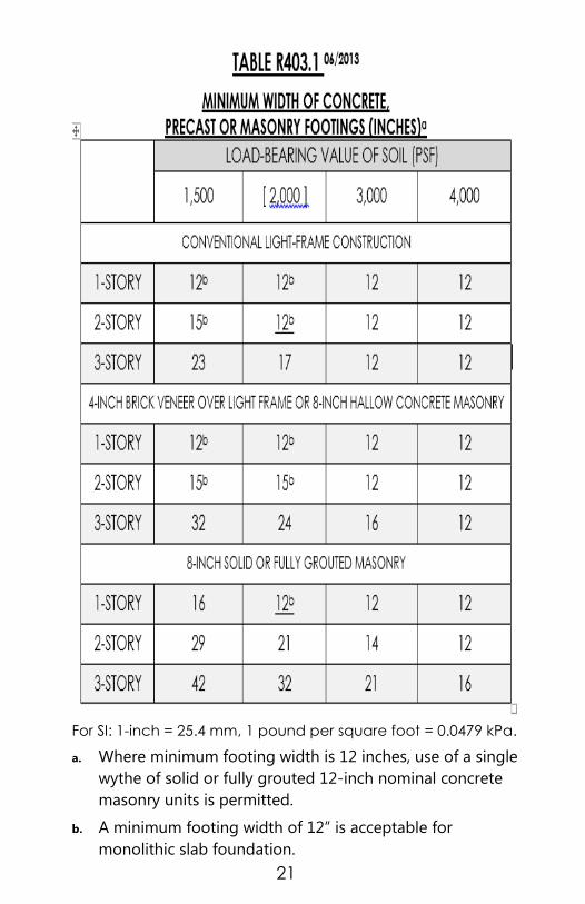
a. Where minimum footing width is 12 inches, use of a single
wythe of solid or fully grouted 12-inch nominal concrete
masonry units is permitted.
b. A minimum footing width of 12” is acceptable for
monolithic slab foundation.

22
TABLE 403.1a
For SI: 1 inch = 25.4 mm, 1 foot = 304.8 mm, 1 pound per square inch
= 6.895 kPa, 1 pound per square foot = 0.0479 kPa.
Pier sizes are based on hollow CMU capped with 4 inches of
solid masonry or concrete for 1 (one) story and 8 inches of
solid masonry or concrete for 2 (two) and 2-1/2 (Two and one
half) story houses or shall have cavities of the top course filled
with concrete or grout or other approved methods. Mortar
shall be Type S.
Footing sizes are based on 2000 psf allowable soil bearing and
2500 psi concrete. This table is based upon the limitations of a
tributary area using dimensional framing lumber only.
Centers of piers shall bear in the middle one-third of the
footings. Girders must have full bearing on piers. Footings shall
be full thickness over the entire area of the footing.
Pier sizes given are minimum. For height/thickness limitations
see Section R606.6.
Area in table is for first level being supported by pier and
footing (square foot).

23
NOTES:__________________________________________________
___________________________________________________________
___________________________________________________________
___________________________________________________________
___________________________________________________________
___________________________________________________________
___________________________________________________________
___________________________________________________________
___________________________________________________________
___________________________________________________________
___________________________________________________________
___________________________________________________________

24
FOUNDATIONS
When is a foundation inspection required?
NCACP Section 107.1.3 To be made after all foundation
supports are installed. This inspection is to check
foundation supports, crawl space leveling, ground
clearances, and positive drainage when required. Do not
backfill footings until after this inspection.
What is the maximum number of stories
allowed to be constructed on a pier and
curtain wall?
Section R404.1.5.3 Not more than 2 stories in height.
What is the maximum unsupported height of
masonry piers?
Section R404.1.5.4 & R606.6 The maximum unsupported
height of hollow masonry piers is 4 times the least
dimension of the pier. For solid masonry piers, the max is 10
times the least dimension of the pier.
Are solid masonry units required to have full
bed and head joints?
Section R607.2.2.1 & R607.2.2.2 All solid or hollow
masonry units shall be laid with full head and bed joints

25
R404.1.6 HEIGHT
ABOVE FINISHED
GRADE.
CONCRETE AND
MASONRY
FOUNDATION
WALLS SHALL
EXTEND ABOVE
THE FINISHED
GRADE ADJACENT
TO THE
FOUNDATION AT
ALL POINTS A
MINIMUM OF 4
INCHES (102 MM)
WHERE MASONRY
VENEER IS USED
AND A MINIMUM
OF 6 INCHES (152
MM) ELSEWHERE.

26
SLABS
When is a slab inspection required? NCACP Section 107.1.2 Under slab inspection is to be made
after all forms, all under slab electrical, plumbing and/or
heating and air conditioning, all crushed stone, vapor retarder,
all reinforcing steel with supports tied and/or all welded wire
fabric is installed, when required, but before any concrete is
placed. All thickened areas and grade beams must be installed.
Verification of termite treatment is required at this time.
EXECEPTION: An inspection is not required for
driveway slabs, patio slabs, sidewalks etc. which are
considered non-habitable spaces.
Are footings required under interior load-
bearing walls in slab on grade construction? Section R403 Yes, footings are required under interior load-
bearing walls and all other load-bearing conditions. See
illustrations on page 24.
When is a 4" base required under slabs and
what material should be used? Section R506.2.2 A 4-inch-thick base course consisting of
clean graded sand, gravel, crushed stone or crushed blast-
furnace slag passing a 2-inch sieve shall be placed on the
prepared sub grade when the slab is below grade.
EXCEPTION: A base course is not required when the
concrete slab is installed on well-drained or sand-gravel
mixture soils classified as Group I according to the
United Soil Classification System in accordance with
Table R405.1 in the International Residential Code.
How much backfill is allowed before a
compaction test would be required? Section R506.2.1 Fill material shall be free of vegetation and
foreign material. The fill shall be compacted to assure
uniform support of the slab, and except where approved, the
fill depths shall not exceed 24 inches (610 mm) for clean
sand or gravel and 8 inches (203 mm) for earth. A
compaction test is required when fill placement exceeds 24"

27
in depth. A compaction test may also be required under
certain soil conditions.
What is the correct lap of a vapor barrier? 01/2015
Section R506.2.3 A 6 mil (0.006 inch; 152 µm) polyethylene
or approved vapor retarder with joints lapped not less than
6 inches (152 mm) shall be placed between the concrete
floor slab and the base course or the prepared subgrade
where no base course exists.
Exception: The vapor retarder may be omitted: From detached garages, utility buildings and other
unheated accessory structures.
For unheated storage rooms having an area of less
than 70 square feet (6.5 m2) and carports.
From driveways, walks, patios and other exterior
flatwork not likely to be enclosed and heated at a
later date.
Where approved by the building official, based on
local site conditions.
From attached garages where floor space at parking
level is unheated.
What is the minimum specified strength (psi)
of concrete for slabs on grade? Table R402.2 Basement slabs and interior slabs on grade
require 2500 psi concrete. Porches, carport slabs and steps
exposed to weather and garage floors require 3000-psi air
entrained concrete.
What is the required attachment for framed
walls for slabs and masonry foundations?
Section R403.1.6 The wood sole plate at exterior walls on
monolithic slabs and masonry foundations shall be anchored to
the foundation with anchor bolts spaced a maximum of 6 feet on
center. Anchor bolts shall also be located within 12 inches of the
corner. Bolts shall be at least 1/2 inch in diameter and shall extend
a minimum of 7 inches into masonry or concrete. There shall be at
minimum two anchors per sill plate. Embedment depth of anchor
straps shall be per manufacturer instructions.

28
Bolting Locations and Installations

29
Bolting Locations and Installations
See Illustration on page 28 in this booklet for Installation
locations for above.
There shall be a minimum of 2 bolts per plate section.
Bolts shall extend a minimum of 7" into masonry or
concrete.
Embedment depth of anchor straps shall be per
manufacturer Instructions.
Fastening schedule are as follows: For Simpson strap
anchors, side nailing 2 – 10d x1 1/2 and 4 –10d x 1 1/2 nail
in top of plate (total). For Hutch strap anchor STA16 (6)10d
on each side (12 total). For Hutch strap anchor STA 18
(4)10d each side (8 total).
NOTE: It is the responsibility of the permit holder to install
the anchors in accordance with the manufacturer
requirements. The above fasteners are approved alternates in
Mecklenburg County. Should you wish to use another
manufacturers’ anchor, you will need to provide the
manufacturers’ installation instructions.
NOTES:________________________________________________________
_________________________________________________________________
_________________________________________________________________
_________________________________________________________________
_________________________________________________________________
_________________________________________________________________
_________________________________________________________________
_________________________________________________________________
TYPES OF BOLTS
OR STRAPS BRAND NAME LOCATION-SPACING
1/2 anchor bolt
w/washer (2) N/A
Within 12" of each corner & 6'
o.c. min 7” embedment
22 3/4" anchor
strap (4)
SIMPSON MAB
23
Per
Manufacturers’ Instructions
14 1/2” anchor
strap (4)
SIMPSON MAB
15
Per
Manufacturers’ Instructions

30
FRAMING
When is, a framing inspection required?
NCACP Section 107.1.5 Framing inspections shall be made
after the roof, walls, ceiling and floor framing is complete
with appropriate blocking, bracing and fire stopping in place.
The following Items must be in place and be visible for
inspection:
Pipes; to check for notching, boring or other
penetrations.
Chimneys and vents; to check for clearances from
combustibles, fire stopping and proper construction.
Windows & doors, flashing for roofs, chimneys and wall
openings.
Insulation baffles; may be required during framing
inspection when insulating a cathedral ceiling and the
1" air space required between insulation and the roof
deck is questionable.
All lintels that are required to be bolted to the framing
for support shall not be covered by any exterior or
interior wall or ceiling finish material before approval.
Work may continue without approval for lintels
supported on masonry or concrete.
Trade rough-ins complete.
House wrap installed
Can a bathroom exhaust fan be vented to the
soffit vent?
Section R303.3 Bathrooms, water closet compartments
and other similar rooms shall be provided with aggregate
glazing area in windows of not less than 3 square feet (0.3
m2), one-half of which must be openable.
EXCEPTION: The glazed areas shall not be required
where artificial light and a mechanical ventilation system are
provided. The minimum ventilation rates shall be 50 cubic
feet per minute (24 L/s) for intermittent ventilation or 20
31
cubic feet per minute (10 L/s) for continuous ventilation.
Ventilation air from the space shall be exhausted directly to
the outside. Bathroom exhausts shall be vented directly to
the outside through an approved cap.
What is the minimum tread depth on a
straight flight of stairs?
Section R311.7.4.2, The minimum tread depth shall be 9
inches (229 mm). The tread depth shall be measured
horizontally between the vertical planes of the foremost
projection of adjacent treads and at a right angle to the
tread’s leading edge. The greatest tread depth within any
flight of stairs shall not exceed the smallest by more than 3/8
inch (9.5 mm). Winder treads shall have a minimum tread
depth of 9 inches (229 mm) measured at a point out 12
inches (305 mm) from the side where the treads are
narrower. Winder treads shall have a minimum tread depth
of 4 inches (102 mm) at any point. Within any flight of stairs,
the greatest winder tread depth at the 12 inch (305 mm)
walk line shall not exceed the smallest by more than 3/8 inch
(9.5 mm).
What are the minimum exit requirements?
Section R311.2 01/2012
; R310.1 & R310.1.1 Egress door. At
least one exterior egress door shall be provided for each
dwelling unit. The egress door shall be side-hinged, and shall
provide a minimum clear width of 32 inches (813mm) when
measured between the face of the door and the stop, with
the door open 90 degrees (1.57 rad). The minimum clear
height of the door opening shall not be less than 78 inches
(1981 mm) in height measured from the top of the threshold
to the bottom of the stop. Other exterior doors shall not be
required to comply with these minimum dimensions. All
interior and egress doors and a minimum of one exterior
egress door shall be readily openable from the side from
which egress is to be made without the use of a key or
special knowledge or effort.

32
R310.1 Basements, habitable attics and every sleeping room
shall have at least one operable emergency escape and
rescue opening. Where basements contain one or more
sleeping rooms, emergency egress and rescue openings shall
be required in each sleeping room. Where emergency escape
and rescue openings are provided, they shall have a sill
height of not more than 44 inches (1118 mm) above the
floor. Where a door opening having a threshold below the
adjacent ground elevation serves as an emergency escape
and rescue opening and is provided with a bulkhead
enclosure, the bulkhead enclosure shall comply with Section
R310.3. Emergency escape and rescue openings with a
finished sill height below the adjacent ground elevation shall
be provided with a window well in accordance with Section
R310.2. Emergency escape and rescue openings shall open
directly into a public way, or to a yard or court that opens to
a public way.
R310.1.1 Minimum opening area. All emergency escape
and rescue openings shall have a minimum net clear
openable area of 4 square feet (0.372 m2). The minimum net
clear opening height shall be 22 inches (558 mm). The
minimum net clear opening width shall be 20 inches (508
mm). Emergency escape and rescue openings must have a
minimum total glazing area of not less than 5 square feet
(0.465 m2)
in the case of a ground floor level window and
not less than 5.7 square feet (0.530 m2) in the case of an
upper story window. The net clear opening dimensions
required by this section shall be obtained by the normal
operation of the emergency escape and rescue opening
from the inside.
NOTES:________________________________________________________
________________________________________________________________
________________________________________________________________
________________________________________________________________
________________________________________________________________

33
Does a wood column supporting a beam in a
basement need to be attached?
Section 407.3 Yes. The columns shall be restrained to
prevent lateral displacement at the top and bottom ends.
Wood columns shall not be less in nominal size than 4 inches
by 4 inches (102 mm by 102 mm). Steel columns shall not be
less than 3-inch-diameter (76 mm) Schedule 40 pipe
manufactured in accordance with ASTM A 53 Grade B or
approved equivalent.
EXCEPTION: In Seismic Design Categories A, B and C,
columns no more than 48 inches (1219 mm) in height on a
pier or footing are exempt from the bottom end lateral
displacement requirement within under-floor areas enclosed
by a continuous foundation.
How much can a stud be notched or drilled?
Section R602.6 Notching- Any stud in an exterior wall or
bearing partition may be cut or notched to a depth not
exceeding 25 percent of its width. Studs in nonbearing
partitions may be notched to a depth not to exceed 40
percent of a single stud width. Notching of bearing studs
shall be on one edge only and not to exceed one-fourth the
height of the stud. Notching shall not occur in the bottom or
top 6 inches (152 mm) of bearing studs.
Section R602.6 Drilling- Any single stud may be bored or
drilled, provided that the diameter of the resulting hole is no
more than 60 percent of the stud width, the edge of the hole
is no more than 5/8 inch (16 mm) to the edge of the stud,
and the hole shall not be closer than 6 inches (152 mm) from
an adjacent hole or notch. Holes not exceeding 3/4 inch (19
mm) diameter can be as close as 1-1/2 inches (38.1 mm) on
center spacing. Studs located in exterior walls or bearing
partitions drilled over 40 percent and up to 60 percent shall
also be doubled with no more than two successive doubled
studs bored. See Figures R602.6(1) and R602.6(2).

34
How do I repair the top plates of an exterior
wall when drilled OR notched?
R602.6.1 Drilling and notching of top plate. When piping or
ductwork is placed in or partly in an exterior wall or interior
load-bearing wall, necessitating cutting, drilling or notching
of the top plate by more than 50 percent of its width, a
galvanized metal tie not less than 0.054-inch-thick (1.37 mm)
(16 ga) and 1-1/2 inches (38 mm) wide shall be fastened
across and to the plate at each side of the opening with not
less than eight - 10d (0.148 inch diameter) nails having a
minimum length of 1-1/2 inches (38 mm) at each side or
equivalent. The metal tie must extend a minimum of 6 inches
past the opening. See Figure R602.6.1.
Exception: When the entire side of the wall with the notch
or cut is covered by wood structural panel sheathing.

35
FIGURE R602.6(1)
NOTCHING AND BORED HOLE LIMITATIONS FOR EXTERIOR WALL AND BEARING WALLS

36
FIGURE R602.6(2)
NOTCHING AND BORED HOLE LIMITATIONS FOR INTERIOR NONBEARING WALLS

37
The code requires a double floor joist under
load-bearing partitions that run parallel to
the joist. Can this double joist be separated
to allow piping?
Section R502.4 Yes. Joists under parallel bearing partitions
shall be of adequate size to support the load. The code does
allow the joists to be spaced apart to accommodate pipes,
ducts, vents; however, the joists shall be full depth solid
blocked with lumber not less than 2-inches in nominal
thickness spaced not more than 4 feet on center.
Can single, double, or triple floor joists, be
drilled in center third of the span?
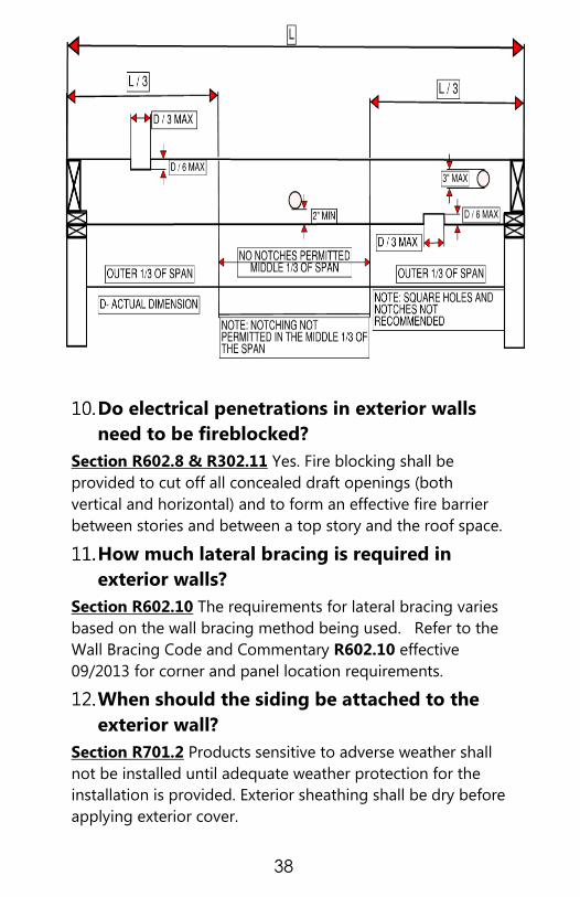
Section R502.8 There are restrictions on the size of the hole
and where drilling is permitted. Structural floor members
shall not be cut, bored, or notched in excess of the
limitations specified. See table below and illustration on
page 38.
LUMBER SIZES AND THEIR ALLOWANCES
JOIST SIZE MAX HOLE MAX NOTCH
DEPTH
MAX END
NOTCH
2X4 NONE NONE NONE
2X6 1-1/2” 7/8” 1-3/8”
2X8 2-3/8” 1-1/4” 1-7/8”
2X10 3 1-1/2” 2-3/8
2X12 3-3/4” 1-7/8” 2-7/8”
38
Do electrical penetrations in exterior walls
need to be fireblocked?
Section R602.8 & R302.11 Yes. Fire blocking shall be
provided to cut off all concealed draft openings (both
vertical and horizontal) and to form an effective fire barrier
between stories and between a top story and the roof space.
How much lateral bracing is required in
exterior walls?
Section R602.10 The requirements for lateral bracing varies
based on the wall bracing method being used. Refer to the
Wall Bracing Code and Commentary R602.10 effective
09/2013 for corner and panel location requirements.
When should the siding be attached to the
exterior wall?
Section R701.2 Products sensitive to adverse weather shall
not be installed until adequate weather protection for the
installation is provided. Exterior sheathing shall be dry before
applying exterior cover.
39
Where is flashing required on brick veneer
finishes?
Section R703.7.5 Flashing of 6 mil (0.152 mm) poly or other
corrosion-resistive material shall be located beneath the first
course of masonry above finished ground level above the
foundation wall or slab and at other points of support,
including structural floors, shelf angles and lintels when
masonry veneers are designed in accordance with Section
R703.7. Top of base flashing shall be installed with a
minimum 2-inch (51 mm) lap behind building paper or
water-repellent sheathing. See Section R703.8 for additional
requirements.
Is bridging required at mid span of floor
joists?
Section R502.7.1 Joists exceeding a nominal 2 inches by 12
inches (51 mm by 305 mm) shall be supported laterally by
solid blocking, diagonal bridging (wood or metal), or a
continuous 1-inch-by-3-inch (25.4 mm by 76 mm) strip
nailed across the bottom of joists perpendicular to joists at
intervals not exceeding 8 feet (2438 mm).
Exception: Trusses, structural composite lumber, structural
glued-laminated members and I-joists shall be supported
laterally as required by the manufacturer’s
recommendations.
The code requires hangers on the double
trimmer joist at floor openings to support
the header and/or girder when the member
spans more than 6 feet. What is required
when those members are less than 6 feet?
Section R502.10 Openings in floor framing shall be framed
with a header and trimmer joists. When then header joist
span does not exceed 4 feet (1219 mm), the header joist may

40
be a single member the same size as the floor joist. Single
trimmer joists may be used to carry a single header joist that
is located within 3 feet (914 mm) of the trimmer joist
bearing. When the header joist span exceeds 4 feet (1219
mm), the trimmer joists and the header joist shall be doubled
and of sufficient cross section to support the floor joists
framing into the header. Approved hangers shall be used for
the header joist to trimmer joist connections when the
header joist span exceeds 6 feet (1829 mm). Hangers or
ledgers are required for header joist spans. Tail joists over
12 feet (3658 mm) long shall be supported at the header by
framing anchors or on ledger strips not less than 2 inches by
2 inches (51 mm by 51 mm).
In the design of truss construction, what are
the drilling and notching requirements?
Section R502.11.3 Truss members and components shall
not be cut, notched, spliced or otherwise altered in any way
without the approval of a registered design professional.
How can a roof be framed for a cathedral
ceiling?
Section 802.3.1 When rafters are used to create a cathedral
ceiling; one method would be to design a ridge beam with
proper support at each end to carry the roof loads. These
loads will have direct bearing that is carried down to
footings. Another method would be an engineered truss
application for a roof system.
Can you explain Figure R802.5.1 braced
rafter construction in The North Carolina
Residential Code?
Figure R802.5.1 This application needs to be used when the
rafters are over spanned. Use the span tables R802.5.1 (1)
and R802.5.1 (2) to check rafter spans. See Pages 66-69
Remember, span is always measured horizontally, not along
rafter length.

41
The purlin or single ply header must be the same size as the
rafter. The 2 x 4 down brace may have a maximum unbraced
length of 8 feet. If brace exceeds 8 feet, it must be laterally
braced at mid-point or may be T-braced. See Illustration on
p.70.
What roof pitch would not require an
underlayment?
Chapter 9 This chapter deals with several types of roof
coverings. All roof covering would require an underlayment
unless the manufacturer’s instructions do not require one.
Can the underlayment be installed running
up the pitch of the roof?
Section R905.2.7 No, per this section the underlayment shall
be applied shingle fashion, parallel to and starting from the
eave.
Which is the proper way to run the starter
course for asphalt shingles?
Section R905 Installation shall be installed per
manufacturer’s instructions. It is common for manufacturers
to require you to cut the tabs off the ends of shingles so the
cement strip is located at the edge of the eaves. Check with
manufacturer to assure proper installation.
Can a standard brick lintel be used at the
fireplace opening?
Section R1001.7 Yes, as long as the lintel is noncombustible
and capable of supporting imposed loads.
NOTES:______________________________________________________
_________________________________________________________________
_________________________________________________________________
_________________________________________________________________
_________________________________________________________________
____________________________________________________________

42
TABLE R-602.3(5)
SIZE, HEIGHT AND SPACING OF WOOD STUDS a,d
For SI: 1 inch = 25.4 mm, 1 foot = 304.8 mm, 1 square foot =
0.093m2.
a. Listed heights are distances between points of lateral support
placed perpendicular to the plane of the wall. Increases in
unsupported height are permitted where justified by analysis.
b. Shall not be used in exterior walls.
c. A habitable attic assembly supported by 2 X 4 studs is limited
to a roof span of 32 feet. Where the roof span exceeds 32 feet,
the wall studs shall be increased to 2 X 6 or the studs shall be
designed in accordance with accepted engineering practice.
d. One half of the studs interrupted by a wall opening shall
be placed immediately outside the jack studs on each side
of the opening as king studs to resist wind loads. King
studs shall extend full height from sole plate to top plate
of the wall.
STU
D S
IZES
(IN
CH
ES)
BEARING WALLS
LA
TER
ALY
UN
SU
PPO
RTED
STU
D H
EIG
HT a
MA
XIM
UM
SP
AC
ING
WH
EN
SU
PPO
RTIN
G
A R
OO
F-C
EIL
ING
ASSEM
BLY
OR
A
HA
BIT
AB
LE A
TTIC
ASSEM
BLY, O
NLY
(IN
CH
ES)
MA
XIM
UM
SP
AC
ING
WH
EN
SU
PPO
RTIN
G
ON
E F
LOO
R, PLU
S A
RO
OF-C
EIL
ING
ASSEM
BLY
OR
A H
AB
ITA
BLE A
TTIC
ASSEM
BLS
(I
NC
HES)
MA
XIM
UM
SP
AC
ING
WH
EN
SU
PPO
RTIN
G
TW
O F
LOO
RS, PLU
S A
RO
OF-C
EIL
ING
ASSEM
BLY
OR
A H
AB
ITA
BLE A
TTIC
ASSEM
BLY
(I
NC
HES)
MA
XIM
UM
SP
AC
ING
WH
EN
SU
PPO
RTIN
G O
NE F
LOO
R H
EIG
HT (F
EET)
LA
TER
ALLY
UN
SU
PPO
RTED
STU
D H
EIG
HT
(FEET)
MA
XIM
UM
SP
AC
ING
(IN
CH
ES)
2X3b --- --- --- --- --- 10 16
2X4 10 24c 16c --- 24 14 24
3X4 10 24 24 16 24 14 24
2X5 10 24 24 --- 24 16 24
2X6 10 24 24 16 24 20 24

43
TABLE R602.3(1)- WALL FRAMING a, e
CONNECTIONb
(NAIL SIZE AND POSITION
EXAGGERATED
FOR ILLUSTRATIVE PURPOSES)
FASTENER
MINIMUM NOMINAL LENGTH IN
INCHES
X MINIMUM NOMINAL NAIL
DIAMETER IN INCHES
QUANTITY PER
CONNECTION,
ORSPACING
BETWEEN
FASTENERSd
3-1/2" × 0.162" nail(16dcommon)c 3
3" × 0.148" nail (10d common) 4
3-1/4" × 0.131" nail
5
3" × 0.131" nail
3-1/4" × 0.120" nail
3" × 0.120" nail
2-1/2" × 0.131" nail (8d common)c 4
3-1/2"×0.162"nail (16d common) 3
3" × 0.148" nail (10d common)
4
3-1/4" × 0.131" nail
3" × 0.131" nail
3-1/4" × 0.120" nail
3" × 0.120" nail
2-3/8" × 0.113" nail
5
2" × 0.113" nail
2-1/4" × 0.105" nail
2-1/4" × 0.099" nail
3-1/2"×0.162"nail (16d common)c
2 EACH
SIDE OF LAP 3" × 0.148" nail
3-1/4" × 0.131" nail
3 EACH
SIDEOF LAP
3" × 0.131" nail
3-1/4" × 0.120" nail
3" × 0.120" nail
2-1/2" × 0.131" nail (8d common)c
2
3-1/2"×0.162"nail (16d common)
3" × 0.148" nail (10d common)
3-1/4" × 0.131" nail
3" × 0.131" nail
3-1/4" × 0.120" nail
3 3" × 0.120" nail
2-3/8" × 0.113" nail
2" × 0.113" nail
4 2-1/4" × 0.105" nail
2-1/4" × 0.099" nail
3-1/2" × 0.135" nail (16d BOX)C 3 PER 16” SPACE
3-1/2" × 0.162" nail (16d common) 2 PER 16” SPACE
3" × 0.148" nail (10d common) 3 PER 16” SPACE
3-1/4" × 0.131" nail
3" × 0.131" nail
4 PER 16” SPACE 3-1/4" × 0.120" nail
3" × 0.120" nail
3-1/2" × 0.162" nail (16dcommon)C 16” o.c
3" × 0.148" nail (10d common)
8” o.c
3-1/4" × 0.131" nail
3" × 0.131" nail
3-1/4" × 0.120" nail
3" × 0.120" nail

44
TABLE R602.3(1)- CONTINUED WALL FRAMING CONNECTIONb
(NAIL SIZE AND
POSITION EXAGGERATED
FOR ILLUSTRATIVE
PURPOSES)
FASTENER
MINIMUM NOMINAL LENGTH IN INCHES
X MINIMUM NOMINAL NAIL DIAMETER
IN INCHES
QUANTITY PER
CONNECTION
OR
SPACING
BETWEEN
FASTENERSd
3" × 0.148" nail (10d common)c
16” o.c 3-1/2" × 0.162" nail (16dcommon)
3-1/4" × 0.131" nail 12” o.c 3" × 0.131" nail
3-1/4" × 0.120" nail
3" × 0.120" nail
3" × 0.148" nail (10d common)c 12” o.c 3-1/2" × 0.162" nail (16dcommon)
3-1/4" × 0.131" nail 8” o.c 3" × 0.131" nail
3-1/4" × 0.120" nail
3" × 0.120" nail
3-1/2" × 0.162" nail (16dcommon)c 24” o.c
3" × 0.148" nail (10d common) 16” o.c 3-1/4" × 0.131" nail
3" × 0.131" nail
3-1/4" × 0.120" nail 12” o.c 3" × 0.120" nail
NOTES:_________________________________________
_________________________________________________
_________________________________________________
_________________________________________________
_________________________________________________
_________________________________________________
_________________________________________________
_________________________________________________
_________________________________________________
_________________________________________________
_________________________________________________
_________________________________________________
_________________________________________________
_________________________________________________
_________________________________________________
_________________________________________________
45
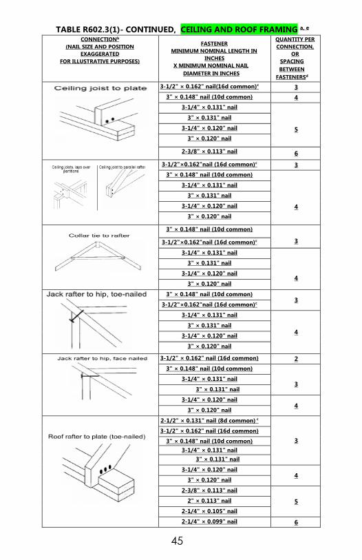
TABLE R602.3(1)- CONTINUED, CEILING AND ROOF FRAMING a, e
CONNECTIONb
(NAIL SIZE AND POSITION
EXAGGERATED
FOR ILLUSTRATIVE PURPOSES)
FASTENER
MINIMUM NOMINAL LENGTH IN
INCHES
X MINIMUM NOMINAL NAIL
DIAMETER IN INCHES
QUANTITY PER
CONNECTION,
OR
SPACING
BETWEEN
FASTENERSd
3-1/2" × 0.162" nail(16d common)c 3
3" × 0.148" nail (10d common) 4
3-1/4" × 0.131" nail
5
3" × 0.131" nail
3-1/4" × 0.120" nail
3" × 0.120" nail
2-3/8" × 0.113" nail 6
3-1/2"×0.162"nail (16d common)c 3
3" × 0.148" nail (10d common)
4
3-1/4" × 0.131" nail
3" × 0.131" nail
3-1/4" × 0.120" nail
3" × 0.120" nail
3" × 0.148" nail (10d common)
3 3-1/2"×0.162"nail (16d common)c
3-1/4" × 0.131" nail
4
3" × 0.131" nail
3-1/4" × 0.120" nail
3" × 0.120" nail
3" × 0.148" nail (10d common) 3
3-1/2"×0.162"nail (16d common)c
3-1/4" × 0.131" nail
4 3" × 0.131" nail
3-1/4" × 0.120" nail
3" × 0.120" nail
3-1/2" × 0.162" nail (16d common) 2
3" × 0.148" nail (10d common)
3 3-1/4" × 0.131" nail
3" × 0.131" nail
3-1/4" × 0.120" nail 4
3" × 0.120" nail
2-1/2" × 0.131" nail (8d common) c
3
3-1/2" × 0.162" nail (16d common)
3" × 0.148" nail (10d common)
3-1/4" × 0.131" nail
3" × 0.131" nail
3-1/4" × 0.120" nail 4
3" × 0.120" nail
2-3/8" × 0.113" nail
5 2" × 0.113" nail
2-1/4" × 0.105" nail
2-1/4" × 0.099" nail 6
46
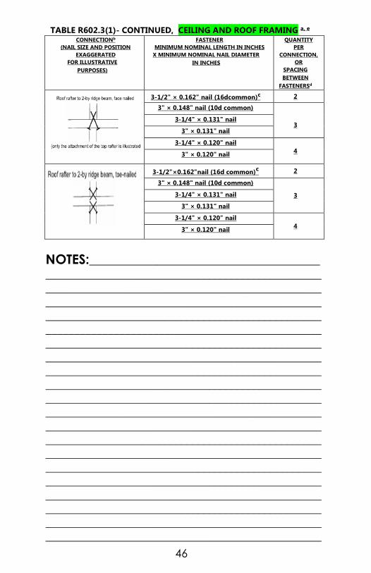
TABLE R602.3(1)- CONTINUED, CEILING AND ROOF FRAMING a, e
CONNECTIONb
(NAIL SIZE AND POSITION
EXAGGERATED
FOR ILLUSTRATIVE
PURPOSES)
FASTENER
MINIMUM NOMINAL LENGTH IN INCHES
X MINIMUM NOMINAL NAIL DIAMETER
IN INCHES
QUANTITY
PER
CONNECTION,
OR
SPACING
BETWEEN
FASTENERSd
3-1/2" × 0.162" nail (16dcommon)c 2
3" × 0.148" nail (10d common)
3 3-1/4" × 0.131" nail
3" × 0.131" nail
3-1/4" × 0.120" nail
4 3" × 0.120" nail
3-1/2"×0.162"nail (16d common)c 2
3" × 0.148" nail (10d common)
3 3-1/4" × 0.131" nail
3" × 0.131" nail
3-1/4" × 0.120" nail
4 3" × 0.120" nail
NOTES:_________________________________________
_________________________________________________
_________________________________________________
_________________________________________________
_________________________________________________
_________________________________________________
_________________________________________________
_________________________________________________
_________________________________________________
_________________________________________________
_________________________________________________
_________________________________________________
_________________________________________________
_________________________________________________
_________________________________________________
_________________________________________________
_________________________________________________
_________________________________________________
_________________________________________________
_________________________________________________
_________________________________________________

47
TABLE R602.3(1)- CONTINUED, CEILING AND ROOF FRAMING a, e
CONNECTIONb
(NAIL SIZE AND POSITION
EXAGGERATED
FOR ILLUSTRATIVE
PURPOSES)
FASTENER
MINIMUM NOMINAL LENGTH IN INCHES
X MINIMUM NOMINAL NAIL DIAMETER IN
INCHES
QUANTITY PER
CONNECTION,
OR SPACING
BETWEEN
FASTENERSd
3-1/2" × 0.162" nail (16d common)c 3
3" × 0.148" nail (10d common) 5
3-1/4" × 0.131" nail
6
3" × 0.131" nail
3-1/4" × 0.120" nail
3" × 0.120" nail
3-1/2"×0.162"nail (16d common)c 3
3" × 0.148" nail (10d common)
4
3-1/4" × 0.131" nail
3" × 0.131" nail
3-1/4" × 0.120" nail
3" × 0.120" nail
2-1/2" × 0.131" nail (8d common)c
3 3" × 0.148" nail (10d common)
3-1/4" × 0.131" nail
3" × 0.131" nail
4 3-1/4" × 0.120" nail
3" × 0.120" nail
2-1/2" × 0.131" nail (8d common)c 2
3-1/4" × 0.120" nail
3 3" × 0.120" nail
2-3/8" × 0.113" nail
2" × 0.113" nail (6d common) 4
2-1/4" × 0.105" nail 3
2-1/4" × 0.099" nail 4
2-1/2" × 0.113" (3d box)c 6" o.c.
3-1/2" × 0162" nail (16d common) 8" o.c.
3" × 0.148" nail (10d common)
4" o.c.
3-1/4" × 0.131" nail
3" × 0.131" nail
3-1/4" × 0.120" nail
3" × 0.120" nail 4" o.c.
2-3/8" × 0.113" nail 4" o.c.
2" × 0.113" nail (6d common)
3" o.c.
2-1/4" × 0.105" nail
2-1/4" x 0.099" nail

48
TABLE R602.3(1)- CONTINUED, CEILING AND ROOF FRAMING a, e
CONNECTIONb
(NAIL SIZE AND POSITION
EXAGGERATED
FOR ILLUSTRATIVE
PURPOSES)
FASTENER
MINIMUM NOMINAL
LENGTH IN INCHES
X MINIMUM NOMINAL
NAIL DIAMETER IN
INCHES
SPACING OF
FASTENERS
ALONG THE
TOP AND
BOTTOM OF
THE BEAM,
STAGGERED
ON EACH
SIDE OF EACH
LAYER
NUMBER OF
FASTENERS
AT EACH
END AND
SPLICE FOR
EACH LAYER
4" × 0.192" nail
(20d common)c
32" o.c. 2
3-1/2" × 0.162" nail
(16d common)
24" o.c.
3 3" × 0.148" nail
(10d common)
3-1/4" × 0.131" nail
3" × 0.131" nail
3-1/4" × 0.120" nail 16" o.c. 3
3" × 0.120" nail
2-1/2" × 0.131" nail
(8d common)
16" o.c. 4
For SI: 1 inch = 25.4 mm, 1 mile per hour = 0.44 m/s, 1 foot = 304.8 mm.
a. This fastening schedule applies to framing members having an actual
thickness of 1-1/2" (nominal “2-by” lumber).
b. Fastenings listed above may also be used for other connections that are
not listed but that have the same configuration and the same code
requirement for fastener quantity/spacing and fastener size
(pennyweight and style, e.g., 8d common, “8-penny common nail”).
c. This fastener, in the quantity or spacing shown in the rightmost column,
comprises the most stringent fastening of the connection listed in the
International, National, International One- and Two-family Dwelling,
International Residential, Standard or Uniform Building Codes.
d. Fastening schedule only applies to buildings of conventional wood
frame construction where wind or seismic analysis is not required by the
applicable code. In areas where wind or seismic analysis is required,
required fastening must be determined by structural analysis. The
following are conditions for which codes require structural analysis:
i. For nominal dimensions of nails see Table R602.3(1a)
ii. North Carolina Residential Code – buildings located in areas where
the design wind speed equals or exceeds 110 mph (177.1 km/h) (3
second gust) or assigned to seismic design categories C, D1 and D2
(with detached one- and two-family dwellings in category C being
exempt).
e. Reprinted by permission of the ICC Evaluation Service, LLC from
Evaluation Report ESR-1539.

49
TABLE R602.3(1)- CONTINUED
FASTENER SCHEDULE FOR STRUCTURAL MEMBERS j
DESCRIPTION
OF BUILDING
MATERIALS
DESCRIPTION OF FASTENERS b, c, e
SPACING OF
FASTENERS
EDGES
(INCHES) i
INTERMEDIATE SUPPORTS
c, e
(INCHES)
WOOD STRUCTURAL PANNELS, SUBFLOOR, ROOF AND INTERIOR WALL SHEATHING TO
FRAMING AND PARTICLEBOARD WALL SHEATHING TO FRAMING
3/8” - 1/2 “
6d common (2″ × 0.113″) nail (subfloor
wall)
8d common (2-1/2″ × 0.131″) nail
(roof)f
6 12 g
19/32”- 1” 8d common nail (2-1/2″ × 0.131″) 6 12 g
1-1/8” - 1-
1/4"
10d common (3″ × 0.148″) nail or
8d (2-1/2″ × 0.131″) deformed nail 6 12
OTHER WALL SHEATHING h
1/2” structural
cellulosic
fiberboard
sheathing
1-1/2” galvanized roofing nail, 7/16”
crown or 1” crown staple 16 ga., 1-1/4”
long 3 6
25/32”
structural
cellulosic
fiberboard
sheathing
1-3/4” galvanized roofing nail, 7/16”
crown or 1” crown staple 16 ga., 1-
1/2” long 3 6
1/2”gypsum
sheathingd
1-1/2” galvanized roofing nail, staple
galvanized, 1-1/2” long; 1-1/4”
screws,
Type W or S
7 7
5/8”gypsum
sheathingd
1-3/4” galvanized roofing nail, staple
galvanized, 1-5/8” long; 1-5/8”
screws,
Type W or S
7 7
WOOD STRUCTURAL PANELS, COMBINATION SUBFLOOR UNDERLAYMENT
TO FRAMING
3/4" and
less
6d deformed (2″ × 0.120″) nail or
8d common (2-1/2″ × 0.131″) nail 6 12
7/8” – 1” 8d common (2-1/2″ × 0.131″) nail or
8d deformed (2-1/2″ × 0.120″) nail 6 12
1-1/8” – 1-
1/4”
10d common (3″ × 0.148″) nail or
8d deformed (2-1/2″ × 0.120″) nail 6 12
For SI: 1 inch = 25.4 mm, 1 foot = 304.8 mm, 1 mile per hour = 0.447 m/s; 1ksi = 6.895 MPa.
a. Deleted.
b. Staples are 16 gage wire and have a minimum 7/16-inch on diameter
crown width.
c. Nails shall be spaced at not more than 6 inches on center at all supports
where spans are 48 inches or greater.
d. Four-foot-by-8-foot or 4-foot-by-9-foot panels shall be applied
vertically.

50
e. Spacing of fasteners not included in this table shall be based on Table
R602.3(2).
f. For regions having basic wind speed of 110 mph or greater, 8d
deformed (21/2" × 0.120) nails shall be used for attaching plywood and
wood structural panel roof sheathing to framing within minimum 48-
inch distance from gable end walls, if mean roof height is more than 25
feet, up to 35 feet maximum.
g. For regions having basic wind speed of 100 mph or less, nails for
attaching wood structural panel roof sheathing to gable end wall
framing shall be spaced 6 inches on center. When basic wind speed is
greater than 100 mph, nails for attaching panel roof sheathing to
intermediate supports shall be spaced 6 inches on center for minimum
48-inch distance from ridges, eaves and gable end walls; and 4 inches
on center to gable end wall framing.
h. Gypsum sheathing shall conform to ASTM C 79 and shall be installed in
accordance with GA 253. Fiberboard sheathing shall conform to ASTM C
208.
i. Spacing of fasteners on floor sheathing panel edges applies to panel
edges supported by framing members and required blocking and at all
floor perimeters only. Spacing of fasteners on roof sheathing panel
edges applies to panel edges supported by framing members and
required blocking. Blocking of roof or floor sheathing panel edges
perpendicular to the framing members need not be provided except as
required by other provisions of this code. Floor perimeter shall be
supported by framing members or solid blocking. Roof sheathing 7/16-
inch or greater in thickness does not require perimeter blocking.
j. For nominal dimensions of nails see Table R602.3(1a).
NOTES:_________________________________________
_________________________________________________
_________________________________________________
_________________________________________________
_________________________________________________
_________________________________________________
_________________________________________________
_________________________________________________
_________________________________________________
_________________________________________________
_________________________________________________
_________________________________________________
_________________________________________________
_________________________________________________

51
TABLE R602.3(2)ALTERNATE ATTACHMENTS NOMINAL
MATERIAL
THICKNESS
(INCHES)
DESCRIPTION a, b OF FASTENERS
SPACING c OF FASTENERS
EDGES
(INCHES)
INTERMEDIATE
SUPPORTS
(INCHES)
WOOD STRUCTURAL PANNELS, SUBFLOOR, ROOF AND INTERIOR WALL SHEATHING TO
FRAMING AND PARTICLEBOARD WALL SHEATHING TO FRAMING f
up to 1/2"
Staple 15 ga. 1-3/4” 4 8
0.097 - 0.099 Nail 2-1/4” 3 6
Staple 16 ga. 1-3/4” 3 6
19/32” and
5/8”
0.113 Nail 2” 3 6
Staple 15 and 16 ga. 2” 4 8
0.097 - 0.099 Nail 2-1/4” 4 8
23/32” and
3/4”
Staple 14 ga. 2” 4 8
Staple 15 ga. 1-3/4” 3 6
0.097 - 0.099 Nail 2-1/4” 4 8
Staple 16 ga. 2” 4 8
1”
Staple 14 ga. 2-1/4” 4 8
0.113 Nail 2-1/4” 3 6
Staple 15 ga. 2-1/4” 4 8
0.097 - 0.099 Nail 2-1/2’ 4 8
NOMINAL
MATERIAL
THICKNESS
(inches)
DESCRIPTION a,b OF FASTENER AND
LENGTH (inches)
SPACING c OF FASTENERS
Edges (inches)
Body of panel d
(inches)
Floor underlayment; plywood-hardboard-particleboard f
Plywood
1/4" and
5/16”
1-1/4” ring or screw shank nail-minimum
12- 1/2 ga. (0.099″) shank diameter 3 6
Staple 18 ga., 7/8, 3/16 crown width 2 5
11/32”,
3/8”,
15/32”, and
1/2"
1-1/4” ring or screw shank nail-minimum
12- 1/2 ga. (0.099″) shank diameter 6 8 e
19/32”,
5/8”,
23/32” and
3/4"
1-1/2” ring or screw shank nail-minimum
12- 1/2 ga. (0.099″) shank diameter 6 8
Staple 16 ga. 1-1/2” 6 8
Hardboard f
0.200
1-1/2” long ring-grooved underlayment
nail 6 6
4d cement-coated sinker nail 6 6
Staple 18 ga., 7/8” long (plastic coated) 3 6
Particleboard
1/4" 4d ring-grooved underlayment nail 3 6
Staple 18 ga., 7/8” long, 3/16” crown 3 6
3/8” 6d ring-grooved underlayment nail 6 10
Staple 16 ga., 1-1/8” long, 3/8” crown 3 6
1/2", 5/8” 6d ring-grooved underlayment nail 6 10
Staple 16 ga., 1-5/8” long, 3/8” crown 3 6
For SI: 1 inch = 25.4 mm.
a. Nail is a general description and may be T-head, modified round head or round head.
b. Staples shall have a minimum crown width of 7/16-inch on diameter except as noted.
c. Nails or staples shall be spaced at not more than 6 inches on center at all supports where
spans are 48 inches or greater. Nails or staples shall be spaced at not more than 12 inches
on center at intermediate supports for floors.
d. Fasteners shall be placed in a grid pattern throughout the body of the panel.
e. For 5-ply panels, intermediate nails shall be spaced not more than 12 inches on center
each way.
f. Hardboard underlayment shall conform to ANSI/AHA A135.4.

52
Table R502.5(1) #1 SYP OR BETTER
GIRDER SPANS a,b AND HEADER SPANS a,b FOR EXTERIOR BEARING WALLS
(Max spans for Doug fir-larch, hem-fir, southern pine and spruce-pine-fir b and required # of jack studs)
GIRDER AND
HEADER
SUPPORTS
SIZE
GROUND SNOW LOAD (psf)e
30
Building Widthc Feet
20 28 36
Span NJ d Span NJ
d Span NJ
d
Roof and
ceiling
2-2x4 3-6 1 3-2 1 2-10 1
2-2x6 5-5 1 4-8 1 4-2 1
2-2x8 6-10 1 5-11 2 5-4 2
2-2x10 8-5 2 7-3 2 6-6 2
2-2x12 9-9 2 8-5 2 7-6 2
3-2x8 8-4 1 7-5 1 6-8 1
3-2x10 10-6 1 9-1 2 8-2 2
3-2x12 12-2 2 10-7 2 9-5 2
4-2x8 9-2 1 8-4 1 7-8 1
4-2x10 11-8 1 10-6 1 9-5 2
4-2x12 14-1 1 12-2 2 10-
11
2
Roof, ceiling
and one
center
bearing floor
2-2x4 3-I 1 2-9 1 2-5 1
2-2x6 4-6 1 4-0 1 3-7 2
2-2x8 5-9 2 5-0 2 4-6 2
2-2x10 7-0 2 6-2 2 5-6 2
2-2x12 8-1 2 7-1 2 6-5 2
3-2x8 7-2 1 6-3 2 5-8 2
3-2x10 8-9 2 7-8 2 6-11 2
3-2x12 10-2 2 8-11 2 8-0 2
4-2x8 8-1 1 5-2 2 4-8 2
4-2x10 10-1 1 8-10 2 8-0 2
4-2x12 11-9 2 10-3 2 9-3 2
CONTINUED►

53
Table R502.5(1) #1 SYP OR BETTER
GIRDER SPANS a,b AND HEADER SPANS
a,b FOR EXTERIOR BEARING WALLS
(Max spans for Doug fir-larch, hem-fir, southern pine and spruce-pine-fir b and required # of jack studs)
GIRDER AND
HEADER
SUPPORTS
SIZE
GROUND SNOW LOAD (psf)e
30
Building Widthc Feet
20 28 36
Span NJ d Span NJ
d Span NJ
d
Roof, ceiling
and one clear
span floor
**USE FOR
DECKS**
2-2x4 2-8 1 2-4 1 2-1 1
2-2x6 3-11 1 3-5 2 3-0 2
2-2x8 5-0 2 4-4 2 3-10 2
2-2x10 6-1 2 5-3 2 4-8 2
2-2x12 7-1 2 6-1 3 5-5 3
3-2x8 6-3 2 5-5 2 4-10 2
3-2x10 7-7 2 6-7 2 5-11 2
3-2x12 8-10 2 7-8 2 6-10 2
4-2x8 7-2
1 6-3 2 5-7 2
4-2x10 8-9 2 7-7 2 6-10 2
4-2x12 10-2 2 8-10 2 7-11 2
Roof, ceiling
and two
center-
bearing floors
2-2x4 2-7 1 2-3 1 2-0 1
2-2x6 3-9 2 3-3 2 2-11 2
2-2x8 4-9 2 4-2 2 3-9 2
2-2x10 5-9 2 5-1 2 4-7 3
2-2x12 6-8 2 5-10 3 5-3 3
3-2x8 5-11 2 5-2 2 4-8 2
3-2x10 7-3 2 6-4 2 5-8 2
3-2x12 8-5 2 7-4 2 6-7 2
4-2x8 4-10 2 4-3 2 3-10 2
4-2x10 8-4 2 7-4 2 6-7 2
4-2x12 9-8 2 8-6 2 7-8 2
CONTINUED►

54
Table R502.5(1) #1 SYP OR BETTER
GIRDER SPANS a,b AND HEADER SPANS
a,b FOR EXTERIOR BEARING WALLS
(Max spans for Doug fir-larch, hem-fir, southern pine and spruce-pine-fir b and required # of jack studs)
GIRDER
AND
HEADER
SUPPORTS
SIZE
GROUND SNOW LOAD (psf)e
30
Building Widthc Feet
20 28 36
Span NJ d Span NJ
d Span NJ
d
Roof,
ceiling and
two clear
span floors
2-2x4 2-1 1 1-8 1 1-6 2
2-2x6 3-1 2 2-8 2 2-4 2
2-2x8 3-10 2 3-4 2 3-0 3
2-2x10 4-9 2 4-I 3 3-8 3
2-2x12 5-6 3 4-9 3 4-3 3
3-2x8 4-10 2 4-2 2 3-9 2
3-2x10 5-11 2 5-1 2 4-7 3
3-2x12 6-10 2 5-11 3 5-4 3
4-2x8 5-7 2 4-10 2
2
4-4 2
4-2x10 6-10 2 5-11 2 5-3 2
4-2x12 7-11 2 6-10 2 6-2 3
FOR SI” 1”= 25.4 MM, 1 POUND PER SQ FT=0.0479 kPa
a. Spans are given in feet and inches.
b. Spans are based on minimum design properties for No.2 Grade Lumber of
Doug- fir-larch, hem-fir, and SPF. No 1 or better grade lumber shall be used
for southern pine.
c. Building width is measured perpendicular to the ridge. For widths between
those shown, spans are permitted to be interpolated.
d. NJ - Number of jack studs required to support each end. Where the number of
required jack studs equals one, the header is permitted to be supported by an
approved framing anchor attached to the full-height wall stud and to the
header.
e. Use 30 psf ground snow load for cases in which ground snow load is less than
30 psf and the roof live load is equal to or less than 20 psf

55
Table R502.5(1) GIRDER SPANS a,b AND HEADER SPANS a,b FOR
INTERIOR BEARING WALLS (Max spans for Doug fir-larch, hem-fir, southern pine and spruce-pine-fir b and required # of jack studs)
HEADERS AND
GIRDERS
SUPPORTING
SIZE
Building Widthc Feet
20 28 36
Span NJ d Span NJ
d Span NJ
d
ONE FLOOR
ONLY
2-2x4 3-1 1 2-8 1 2-5 1
2-2x6 4-6 1 3-11 1 3-6 1
2-2x8 5-9 1 5-0 2 4-5 2
2-2x10 7-0 2 6-1 2 5-5 2
2-2x12 8-1 2 7-0 2 6-3 2
3-2x8 7-2 1 6-3 1 5-7 2
3-2x10 8-9 1 7-7 2 6-9 2
3-2x12 10-2 2 8-10 2 7-10 2
4-2x8 9-0 1 7-8 1 6-9 1
4-2x10 10-1 1 8-9 1 7-10 2
4-2x12 11-9 1 10-2 2 9-1 2
TWO FLOORS
2-2x4 2-2 1 1-10 1 1-7 1
2-2x6 3-2 2 2-9 2 2-5 2
2-2x8 4-1 2 3-6 2 3-2 2
2-2x10 4-11 2 4-3 2 3-10 3
2-2x12 5-9 2 5-0 3 4-5 3
3-2x8 5-1 2 4-5 2 3-11 2
3-2x10 6-2 2 5-4 2 4-10 2
3-2x12 7-2 2 6-3 2 5-7 3
4-2x8 6-1 1 5-3 2 4-8 2
4-2x10 7-2 2 6-2 2 5-6 2
4-2x12 8-4 2 7-2 2 6-5 2
FOR SI” 1”= 25.4 MM, 1 POUND PER SQ FT=0.0479 kPa CONTINUED►
a. Spans are given in feet and inches.
b. Spans are based on minimum design properties for No.2 Grade Lumber of Doug-
fir-larch, hem-fir, and SPF.. No 1 or better grade lumber shall be used for
southern pine.
c. Building width is measured perpendicular to the ridge. For widths between those
shown, spans are permitted to be interpolated.
d. NJ - Number of jack studs required to support each end. Where the number of
required jack studs equals one, the header is permitted to be supported by an
approved framing anchor attached to the full-height wall stud and to the header.

56
Table R502.5(3) #2 SYP GIRDER SPANS AND HEADER SPANS FOR
EXTERIOR BEARING WALLS a,b,c,d,e,f
(Maximum spans SOUTHERN PINE NO.2 and required # of jack studs)
GIRDER AND
HEADER
SUPPORTS
SIZE
GROUND SNOW LOAD (psf)e
30
Building Widthc Feet
20 28 36
Span NJ d Span NJ
d Span NJ
d
Roof and
ceiling
2-2x4 3-3 1 2-10 1 2-7 1
2-2x6 4-9 1 4-2 1 3-9 1
2-2x8 5-10 1 5-2 1 4-8 1
2-2x10 6-6 2 5-9 1 5-3 1
2-2x12 7-0 2 6-3 2 5-10 1
3-2x8 7-0 1 6-2 1 5-7 1
3-2x10 7-8 1 6-10 1 6-3 1
3-2x12 8-2 2 7-4 1 6-9 1
4-2x8 7-9 1 6-11 1 6-4 1
4-2x10 8-6 1 7-8 1 7-0 1
4-2x12 9-2 1 8-2 1 7-6 1
Roof, ceiling
and one center-
bearing floor
2-2x4 2-8 1 2-4 1 2-2 1
2-2x6 4-0 2 3-6 1 3-2 1
2-2x8 4-11 2 4-4 2 3-11 1
2-2x10 5-7 2 5-0 2 4-7 2
2-2x12 6-1 3 5-6 2 5-1 2
3-2x8 5-11 1 5-3 1 4-10 1
3-2x10 6-6 2 5-11 1 5-5 1
3-2x12 7-1 2 6-5 2 6-0 2
4-2x8 6-8 2 6-0 2 5-6 1
4-2x10 7-4 2 6-7 2 6-1 2
4-2x12 7-11 2 7-1 2 6-7 2
CONTINUED►

57
Table R502.5(3) #2 SYP
GIRDER SPANS AND HEADER SPANS FOR
EXTERIOR BEARING WALLS a,b,c,d,e,f
(Maximum spans SOUTHERN PINE NO.2 and required # of jack studs)
GIRDER AND
HEADER
SUPPORTS
SIZE
GROUND SNOW LOAD (psf)
30
Building Widthc Feet
20 28 36
Span NJ d Span NJ
d Span NJ
d
Roof, ceiling
and one clear
span floor
**USE FOR
DECKS**
2-2x4 2-5 1 2-1 1 1-10 1
2-2x6 3-6 1 3-0 1 2-9 1
2-2x8 4-5 2 3-10 1 3-6 1
2-2x10 5-1 2 4-6 2 4-1 2
2-2x12 5-7 2 5-0 2 4-7 2
3-2x8 5-5 2 4-9 2 4-3 2
3-2x10 6-0 2 5-5 2 4-11 2
3-2x12 6-6 2 5-11 2 5-5 2
4-2x8 6-1 2 5-5 1 4-11 1
4-2x10 6-9 2 6-0 2 5-6 1
4-2x12 7-3 2 6-6 2 6-0 2
Roof, ceiling
and one center
bearing floor
2-2x4 2-3 1 1-11 1 1-9 1
2-2x6 3-4 1 2-11 1 2-8 1
2-2x8 4-2 2 3-8 1 3-4 1
2-2x10 4-9 2 4-3 2 3-11 1
2-2x12 5-4 2 4-10 2 4-5 2
3-2x8 5-1 2 4-6 2 4-1 2
3-2x10 5-9 2 5-2 2 4-9 2
3-2x12 6-3 2 5-8 2 5-3 2
4-2x8 5-9 1 5-2 1 4-9 1
4-2x10 6-5 2 5-9 1 5-4 1
4-2x12 6-11 2 6-3 2 5-10 1
CONTINUED►

58
Table R502.5(3) #2 SYP GIRDER SPANS AND HEADER SPANS FOR
EXTERIOR BEARING WALLS a,b,c,d,e,f
(Maximum spans SOUTHERN PINE NO.2 and required # of jack studs)
GIRDER AND
HEADER
SUPPORTS
SIZE
GROUND SNOW LOAD (psf)
30
Building Widthc Feet
20 28 36
Span NJ d Span NJ
d Span NJ
d
Roof, ceiling
and two clear
span floors
2-2x4 1-10 2 1-6 2 1-4 2
2-2x6 2-9 2 2-4 2 2-1 2
2-2x8 3-5 2 3-0 2 2-8 2
2-2x10 4-0 3 3-6 2 3-2 2
2-2x12 4-7 3 4-0 3 3-8 2
3-2x8 4-3 2 3-8 1 3-4 1
3-2x10 4-11 2 4-3 2 3-10 1
3-2x12 5-6 2 4-11 2 4-5 2
4-2x8 7-11 2 4-3 2 3-10 1
4-2x10 5-7 2 4-11 2 4-5 2
4-2x12 6-2 3 5-6 2 5-0 2
a. Spans are given in feet and inches.
b. Spans are based on minimum design properties for No.2 Grade
Lumber of southern pine only. For other Species, See Table R502.5(1)
2012 NCRC
c. Building width is measured perpendicular to the ridge. For widths
between those shown, spans are permitted to be interpolated.
d. NJ - Number of jack studs required to support each end. Where the
number of required jack studs equals one, the header is permitted to be
supported by an approved framing anchor attached to the full-height
wall stud and to the header.
e. Use 30 psf ground snow load for cases in which ground snow load is
less than 30 psf and the roof live load is equal to or less than 20 psf
f. One half of the studs interrupted by a wall opening shall be placed
immediately outside the jack studs on each side of the opening as king
studs to resist wind loads. King studs shall extend the full height from
sole plate to top plate of the wall.

59
Table R502.5(4) #2 SYP GIRDER SPANS AND HEADER SPANS FOR INTERIOR BEARING WALLS a,b,c,d,e
(Maximum spans SOUTHERN PINE NO.2 and required # of jack studs)
GIRDERS AND
HEADERS
SUPPORTING
SIZE Building Widthc Feet
20 28 36
Span NJ d
Span NJ d
Span NJ d
ONE FLOOR
ONLY
2-2x4 3-1 1 2-8 1 2-5 1
2-2x6 4-6 1 3-11 1 3-6 1
2-2x8 5-9 1 5-0 2 4-5 2
2-2x10 7-0 2 6-1 2 5-5 2
2-2x12 8-1 2 7-0 2 6-3 2
3-2x8 7-2 1 6-3 1 5-7 2
3-2x10 8-9 1 7-7 2 6-9 2
3-2x12 10-2 2 8-10 2 7-10 2
4-2x8 9-0 1 7-8 1 6-9 1
4-2x10 10-1 1 8-9 1 7-10 2
4-2x12 11-9 1 10-2 2 9-1 2
TWO FLOORS
2-2x4 2-2 1 1-10 1 1-7 1
2-2x6 3-2 2 2-9 2 2-5 2
2-2x8 4-1 2 3-6 2 3-2 2
2-2x10 4-11 2 4-3 2 3-10 3
2-2x12 5-9 2 5-0 3 4-5 3
3-2x8 5-1 2 4-5 2 3-11 2
3-2x10 6-2 2 5-4 2 4-10 2
3-2x12 7-2 2 6-3 2 5-7 3
4-2x8 6-1 1 5-3 2 4-8 2
4-2x10 7-2 2 6-2 2 5-6 2
4-2x12 8-4 2 7-2 2 6-5 2
a. Spans are given in feet and inches.
b. Spans are based on minimum design properties for No.2 Grade Lumber
of southern pine only. For other Species, See Table R502.5(1) 2012
NCRC
c. Building width is measured perpendicular to the ridge. For widths
between those shown, spans are permitted to be interpolated.
d. NJ - Number of jack studs required to support each end. Where the
number of required jack studs equals one, the header is permitted to be
supported by an approved framing anchor attached to the full-height
wall stud and to the header.
e. One half of the studs interrupted by a wall opening shall be placed
immediately outside the jack studs on each side of the opening as king
studs to resist wind loads. King studs shall extend the full height from
sole plate to top plate of the wall.

60
Table R502.3.1(1) FLOOR JOIST SPANS FOR COMMON LUMBER SPECIES
(Residential sleeping areas, live load = 30 psf, L./∆ =360)a
JOIST
SPACING
(inches)
SPECIES AND
GRADE
DEAD LOAD = 10 psf
2x6 2X 8 2x10 2x12
Maximum floor Joist spans
(ft.- in.) (ft.- in.) (ft.- In.) (ft.- in.)
12
Southern pine SS 12-3 16-2 20-8 25-1
Southern pine #1 11-10 15-7 19-10 24-2
Southern pine #2 11-3 14-11 18-1 21-4
Southern pine #3 9-2 11-6 14-0 16-6
Spruce-pine-
fir
SS 11-7 15-3 19-5 23-7
Spruce-pine-
fir
#1 11- 3 14-11 19- 0 23- 0
Spruce-pine-
fir
#2 11- 3 14-11 19- 0 23- 0
Spruce-pine-
fir
#3 9- 8 12- 4 15- 0 17- 5
16
Southern pine SS 11-2 14-8 18-9 22-10
Southern pine #1 10- 9 14- 2 18- 0 21- 4
Southern pine #2 10-3 13-3 15-8 18-6
Southern pine #3 7-11 10-10 12-1 14-4
Spruce-pine-
fir
SS 10-6 13-10 17-8 21-6
Spruce-pine-
fir
#1 10-3 13-6 17-2 19-11
Spruce-pine-
fir
#2 10- 3 13- 6 17- 2 19-11
Spruce-pine-
fir
#3 8- 5 10- 8 13- 0 15- 1
19.2
Southern pine SS 10-6 13-10 17-8 21-6
Southern pine #1 10-1 13-4 16-5 19-6
Southern pine #2 9-6 12-1 14-4 16-10
Southern pine #3 7-3 9-1 11-0 13-1
Spruce-pine-
fir
SS 9-10 13-0 16-7 20-2
Spruce-pine-
fir
#1 9-8 12-9 15-8 18-3
Spruce-pine-
fir
#2 9-8 12-9 15-8 18-3
Spruce-pine-
fir
#3 7-8 9-9 11-10 13-9
24
Southern pine SS 9-9 12-10 16-5 19-11
Southern pine #1 9-4 12-4 14-8 17-5
Southern pine #2 8-6 10-10 12-10 15-1
Southern pine #3 6-5 8-2 9-10 11-8
Spruce-pine-
fir
SS 9-2 12-1 15-5 18-9
Spruce-pine-
fir
#1 8-11 11-6 14-1 16-3
Spruce-pine-
fir
#2 8-11 11-6 14-1 16-3
Spruce-pine-
fir
#3 6-10 8-8 10-7 12-4
a. Dead load limits for townhouses in Seismic Design Category C and
all structures in Seismic Design Categories D0, D1, and D2 shall be
determined in accordance with Section R301.2.2.2.1.

61
Table R502.3.1(2) FLOOR JOIST SPANS FOR COMMON LUMBER SPECIES
(Residential living areas, live load = 40 psf, L./∆ =360)b
JOIST
SPACING
(inches)
SPECIES AND
GRADE
DEAD LOAD = 10 psf
2x6 2X 8 2x10 2x12
Maximum floor Joist spans
(ft.- in.) (ft.- in.) (ft.- In.) (ft.- in.)
12
Southern pine SS 11-2 14-2 18-0 21-11
Southern pine #1 10- 9 14- 2 18- 0 21- 11
Southern pine #2 10-3 13-6 16-2 19-1
Southern pine #3 8-2 10-3 12-6 14-9
Spruce-pine-fir SS 10-6 13-10 17-8 21-6
Spruce-pine-fir #1 10-3 13-6 17-3 20-7
Spruce-pine-fir #2 10-3 13-6 17-3 20-7
Spruce-pine-fir #3 8-8 11-0 13-5 15-7
16
Southern pine SS 10-2 13-4 17-0 20-9
Southern pine #1 9-9 12-10 16-1 19-1
Southern pine #2 9-4 11-10 14-0 16-6
Southern pine #3 7-1 8-11 10-10 12-10
Spruce-pine-fir SS 9-6 12-7 16-0 19-6
Spruce-pine-fir #1 9-4 12-3 15-5 17-10
Spruce-pine-fir #2 9-4 12-3 15-5 17-10
Spruce-pine-fir #3 7-6 9-6 11-8 13-6
19.2
Southern pine SS 9-6 12-7 16-0 19-6
Southern pine #1 9-2 12-1 14-8 17-5
Southern pine #2 8-6 10-10 12-10 15-1
Southern pine #3 6-5 8-2 9-10 11-8
Spruce-pine-fir SS 9-0 11-10 15-1 18-4
Spruce-pine-fir #1 8-9 11-6 14-1 16-3
Spruce-pine-fir #2 8-9 11-6 14-1 16-3
Spruce-pine-fir #3 6-10 8-8 10-7 12-4
24
Southern pine SS 8-10 11-8 14-11 18-1
Southern pine #1 8-6 11-3 13-1 15-7
Southern pine #2 7-7 9-8 11-5 13-6
Southern pine #3 5-9 7-3 8-10 10-5
Spruce-pine-fir SS 8-4 11-0 14-0 17-0
Spruce-pine-fir #1 8-1 10-3 12-7 14-7
Spruce-pine-fir #2 8-1 10-3 12-7 14-7
Spruce-pine-fir #3 6-2 7-9 9-6 11-0
a. End Bearing length shall be increased to 2 inches.
b. Dead load limits for townhouses in Seismic Design Category C and all structures in
Seismic Design Categories D0, D1, and D2 shall be determined in accordance with
Section R301.2.2.2.1.

62
Table R502.3.3 (1) CANTILEVER SPANS FOR FLOOR JOISTS SUPPORTING LIGHT-FRAME EXTERIOR
BEARING WALL AND ROOF ONLY a, b, c, f, g, h
(Floor Live Load ≤ 40 psf, Roof Live Load ≤ 20 psf)
Member &
Spacing
Maximum Cantilever Span (Uplift Force at
Backspan Support in Lbs.) d, e
Ground Snow Load
≤ 20 psf
24 ft 32 ft 40 ft
2 X 8 @ 12” 20”
(177)
15”
(227) ___
2 X 10 @
16”
29”
(228)
21”
(297)
16”
(364)
2 X 10 @
12”
36”
(166)
26”
(219)
20”
(270)
2 X 12 @
16” ___
32”
(287)
25”
(356)
2 X 12 @
12” ___
42”
(209)
31”
(263)
2 X 12 @ 8” ___ 48”
(136)
45”
(169)
For SI: 1 inch = 25.4 mm, 1 foot = 304.8 mm, 1 pound per square foot = 0.0479
kPa.
a. Tabulated values are for clear-span roof supported solely by exterior bearing
walls.
b. Spans are based on minimum design properties for No. 2 Grade lumber of
Douglas fir-larch, hem-fir, southern pine and spruce-pine-fir for repetitive
(three or more) members. No. 1 or better grade lumber shall be used for
southern pine.
c. Ratio of backspan to cantilever span shall be at least 3:1.
d. Connections capable of resisting the indicated uplift force shall be provided
at the backspan support.
e. Uplift force is for a backspan to cantilever span ratio of 3:1. Tabulated uplift
values are permitted to be reduced by multiplying by a factor equal to 3
divided by the actual backspan ratio provided (3/backspan ratio).
f. See Section R301.2.2.2.5, Item 1, for additional limitations on cantilevered
floor joists for detached one- and two-family dwellings in Seismic Design
Category D0, D1, or D2 and townhouses in Seismic Design Category C, D0, D1
or D2.
g. A full-depth rim joist shall be provided at the unsupported end of the
cantilever joists. Solid blocking shall be provided at the supported end.
h. Linear interpolation shall be permitted for building widths and ground snow
loads other than shown.
SEE PAGE 92 IN THIS BOOKLET FOR CANTILEVER INFORMATION FOR
EXTERIOR WOOD DECKS USING #2 SYP

63
Table R502.3.3 (2) CANTILEVER SPANS FOR FLOOR JOISTS
SUPPORTING EXTERIOR BALCONY a, b, e, f
Member &
Spacing
Maximum Cantilever Span (Uplift Force
at Backspan Support in Lbs.) c,d
Ground Snow Load
≤ 30 psf
2 X 8 @ 12” 42” (139)
2 X 8 @ 16” 36” (151)
2 X 10 @ 12” 61’ (164)
2 X 10 @ 16” 53” (180)
2 X 10 @ 24” 43” (212)
2 X 12 @ 16” 72” (228)
2 X 12 @ 24” 58” (279)
For SI: 1 inch = 25.4 mm, 1 pound per square foot = 0.0479 kPa.
a. Spans are based on minimum design properties for No. 2 Grade
lumber of Douglas fir-larch, hem-fir, southern pine and spruce-
pine-fir for repetitive (three or more) members. No. 1 or better
grade lumber shall be used for southern pine.
b. Ratio of back span to cantilever span shall be at least 2:1.
c. Connections capable of resisting the indicated uplift force shall be
provided at the back span support.
d. Uplift force is for a back span to cantilever span ratio of 2:1.
Tabulated uplift values are permitted to be reduced by multiplying
by a factor equal to 2 divided by the actual back span ratio
provided (2/back span ratio).
e. A full-depth rim joist shall be provided at the unsupported end of
the cantilever joists. Solid blocking shall be provided at the
supported end.
f. Linear interpolation shall be permitted for ground snow loads other
than shown.

64
Table R802.4 (1) CEILING JOIST SPANS FOR COMMON LUMBER SPECIES
(Uninhabitable attics w/o storage, live load = 10 psf, L./∆ =240)
JOIST
SPACING
(inches)
SPECIES AND GRADE
DEAD LOAD = 5 psf
2x6 2X 8 2x10 2x12
Maximum floor Joist spans
(ft.- in.) (ft.- in.) (ft.- In.) (ft.- in.)
12
Southern pine SS 12-11 20-3 Note a Note a
Southern pine #1 12-5 19-6 25-8 Note a
Southern pine #2 11-10 18-8 24-7 Note a
Southern pine #3 10-1 14-11 18-9 22-9
Spruce-pine-fir SS 12-2 19-1 25-2 Note a
Spruce-pine-fir #1 11-10 18-8 24-7 Note a
Spruce-pine-fir #2 11-10 18-8 24-7 Note a
Spruce-pine-fir #3 10-10 15-10 20-1 24-6
16
Southern pine SS 11-9 18-5 24-3 Note a
Southern pine #1 11-3 17-8 23-4 Note a
Southern pine #2 10-9 16-11 21-7 25-7
Southern pine #3 8-9 12-11 16-3 19-9
Spruce-pine-fir SS 11-0 17-4 22-10 Note a
Spruce-pine-fir #1 10-9 16-11 22-4 Note a
Spruce-pine-fir #2 10-9 16-11 22-4 Note a
Spruce-pine-fir #3 9-5 13-9 17-5 21-3
19.2
Southern pine SS 11-0 17-4 22-10 Note a
Southern pine #1 10-7 16-8 22-0 Note a
Southern pine #2 10-2 15-7 19-8 23-5
Southern pine #3 8-0 11-9 14-10 18-0
Spruce-pine-fir SS 10-4 16-4 21-6 Note a
Spruce-pine-fir #1 10-2 15-11 21-0 25-8
Spruce-pine-fir #2 10-2 15-11 21-0 25-8
Spruce-pine-fir #3 8-7 12-6 15-10 19-5
24
Southern pine SS 10-3 16-1 21-2 Note a
Southern pine #1 9-10 15-6 20-5 24-0
Southern pine #2 9-3 13-11 17-7 20-11
Southern pine #3 7-2 10-6 13-3 16-1
Spruce-pine-fir SS 9-8 15-2 19-11 25-5
Spruce-pine-fir #1 9-5 14-9 18-9 22-11
Spruce-pine-fir #2 9-5 14-9 18-9 22-11
Spruce-pine-fir #3 7-8 11-2 14-2 17-4
Check sources for availability of lumber in lengths greater than 20 feet.
For SI: 1 inch = 25.4 mm, 1 foot = 304.8 mm, 1 pound per square foot = 0.0479kPa.
a. Span exceeds 26 feet in length.

65
Table R802.4 (2)
CEILING JOIST SPANS FOR COMMON LUMBER SPECIES (Uninhabitable attics w/LIMITED storage, live load = 20 psf, L /∆ =240)
JOIST
SPACING
(inches)
SPECIES AND GRADE
DEAD LOAD = 5 psf
2x6 2X 8 2x10 2x12
Maximum floor Joist spans
(ft.- in.) (ft.- in.) (ft.- In.) (ft.- in.)
12
Southern pine SS 10-3 16-1 21-2 Note a
Southern pine #1 9-10 15-6 20-5 24-0
Southern pine #2 9-3 13-11 17-7 20-11
Southern pine #3 7-2 10-6 13-3 16-1
Spruce-pine-fir SS 9-8 15-2 19-11 25-5
Spruce-pine-fir #1 9-5 14-9 18-9 22-11
Spruce-pine-fir #2 9-5 14-9 18-9 22-11
Spruce-pine-fir #3 7-8 11-2 14-2 17-4
16
Southern pine SS 9-4 14-7 19-3 24-7
Southern pine #1 8-11 14-0 17-9 20-9
Southern pine #2 8-0 12-0 15-3 18-1
Southern pine #3 6-2 9-2 11-6 14-0
Spruce-pine-fir SS 8-9 13-9 18-1 23-1
Spruce-pine-fir #1 8-7 12-10 16-3 19-10
Spruce-pine-fir #2 8-7 12-10 16-3 19-10
Spruce-pine-fir #3 6-8 9-8 12-4 15-0
19.2
Southern pine SS 8-9 13-9 18-2 23-1
Southern pine #1 8-5 12-9 16-2 18-11
Southern pine #2 7-4 11-0 13-11 16-6
Southern pine #3 5-8 8-4 10-6 12-9
Spruce-pine-fir SS 8-3 12-11 17-1 21-8
Spruce-pine-fir #1 8-0 11-9 14-10 18-2
Spruce-pine-fir #2 8-0 11-9 14-10 18-2
Spruce-pine-fir #3 6-1 8-10 11-3 13-8
24
Southern pine SS 8-1 12-9 16-10 21-6
Southern pine #1 7-8 11-5 14-6 16-11
Southern pine #2 6-7 9-10 12-6 14-9
Southern pine #3 5-1 7-5 9-5 11-5
Spruce-pine-fir SS 7-8 12-0 15-10 19-5
Spruce-pine-fir #1 7-2 10-6 13-3 16-3
Spruce-pine-fir #2 7-2 10-6 13-3 16-3
Spruce-pine-fir #3 5-5 7-11 10-0 12-3
Check sources for availability of lumber in lengths greater than 20 ft.
For SI: 1 inch = 25.4 mm, 1 foot = 304.8 mm, 1 pound per square foot = 0.0479kPa.
a. Span exceeds 26 feet in length

66
Table R802.5.1 (1)
RAFTER SPANS FOR COMMON LUMBER SPECIES (ROOF live load = 20 psf, CEILING NOT ATTACHED TO RAFTERS, L /∆ =180)
JOIST
SPACING
(inches)
SPECIES AND GRADE
DEAD LOAD = 10 psf
2x4 2x6 2X 8 2x10 2x12
Maximum Rafter Spansa
(ft.- in.) (ft.- in.) (ft.- in.) (ft.- In.) (ft.- in.)
12
Southern pine SS 11-3 17-8 23-4 Note b Note b
Southern pine #1 10-10 17-0 22-5 Note b Note b
Southern pine #2 10-4 15-7 19-8 23-5 Note b
Southern pine #3 8-0 11-9 14-10 18-0 21-4
Spruce-pine-fir SS 10-7 16-8 21-11 Note b Note b
Spruce-pine-fir #1 10-4 16-3 21-0 25-8 Note b
Spruce-pine-fir #2 10-4 16-3 21-0 25-8 Note b
Spruce-pine-fir #3 8-7 12-6 15-10 19-5 22-6
16
Southern pine SS 10-3 16-1 21-2 Note b Note b
Southern pine #1 9-10 15-6 19-10 23-2 Note b
Southern pine #2 9-0 13-6 17-1 20-3 23-10
Southern pine #3 6-11 10-2 12-10 15-7 18-6
Spruce-pine-fir SS 9-8 15-2 1911 25-5 Note b
Spruce-pine-fir #1 9-5 14-4 18-2 22-3 25-9
Spruce-pine-fir #2 9-5 14-4 18-2 22-3 25-9
Spruce-pine-fir #3 7-5 10-10 13-9 16-9 19-6
19.2
Southern pine SS 9-8 15-2 19-11 25-5 Note b
Southern pine #1 9-3 14-3 18-1 21-2 25-2
Southern pine #2 8-2 12-3 15-7 18-6 21-9
Southern pine #3 6-4 9-4 11-9 14-3 16-10
Spruce-pine-fir SS 9-1 14-3 18-9 23-11 Note b
Spruce-pine-fir #1 8-10 13-1 16-7 20-3 23-6
Spruce-pine-fir #2 8-10 13-1 16-7 20-3 23-6
Spruce-pine-fir #3 6-9 9-11 12-7 15-4 17-9
24
Southern pine SS 8-11 14-1 18-6 23-8 Note b
Southern pine #1 8-7 12-9 16-2 18-11 22-6
Southern pine #2 7-4 11-0 13-11 16-6 19-6
Southern pine #3 5-8 8-4 10-6 12-9 15-1
Spruce-pine-fir SS 8-5 13-3 17-5 21-8 25-2
Spruce-pine-fir #1 8-0 11-9 14-10 18-2 21-0
Spruce-pine-fir #2 8-0 11-9 14-10 18-2 21-0
Spruce-pine-fir #3 6-1 8-10 11-3 13-8 15-11
CONTINUED►
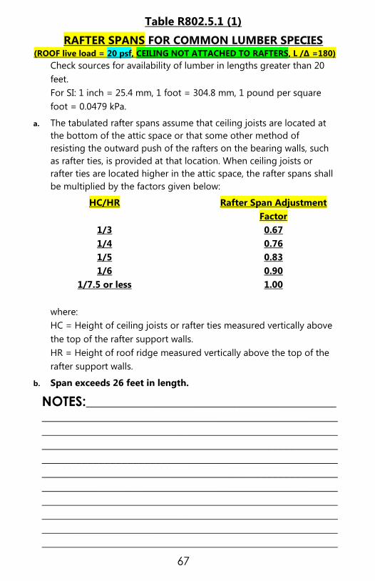
67
Table R802.5.1 (1)
RAFTER SPANS FOR COMMON LUMBER SPECIES (ROOF live load = 20 psf, CEILING NOT ATTACHED TO RAFTERS, L /∆ =180)
Check sources for availability of lumber in lengths greater than 20
feet.
For SI: 1 inch = 25.4 mm, 1 foot = 304.8 mm, 1 pound per square
foot = 0.0479 kPa.
a. The tabulated rafter spans assume that ceiling joists are located at
the bottom of the attic space or that some other method of
resisting the outward push of the rafters on the bearing walls, such
as rafter ties, is provided at that location. When ceiling joists or
rafter ties are located higher in the attic space, the rafter spans shall
be multiplied by the factors given below:
HC/HR Rafter Span Adjustment
Factor
1/3 0.67
1/4 0.76
1/5 0.83
1/6 0.90
1/7.5 or less 1.00
where:
HC = Height of ceiling joists or rafter ties measured vertically above
the top of the rafter support walls.
HR = Height of roof ridge measured vertically above the top of the
rafter support walls.
b. Span exceeds 26 feet in length.
NOTES:____________________________________________
____________________________________________________
____________________________________________________
____________________________________________________
____________________________________________________
____________________________________________________
____________________________________________________
____________________________________________________
____________________________________________________
____________________________________________________
____________________________________________________

68
Table R802.5.1 (2)
RAFTER SPANS FOR COMMON LUMBER SPECIES (ROOF Live Load = 20 psf, CEILING ATTACHED TO RAFTERS, L /∆ =240)
JOIST
SPACING
(inches)
SPECIES AND
GRADE
DEAD LOAD = 10 psf
2x4 2x6 2X 8 2x10 2x12
Maximum Rafter Spansa
(ft.- in.) (ft.- in.) (ft.- in.) (ft.- In.) (ft.- in.)
12
Southern pine SS 10-3 16-1 21-2 Note b Note b
Southern pine #1 9-10 15-6 20-5 Note b Note b
Southern pine #2 9-5 14-9 19-6 23-5 Note b
Southern pine #3 8-0 11-9 14-10 18-0 21-4
Spruce-pine-
fir
SS 9-8 15-2 19-11 25-5 Note b
Spruce-pine-
fir
#1 9-5 14-9 19-6 24-10 Note b
Spruce-pine-
fir
#2 9-5 14-9 19-6 24-10 Note b
Spruce-pine-
fir
#3 8-7 12-6 15-10 19-5 22-6
16
Southern pine SS 9-4 14-7 19-3 24-7 Note b
Southern pine #1 8-11 14-1 18-6 23-2 Note b
Southern pine #2 8-7 13-5 17-1 20-3 23-10
Southern pine #3 6-11 10-2 12-10 15-7 18-6
Spruce-pine-
fir
SS 8-9 13-9 18-1 23-1 Note b
Spruce-pine-
fir
#1 8-7 13-5 17-9 22-3 25-9
Spruce-pine-
fir
#2 8-7 13-5 17-9 22-3 25-9
Spruce-pine-
fir
#3 7-5 10-10 13-9 16-9 19-6
19.2
Southern pine SS 8-9 13-9 18-2 23-1 Note b
Southern pine #1 8-5 13-3 17-5 21-2 25-2
Southern pine #2 8-1 12-3 15-7 18-6 21-9
Southern pine #3 6-4 9-4 11-9 14-3 16-10
Spruce-pine-
fir
SS 8-3 12-11 17-1 21-9 Note b
Spruce-pine-
fir
#1 8-1 12-8 16-7 20-3 23-6
Spruce-pine-
fir
#2 8-1 12-8 16-7 20-3 23-6
Spruce-pine-
fir
#3 6-9 9-11 12-7 15-4 17-9
24
Southern pine SS 8-1 12-9 16-10 21-6 Note b
Southern pine #1 7-10 12-3 16-2 18-11 22-6
Southern pine #2 7-4 11-10 13-11 16-6 19-6
Southern pine #3 5-8 8-4 10-6 12-9 15-1
Spruce-pine-
fir
SS 7-8 12-0 15-10 20-2 24-7
Spruce-pine-
fir
#1 7-6 11-9 14-10 18-2 21-0
Spruce-pine-
fir
#2 7-6 11-9 14-10 18-2 21-0
Spruce-pine-
fir
#3 6-1 8-10 11-3 13-8 15-11
CONTINUED►

69
Table R802.5.1 (1)
RAFTER SPANS FOR COMMON LUMBER SPECIES (ROOF live load = 20 psf, CEILING NOT ATTACHED TO RAFTERS, L /∆ =240)
Check sources for availability of lumber in lengths greater than 20
feet.
For SI: 1 inch = 25.4 mm, 1 foot = 304.8 mm, 1 pound per square foot
= 0.0479 kPa.
a. The tabulated rafter spans assume that ceiling joists are located at the bottom of
the attic space or that some other method of resisting the outward push of the rafters
on the bearing walls, such as rafter ties, is provided at that location. When ceiling joists
or rafter ties are located higher in the attic space, the rafter spans shall be multiplied by
the factors given below:
HC/HR Rafter Span Adjustment
Factor
1/3 0.67
1/4 0.76
1/5 0.83
1/6 0.90
1/7.5 or less 1.00
where:
HC = Height of ceiling joists or rafter ties measured vertically above
the top of the rafter support walls.
HR = Height of roof ridge measured vertically above the top of the
rafter support walls.
b. Span exceeds 26 feet in length.
NOTES:____________________________________________
___________________________________________________
___________________________________________________
___________________________________________________
___________________________________________________
___________________________________________________
___________________________________________________
___________________________________________________
___________________________________________________
___________________________________________________
___________________________________________________
___________________________________________________

70
ROOF DOWN BRACING

71
R311.7.1Width. Stairways shall not be less than 36 inches (914 mm) in clear width at all points above
the permitted handrail height and below the required headroom height. Handrails shall not project more
than 4.5 inches (114 mm) on either side of the stairway and the minimum clear width of the stairway at
and below the handrail height, including treads and landings, shall not be less than 31-1/2 inches
(787mm) where a handrail is installed on one side and 27 inches (698 mm) where handrails are provided
on both sides. Exception: Spiral stairways shall be in accordance with Section R311.7.9.1.
R311.7.2 Headroom. The minimum + the sloped line adjoining the tread nosing or from the floor
surface of the landing or platform on that portion of the stairway.
Exception: Where the nosing of treads at the side of a flight extend under the edge of a floor
opening through which the stair passes, the floor opening shall be allowed to project horizontally
into the required headroom a maximum of 4-3/4 inches (121 mm).
R311.7.4.1 Riser height. The maximum riser height shall be 8-1/4 inches (210 mm). Measured vertically
between leading edges of the adjacent treads. Greatest riser height shall not exceed the smallest by
more than 3/8 inch (9.5mm). The top and bottom riser of interior stairs shall not exceed the smallest
riser within that stair run by more than 3/4 inch (19 mm). The height of the top and bottom riser of the
interior stairs shall be measured from the permanent finished surface (carpet excluded). Where the
bottom riser of an exterior stair adjoins an exterior walk, porch, driveway, patio, garage floor, or finish
grade, the height of the riser may be less than the height of the adjacent risers.
R311.7.4.2 Tread depth. Minimum tread depth shall be 9 inches (229 mm). Measured horizontally
between the vertical planes of the foremost projection of adjacent treads and at a right angle to the
tread’s leading edge. The greatest tread depth shall not exceed the smallest by more than 3/8 inch (9.5
mm). FOR WINDER TREADS REFER TO 2012 NCRC
R311.7.4.3 Profile. The radius of curvature at the nosing shall be no greater than 9/16 inch (14 mm). A
nosing not less than 3/4 inch but not more than 1-1/4 inches shall be provided on stairways with solid
risers. The greatest nosing projection shall not exceed the smallest nosing projection by more than 3/8
inch (9.5 mm) between two stories, including the nosing at the level of floors and landings. Beveling of
nosing shall not exceed 1/2 inch (12.7 mm). Risers shall be vertical or sloped under the tread above
from the underside of the nosing above at an angle not more than 30 degrees (0.51 rad) from the
vertical. Open risers are permitted, provided that the opening between treads does not permit the
passage of a 4-inch diameter (102 mm) sphere.
Exceptions:
1. A nosing is not required where the tread depth is a minimum of 11 inches (279 mm).
2. The opening between adjacent treads is not limited on stairs with a total rise of 30 inches (762
mm) or less.

72
Fireblocking, Draftstopping or Firestopping
People in the building industry believe these terms to be
interchangeable, and / or to be one and the same. However,
their use and purpose is very different.
Fireblock is a material whose main purpose is to be
used in concealed locations of combustible construction
to prevent fire from quickly spreading through these
spaces. Such a material will, as an inherent characteristic,
also slow the migration of smoke throughout the
building. Fireblock is typically applied in a horizontal
position to prevent the spread of fire (and thus air) in a
vertical manner.
Draftstop is a material whose main purpose is to be
used in concealed locations of combustible construction
to prevent the movement of slow air (oxygen) within open
or concealed areas Similar to firestopping, such a material
will, as an inherent characteristic, also slow the migration
of smoke throughout the building. Draftstopping is
typically applied in a vertical position to prevent the
spread of air in a horizontal manner (think
compartmentation), within concealed spaces such as
attics, crawlspaces, floor-ceiling and/or roof-ceiling
assemblies.
Firestop material is tested and approved for use in a
specific construction detail that reflects the installed
assembly, meant to protect rated penetrations by pipe,
wire, etc., to the same degree as the fire-rated wall, ceiling
or floor that is being penetrated.
What are acceptable fire blocking materials?
Types of material used as fireblock.
As per 2012 North Carolina Residential Code (NCRC),
Section R302.11 [R602.8] Fireblocking shall consist of:
a. Two-inch (51mm) nominal lumber.
b. Two thicknesses of 1-inch (25.4mm) nominal lumber with
broken lap joints.

73
c. One thickness of 23/32-inch (18.3 mm) wood structural
panels with joints backed by 23/32-inch (18.3 mm) wood
structural panels.
d. One thickness of 3/4-inch (19.1 mm) particleboard with
joints backed by 3/4-inch (19.1 mm) particleboard.
e. One-half inch (12.7 mm) gypsum board.
f. One-quarter inch (6.4 mm) cement-based millboard.
g. Batts or blankets of mineral wool or glass fiber or other
approved materials installed in such a manner as to be
securely retained in place.
R1003.19 Chimney Fire Blocking Wood fire blocking
materials or other combustible items cannot be used up
against chimneys regardless of the thickness.
Examples of where Fireblocking is used.
a. Separate open vertical spaces from open horizontal spaces,
(Figure 2)
b. The top and bottom of stairs, between stringers,

74
c. Within architectural trim, such as furred out wall finishes,
wainscoting, soffits, siding, DOI File # WP-060-11
Fireblocking Page 3 of 7 etc., (Figure 3).
d. Sleeper spaces, such as a raised floor,
e. Fill in spaces at floor and/or ceiling in fire-partitions
constructed of combustible materials,
f. Unrated membrane penetrations, such as when a hole for a
pipe or duct is cut out too large to be filled properly with
firestop material, the excess area can be filled with non-
combustible fireblock, and then the annular area around the
pipe/duct is filled with firestop material. (FIGURE 4)

75
T and F Ratings: What are T and F ratings?
T and F ratings are not applicable to Fireblock products; they
apply only to Firestop products, which are tested to resist the
passage of fire traditionally around penetrating items such as
pipes or wires. Their definitions can be found in the NC
Building Codes and are reprinted below.
A. F RATING. The time period that the through-penetration
firestop system limits the spread of fire through the
penetration when tested in accordance with ASTM E 814 or
UL 1479.
B. T RATING. The time period that the penetration firestop
system, including the penetrating item, limits the maximum
temperature rise to 325°F (163°C) above its initial
temperature through the penetration on the non-fire side
when tested in accordance with ASTM E 814 or UL 1479.
C. THROUGH-PENETRATION FIRESTOP SYSTEM. An
assemblage of specific materials or products that are
designed, tested and fire-resistance rated to resist for a
prescribed period of time the spread of fire through
penetrations. The F and T rating criteria for penetration
firestop systems shall be in accordance with ASTM E 814 or
UL 1479. See definitions of “F rating” and “T rating.”
NOTES:_________________________________________
_________________________________________________
_________________________________________________
_________________________________________________
_________________________________________________
_________________________________________________
_________________________________________________
_________________________________________________
_________________________________________________
_________________________________________________
_________________________________________________
_________________________________________________
_________________________________________________
_________________________________________________

76
FIRESTOPPING–COVE CEILING FIRESTOPPING–DROPPED CEILING
FIRESTOPPING-FURRED SOFFIT

77
Glazing 01/2015
R308.4 Hazardous locations. The following shall be
considered specific hazardous locations for the purposes of
glazing:
Glazing in all fixed and operable panels of swinging,
sliding and bi-fold doors.
EXCEPTIONS:
Glazed openings of a size through which a 3-inch
diameter (76 mm) sphere is unable to pass.
Decorative glazing.
Glazing in an individual fixed or operable panel
adjacent to a in the same plane as the door where the
nearest vertical edge is within 24-inches (610 mm) of
the door in a closed position and whose bottom edge
is less than 60 inches (1524 mm) above the floor or
walking surface.
EXCEPTIONS:
Decorative glazing.
When there is an intervening wall or other permanent
barrier between the door and the glazing.
Glazing in walls on the latch side of and perpendicular to
the plane of the door in a closed position. Deleted.
Glazing adjacent to a door where access through the
door is to a closet or storage area 3 feet (914 mm) or less
in depth.
Glazing that is adjacent to the fixed panel of patio doors.
Glazing in an individual fixed or operable panel that
meets all of the following conditions:
3.1 The exposed area of an individual pane is larger than 9
square feet (0.836 m2); and
3.2 The bottom edge of the glazing is less than 18 inches
(457 mm) above the floor; and

78
3.3 The top edge of the glazing is more than 36 inches
(914 mm) above the floor; and
3.4 One or more walking surfaces are within 36 inches (914
mm), measured horizontally and in a straight line, of the
glazing.
EXCEPTIONS:
Decorative glazing.
When a horizontal rail is installed on the accessible
side(s) of the glazing 34 to 38 inches (864 to 965)
above the walking surface. The rail shall be capable of
withstanding a horizontal load of 50 pounds per linear
foot (730 N/m) without contacting the glass and be a
minimum of 1-1/2 inches (38 mm) in cross sectional
height.
Outboard panes in insulating glass units and other
multiple glazed panels when the bottom edge of the
glass is 25 feet (7620 mm) or more above grade, a roof,
walking surfaces or other horizontal [within 45 degrees
(0.79 rad) of horizontal] surface adjacent to the glass
exterior.
All glazing in railings regardless of area or height
above a walking surface. Included are structural baluster
panels and nonstructural infill panels.
Glazing in enclosures for or walls facing hot tubs,
whirlpools, saunas, steam rooms, bathtubs and
showers, where the bottom exposed edge of the
glazing is less than 60 inches (1524 mm) measured
vertically above any standing or walking surface.
Exception: Glazing that is more than 60 inches (1524
mm), measured horizontally and in a straight line, from
the water’s edge of a hot tub, whirlpool or bathtub.
Glazing in walls and fences adjacent to indoor and
outdoor swimming pools, hot tubs and spas where the
bottom edge of the glazing is less than 60 inches (1524

79
mm) above a walking surface and within 60 inches
(1524 mm), measured horizontally and in a straight line,
of the water’s edge. This shall apply to single glazing
and all panes in multiple glazing.
Glazing adjacent to stairways, landings and ramps
within 36 inches (914 mm) horizontally of a walking
surface when the exposed surface of the glazing is less
than 60 inches (1524 mm) above the plane of the
adjacent walking surface.
Exceptions:
When a rail is installed on the accessible side(s) of
the glazing 34 to 38 inches (864 to 965 mm) above
the walking surface. The rail shall be capable of
withstanding a horizontal load of 50 pounds per
linear foot (730 N/m) without contacting the glass
and be a minimum of 1-1/2 inches (38 mm) in cross
sectional height.
The side of the stairway has a guardrail or handrail,
including balusters or in-fill panels, complying with
Sections R311.7.7 and R312 and the plane of the
glazing is more than 18 inches (457 mm) from the
railing; or
When a solid wall or panel extends from the plane
of the adjacent walking surface to 34 inches (863
mm) to 36 inches (914 mm) above the walking
surface and the construction at the top of that wall
or panel is capable of withstanding the same
horizontal load as a guard.
Glazing adjacent to stairways within 60 inches (1524
mm) horizontally of the bottom tread of a stairway in
any the direction of travel when the exposed surface of
the glazing is less than 60 inches (1524 mm) above the
nose of the tread.
Exceptions: Deleted.

80
TEMPERED GLAZING LOCATIONS

81
TEMPERED GLAZING LOCATIONS

82
SKYLIGHTS AND SLOPED GLAZING R308.6
R308.6.3 Screens, general. For fully tempered or heat-strengthened
glass, a retaining screen meeting the requirements of Section R308.6.7
shall be installed below the glass, except for fully tempered glass that
meets either condition listed in Section R308.6.5.
R308.6.4 Screens with multiple glazing. When the inboard pane is fully
tempered, heat-strengthened or wired glass, a retaining screen
meeting the requirements of Section R308.6.7 shall be installed below
the glass, except for either condition listed in Section R308.6.5. All
other panes in the multiple glazing may be of any type listed in
Section R308.6.2.
R308.6.5 Screens not required. Screens shall not be required when
fully tempered glass is used as single glazing or the inboard pane in
multiple glazing and either of the following conditions are met:
1. Glass area 16 square feet (1.49 m2) or less. Highest point of glass
not more than 12 feet (3658 mm) above a walking surface or other
accessible area, nominal glass thickness not more than 3/16 inch (4.8
mm), and (for multiple glazing only) the other pane or panes fully
tempered, laminated or wired glass.
2. Glass area greater than 16 square feet (1.49m2). Glass sloped 30
degrees (0.52 rad) or less from vertical, and highest point of glass not
more than 10 feet (3048 mm) above a walking surface or other
accessible area.

83
INSULATION
When is an insulation inspection required?
NCACP Section 107.1.6 Insulation inspections shall be made
after an approved building framing and rough-in inspection
and after the permanent roof covering is installed, with all
insulation and vapor retarders in place, but before any wall or
ceiling covering is applied.
What are the minimum R-values required for
walls, floors and ceilings?
Table N1102.1 Insulation shall be a minimum of R-13 in walls,
R-30 in ceilings and R-19 in floors. This is for zone 3 which is
Mecklenburg County.
What is the maximum slope a ceiling can be
before blown insulation cannot be used?
Typically, manufacturer's information discourages using blown
insulation for sloped ceilings. Insulation batts must be used.
Blown insulation can only be used for flat ceilings unless
specified for sloped ceilings by the manufacturer.
Are insulation markers necessary when using
blown insulation in the attic?
Section N1101.3.1 Yes, where blown-in or sprayed insulation
is applied in the roof-ceiling assembly, the installer shall
provide a certification of the initial installed thickness, settled
thickness, coverage area, and number of bags of insulating
material installed. Markers shall be provided for every 300
square feet of attic area, attached to the trusses, rafters, or
joists and indicate in 1-inch high numbers the installed
thickness of the insulation. The depth markers shall be
installed to the roof-ceiling assembly at time of wall insulation
and be viewable at the insulation inspection along with the
baffles.

84
FINAL INSPECTION
When is a final inspection required? NCACP Section 107.1.8 Final inspections shall be made for
each trade after completion of the work authorized under the
technical codes.
Is a separation required between the garage
and the living area? Section R302.6 Dwelling/garage fire separation. The garage
shall be separated as required by Table R302.6.(BELOW)
Openings in garage walls shall comply with Section R302.5.
This provision does not apply to garage walls that are
perpendicular to the adjacent dwelling unit wall.
R302.7 Under-stair protection. Enclosed accessible space
under stairs shall have walls, under-stair surface and any soffits
protected on the enclosed side with 1/2-inch (12.7 mm)
gypsum board.
TABLE R302.6
DWELLING / GARAGE SEPARATION
SEPERATION MATERIAL
From the residence and attics Not less than 1/2-inch gypsum board or
equivalent applied to the
garage side
From all habitable rooms
above the garage
Not less than 5/8-inch Type X gypsum
board or equivalent
Structure(s) supporting
floor/ceiling assemblies used for
separation
required by this section
Not less than 1/2-inch gypsum board
or equivalent
Garages located less than 3
feet from a dwelling unit on
the same lot
Not less than 1/2-inch gypsum board or
equivalent applied to the
interior side of exterior walls that are
within this area
For SI: 1 inch = 25.4 mm, 1 foot = 304.8 mm.
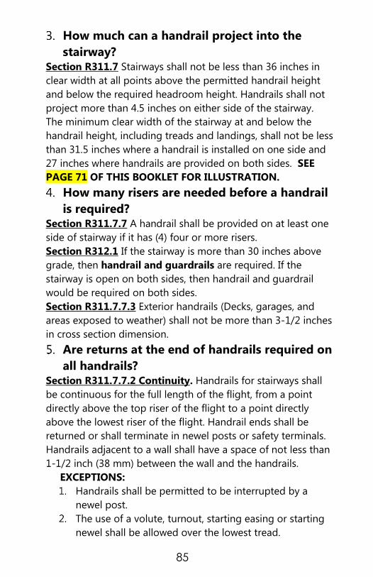
85
How much can a handrail project into the
stairway? Section R311.7 Stairways shall not be less than 36 inches in
clear width at all points above the permitted handrail height
and below the required headroom height. Handrails shall not
project more than 4.5 inches on either side of the stairway.
The minimum clear width of the stairway at and below the
handrail height, including treads and landings, shall not be less
than 31.5 inches where a handrail is installed on one side and
27 inches where handrails are provided on both sides. SEE
PAGE 71 OF THIS BOOKLET FOR ILLUSTRATION.
How many risers are needed before a handrail
is required? Section R311.7.7 A handrail shall be provided on at least one
side of stairway if it has (4) four or more risers.
Section R312.1 If the stairway is more than 30 inches above
grade, then handrail and guardrails are required. If the
stairway is open on both sides, then handrail and guardrail
would be required on both sides.
Section R311.7.7.3 Exterior handrails (Decks, garages, and
areas exposed to weather) shall not be more than 3-1/2 inches
in cross section dimension.
Are returns at the end of handrails required on
all handrails? Section R311.7.7.2 Continuity. Handrails for stairways shall
be continuous for the full length of the flight, from a point
directly above the top riser of the flight to a point directly
above the lowest riser of the flight. Handrail ends shall be
returned or shall terminate in newel posts or safety terminals.
Handrails adjacent to a wall shall have a space of not less than
1-1/2 inch (38 mm) between the wall and the handrails.
EXCEPTIONS:
Handrails shall be permitted to be interrupted by a
newel post.
The use of a volute, turnout, starting easing or starting
newel shall be allowed over the lowest tread.

86
Two or more separate rails shall be considered continuous if
the termination of the rails occurs within 6 inches (152 mm)
of each other. If transitioning between a wall-mounted
handrail and a guardrail/handrail, the wall-mounted rail must
return into the wall.
Are foundation drains allowed to terminate
outside the foundation wall underground? Section R405.2.3 The drainage system shall discharge into an
approved sewer system or to daylight.
Is regular gypsum board acceptable material
at shower and bath areas? Section R702.3.8 & R307.2 Gypsum board utilized as the
base or backer board for adhesive application of ceramic tile
or other nonabsorbent finish material shall conform to ASTM
C630 or C1178. Bathtub and shower floors and walls above
bathtubs with installed shower heads and in shower
compartments shall be finished with a nonabsorbent surface.
Such wall surfaces shall extend to a height of not less than 6
feet above the floor.
What is an acceptable location for the
insulation certificate? Section N1101.9 Certificate. A permanent certificate shall be
posted on or in the electrical distribution panel, in the attic
next to the attic insulation card, or inside a kitchen cabinet or
other approved location. The certificate shall not cover or
obstruct the visibility of the circuit directory label, service
disconnect label or other required labels. The builder, permit
holder, or registered design professional shall be responsible
for completing the certificate. The certificate shall list the
predominant R-values of insulation installed in or on
ceiling/roof, walls, foundation (slab, basement wall, crawlspace
wall and floor) and duct outside conditioned spaces; U-factors
for fenestration and the solar heat gain coefficient (SHGC) of
fenestration. Where there is more than one value for each
component, the certificate shall list the value covering the

87
largest area. The certificate shall indicate whether the building
air leakage was visually inspected as required in Section
N1102.4.2.1 or provide results of the air leakage testing
required in Section N1102.4.2.2 The certificate shall provide
results of duct leakage test required in Section N1102.4.2.2.
Appendix E-1 contains a sample certificate.
What are the more common items that
inspectors look at for the Final Inspection? Blown insulation is completed with a blown insulation
certificate card posted in the attic
Pull down stairs are installed per manufacturers'
requirements
Glass shower enclosures are complete and the required
tempered stamp present
Wall rails and banisters are properly installed
Garage area is properly fire stopped
All exterior penetrations are sealed
All exterior wood has at least a prime coat of paint
House numbers are installed
Final grading has positive drainage away from the
residence
NOTES:___________________________________________
___________________________________________________
___________________________________________________
___________________________________________________
___________________________________________________
___________________________________________________
___________________________________________________
___________________________________________________
___________________________________________________
___________________________________________________
___________________________________________________
___________________________________________________
___________________________________________________
___________________________________________________
___________________________________________________

88
EXTERIOR WOOD DECKS
A deck is an exposed exterior wood floor
structure which may be attached to the
structure or freestanding. Roofed porches
(open or screened-in) may be constructed
using these provisions.
Support posts shall be supported by a footing.
FOOTING CHART
TABLE AM102.1 FOOTING TABLE, a, b, c
SIZE (inches) TRIBUTARY
AREA
(square
feet)
THICKNESS
(inches)
Precast
Footings
A X A
Cast-in-
Place
Footings
B X C
Precast
Cast-
in-
Place
8 X 16 8 X 16 36 4 6
12 X 12 12 X 12 40 4 6
16 X 16 16 X 16 70 8 8
___ 16 X 24 100 ___ 8
___ 24 X 24 150 ___ 8
For SI: 1 inch = 25.4 mm, 1 square foot = 0.0929m2.
a. Footing values are based on single floor and roof loads
b. Support post must rest in center 1/3 of footer
c. Top of footer shall be level for full bearing support of post
NOTES:___________________________________________
___________________________________________________
___________________________________________________
___________________________________________________
___________________________________________________
___________________________________________________
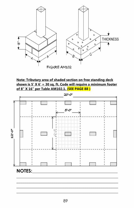
89
Note: Tributary area of shaded section on free standing deck
shown is 5’ X 6’ = 30 sq. ft. Code will require a minimum footer
of 8” X 16” per Table AM102.1. (SEE PAGE 88 )
NOTES:__________________________________________
__________________________________________________
__________________________________________________
__________________________________________________
__________________________________________________
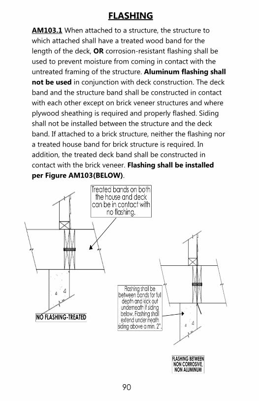
90
FLASHING
AM103.1 When attached to a structure, the structure to
which attached shall have a treated wood band for the
length of the deck, OR corrosion-resistant flashing shall be
used to prevent moisture from coming in contact with the
untreated framing of the structure. Aluminum flashing shall
not be used in conjunction with deck construction. The deck
band and the structure band shall be constructed in contact
with each other except on brick veneer structures and where
plywood sheathing is required and properly flashed. Siding
shall not be installed between the structure and the deck
band. If attached to a brick structure, neither the flashing nor
a treated house band for brick structure is required. In
addition, the treated deck band shall be constructed in
contact with the brick veneer. Flashing shall be installed
per Figure AM103(BELOW).

91
DECK ATTACHMENT
AM104.1 When the deck is supported at the structure by
attaching the deck to the structure, the following attachment
schedules shall apply for attaching the deck band to the
structure.
AM 104.1.1
All Structures Except Brick Veneer
Method Fasteners
8’ Max
Joist Span a
16’ Max
Joist Span a
1
5/8” Hot Dipped Galv.
Bolts with nut and
washer b and
12d Common Hot
Dipped Galv. Nails c
1 @ 3’-6”
O.C.
and
2 @ 8” O.C.
1 @ 1’-8”
O.C.
and
3 @ 6” O.C.
OR
2 Self-Drilling Screw
Fastener d 12” O.C.
staggered
6” O.C.
staggered
AM 104.1.2
Brick Veneer Structures
5/8” Hot Dipped Galv. Bolts with
Nut and Washer b
1@ 2’-4”
O.C.
1@ 1’-4”
O.C.
a. Attachment interpolation between 8 foot & 16 foot joists span are allowed,
b. Minimum edge distance for bolts is 2-1/2 inches,
c. Nails must penetrate supporting structure band a minimum of 1-1/2
inches
d. Self-drilling fastener shall be an approved screw having a minimum shank
diameter of 0.195” and a length long enough to penetrate through the
supporting structure band. The structure band shall have a minimum depth
of 1-1/8”. Screw shall have an evaluated allowable shear load for Southern
Pine to Southern Pine lumber of 250 pounds and shall have a corrosion
resistant finish equivalent to hot dipped galvanized. Minimum edge
distance for screws is 1-7/16”. A minimum of 1/2” thick wood structural
panel if permitted to be located between the deck and the structural band.
92
MASONRY LEDGE SUPPORT
AM104.1.3 If the deck band Is supported by a minimum of
1/2-inch masonry ledge along the foundation wall, 5/8 inch
hot dipped galvanized bolts with washers spaced at 48 inches
o.c. may be used for support.
OTHER MEANS OF SUPPORT
AM104.1.4 Joist hangers or other means of attachment may
be connected to the house band and shall be properly flashed.
GIRDER SUPPORT AND SPANS
AM105.1 Girders shall bear directly on support post with post
attached at top to prevent lateral displacement or be
connected to the sides of the post with two 5/8 inch hot
dipped galvanized bolts with nut and washer. Girder support
may be installed per Figure AM105 for top mount; Figure
AM105.1 for side mount and Figure AM105.2 for split girder
detail. Pages 93-94.
Girders may also be cantilevered off ends of support post no
more than 1 joist spacing or 16 inches, whichever is greater
per Figure AM105.3.
JOIST SPANS AND CANTILEVERS
AM106.1 Joist spans shall be based upon Table R502.3.1(2)
(ON PAGE 61 OF THIS BOOKLET) with 40lbs per sq ft live
load and 10 lbs per sq ft dead load. Floor Joists Supporting
Light-Frame Exterior Bearing Wall and Roof for exterior
decks may be cantilevered per Table R502.3.3 (1) (ON PAGE
62 OF THIS BOOKLET) NOTE: This Table is based on the use
of #1 and better SYP Lumber, #2 Grade Douglas fir-larch,
Hem fir and Spruce- pine-fir under the Ground Snow Load of
<20 psf. There are no provisions in the NCRC that allows
the use of #2 SYP for cantilever design.
CAUTION: The current methods of chemically preserving lumber
are much more corrosive to hardware and fasteners than those
used in the past. The use of APPROVED corrosion resistant
hardware, structural connectors and fasteners is required.
(Example; ACQ treated lumber would require the use of ACQ
approved or triple galvanized hardware.)

93
FIGURE AM 105
FIGURE AM 105.1

94
AM108.1
Maximum Height of Deck Support Posts are as follows:
POST SIZE a MAXIMUM POST HEIGHT b, c
4 x 4 8' - 0"
6 x 6 20' - 0'
••• Over 20' - 0'
a. This table is based on No. 2 treated Southern Pine posts.
b. From top of footing to bottom of girder.
c. Decks with post heights exceeding these requirements shall be
designed by a registered design professional.
Maximum tributary Area is based on 128 total square feet which
may be located at different levels.
NOTES:__________________________________________
__________________________________________________
__________________________________________________
__________________________________________________
__________________________________________________
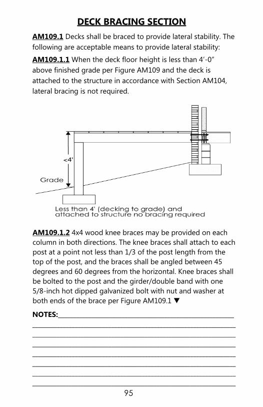
95
DECK BRACING SECTION
AM109.1 Decks shall be braced to provide lateral stability. The
following are acceptable means to provide lateral stability:
AM109.1.1 When the deck floor height is less than 4’-0”
above finished grade per Figure AM109 and the deck is
attached to the structure in accordance with Section AM104,
lateral bracing is not required.
AM109.1.2 4x4 wood knee braces may be provided on each
column in both directions. The knee braces shall attach to each
post at a point not less than 1/3 of the post length from the
top of the post, and the braces shall be angled between 45
degrees and 60 degrees from the horizontal. Knee braces shall
be bolted to the post and the girder/double band with one
5/8-inch hot dipped galvanized bolt with nut and washer at
both ends of the brace per Figure AM109.1 ▼
NOTES:__________________________________________________________
___________________________________________________________________
___________________________________________________________________
___________________________________________________________________
___________________________________________________________________
___________________________________________________________________
___________________________________________________________________
___________________________________________________________________

96
AM109.1.3 For free standing decks without knee braces or
diagonal bracing, lateral stability may be provided by
embedding the post in accordance with Figure AM109.2 and
the following: ▼
POST
SIZE
MAXIMUM
TRIBUTARY
AREA
MAXIMUM
POST
HEIGHT
EMBEDMEN
T DEPTH
CONCRETE
DIAMETER
4 x 4 48 SF 4' - 0' 2’- 6” 1' - 0”
6 x 6 120 SF 6' - 0" 3' - 6” 1' - 8”
NOTES:__________________________________________________________
___________________________________________________________________
___________________________________________________________________
___________________________________________________________________
___________________________________________________________________
___________________________________________________________________
___________________________________________________________________
___________________________________________________________________
___________________________________________________________________
___________________________________________________________________

97
AM109.1.4 2 x 6 diagonal vertical cross bracing may be
provided in two perpendicular directions for freestanding
decks or parallel to the structure at the exterior column line for
attached decks. The 2 x 6's shall be attached to the posts with
one 5/8-inch hot dipped galvanized bolt with nut and washer
at each end of each bracing member PER FIGURE AM109.3 ▼

98
FLOOR DECKING
AM107.1 A Floor decking shall be No. 2 grade treated
Southern Pine or equivalent. The minimum floor decking
thickness shall be as follows:
STAIRS
AM110 STAIRS SHALL BE CONSTRUCTED PER FIGURE
BELOW.
STRINGER SPANS SHALL BE NO GREATER THAN 7 FOOT SPAN
BETWEEN SUPPORTS. SPACING BETWEEN STRINGERS SHALL
BE BASED UPON DECKING MATERIAL USED PER FLOOR
DECKING MATERIAL USED PER AM107.1 ABOVE. EACH
STRINGER SHALL HAVE A MINIMUM 3 1/2 INCHES BETWEEN
STEP CUT AND THE BACK OF THE STRINGER. IF USED,
SUSPENDED HEADERS SHALL BE ATTACHED WITH 3/8 INCH
GALVANIZED BOLTS WITH NUTS AND WASHERS TO
SECURELY SUPPORT STRINGERS AT THE TOP. ▼
JOIST SPACING DECKING (NOMINAL)
12” – O.C. 1" S4S
16" - O.C. 1' T & G
24" - O.C. 1 1/4” S4S
32 " – O.C. 2" S4S
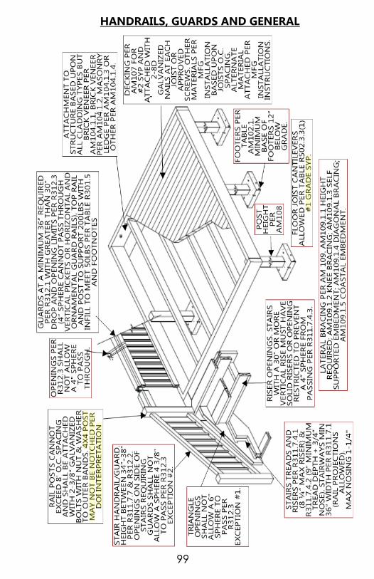
99
HANDRAILS, GUARDS AND GENERAL
100
SWIMMING POOLS, SPAS & HOT TUBS
What are the requirements for swimming pool,
spa and hot tub barriers or fences? A. Appendix G Section 105 An outdoor swimming pool,
including an in-ground, above-ground or on-ground pool,
hot tub or spa shall be surrounded by a barrier which shall
comply with the following:
The top of the barrier shall be at least 48 inches
(1219mm) above grade measured on the side of the
barrier which faces away from the swimming pool. Where
the top of the pool structure is above grade, such as an
above-ground pool, the barrier may be at ground level,
such as the pool structure, or mounted on top of the
pool structure. The maximum vertical clearance between
grade and the bottom of the barrier shall be 2 inches (51
mm) measured on the side of the barrier which faces
away from the swimming pool. Where the barrier is
mounted on top of the pool structure, the maximum
vertical clearance between the top of the pool structure
and the bottom of the barrier shall be 4 inches (102 mm).
Openings in the barrier shall not allow passage of a 4-
inch-diameter (102 mm) sphere.
Solid barriers which do not have openings, such as a
masonry or stone wall, shall not contain indentations or
protrusions except for normal construction tolerances
and tooled masonry joints.
Where the barrier is composed of horizontal and vertical
members and the distance between the tops of the
horizontal members is less than 45 inches (1143 mm), the
horizontal members shall be located on the swimming
pool side of the fence. Spacing between vertical
members shall not exceed 1-3/4 inches (44 mm) in width.
Where the barrier is composed of horizontal and vertical
members and the distance between the tops of the
horizontal members is 45 inches (1143 mm) or more,
spacing between vertical members shall not exceed 4
inches (102mm). Where there are decorative cutouts

101
within vertical members, spacing within the cutouts shall
not exceed 1-3/4 inches (44 mm) in width.
Maximum mesh size for chain link fences shall be a 2-
1/4-inch (57 mm) square unless the fence has slats
fastened at the top or the bottom which reduce the
openings to not more than 1-3/4 inches (44 mm).
Where the barrier is composed of diagonal members,
such as a lattice fence, the maximum opening formed by
the diagonal members shall not be more than 1-3/4
inches (44 mm).
Access gates shall comply with the requirements of
Section AG105.2, Items 1 through 7, and shall be
equipped to accommodate a locking device. Pedestrian
access gates shall open outward away from the pool and
shall be self-closing and have a self-latching device.
Gates other than pedestrian access gates shall have a
self-latching device. Where the release mechanism of the
self-latching device is located less than 54 inches (1372
mm) from the bottom of the gate, the release mechanism
and openings shall comply with the following:
8.1. The release mechanism shall be located on the pool
side of the gate at least 3 inches (76mm) below the top
of the gate; AND
8.2. The gate and barrier shall have no opening larger
than 1/2 inch (12.7 mm) within 18 inches (457mm) of the
release mechanism.
Where a wall of a dwelling serves as part of the barrier,
ONE of the following conditions shall be met:
9.1. The pool shall be equipped with a powered safety cover
in compliance with ASTM F 1346; OR
9.2. Doors with direct access to the pool through that wall
shall be equipped with an alarm which produces an audible
warning when the door and/or its screen, if present, are
opened. The alarm shall be listed and labeled in accordance
with UL 2017. The deactivation switch(es) shall be located at
least 54 inches (1372 mm) above the threshold of the door;
OR

102
9.3. Other means of protection, such as self-closing doors
with self-latching devices, which are approved by the
governing body, shall be acceptable as long as the degree of
protection afforded is not less than the protection afforded
by Item 9.1 or 9.2 described above.
What are the requirements for above ground
swimming pools? Where an above-ground pool structure is used as a barrier or
where the barrier is mounted on top of the pool structure, and
the means of access is a ladder or steps:
A. The ladder or steps shall be capable of being secured,
locked or removed to prevent access; OR
B. The ladder or steps shall be surrounded by a barrier
which meets the requirements of Section AG105.2, Items
1 through 9. When the ladder or steps are secured,
locked or removed, any opening created shall not allow
the passage of a 4-inch-diameter (102 mm) sphere.
What are the requirements for spas and hot
tubs? Spas or hot tubs with a safety cover which complies with ASTM
F 1346, as listed in Section AG107, shall be exempt from the
provisions of this appendix.
What are the requirements for entrapment
protection for swimming pool and spa suction
outlets? AG106.1 Suction outlets shall be designed and installed in
accordance with ANSI/APSP-7.
NOTES:__________________________________________________________
___________________________________________________________________
___________________________________________________________________
___________________________________________________________________
___________________________________________________________________
___________________________________________________________________
___________________________________________________________________

103
MINIMUM FENCE REQUIREMENTS

104
Residential Sales Center Requirements Needs to meet the Accessibly Code A117.1.
Need to check that heated space is correct if using garage as
sales office. Do not need to stripe if parking space in
driveway.
Permit requirements (2 ways to permit):
A. Structure can be permitted all at one time at initial
permit stage to show total heated square footage of
house and garage area (no garage indicated on
application form).
B. If structure is permitted as having a garage, then a
second permit will be required to change that garage
area to a sales center (Supplemental permit). This
would mean that there would be 2 frame, 2 insulation
and 2 final inspections on this site. Inspection request
on both permits would need to be scheduled by the
contractor.
If the garage area is converted back from sales center to a
garage, then a new permit is required for that conversion
to check structure and verify removal of HVAC registers.
Conversion permit back to garage will be the
responsibility of the owner (either the builder at that time
or the home owner if sold and converted).
Other Requirements:
Parking on the site where the Sales Center is located.
Van Accessible access parking space with signage (8'
parking, 8' access aisle) per section 4.4.1 ANSI A117.1.
Space and access isle should be paved and must be
marked per section 4.2.3 ANSI A117.1 .
Access route 4' wide, ramps and any handrails if needed
per Chapter 5 of Accessibility Code Entrance door and
all interior doors inside the sales office area must be 3/0
with lever handles and entrance door must have low
profile threshold, door requirements listed in Chapter 7
of NC Accessibility Code.

105
One (1) accessible bathroom facility either inside the office
space or home with accessible route or an accessible
porta-jon can be provided for the duration of the sales
center usage. Location of the porta-jon and its access
should be discussed with inspector.
If you have other concerns, you can refer to the NCDOI
web site. The following is a link to Model Home Access
Questions from NCDOI.
http://www.ncdoi.com/OSFM/Engineering_and_Codes/
Documents/Accessibility/020808.pdf
Any concerns about meeting these requirements at a
specific jobsite should be discussed with an area field
inspector prior to installation.
***Residential Sales Center Requirements from Mecklenburg
County Consistency Meeting 05/06/2015.
NOTES:__________________________________________________________
___________________________________________________________________
___________________________________________________________________
___________________________________________________________________
___________________________________________________________________
___________________________________________________________________
___________________________________________________________________
___________________________________________________________________
___________________________________________________________________
___________________________________________________________________
___________________________________________________________________
___________________________________________________________________
___________________________________________________________________
___________________________________________________________________
___________________________________________________________________
___________________________________________________________________
___________________________________________________________________
___________________________________________________________________
___________________________________________________________________
___________________________________________________________________

106
PLAN REVIEW FOR CHILD CARE IN A RESIDENCE (MAXIMUM 12 FULL TIME CHILDREN, PRIMARY CARE
GIVER MUST LIVE IN RESIDENCE)
PURPOSE: To ensure child care facilities in a residence meet:
1. N.C. State Building Code.
2. N.C. State Fire Code and local Ordinances
3. N.C. Dept. of Environment and Natural Resources, Division
of Environmental Health Regulations enforced by Mecklenburg
County Health Dept.
4. N.C. Dept. of Health and Human Services, Division of Health
Service Regulation (DHSR formerly DFS) and the Division of
Child Development Regulations.
***PHONE NUMBERS FOR THESE AGENCYS ARE ON PAGE 106.
Please follow these simple guidelines outlined below to get
you started. Full Plan Review Requirements will follow.
1. Zoning: It is critical to know what your zoning category is
before opening any type of business. To determine zoning
requirements and status in Mecklenburg County call 311 or if
outside of our area call 704-336-7600. For the Surrounding
towns, Cornelius, Davidson, Huntersville, Matthews, Mint Hill,
and Pineville please call their office directly.
2. For Adult Day Cares, contact the Department of Health and
Human Services, Division of Aging and Adult Services at 919-
855-3400. For Child Care Facilities contact Michele, NC Division
of Child Development at 704-594-0151.
[email protected] Applicants will need a
confirmation letter from Licensing stating proposed age and
number of kids or adults being served to pre-qualify for the
respective facility and license. A copy of this letter must
accompany the building permit application at submittal.
3. Applicants should contact Residential Plan Review services
at 980-314-CODE (2633) to schedule a preliminary
appointment to discuss the North Carolina Building Code
requirements and other guidelines set forth by the Department
of Health and Human Services or other licensing entity.
At the time of meeting, documentation will be required to
validate you have approval from the County Zoning
Department and have been pre-qualified from the Department

107
of Health and Human Services (Adult) to help facilitate your
code compliance process.
ADDITIONAL INFORMATION:
Please research the North Carolina General Statutes
concerning Adult and Child Day Cares, NC GS 131D-6(b) and
NC GS 110 respectively.
PLAN SUBMITTAL REQUIREMENTS (Know beforehand the
service/license applied for.):
Complete Plans consisting of 2 pages drawn to scale,
minimum size 11” x 17” are to be submitted electronically
(PDF) via the contractors account at www.meckpermit.com
along with permitting, zoning plot plan documents, Health
Department Application and NC State Licensing Letter.
A. PAGE 1 of set will be a SITE plan showing:
1. Property lines of lot.
2. Home location on lot.
3. Porches, decks, ramps.
4. Exit doors
5. Driveways, sidewalks.
6. Complete property address, owner name and
contact information.
B. PAGE 2 of the set shall a legible floor plan drawn to scale
indicating:
1. Room location/name (Day care area, bedroom, bath,
kitchen, etc.) and area sq. ft. tabulation.
2. Identify rooms where children will be kept. (children can
only be on same floor level as the exit.)
3. Two remote exits are required directly to the exterior, one
with 36-inch side hinged door and Accessibility Standard
landing and ramp. Secondary exit minimum 32” clear
opening. (Exception: One 36-inch-wide side hinged door
providing direct egress to outdoors with above
landing/ramp is allowed providing daycare area is confined
to the one area of exit. Day Care occupancy limited to ten.).
(NCBC 426 ADULT AND CHILD DAY CARE, SECTION 1001.1
ADMINISTRATION-General and 1015 EXIT AND EXIT
ACCESS DOORWAYS.)

108
4. Door Hardware: Lever handles are required; double
cylinder deadbolt latches are prohibited. (NCBC 1008.1.9
Door operations & NCRC R311.2 Egress door) (All doors.).
5. Detailed layout of Kitchen showing location of cabinets, 2
compartment kitchen sink and proposed location of
separate hand washing sink. (must be approved by Health
Department before installation) Appliance location. (Label
appliances: Ref., Range, Dishwasher, etc.)
6. Detailed layout of Bathroom showing location of sinks,
toilet, tubs, showers, cabinets, etc.
7. Show location of Fire Extinguisher and 1 manual pull Fire
Alarm. (call Fire Department for Specific Requirements)
8. Wall and ceiling coverings are to be of non-combustible
materials (plaster or gypsum wallboard) (NCBC 426.1.3
Walls and ceilings - Adult and Child Day Care).
9. Smoke alarms in the residence ARE REQUIRED to be
updated, interconnected and hardwired if the home has an
accessible attic/crawlspace that would allow this without
removal of interior finishes. (NCRC 2012 R314 Smoke
Alarms)
10. Fire Extinguishers: At least one 2-A:10-BC shall be provided
per floor with a maximum of 40 feet travel distance to the
extinguisher.
11. Adult Day Care: Check with the State Adult Day Care
consultants as State requirements exceed the minimum
Code requirements set forth in the NC Building & North
Carolina Residential Codes.
THE PROCESS:
1. Verify City/County Zoning requirements can be met and
acquire Zoning Letter of Intent.
2. Provide verification from the Division of Health Service
Regulation (DHSR formerly DFS) or State Child Care consultant
stating the type of license that is being applied for. Verification
is required to have the following information: Address, Type of
Licensing applying for, any limitations to include number of
children and age group of the children.

109
3. Provide complete plans and the Mecklenburg County Health
Department. application for in-home day care, submitted
electronically with permit and zoning application, minimum
plan size 11” X 17”. A $300 (non-refundable) Plan Review fee
will be charged once plans are accepted for review.
4. The Building permit application shall have all Building and/or
other Trades permits listed as required. Once approved,
stamped plans will be available online to be printed out and
utilized for inspections and are required to be on site at the
day care location for Building Inspector, Health Department
Official and Childcare Consultant use.
5. Permitting might require placement of an account with a
$2,000.00 cash bond or surety bond with Mecklenburg County
before permit issuance if the Plan Review and Primary Building
permit is submitted under the Day Care name as contractor.
**For projects that involve an addition to a structure or
renovations call Residential Plan Review for additional
requirements at (980) 314-CODE (2633).
Child Care Regulatory Agencies 10/2016
Mecklenburg County
Residential Services
Plan Review Department
700 North Tryon Street
Charlotte, N.C. 28202
Phone: (980) 314-CODE (2633)
Fax: 1-866-851-3553
Mecklenburg County Health
Department
700 North Tryon Street
Charlotte, N.C. 28202
Phone: (704) 336-5100
Fax: (704) 336-5306
N.C. Department of Health
and Human Services
Division of Child Development
& Early Education
Phone: (919) 859-0829
Fax: (919) 715-1012
Mecklenburg County Zoning
Department
700 North Tryon Street
Charlotte, N.C. 28202
Phone: 311 or (704) 336-7600
Fax: (704) 353-0196
Mecklenburg County Fire Marshal
(Outside City of Charlotte)
Phone: (980)-314-3070
City of Charlotte Fire Prevention
(Inside City of Charlotte)
Phone: (704) 336-2101
Fax: (704) 336-5190

110
NOTES:_____________________________________________
____________________________________________________
____________________________________________________
____________________________________________________
____________________________________________________
____________________________________________________
____________________________________________________
____________________________________________________
____________________________________________________
____________________________________________________
____________________________________________________
____________________________________________________
____________________________________________________
____________________________________________________
____________________________________________________
____________________________________________________
____________________________________________________
____________________________________________________
____________________________________________________
____________________________________________________
____________________________________________________
____________________________________________________
____________________________________________________
____________________________________________________
____________________________________________________
____________________________________________________
____________________________________________________
____________________________________________________
____________________________________________________
____________________________________________________
____________________________________________________
____________________________________________________
____________________________________________________
____________________________________________________
____________________________________________________
____________________________________________________
____________________________________________________


