Restricted Earth Fault Relay 5B3
The policy of Easun Reyrolle is one of continuous improvement and development. The company therefore reserves the right to supply equipment,
which may differ slightly from that described and illustrated in this publication.
Description
The relay uses a type B61 attracted armature element energized
via a low pass filter circuit and a full wave rectifier. The relay has
a pre-set setting of 15V. Other resistors are introduced into the
circuit to provide the voltage setting range up to 270V in
increments of 5V using heavy duty DIL switches.
Included within the relays, are the essential non-linear resistors
to limit the peak voltage output from saturated C.T.s, these
resistors protect the C.T. insulation and secondary wiring.
Current Transformer RequirementsExperience has shown that most protective C.T.s are suitable for
use with the high impedance relays and where the C.T.s are
specially designed for this protection, their overall size may be
smaller than that required for an alternative current balance
protection. The basic requirements are:
a) All C.T.s should have identical turns ratios, if possible.
b) The knee point voltage of each C.T. should be at least 2xVs.
The knee point voltage is expressed as the voltage applied to
the secondary circuit with the primary open circuit which when
increased by 10% causes the magnetizing current to increase
by 50%.
c) C.T.s should be of the low leakage reactance type.
Most modern C.T.s are of this type and there is no difficulty in
meeting this requirement. A low leakage reactance C.T. has a
jointless ring type core, the secondary winding evenly
distributed along the whole length of the magnetic circuit and
the primary conductor passes through the approximate centre
of the core.
Applications
Type 5B3 electromagnetic relay is ideal for restricted earth fault
protection of transformer windings or phase and earth fault
protection of reactors and the stator windings of large machines.
This relay may also be used for high impedance busbar protection.
High impedance schemes have the advantages over low
impedance schemes that, a more sensitive setting can be obtained
without any loss of stability and the primary fault setting
calculation is simpler. Current operated schemes are more
susceptible to mal-operations from through faults, unless greater
care is taken with the selection of the current transformer.
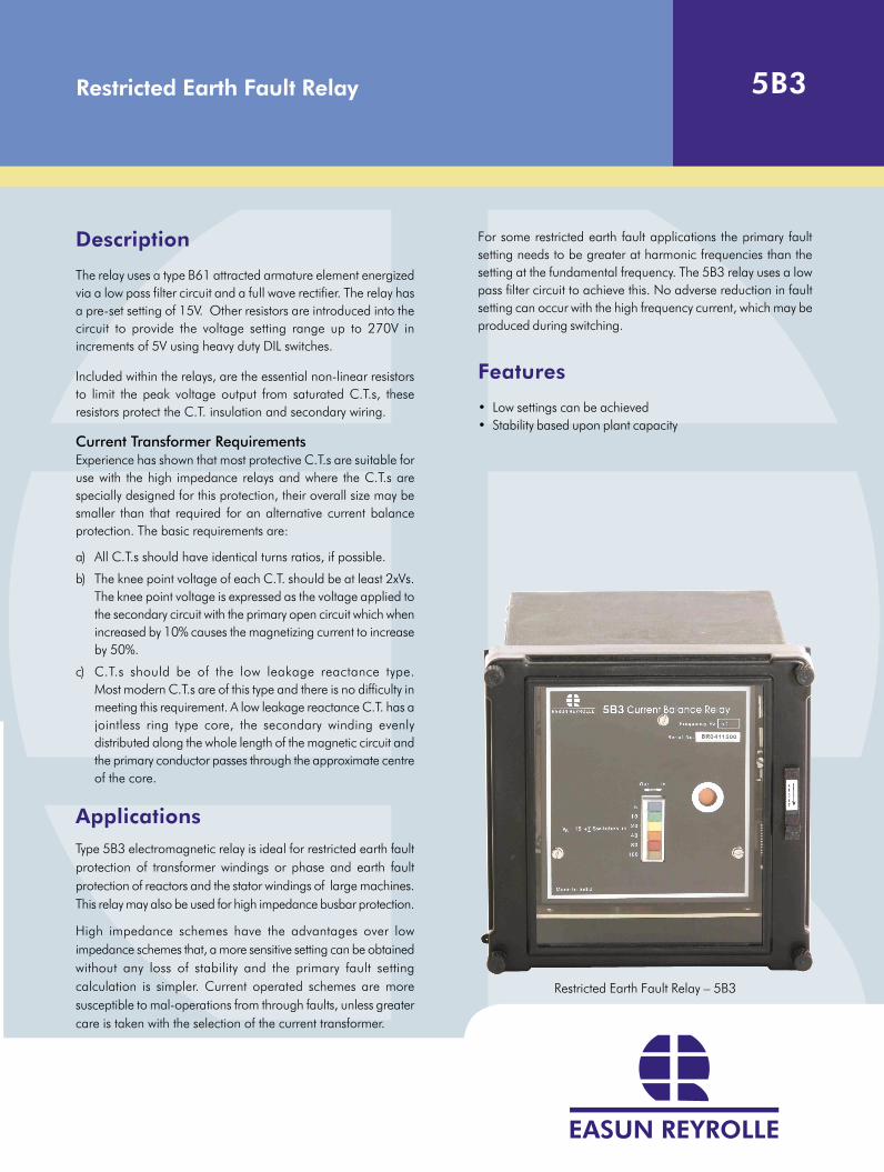
Restricted Earth Fault Relay – 5B3
For some restricted earth fault applications the primary fault
setting needs to be greater at harmonic frequencies than the
setting at the fundamental frequency. The 5B3 relay uses a low
pass filter circuit to achieve this. No adverse reduction in fault
setting can occur with the high frequency current, which may be
produced during switching.
Features
• Low settings can be achieved
• Stability based upon plant capacity
Fault Setting
It should, however, be noted that because the operating voltage
of the relay circuit is relatively high, the excitation currents of the
C.T.’s in parallel with the relay may comprise a large proportion
of the fault setting.
Primary fault setting = N (l0 + l
1 + l
2 + l
3)
Where:
I0
= Relay operating current
I1 etc = Excitation current of each C.T at the relay setting voltage
N = C.T. turns ratio
Ordering Information
• For Single Element-2/3V
• For Three Element -2V
Qualification
ISO 9001-2000
FACT
/5B3
/08-
07/R
EV 1
®Easu
n R
eyro
lle-2
007 -
Easu
n R
eyro
lle,
the
Easu
n R
eyro
lle l
ogo a
nd a
ny
alte
rnativ
e ve
rsio
n t
her
eof
are
reg
iste
red t
rade
mark
s and s
ervi
ce m
ark
s of
Easu
n R
eyro
lle
Sales OfficesBangaloreEasun Reyrolle Ltd.#17/3 Arakere, Bannerghatta Road,Bangalore - 560 076, India.Tel: +91 80 26581023/3268Fax: +91 80 26580642Email: [email protected]
BhopalEasun Reyrolle Ltd.H.No.16, Essarjee HomesNear Gopal Nagar, Kalan RoadPiplani, Bhopal - 462 021, India.Telefax: +91 755 2684221Email: [email protected]
ChennaiEasun Reyrolle Ltd.6th Floor, Temple Tower, 672,Anna Salai, NandanamChennai - 600 035, India.Tel: +91 44 24346425/24347608Fax: +91 44 24346435Email: [email protected]
DelhiEasun Reyrolle Ltd.29/12, Ground Floor, East Patel NagarNew Delhi - 110 008, India.Tel: +91 11 25747321/25747322Fax: +91 11 25747320Email: [email protected]
KolkataEasun Reyrolle Ltd.4, Dr.Sundari Mohan Avenue, 5th FloorFlat No.18, Kolkata - 700 014, India.Tel: +91 33 22848320Fax: +91 33 22848326Email: [email protected]
MumbaiEasun Reyrolle Ltd.23, Kasturi Building, Jamshedji Tata RoadMumbai - 400 020, India.Tel: +91 22 22022270/22855415Fax: +91 22 22825703Email: [email protected]
SecunderabadEasun Reyrolle Ltd.#2, 1st Floor, Paradise ChambersOpp Hotel Ambassador1-7-196 Prender Ghast RoadSecunderabad - 500 003, India.Telefax: +91 40 27817847Email: [email protected]
CORPORATE OFFICEEasun Reyrolle Limited.,98 Sipcot Industrial ComplexHosur 635 126, India.Tel: +91 4344 401600/01/02Fax: +91 4344 276397
TURNKEY PROJECTSBUSINESS/AMR BUSINESS#389, “Rasukumaki”, HulimavuBegur Hobli, Bannerghatta RoadBangalore - 560 076, India.Tel: +91 80 40477200/ 201Fax: +91 80 40477202Email: [email protected]
HOSUR WORKS#98, Sipcot Industrial ComplexHosur - 635 126, India.Tel: +91 4344 401600/01/02Fax: +91 4344 276397
CENTRAL MARKETING &EXPORTS BUSINESS#17/3 ArakereBannerghatta RoadBangalore - 560 076, India.Tel: +91 80 26581023/3268Fax: +91 80 26580642Email: [email protected]
BANGALORE WORKS#17/3 Arakere, Bannerghatta RoadBangalore - 560 076, India.Tel: +91 80 26581023/3268Fax: +91 80 26580642Email: [email protected]
AUTOMATION BUSINESS#389, “Rasukumaki”, HulimavuBegur Hobli, Bannerghatta RoadBangalore - 560 076, India.Tel: +91 80 40477200/ 201Fax: +91 80 40477202Email: [email protected]
Corporate OfficeEasun Reyrolle Limited. 98 Sipcot Industrial Complex,
Hosur 635 126 India.Tel: +91 4344 401600/01/02
Fax: +91 4344 276397www.easunreyrolle.com
Technical Information
Frequency fn. 50Hz.
Settings
Current Is : Fixed at 20mA.
Voltage Vs : 15V to 270V in steps of 5V
Thermal withstand Continuous 1.25 x Vs
Burden Vs x 20mA. (approx)
Operating Time 45ms maximum at 3 x Vs
Indication Hand reset flag.
Contact Arrangement 3 normally open self reset.
Contact Rating:Contacts are capable of making and carrying 6.6 KVA for
0.2 seconds with a maximum of 30A. Contacts are intended for
use in circuits where a circuit breaker auxiliary switch breaks the
trip coil current.
EnvironmentalTemperature IEC 68-2-1&2
Operating -100C to + 550C
Storage -250C to + 700C
Humidity IEC 68-2-3
56 days at 95% RH and +400C
Vibration IEC 255-21-2
The relay complies with the requirements of BS 142, section
2.2, category S2 over the frequency range 10 to 800Hz impact.
The relay will withstand panel impact shocks of 20g.
Operational / Mechanical life in excess of 10,000 operations.
Impulse Test IEC 255-5
Relay will withstand:
5KV 1.2/50, µs 0.5J between all terminals and case earth and
between adjacent terminals.
2KV rms 50Hz for 1 minute between all case terminals connected
together and the case earth and between independent circuits.
1KV rms 50Hz for 1 minute across normally open contacts.
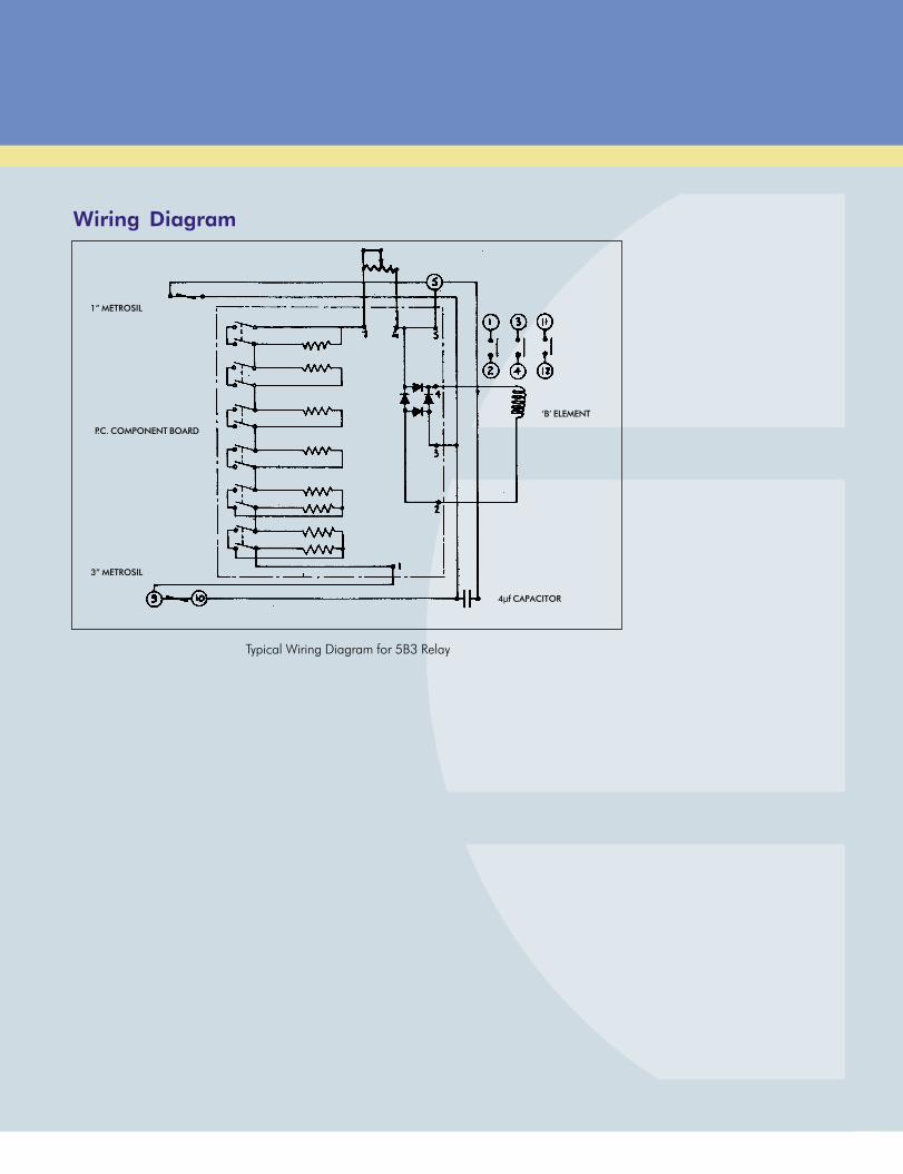
Wiring Diagram
Typical Wiring Diagram for 5B3 Relay
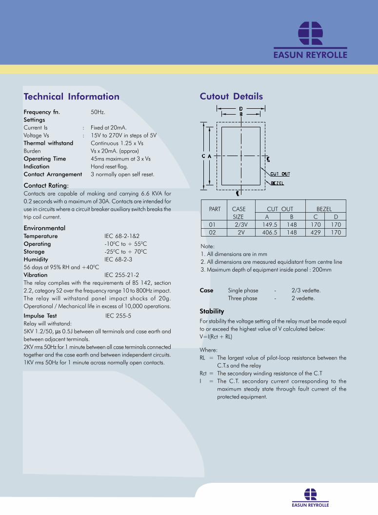
Cutout Details
Case Single phase - 2/3 vedette.
Three phase - 2 vedette.
Stability
For stability the voltage setting of the relay must be made equal
to or exceed the highest value of V calculated below:
V=I(Rct + RL)
Where:
RL = The largest value of pilot-loop resistance between the
C.T.s and the relay
Rct = The secondary winding resistance of the C.T
I = The C.T. secondary current corresponding to the
maximum steady state through fault current of the
protected equipment.
PART CASE CUT OUT BEZEL
SIZE A B C D
01 2/3V 149.5 148 170 170
02 2V 406.5 148 429 170
Note:
1. All dimensions are in mm
2. All dimensions are measured equidistant from centre line
3. Maximum depth of equipment inside panel : 200mm
1” METROSIL
P.C. COMPONENT BOARD
3” METROSIL
‘B’ ELEMENT
4µf CAPACITOR
Technical Information
Frequency fn. 50Hz.
Settings
Current Is : Fixed at 20mA.
Voltage Vs : 15V to 270V in steps of 5V
Thermal withstand Continuous 1.25 x Vs
Burden Vs x 20mA. (approx)
Operating Time 45ms maximum at 3 x Vs
Indication Hand reset flag.
Contact Arrangement 3 normally open self reset.
Contact Rating:Contacts are capable of making and carrying 6.6 KVA for
0.2 seconds with a maximum of 30A. Contacts are intended for
use in circuits where a circuit breaker auxiliary switch breaks the
trip coil current.
EnvironmentalTemperature IEC 68-2-1&2
Operating -100C to + 550C
Storage -250C to + 700C
Humidity IEC 68-2-3
56 days at 95% RH and +400C
Vibration IEC 255-21-2
The relay complies with the requirements of BS 142, section
2.2, category S2 over the frequency range 10 to 800Hz impact.
The relay will withstand panel impact shocks of 20g.
Operational / Mechanical life in excess of 10,000 operations.
Impulse Test IEC 255-5
Relay will withstand:
5KV 1.2/50, µs 0.5J between all terminals and case earth and
between adjacent terminals.
2KV rms 50Hz for 1 minute between all case terminals connected
together and the case earth and between independent circuits.
1KV rms 50Hz for 1 minute across normally open contacts.
Wiring Diagram
Typical Wiring Diagram for 5B3 Relay
Cutout Details
Case Single phase - 2/3 vedette.
Three phase - 2 vedette.
Stability
For stability the voltage setting of the relay must be made equal
to or exceed the highest value of V calculated below:
V=I(Rct + RL)
Where:
RL = The largest value of pilot-loop resistance between the
C.T.s and the relay
Rct = The secondary winding resistance of the C.T
I = The C.T. secondary current corresponding to the
maximum steady state through fault current of the
protected equipment.
PART CASE CUT OUT BEZEL
SIZE A B C D
01 2/3V 149.5 148 170 170
02 2V 406.5 148 429 170
Note:
1. All dimensions are in mm
2. All dimensions are measured equidistant from centre line
3. Maximum depth of equipment inside panel : 200mm
1” METROSIL
P.C. COMPONENT BOARD
3” METROSIL
‘B’ ELEMENT
4µf CAPACITOR
Restricted Earth Fault Relay 5B3
The policy of Easun Reyrolle is one of continuous improvement and development. The company therefore reserves the right to supply equipment,
which may differ slightly from that described and illustrated in this publication.
Description
The relay uses a type B61 attracted armature element energized
via a low pass filter circuit and a full wave rectifier. The relay has
a pre-set setting of 15V. Other resistors are introduced into the
circuit to provide the voltage setting range up to 270V in
increments of 5V using heavy duty DIL switches.
Included within the relays, are the essential non-linear resistors
to limit the peak voltage output from saturated C.T.s, these
resistors protect the C.T. insulation and secondary wiring.
Current Transformer RequirementsExperience has shown that most protective C.T.s are suitable for
use with the high impedance relays and where the C.T.s are
specially designed for this protection, their overall size may be
smaller than that required for an alternative current balance
protection. The basic requirements are:
a) All C.T.s should have identical turns ratios, if possible.
b) The knee point voltage of each C.T. should be at least 2xVs.
The knee point voltage is expressed as the voltage applied to
the secondary circuit with the primary open circuit which when
increased by 10% causes the magnetizing current to increase
by 50%.
c) C.T.s should be of the low leakage reactance type.
Most modern C.T.s are of this type and there is no difficulty in
meeting this requirement. A low leakage reactance C.T. has a
jointless ring type core, the secondary winding evenly
distributed along the whole length of the magnetic circuit and
the primary conductor passes through the approximate centre
of the core.
Applications
Type 5B3 electromagnetic relay is ideal for restricted earth fault
protection of transformer windings or phase and earth fault
protection of reactors and the stator windings of large machines.
This relay may also be used for high impedance busbar protection.
High impedance schemes have the advantages over low
impedance schemes that, a more sensitive setting can be obtained
without any loss of stability and the primary fault setting
calculation is simpler. Current operated schemes are more
susceptible to mal-operations from through faults, unless greater
care is taken with the selection of the current transformer.
Restricted Earth Fault Relay – 5B3
For some restricted earth fault applications the primary fault
setting needs to be greater at harmonic frequencies than the
setting at the fundamental frequency. The 5B3 relay uses a low
pass filter circuit to achieve this. No adverse reduction in fault
setting can occur with the high frequency current, which may be
produced during switching.
Features
• Low settings can be achieved
• Stability based upon plant capacity
Fault Setting
It should, however, be noted that because the operating voltage
of the relay circuit is relatively high, the excitation currents of the
C.T.’s in parallel with the relay may comprise a large proportion
of the fault setting.
Primary fault setting = N (l0 + l
1 + l
2 + l
3)
Where:
I0
= Relay operating current
I1 etc = Excitation current of each C.T at the relay setting voltage
N = C.T. turns ratio
Ordering Information
• For Single Element-2/3V
• For Three Element -2V
Qualification
ISO 9001-2000
FACT
/5B3
/08-
07/R
EV 1
®Easu
n R
eyro
lle-2
007 -
Easu
n R
eyro
lle,
the
Easu
n R
eyro
lle l
ogo a
nd a
ny
alte
rnativ
e ve
rsio
n t
her
eof
are
reg
iste
red t
rade
mark
s and s
ervi
ce m
ark
s of
Easu
n R
eyro
lle
Sales OfficesBangaloreEasun Reyrolle Ltd.#17/3 Arakere, Bannerghatta Road,Bangalore - 560 076, India.Tel: +91 80 26581023/3268Fax: +91 80 26580642Email: [email protected]
BhopalEasun Reyrolle Ltd.H.No.16, Essarjee HomesNear Gopal Nagar, Kalan RoadPiplani, Bhopal - 462 021, India.Telefax: +91 755 2684221Email: [email protected]
ChennaiEasun Reyrolle Ltd.6th Floor, Temple Tower, 672,Anna Salai, NandanamChennai - 600 035, India.Tel: +91 44 24346425/24347608Fax: +91 44 24346435Email: [email protected]
DelhiEasun Reyrolle Ltd.29/12, Ground Floor, East Patel NagarNew Delhi - 110 008, India.Tel: +91 11 25747321/25747322Fax: +91 11 25747320Email: [email protected]
KolkataEasun Reyrolle Ltd.4, Dr.Sundari Mohan Avenue, 5th FloorFlat No.18, Kolkata - 700 014, India.Tel: +91 33 22848320Fax: +91 33 22848326Email: [email protected]
MumbaiEasun Reyrolle Ltd.23, Kasturi Building, Jamshedji Tata RoadMumbai - 400 020, India.Tel: +91 22 22022270/22855415Fax: +91 22 22825703Email: [email protected]
SecunderabadEasun Reyrolle Ltd.#2, 1st Floor, Paradise ChambersOpp Hotel Ambassador1-7-196 Prender Ghast RoadSecunderabad - 500 003, India.Telefax: +91 40 27817847Email: [email protected]
CORPORATE OFFICEEasun Reyrolle Limited.,98 Sipcot Industrial ComplexHosur 635 126, India.Tel: +91 4344 401600/01/02Fax: +91 4344 276397
TURNKEY PROJECTSBUSINESS/AMR BUSINESS#389, “Rasukumaki”, HulimavuBegur Hobli, Bannerghatta RoadBangalore - 560 076, India.Tel: +91 80 40477200/ 201Fax: +91 80 40477202Email: [email protected]
HOSUR WORKS#98, Sipcot Industrial ComplexHosur - 635 126, India.Tel: +91 4344 401600/01/02Fax: +91 4344 276397
CENTRAL MARKETING &EXPORTS BUSINESS#17/3 ArakereBannerghatta RoadBangalore - 560 076, India.Tel: +91 80 26581023/3268Fax: +91 80 26580642Email: [email protected]
BANGALORE WORKS#17/3 Arakere, Bannerghatta RoadBangalore - 560 076, India.Tel: +91 80 26581023/3268Fax: +91 80 26580642Email: [email protected]
AUTOMATION BUSINESS#389, “Rasukumaki”, HulimavuBegur Hobli, Bannerghatta RoadBangalore - 560 076, India.Tel: +91 80 40477200/ 201Fax: +91 80 40477202Email: [email protected]
Corporate OfficeEasun Reyrolle Limited. 98 Sipcot Industrial Complex,
Hosur 635 126 India.Tel: +91 4344 401600/01/02
Fax: +91 4344 276397www.easunreyrolle.com


