
NEDERLANDS 5
ENGLISH 9
DEUTSCH 13
FRANÇAIS 17
ESPAÑOL 21
ITALIANO 25
DANSK 29
SVENSKA 33
NORSK 37
SUOMEKSI 41
Copyright © 2017 Vetus b.v. Schiedam Holland
020574.02
RimDrive RD125 / RD160125 kgf / 160 kgf - ø 250 mm
Bedieningshandleiding
Operation manual
Bedienungshandbuch
Manuel d’utilisation
Manual de manejo
Manuale per l’uso
Betjeningsvejledning
Bruksanvisning
Bruksanvisning
Käyttöohje

2 020574.02 vetus® Operation manual thruster RIM DRIVE 250 mm
Inhoud Content
Inhalt Sommaire
1 Veiligheid . . . . . . . . . . . . . . . . . . . . . . . . . . . . . . . . . . . . . . . . . . . . . . 5
2 Inleiding. . . . . . . . . . . . . . . . . . . . . . . . . . . . . . . . . . . . . . . . . . . . . . . . 5
3 Bediening . . . . . . . . . . . . . . . . . . . . . . . . . . . . . . . . . . . . . . . . . . . . . . 63.1 Algemeen . . . . . . . . . . . . . . . . . . . . . . . . . . . . . . . . . . . . . . . . . 63.2 Inschakelen van een paneel . . . . . . . . . . . . . . . . . . . . . . . . 63.3 Inschakelen van het andere paneel (bij 2 panelen) . . 63.4 Uitschakelen paneel . . . . . . . . . . . . . . . . . . . . . . . . . . . . . . . 63.5 ‘Automatisch uitschakelen’ aanzetten of uitzetten . . . 63.6 Afstandsbediening. . . . . . . . . . . . . . . . . . . . . . . . . . . . . . . . . 7
4 Onderhoud . . . . . . . . . . . . . . . . . . . . . . . . . . . . . . . . . . . . . . . . . . . . . 74.1 Bescherming van de boegschroef tegen corrosie. . . . 74.2 Verwisselen schroef, alleen noodzakelijk na
schade aan de schroef . . . . . . . . . . . . . . . . . . . . . . . . . . . . . 7
5 Storingen. . . . . . . . . . . . . . . . . . . . . . . . . . . . . . . . . . . . . . . . . . . . . . . 8
6 Technische gegevens . . . . . . . . . . . . . . . . . . . . . . . . . . . . . . . . . . . 8
1 Sicherheitsbestimmungen . . . . . . . . . . . . . . . . . . . . . . . . . . . . 13
2 Einleitung . . . . . . . . . . . . . . . . . . . . . . . . . . . . . . . . . . . . . . . . . . . . . 13
3 Betrieb . . . . . . . . . . . . . . . . . . . . . . . . . . . . . . . . . . . . . . . . . . . . . . . . 143.1 Allgemeines . . . . . . . . . . . . . . . . . . . . . . . . . . . . . . . . . . . . . . 143.2 Bedientafel einschalten . . . . . . . . . . . . . . . . . . . . . . . . . . . 143.3 Einschalten einer anderen Bedientafel (im Falle
von 2 Bedientafeln) . . . . . . . . . . . . . . . . . . . . . . . . . . . . . . . 143.4 AUSschalten einer Bedientafel. . . . . . . . . . . . . . . . . . . . . 143.5 Wählen oder abwählen der “automatischen
Abschaltung” . . . . . . . . . . . . . . . . . . . . . . . . . . . . . . . . . . . . . 143.6 Fernbedienung . . . . . . . . . . . . . . . . . . . . . . . . . . . . . . . . . . . 15
4 Wartung . . . . . . . . . . . . . . . . . . . . . . . . . . . . . . . . . . . . . . . . . . . . . . . 154.1 Korrosionsschutz der Bugstrahlruders . . . . . . . . . . . . . 154.2 Schiffsschraubenwechsel (nur bei Beschädigung
notwendig) . . . . . . . . . . . . . . . . . . . . . . . . . . . . . . . . . . . . . . . 15
5 Störungsbehebung . . . . . . . . . . . . . . . . . . . . . . . . . . . . . . . . . . . . 16
6 Technische Daten. . . . . . . . . . . . . . . . . . . . . . . . . . . . . . . . . . . . . . 16
1 Safety measures . . . . . . . . . . . . . . . . . . . . . . . . . . . . . . . . . . . . . . . . 9
2 Introduction . . . . . . . . . . . . . . . . . . . . . . . . . . . . . . . . . . . . . . . . . . . . 9
3 Operation . . . . . . . . . . . . . . . . . . . . . . . . . . . . . . . . . . . . . . . . . . . . . 103.1 General . . . . . . . . . . . . . . . . . . . . . . . . . . . . . . . . . . . . . . . . . . 103.2 Switching on a panel . . . . . . . . . . . . . . . . . . . . . . . . . . . . . . 103.3 Switching on the other panel (in case of 2 panels) . . 103.4 Switching OFF a panel . . . . . . . . . . . . . . . . . . . . . . . . . . . . 103.5 Selecting or deselecting ‘automatic switching-off’
function . . . . . . . . . . . . . . . . . . . . . . . . . . . . . . . . . . . . . . . . . . 103.6 Remote control . . . . . . . . . . . . . . . . . . . . . . . . . . . . . . . . . . . 11
4 Maintenance . . . . . . . . . . . . . . . . . . . . . . . . . . . . . . . . . . . . . . . . . . 114.1 Bow thruster corrosion protection . . . . . . . . . . . . . . . . . 114.2 Changing the propeller (only necessary if the
propeller is damaged). . . . . . . . . . . . . . . . . . . . . . . . . . . . . 11
5 Trouble shooting . . . . . . . . . . . . . . . . . . . . . . . . . . . . . . . . . . . . . . 12
6 Technical data . . . . . . . . . . . . . . . . . . . . . . . . . . . . . . . . . . . . . . . . . 12
1 Sécurité . . . . . . . . . . . . . . . . . . . . . . . . . . . . . . . . . . . . . . . . . . . . . . . 17
2 Introduction . . . . . . . . . . . . . . . . . . . . . . . . . . . . . . . . . . . . . . . . . . . 17
3 Utilisation . . . . . . . . . . . . . . . . . . . . . . . . . . . . . . . . . . . . . . . . . . . . . 183.1 Généralités . . . . . . . . . . . . . . . . . . . . . . . . . . . . . . . . . . . . . . . 183.2 Basculement depuis l’un des panneaux . . . . . . . . . . . . 183.3 Basculer vers l’autre panneau (dans le cas d’une
installation à deux panneaux) . . . . . . . . . . . . . . . . . . . . . 183.4 EXTINCTION d’un panneau . . . . . . . . . . . . . . . . . . . . . . . . 183.5 Sélectionner ou désélectionner la fonction
d’extinction automatique . . . . . . . . . . . . . . . . . . . . . . . . . 183.6 Télécommande . . . . . . . . . . . . . . . . . . . . . . . . . . . . . . . . . . . 19
4 Entretien . . . . . . . . . . . . . . . . . . . . . . . . . . . . . . . . . . . . . . . . . . . . . . 194.1 Protection du propulseur d’étrave contre la
corrosion . . . . . . . . . . . . . . . . . . . . . . . . . . . . . . . . . . . . . . . . . 194.2 Replacement de l’hélice (uniquement si
endommagée) . . . . . . . . . . . . . . . . . . . . . . . . . . . . . . . . . . . . 19
5 Dépannage . . . . . . . . . . . . . . . . . . . . . . . . . . . . . . . . . . . . . . . . . . . . 20
6 Caractéristiques techniques . . . . . . . . . . . . . . . . . . . . . . . . . . . 20
7 Hoofdafmetingen . . . . . . . . . . . . . . . . . . . . . . . . . . . . . . . . . . . . . .45
8 Elektrisch schema . . . . . . . . . . . . . . . . . . . . . . . . . . . . . . . . . . . . . 46
7 Hauptabmessungen . . . . . . . . . . . . . . . . . . . . . . . . . . . . . . . . . . . .45
8 Schaltschema. . . . . . . . . . . . . . . . . . . . . . . . . . . . . . . . . . . . . . . . . . 467 Circuit electrique . . . . . . . . . . . . . . . . . . . . . . . . . . . . . . . . . . . . . . .45
8 Capacité de la batterie . . . . . . . . . . . . . . . . . . . . . . . . . . . . . . . . . 46
7 Principal dimensions . . . . . . . . . . . . . . . . . . . . . . . . . . . . . . . . . . .45
8 Wiring diagram . . . . . . . . . . . . . . . . . . . . . . . . . . . . . . . . . . . . . . . . 46

Índice Indice
Indhold Innehåll
1 Seguridad . . . . . . . . . . . . . . . . . . . . . . . . . . . . . . . . . . . . . . . . . . . . . 21
2 Introducción. . . . . . . . . . . . . . . . . . . . . . . . . . . . . . . . . . . . . . . . . . . 21
3 Funcionamiento . . . . . . . . . . . . . . . . . . . . . . . . . . . . . . . . . . . . . . . 223.1 General . . . . . . . . . . . . . . . . . . . . . . . . . . . . . . . . . . . . . . . . . . 223.2 Encendiendo un panel . . . . . . . . . . . . . . . . . . . . . . . . . . . . 223.3 Encendiendo el otro panel (en el caso de 2 paneles) 223.4 Apagando un panel . . . . . . . . . . . . . . . . . . . . . . . . . . . . . . . 223.5 Seleccionando o deseleccionando la función de
“Apagado automático” . . . . . . . . . . . . . . . . . . . . . . . . . . . . 223.6 Control remoto . . . . . . . . . . . . . . . . . . . . . . . . . . . . . . . . . . . 23
4 Mantenimiento . . . . . . . . . . . . . . . . . . . . . . . . . . . . . . . . . . . . . . . . 234.1 Protección de la hélice de proa contra la corrosión . 234.2 Cambiar la hélice (sólo es necesario si la hélice
está dañada). . . . . . . . . . . . . . . . . . . . . . . . . . . . . . . . . . . . . . 23
5 Solución de problemas . . . . . . . . . . . . . . . . . . . . . . . . . . . . . . . . 24
6 Datos técnicos . . . . . . . . . . . . . . . . . . . . . . . . . . . . . . . . . . . . . . . . . 24
1 Sikkerhed . . . . . . . . . . . . . . . . . . . . . . . . . . . . . . . . . . . . . . . . . . . . . 29
2 Introduktion. . . . . . . . . . . . . . . . . . . . . . . . . . . . . . . . . . . . . . . . . . . 29
3 Betjening . . . . . . . . . . . . . . . . . . . . . . . . . . . . . . . . . . . . . . . . . . . . . . 303.1 Generelt . . . . . . . . . . . . . . . . . . . . . . . . . . . . . . . . . . . . . . . . . 303.2 Sådan tændes et panel . . . . . . . . . . . . . . . . . . . . . . . . . . . . 303.3 Sådan tændes det andet panelet (hvis der er to
paneler) . . . . . . . . . . . . . . . . . . . . . . . . . . . . . . . . . . . . . . . . . . 303.4 Sådan slukkes et panel . . . . . . . . . . . . . . . . . . . . . . . . . . . . 303.5 Vælg eller fravælg ”automatisk sluk”-funktion . . . . . . 303.6 Fjernbetjening . . . . . . . . . . . . . . . . . . . . . . . . . . . . . . . . . . . . 31
4 Vedligeholdelse:. . . . . . . . . . . . . . . . . . . . . . . . . . . . . . . . . . . . . . . 314.1 Bovpropellens rustbeskyttelse. . . . . . . . . . . . . . . . . . . . . 314.2 Udskiftning af propellen (kun nødvendigt hvis
propellen er beskadiget) . . . . . . . . . . . . . . . . . . . . . . . . . . 31
5 3FEJLFINDING . . . . . . . . . . . . . . . . . . . . . . . . . . . . . . . . . . . . . . . . . 32
6 Tekniske data . . . . . . . . . . . . . . . . . . . . . . . . . . . . . . . . . . . . . . . . . . 32
1 Sicurezza . . . . . . . . . . . . . . . . . . . . . . . . . . . . . . . . . . . . . . . . . . . . . . 25
2 Introduzione . . . . . . . . . . . . . . . . . . . . . . . . . . . . . . . . . . . . . . . . . . 25
3 Utilizzo . . . . . . . . . . . . . . . . . . . . . . . . . . . . . . . . . . . . . . . . . . . . . . . . 263.1 Generalità . . . . . . . . . . . . . . . . . . . . . . . . . . . . . . . . . . . . . . . . 263.2 Accendere un pannello. . . . . . . . . . . . . . . . . . . . . . . . . . . . 263.3 Accensione dell’altro pannello (nel caso di 2
pannelli) . . . . . . . . . . . . . . . . . . . . . . . . . . . . . . . . . . . . . . . . . . 263.4 Spegnimento di un pannello . . . . . . . . . . . . . . . . . . . . . . 263.5 Spegnimento dell’interruttore principale quando
si lascia la barca. . . . . . . . . . . . . . . . . . . . . . . . . . . . . . . . . . . 263.6 Telecomando (controllo a distanza) . . . . . . . . . . . . . . . . 27
4 Manutenzione . . . . . . . . . . . . . . . . . . . . . . . . . . . . . . . . . . . . . . . . . 274.1 Protezione dell’elica di prua dalla corrosione . . . . . . 274.2 Cambiare l’elica (necessario solo se l’elica è
danneggiata) . . . . . . . . . . . . . . . . . . . . . . . . . . . . . . . . . . . . . 27
5 Risoluzione dei problemi . . . . . . . . . . . . . . . . . . . . . . . . . . . . . . 28
6 Dati tecnici . . . . . . . . . . . . . . . . . . . . . . . . . . . . . . . . . . . . . . . . . . . . 28
1 Säkerhet. . . . . . . . . . . . . . . . . . . . . . . . . . . . . . . . . . . . . . . . . . . . . . . 33
2 Inledning . . . . . . . . . . . . . . . . . . . . . . . . . . . . . . . . . . . . . . . . . . . . . . 33
3 Drift . . . . . . . . . . . . . . . . . . . . . . . . . . . . . . . . . . . . . . . . . . . . . . . . . . . 343.1 Allmänt . . . . . . . . . . . . . . . . . . . . . . . . . . . . . . . . . . . . . . . . . . 343.2 Slå på en panel . . . . . . . . . . . . . . . . . . . . . . . . . . . . . . . . . . . 343.3 Slå på den andra panelen (i fallet med 2 paneler). . . 343.4 Stänga av en panel. . . . . . . . . . . . . . . . . . . . . . . . . . . . . . . . 343.5 Markering eller avmarkering med funktionen
’Automatisk avstängning’. . . . . . . . . . . . . . . . . . . . . . . . . . 343.6 Fjärrkontroll . . . . . . . . . . . . . . . . . . . . . . . . . . . . . . . . . . . . . . 35
4 Underhåll. . . . . . . . . . . . . . . . . . . . . . . . . . . . . . . . . . . . . . . . . . . . . . 354.1 Bogpropellerns rostbeständigt skydd. . . . . . . . . . . . . . 354.2 Byte av propeller (endast nödvändigt om
propellern är skadad) . . . . . . . . . . . . . . . . . . . . . . . . . . . . . 35
5 Felsökning . . . . . . . . . . . . . . . . . . . . . . . . . . . . . . . . . . . . . . . . . . . . 36
6 Tekniska data. . . . . . . . . . . . . . . . . . . . . . . . . . . . . . . . . . . . . . . . . . 36
7 Mål . . . . . . . . . . . . . . . . . . . . . . . . . . . . . . . . . . . . . . . . . . . . . . . . . . . . .45
8 Elektrisk skema . . . . . . . . . . . . . . . . . . . . . . . . . . . . . . . . . . . . . . . . 46
7 Huvudmått . . . . . . . . . . . . . . . . . . . . . . . . . . . . . . . . . . . . . . . . . . . . .45
8 Kopplingsschema . . . . . . . . . . . . . . . . . . . . . . . . . . . . . . . . . . . . . 46
7 Dimensiones principales. . . . . . . . . . . . . . . . . . . . . . . . . . . . . . . .45
8 Esquema eléctrico . . . . . . . . . . . . . . . . . . . . . . . . . . . . . . . . . . . . . 467 Schema elettrico. . . . . . . . . . . . . . . . . . . . . . . . . . . . . . . . . . . . . . . .45
8 Batterikapacitet . . . . . . . . . . . . . . . . . . . . . . . . . . . . . . . . . . . . . . . 46
Innhold Sisältö
1 Sikkerhet . . . . . . . . . . . . . . . . . . . . . . . . . . . . . . . . . . . . . . . . . . . . . . 37
2 Introduksjon . . . . . . . . . . . . . . . . . . . . . . . . . . . . . . . . . . . . . . . . . . 37
3 Drift . . . . . . . . . . . . . . . . . . . . . . . . . . . . . . . . . . . . . . . . . . . . . . . . . . . 383.1 Generelt . . . . . . . . . . . . . . . . . . . . . . . . . . . . . . . . . . . . . . . . . 383.2 Slå på et panel . . . . . . . . . . . . . . . . . . . . . . . . . . . . . . . . . . . . 383.3 Skru på det andre panelet (i tilfelle to paneler) . . . . . 383.4 Slå AV et panel . . . . . . . . . . . . . . . . . . . . . . . . . . . . . . . . . . . . 383.5 Aktivere eller deaktivere ’automatisk
avkoblingfunksjon’. . . . . . . . . . . . . . . . . . . . . . . . . . . . . . . . 383.6 Fjernkontroll . . . . . . . . . . . . . . . . . . . . . . . . . . . . . . . . . . . . . . 39
4 Vedlikehold . . . . . . . . . . . . . . . . . . . . . . . . . . . . . . . . . . . . . . . . . . . 394.1 Baugthruster korrosjonsbeskyttelse . . . . . . . . . . . . . . . 394.2 Erstatting av propellen (kun dersom propellen er
skadd) . . . . . . . . . . . . . . . . . . . . . . . . . . . . . . . . . . . . . . . . . . . . 39
5 Feilsøking . . . . . . . . . . . . . . . . . . . . . . . . . . . . . . . . . . . . . . . . . . . . . 40
6 Teknisk data . . . . . . . . . . . . . . . . . . . . . . . . . . . . . . . . . . . . . . . . . . . 40
1 Turvallisuus . . . . . . . . . . . . . . . . . . . . . . . . . . . . . . . . . . . . . . . . . . . 41
2 Johdanto . . . . . . . . . . . . . . . . . . . . . . . . . . . . . . . . . . . . . . . . . . . . . . 41
3 Käyttö . . . . . . . . . . . . . . . . . . . . . . . . . . . . . . . . . . . . . . . . . . . . . . . . . 423.1 Yleistä . . . . . . . . . . . . . . . . . . . . . . . . . . . . . . . . . . . . . . . . . . . . 423.2 Käynnistäminen paneelissa. . . . . . . . . . . . . . . . . . . . . . . . 423.3 Toinen paneelin kytkeminen päälle (jos 2 paneelia) 423.4 Paneelin sammuttaminen . . . . . . . . . . . . . . . . . . . . . . . . . 423.5 Automaattisen sammutuksen valitseminen tai
valinnan poistaminen . . . . . . . . . . . . . . . . . . . . . . . . . . . . . 423.6 Kaukosäädin . . . . . . . . . . . . . . . . . . . . . . . . . . . . . . . . . . . . . . 43
4 Kunnossapito. . . . . . . . . . . . . . . . . . . . . . . . . . . . . . . . . . . . . . . . . . 434.1 Keulapotkurin korroosiosuojaus . . . . . . . . . . . . . . . . . . . 434.2 Potkurin vaihtaminen (tarpeen vain jos potkuri on
vaurioitunut) . . . . . . . . . . . . . . . . . . . . . . . . . . . . . . . . . . . . . 43
5 Vianetsintä . . . . . . . . . . . . . . . . . . . . . . . . . . . . . . . . . . . . . . . . . . . . 44
6 Tekniset tiedot . . . . . . . . . . . . . . . . . . . . . . . . . . . . . . . . . . . . . . . . 44
7 Viktigste mål . . . . . . . . . . . . . . . . . . . . . . . . . . . . . . . . . . . . . . . . . . .45
8 Elektrisk skjema . . . . . . . . . . . . . . . . . . . . . . . . . . . . . . . . . . . . . . . 46
7 Päämitat. . . . . . . . . . . . . . . . . . . . . . . . . . . . . . . . . . . . . . . . . . . . . . . .45
8 Sähkökaavio. . . . . . . . . . . . . . . . . . . . . . . . . . . . . . . . . . . . . . . . . . . 46
020574.02 9vetus® Operation manual thruster RIM DRIVE 250 mm
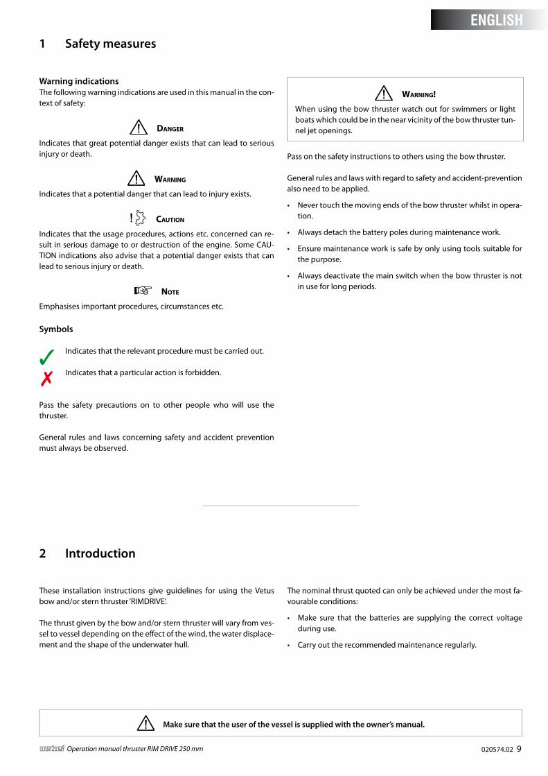
Warning indicationsThe following warning indications are used in this manual in the con-text of safety:
Danger
Indicates that great potential danger exists that can lead to serious injury or death.
Warning
Indicates that a potential danger that can lead to injury exists.
Caution
Indicates that the usage procedures, actions etc. concerned can re-sult in serious damage to or destruction of the engine. Some CAU-TION indications also advise that a potential danger exists that can lead to serious injury or death.
note
Emphasises important procedures, circumstances etc.
Symbols
Indicates that the relevant procedure must be carried out.
Indicates that a particular action is forbidden.
Pass the safety precautions on to other people who will use the thruster.
General rules and laws concerning safety and accident prevention must always be observed.
Warning!
When using the bow thruster watch out for swimmers or light boats which could be in the near vicinity of the bow thruster tun-nel jet openings.
Pass on the safety instructions to others using the bow thruster.
General rules and laws with regard to safety and accident-prevention also need to be applied.
• Never touch the moving ends of the bow thruster whilst in opera-tion.
• Always detach the battery poles during maintenance work.
• Ensure maintenance work is safe by only using tools suitable for the purpose.
• Always deactivate the main switch when the bow thruster is not in use for long periods.
These installation instructions give guidelines for using the Vetus bow and/or stern thruster ‘RIMDRIVE’.
The thrust given by the bow and/or stern thruster will vary from ves-sel to vessel depending on the effect of the wind, the water displace-ment and the shape of the underwater hull.
The nominal thrust quoted can only be achieved under the most fa-vourable conditions:
• Make sure that the batteries are supplying the correct voltage during use.
• Carry out the recommended maintenance regularly.
1 Safety measures
2 Introduction
Make sure that the user of the vessel is supplied with the owner’s manual.
ENGLISH
10 020574.02 vetus® Operation manual thruster RIM DRIVE 250 mm
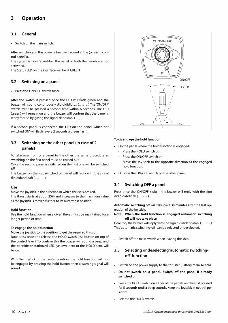
3.1 General
• Switch on the main switch.
After switching on the power a beep will sound at the (or each) con-trol panel(s). The system is now ‘stand-by’. The panel or both the panels are not activated.The Status LED on the interface will be lit GREEN.
3.2 Switching on a panel
• Press the ‘ON/OFF’ switch twice.
After the switch is pressed once the LED will flash green and the buzzer will sound continuously didididididi..... (. . . . . . .) The ‘ON/OFF’ switch must be pressed a second time within 6 seconds. The LED (green) will remain on and the buzzer will confirm that the panel is ready for use by giving the signal dahdidah (- . -).
If a second panel is connected the LED on the panel ‘which not switched ON’ will flash (every 2 seconds a green flash).
3.3 Switching on the other panel (in case of 2 panels)
To take over from one panel to the other the same procedure as switching on the first panel must be carried out.Once the second panel is switched on the first one will be switched off.The buzzer on the just switched off panel will reply with the signal didididahdidah ( . . . - . - ).
UseMove the joystick in the direction in which thrust is desired.The thrust starts at about 25% and increases to the maximum value as the joystick is moved further to its outermost position.
Hold functionUse the hold function when a given thrust must be maintained for a longer period of time.
To engage the hold functionMove the joystick to the position to get the required thrust.Now press once and release the HOLD switch (the button on top of the control lever). To confirm this the buzzer will sound a beep and the portside or starboard LED (yellow), next to the ‘HOLD’ text, will be on.
With the joystick in the center position, the hold function will not be engaged by pressing the hold button, then a warning signal will sound.
To disengage the hold function:
• On the panel where the hold function is engaged:
• Press the HOLD switch or,
• Press the ON/OFF switch or,
• Move the joy-stick to the opposite direction as the engaged hold function.
• Or press the ON/OFF switch on the other panel.
3.4 Switching OFF a panel
Press once the ‘ON/OFF’ switch, the buzzer will reply with the sign didididahdidah ( . . . - . - ).
Automatic switching off will take pace 30 minutes after the last op-eration of the joystick.Note: When the hold function is engaged automatic switching
off will not take place.Here too, the buzzer will reply with the sign didididahdidah ( . . . - . - )This ‘automatic switching-off’ can be selected or deselected.
• Switch off the main switch when leaving the ship.
3.5 Selecting or deselecting ‘automatic switching-off’ function
• Switch on the power supply to the thruster (Battery main switch).
• Do not switch on a panel. Switch off the panel if already switched on.
• Press the HOLD switch on either of the panels and keep it pressed for 5 seconds until a beep sounds. Keep the joystick in neutral po-sition!
• Release the HOLD switch.
3 Operation
ON/OFF
HOLD

020574.02 11vetus® Operation manual thruster RIM DRIVE 250 mm
Check the bow thruster 6 weeks after installation and subsequent-ly check the following at least once a year:
- all electric connections between the battery/batteries and the bow thrust-er.
- the lashing straps and the bolts of the lashing straps; apply the indicated torque to the lashing strap bolts.
The instructions of the manufacturer should be followed for the maintenance of the batteries. Vetus batteries are main-tenance free.
The following maintenance should be carried out during a slipway service:
• Check the cathodic Protection and if necessary renew the anode; art. code for the anode: RD100.
• Use a screwdriver to re-move the plastic cover (1).
• Remove the 3 Allen screws to replace the anode (2).
• Reinstall the plastic cover (1).
4 Maintenance
4.1 Bow thruster corrosion protection
To prevent corrosion, never use anti-fouling containing copper oxide.Cathodic protection is absolutely necessary for the preservation of all metal components below water level.The ‘RimDrive’ housing has been fitted with a anode to protect it against corrosion.
4.2 Changing the propeller (only necessary if the propeller is damaged)
Changing the propeller is only necessary if the propeller has been damaged!
• With the boat out of the water, remove the ‘RimDrive’ from the tunnel.
• Remove the bolts used for mounting the round flange and re-move the round flange.
• Now the propeller can be removed.
Warning
The rim of the propeller contains very strong (neodymium) mag-nets, so be very careful when mounting or dismantling the propel-ler.Pay attention when using (steel) tools. The magnets can also ad-versely affect bankcards.
The ON/OFF led will be on, either RED or GREEN.
Ignore the flashing Portside and Starboard LED’s!
To change the setting:
• Use the ON/OFF switch to let the ON/OFF LED toggle between RED and GREEN.GREEN: ‘Automatic switching off’ selected.RED: ‘Automatic switching off’ deselected.
To exit the settings procedure:
• Press the HOLD switch, with the joystick in neutral position, and keep it pressed for 2 seconds until a beep sounds. (Or switch the power off and on again.)
The setting for ‘Automatic switching off’ will be kept in memory even if the power supply is switched off for a very long time.
3.6 Remote control
When using a remote control, the bow thruster can only be engaged at maximum thrust to either port or starboard.
note
The panel to which the (wireless) remote control is connected must be switched on to enable the use of the remote control.
2
1
ENGLISH

12 020574.02 vetus® Operation manual thruster RIM DRIVE 250 mm
5 Trouble shooting
Thruster does nothing
- Check that the battery main switch is ‘ON’.
- Check if the battery voltage is correct (33.6 - 57.6 Volt).
- The battery capacity is reduced because of very low temperatures.
- Check whether the control panel fuse has burnt out.
- Check if one of the main fuses has burnt out.
In all the above cases, the ‘POWER’ indicator LED is not lit.
- There is an overload condition.
The panel gives a warning signal three times ( . - . . - ) and the LED will glow red.
As soon as the controller has cooled down enough, the LED will resume glowing green and the bow thruster can be put back in service.
Check if it is possible to turn the propeller. A piece of wood or similar could have been caught between the propeller and the tunnel.
Control panel fuse is burnt out
- Short circuit in the operating circuit; check the wiring.
6 Technical data
Type : RD125 RD160
Drive
Type :Brushless Permanent Magnet DC
Motor
Voltage : 48 V DC
Current : 130 A 200 A
Rated output : 7 kW 11 kW
No. of revolutions : 1100 rpm 1250 rpm
Rating : S1 (100% duty cycle)
Protection : IP65
Motors conform to CE (2014/30/EU, EMC - EN55011/EN61000)
Housing : Aluminium
PropellerDiameter : 246 mm (9 11/16”)
No. of blades : 6
Profile : asymmetrical
Material : polyacetal (Delrin ®)
Rated thrust :1250 N
(125 kgf, 281 lbf )1600 N
(160 kgf, 36 lbf )
Control circuitFuse : 5 A
Thrust-tunnelSteel model
dimensions : O.D. 267 mm, wall thickness 7.1 mm
treatment : blasted, coated with: SikaCor Steel
Protect. Suitable for all kinds of protection systems.
Plastic model
dimensions : O.D. 264 mm, wall thickness 7 mm
material : glass fibre reinforced polyester
Aluminium model
dimensions : O.D. 264 mm, wall thickness 7 mm
material :aluminium, 6061 or 6062
(AlMg1SiCu)
WeightExcl. thrust-tunnel : 36 kg (80 lbs)
020574.02 45vetus® Operation manual thruster RIM DRIVE 250 mm
L
MIN
. 25
0(1
0 “)
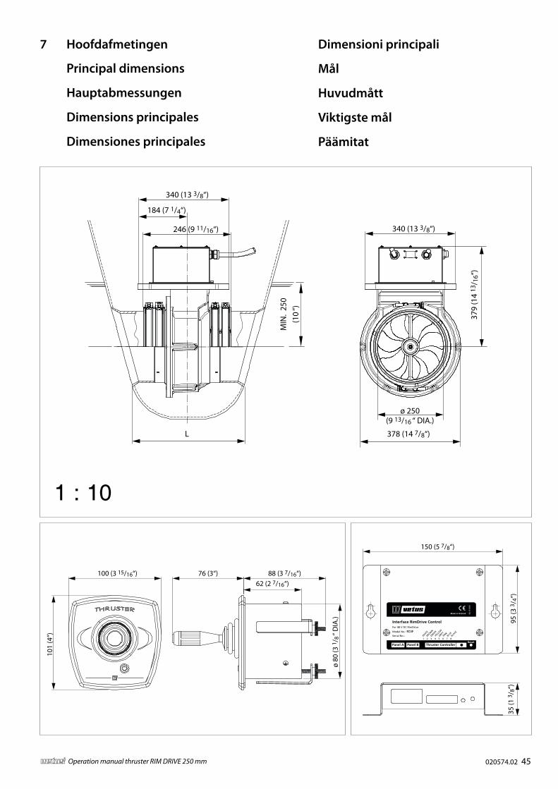
340 (13 3/8“)
184 (7 1/4“)
246 (9 11/16“) 340 (13 3/8“)
379
(14
13/ 1
6“)
378 (14 7/8“)
ø 250(9 13/16 “ DIA.)
1 : 10
7 Hoofdafmetingen
Principal dimensions
Hauptabmessungen
Dimensions principales
Dimensiones principales
Dimensioni principali
Mål
Huvudmått
Viktigste mål
Päämitat
100 (3 15/16“) 88 (3 7/16“)
101
(4“)
76 (3“)62 (2 7/16“)
ø 80
(3 1
/ 8 “
DIA
.)
150 (5 7/8“)
95 (3
3/ 4
“)35
(1 3
/ 8“)
Thruster Controller
RD
1510
59
Interface RimDrive Control
1 2 3 4 5 6 7 8
Model No.: RDIF
Panel A Panel B
WHITE
BROWN
GREEN
YELLO
W
GREYPIN
KBLU
EBLA
CK
Reset
Serial No.:
Made in Holland
For 48 V DC RimDrive

46 020574.02 vetus® Operation manual thruster RIM DRIVE 250 mm
1 Hoofdschakelaar Main switch Hauptschalter Interrupteur principal Interruptor principal 1 Interruttore principale Primære afbryder. Huvudströmbrytare Hovedbryter Pääkytkin
2 Hoofdrelais Main relay Hauptrelais Relais principal Relé principal 2 Relè principale Primære relæ Huvudrelä Hovedrelé Päärele
3 Hoofdzekering Main fuse Hauptsicherung Fusible principal Fusible principal 3 Fusibile principale Primære sikring Huvudsäkring Hovedsikring Pääsulake
4 Stuurstroomzekering Control current fuse SteuerstromsicherungFusible de courant de commande
Fusible de controlde la corriente
4Fusibile corrente di controllo
Kontrolspænding sikring
Säkring för styrströmKontroll nåværende sikring
Ohjausvirran sulake
5 Steker Plug Stecker Prise de courant Enchufe 5 Spina Stik Kontakt Plugg Pistoke
6 Thruster Thruster Strahlruder Propulseur Propulsor 6 Elica Propel Styrpropeller Thruster Potkuri
7 Interface Interface Schnittstelle Interface Interface 7 Interfaccia Stik Gränssnitt Grensesnitt Liittymä
8 Bedieningspaneel Control panel Bedientafel Panneau de contrôle Panel de control 8 Pannello di controllo Kontrolpanel Kontrollpanelen Kontrollpanel Ohjauspaneeli
9 Accu Battery Batterie Batterie Batería 9 Batteria Batteri Batteri Batteri Akku
10 Laadaansluiting Charge connection LadeanschlussRaccordement de charge
Conexión de carga 10 Connessione di carica Ladestik Laddningsanslutning Ladetilkobling Latausliitäntä
+48 V
9
1
3
4
2
+
−
5#1
#2#3
6
10
8 Elektrisch schema
Wiring diagram
Schaltschema
Circuit electrique
Esquema eléctrico
Schema elettrico
Elektrisk skema
Kopplingsschema
Elektrisk skjema
Sähkökaavio
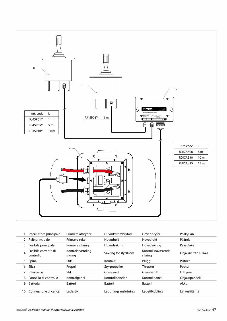
020574.02 47vetus® Operation manual thruster RIM DRIVE 250 mm
1 Hoofdschakelaar Main switch Hauptschalter Interrupteur principal Interruptor principal 1 Interruttore principale Primære afbryder. Huvudströmbrytare Hovedbryter Pääkytkin
2 Hoofdrelais Main relay Hauptrelais Relais principal Relé principal 2 Relè principale Primære relæ Huvudrelä Hovedrelé Päärele
3 Hoofdzekering Main fuse Hauptsicherung Fusible principal Fusible principal 3 Fusibile principale Primære sikring Huvudsäkring Hovedsikring Pääsulake
4 Stuurstroomzekering Control current fuse SteuerstromsicherungFusible de courant de commande
Fusible de controlde la corriente
4Fusibile corrente di controllo
Kontrolspænding sikring
Säkring för styrströmKontroll nåværende sikring
Ohjausvirran sulake
5 Steker Plug Stecker Prise de courant Enchufe 5 Spina Stik Kontakt Plugg Pistoke
6 Thruster Thruster Strahlruder Propulseur Propulsor 6 Elica Propel Styrpropeller Thruster Potkuri
7 Interface Interface Schnittstelle Interface Interface 7 Interfaccia Stik Gränssnitt Grensesnitt Liittymä
8 Bedieningspaneel Control panel Bedientafel Panneau de contrôle Panel de control 8 Pannello di controllo Kontrolpanel Kontrollpanelen Kontrollpanel Ohjauspaneeli
9 Accu Battery Batterie Batterie Batería 9 Batteria Batteri Batteri Batteri Akku
10 Laadaansluiting Charge connection LadeanschlussRaccordement de charge
Conexión de carga 10 Connessione di carica Ladestik Laddningsanslutning Ladetilkobling Latausliitäntä
Art. code L
RDICAB06 6 m
RDICAB10 10 m
RDICAB15 15 m
Art. code L
RJ45P01Y 1 m
RJ45P05Y 5 m
RJ45P10Y 10 m
RJ45P01Y 1 m
6
8
87
Thruster Controller
RD
1510
59
Interface RimDrive Control
1 2 3 4 5 6 7 8
Model No.: RDIF
Panel A Panel B
WHITE
BROWN
GREEN
YELLO
W
GREYPIN
KBLU
EBLA
CK
Reset
Serial No.:
Made in Holland
For 48 V DC RimDrive

vetus b.v.FOKKERSTRAAT 571 - 3125 BD SCHIEDAM - HOLLANDTEL.: +31 0(0)88 4884700 - [email protected] - www.vetus.com
Printed in the Netherlands020574.02 2017-01


![T-61.3010 Digital Signal Processing and Filtering T-61 ... DSP 2009 5/170 NOTATIONS T-61.3010 Digital Signal Processing and Filtering Notations Notation Explanation suomeksi x[n] input](https://cdn.vdocument.in/doc/165x107/5ade4bfa7f8b9a8b6d8e0f68/t-613010-digital-signal-processing-and-filtering-t-61-dsp-2009-5170-notations.jpg)


