Download - Riverclack - System guidelines

GU
IDE
LIN
ES
SHAPING ROOFS

01 RIVERCLACK SHAPING ROOFS
PRODUCT OVERVIEW 02
Riverclack key features 03 Unrivalled watertightness 04 Performance standard / tests and certifi cations 05
METAL CHOICE 06
Metal linear expansion coeffi cients 07
SYSTEM COMPONENTS 08
Metal sheets 09 Fixing clips 10 COLORS AND FINISHINGS 11
Non-coated material fi nishes 12Riverclack color coatings 13
LOADS AND WALKABILITY 18
Walkability: dealing with point loads 18Evenly distributed negative load: wind 20Evenly distributed positive loads: snow 23
TRANSPORT / HANDLING AND STORAGE 26
Packing 26Transport 28Handling 30Storage 32
INSTALLATION 33
Support elements 33 Installation procedure 36 THERMAL MOVEMENTS AND FIXED POINTS 37
Fixed points 38 ON-SITE PRODUCTION 40
Features of the mobile profi ling units (mpu) and curving machines (cv) 41On-site profi ling 42Onsite curving 44 On-site profi ling of tapered sheets 46
OPERATION AND MAINTENANCE 48
Inspections 49Cleaning 49Maintenance 50

02
PRODUCTOVERVIEWRiverclack is a “secret fi x” standing seam metal roof system that has proven itself in the most challenging climate conditions worldwide. The metal sheets can be roll formed on site to any length, removing the need for end laps on long slopes. The joint between two adjacent sheets features a drainage channel that
eliminates any risk of leaks into the building. While the unique perforation-free locking action means that the system s installed onto purpose-designed clips by foot pressure alone, with no need for specialist installation machines.
03 RIVERCLACK SHAPING ROOFS
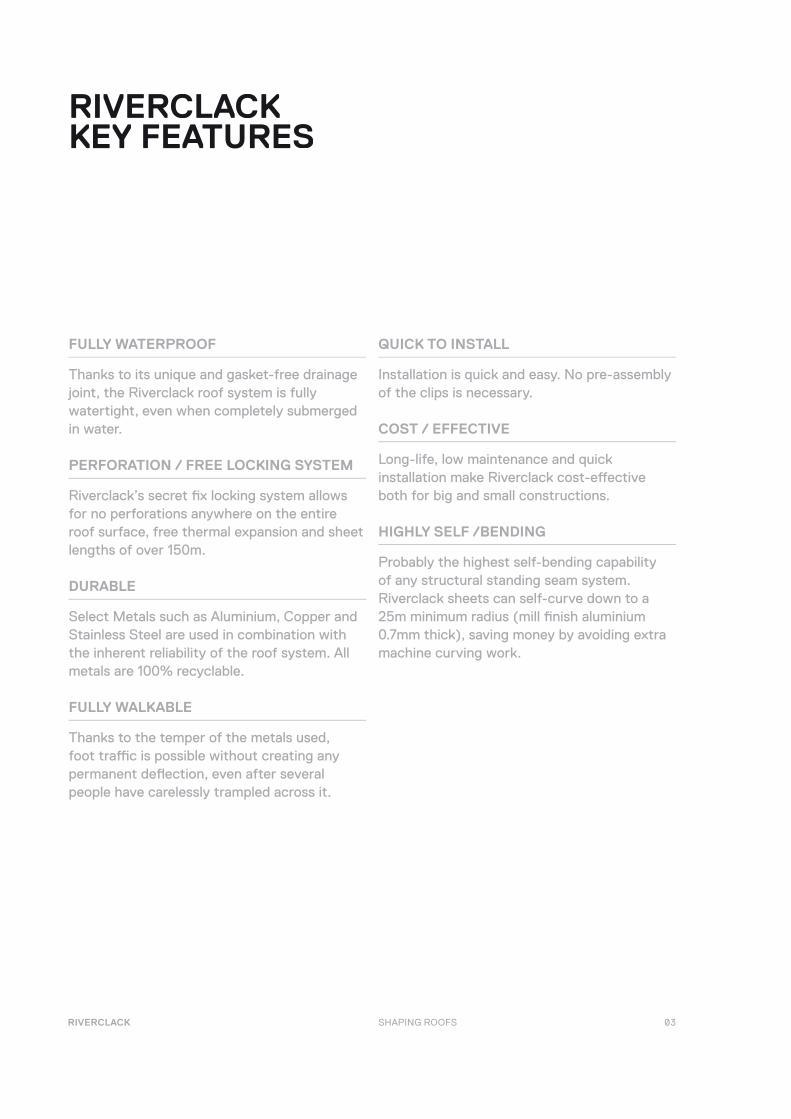
FULLY WATERPROOF
Thanks to its unique and gasket-free drainage joint, the Riverclack roof system is fully watertight, even when completely submerged in water.
PERFORATION / FREE LOCKING SYSTEM
Riverclack’s secret fi x locking system allows for no perforations anywhere on the entire roof surface, free thermal expansion and sheet lengths of over 150m.
DURABLE
Select Metals such as Aluminium, Copper and Stainless Steel are used in combination with the inherent reliability of the roof system. All metals are 100% recyclable.
FULLY WALKABLE
Thanks to the temper of the metals used, foot traffi c is possible without creating any permanent defl ection, even after several people have carelessly trampled across it.
QUICK TO INSTALL
Installation is quick and easy. No pre-assembly of the clips is necessary.
COST / EFFECTIVE
Long-life, low maintenance and quick installation make Riverclack cost-eff ective both for big and small constructions.
HIGHLY SELF /BENDING
Probably the highest self-bending capability of any structural standing seam system. Riverclack sheets can self-curve down to a 25m minimum radius (mill fi nish aluminium 0.7mm thick), saving money by avoiding extra machine curving work.
RIVERCLACKKEY FEATURES

04
UNRIVALLED WATER-TIGHTNESS
Riverclack has been designed to be fully watertight even when completely submerged in water. The secret fi x locking system prevents any through fi xation. But the features that really set Riverclack® apart from the competition are the high tensile, anti-capillary conical joint side lap and the drainage channel (Riverclack®500 and Riverclack® 550).
1. 2. 3.
The high tensile side lap prevents any easy water penetration into the joint. And even if this should happen, the drainage channel then captures the water and runs it to the gutter, eliminating the risk of leaks into the building.
Water tightness has been tested according to the following American ASTM standards:
ASTM E-1646-95 Test Method for Water Penetration of Exterior Metal Roof Panel Systems by Uniform Static Air Pressure Diff erence: for this standard, water is sprayed at the exterior face of the sheets simultaneously with the application of a static air pressure diff erence between the exterior and interior faces (pressure on the outside being kept higher).
ASTM E-2140-01 Test Method for Water Penetration of Metal Roof Panel Systems by Static Water Pressure Head: for this standard the Riverclack roof sample is subjected to a static water pressure head (determined by 150mm of water) applied to the outside face of the roof panel.
In addition Riverclack® has been subjected at the ISCOM facility to a hugely demanding test for any product: a pool was built using Riverclack®550 as the pool base and no additional side lap sealants. The pool was then fi lled with 300mm of water, completely submerging the Riverclack®. After 45 days left in this condition not one single drop of water leaked through.

05 RIVERCLACK SHAPING ROOFS
PERFORMANCE STANDARD /TESTS ANDCERTIFICATIONS
In addition to the above-mentioned ASTM standards for testing its water-tightness, Riverclack® has been tested against many other international standards, including:
ASTM E-2140-01 TEST METHOD FOR WATER PENETRATION OF METAL ROOF PANEL SYSTEMS BY STATIC WATER PRESSURE HEAD
ASTM E-1646-95 TEST METHOD FOR WATER PENETRATION OF EXTERIOR METAL ROOF PANEL SYSTEMS BY UNIFORM STATIC AIR PRESSURE DIFFERENCE
ASTM E-1680-95 TEST METHOD FOR RATE OF AIR LEAKAGE THROUGH EXTERIOR METAL ROOF PANEL SYSTEM
ASTM E-1592-01 TEST METHOD FOR STRUCTURAL PERFORMANCE OF SHEET METAL ROOF AND SIDING SYSTEMS BY UNIFORM STATIC AIR PRESSURE DIFFERENCE
ASTM E-108-07A SPREAD OF FLAME TEST, CLASS A
UL-580 TESTS FOR UPLIFT RESISTANCE OF ROOF ASSEMBLIES, CLASS: UL 90
FM-4471 SIMULATED WIND UPLIFT PRESSURE TEST CLASS: I-75, I-225
TEST METHOD FOR DETERMINING THE SUSCEPTIBILITY TO HAIL DAMAGE OF ROOF COVERINGS, CLASS SH
FOOT TRAFFIC RESISTANCE TEST PROCEDURES, NO DAMAGE
The DIBt (Deutsche Insitute fut Bautechnik), BBA (British Board of Agrement), CSTB (Centre Scientifi que et Technique du Bâtiment), TÜV Rheinland, FM Approvals have certifi ed the Riverclack system according to the above-mentioned and other standards (DIN, EN, UNI, IEC). in the UK for material manufactured
by CA group with the trade-name of River-Therm

06
METALCHOICE Riverclack® can be used with a wide range of metals. Besides the superior aluminium alloy 5754 (guaranteed to deliver unrivalled performance in terms of corrosion resistance, mechanical strength and cost-eff ectiveness), Riverclack® can also be used with Copper, Stainless Steel and Titan Zinc.
MATERIAL THICKNESS USED* NOTES
ALUMINIUM ALLOY 5754 0.7 / 0.8 / 1.0 LIGHT, STRONG AND RUSTPROOF, THIS IS THE MOST COST-EFFECTIVE SOLUTION.
ON CONTACT WITH AIR, ALUMINIUM IS RAPIDLY COVERED WITH A TOUGH,
TRANSPARENT LAYER OF ALUMINIUM OXIDE THAT RESISTS FURTHER CORROSIVE
ACTION, ENSURING A VERY LONG LIFESPAN FOR YOUR ROOF.
ITS SPECIFIC WEIGHT IS ABOUT 1/3 THAT OF STEEL. AS REPORTED IN VARIOUS
SCIENTIFIC ARTICLES, THE MAGNESIUM-BASED ALLOY EN AW 5754 H18 USED FOR
THE MANUFACTURING OF RIVERCLACK® ROOF SHEETS HAS, A HIGHER CORROSION
RESISTANCE THAN OTHER ALLOYS COMMONLY USED FOR ROOFING PURPOSES.
COPPER 0.6 / 0.7 / 0.8 AN ELEGANT MATERIAL THAT IS HIGHLY CORROSION-RESISTANT. IT DEVELOPS A
PATINA WHEN IT WEATHERS THAT CAN VARY FROM GOLD/BROWN SHADES TO BLUE/
GREEN TONES, PROVIDING A UNIQUE AESTHETIC. IT IS USED FOR RIVERCLACK® IN A
RAW PHYSICAL STATE, ENSURING SUPERIOR TOUGHNESS AND ELASTICITY.
STAINLESS STEEL 0.5 / 0.6 / 0.7 ITS SUPERIOR CORROSION RESISTANCE IS A RESULT OF A STABLE AND HIGHLY RE-
SISTANT LAYER OF CHROME OXIDE ON ITS SURFACE THAT PREVENTS ANY CONTACT
BETWEEN THE ENVIRONMENT AND THE STEEL’S INTERIOR. THE DIFFERENCE WITH
COMMON SURFACE PROTECTIVE TREATMENTS, SUCH AS GALVANIZATION OR COAT-
ING, IS THAT THE PROTECTIVE OXIDE LAYER IS ABLE TO REGENERATE EVEN AFTER
NUMEROUS BREAKS.
GALVANIZED STEEL 0.5 / 0.6 / 0.7 FOR STEELS THAT CANNOT PRODUCE A SELF-PROTECTIVE LAYER IN THE WAY
STAINLESS STEEL DOES, A PROTECTIVE ZINC COATING PROVIDES THE EXPOSED
STEEL WITH CATHODIC PROTECTION FROM THE POTENTIALLY AGGRESSIVE EN-
VIRONMENT. SO THAT IF THE SURFACE IS DAMAGED, IT IS THE ZINC RATHER THAN
THE STEEL THAT WILL CORRODE. AN EXTRA PROTECTIVE COLOR COATING IS OFTEN
APPLIED TO GALVANIZED STEEL.
TITAN ZINC 0.8 / 1.0 THIS TITAN-ZINC-COPPER ALLOY HAS A ZINC RATE CLOSE TO 99.995%: THE OTHER
ELEMENTS CAN BE SEEN AS “IMPURITIES” IN THE ZINC. THE MATERIAL IS CHAR-
ACTERIZED BY A HIGH DEGREE OF RESISTANCE TO ATMOSPHERIC CORROSION,
THANKS TO ITS PASSIVATING LAYER. TITAN ZINC IS A HIGHLY EXPRESSIVE MATERIAL
WITH THE COLOR SHADES OF ITS GRAY PATINA PROVIDING A STRONG AESTHETIC
QUALITY. BECAUSE IT IS MALLEABLE, UNLIKE ANY OTHER RIVERCLACK® METAL IT
DOES REQUIRE A RIGID BACK SUPPORT TO ALLOW WALKABILITY.
*UNDERLINE =
STANDARD THICKNESSES

07 RIVERCLACK SHAPING ROOFS
METAL LINEAR EXPANSION COEFFICIENTS
When an object is heated or cooled, its length changes in proportion to the original length and change in temperature. The key factor for a Riverclack sheet is the linear thermal expansion, which is dependent on the linear expansion coeffi cient of the metal used ( ), the original length (Lo) and the temperature diff erence (Δt):
MATERIAL ( OC-1 ) ( OF-1 )
ALUMINIUM ALLOY 5754 24 * 10-6 12.9*10-6
COPPER 16.8 * 10-6 9.4*10-6
STAINLESS STEEL 16 * 10-6 9.6*10-6
GALVANIZED STEEL 12 * 10-6 6.7*10-6
TITAN ZINC 22 * 10-6 12.22*10-6
Δl = Lo ΔtwhereΔl = change in length (mm, inches) Lo = length of Riverclack sheet (mm, inches)Δt = temperature diff erence (˚C, ̊ F) = linear expansion coeffi cient (˚C-1, ̊ F-1)
Example: an aluminium sheet with an original length of 20m can be expected to expand by 24mm from a fi xed point (see THERMAL MOVEMENTS AND FIXED POINTS) given a temperature diff erence of 50°C (an average sheet temperature diff erence that can be assumed between winter and summer), derived from: Δl = Lo Δt = (24 * 10-6) * 20m * 50°C =0.024m

08
SYSTEMCOMPONENTS
RIVERCLACK® SHEET
FIXING CLIP
09 RIVERCLACK SHAPING ROOFS
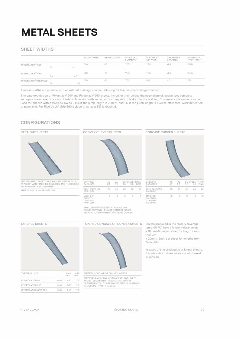
METAL SHEETS
WIDTH (MM) HEIGHT (MM) SITE ROLL / FORMING
MACHINE / CURVING
DRAINAGE / CHANNEL
MINIMUM / ROOF PITCH
RIVERCLACK® 500 500 46 YES YES YES 0,5%
RIVERCLACK® 550 550 46 YES YES YES 0,5%
RIVERCLACK® GRIP 600 600 46 YES NO NO 5%
SHEET WIDTHS
The patented design of Riverclack®500 and Riverclack®550 sheets, including their unique drainage channel, guarantees complete waterproofness, even in cases of total submersion with water, without any risk of leaks into the building. This means the system can be used for pitches with a slope as low as 0.5% if the pitch length is < 30 m, and 1% if the pitch length is ≥ 30 m, after steel work defl ection at panel end. For Riverclack® Grip 600 a slope of at least 5% is required.
Custom widths are possible with or without drainage channel, allowing for the maximum design freedom.
TAPERED CONCAVE OR CONVEX SHEETS TAPERED SHEETS Sheets produced in the factory (average temp=18 °C) have a length tolerance of:+ 10mm/-5mm per sheet for lengths less than 3m + 20mm/-5mm per sheet for lengths from 3m to 20m
In cases of site production or longer sheets, it is advisable to take into account thermal expansion.
CURVING RADIUSES
AL 0.7
AL 0.8
CU 0.6
STEEL 0.6
TITAN ZINC
SELF-CURVING RMIN (M)
25 25 30 30 20
MACHINE SMOOTH CURVING RMIN (M)
3 3 6 6 3
SMALLER RADIUSES ARE ACHIEVABLE BY CRIMP-CURVING – PLEASE CONTACT ISCOM TECHNICAL DEPARTMENT FOR MORE DETAILS.
TAPERING LIMIT MAX DIM.
MIN DIM.
RIVERCLACK® 500 (MM) 490 170
RIVERCLACK® 550 (MM) 540 170
RIVERCLACK® GRIP 600 (MM) 560 170
TAPERED CONCAVE OR CONVEX SHEETS
TAPERING AND CURVING VARIABILITY AND LIMITS ARE DETERMINED BY THE ISCOM TECHNICAL DEPARTMENT ON A CASE-BY-CASE BASIS, BASED ON THE GEOMETRY OF THE ROOF.
CURVING RADIUSES
AL 0.7
AL 0.8
CU 0.6
STEEL 0.6
TITAN ZINC
SELF-CURVING RMIN (M)
30 30 36 36 25
MACHINE SMOOTH CURVING RMIN (M)
10 8 16 16 10
CONFIGURATIONS
STRAIGHT SHEETS CONVEX CURVED SHEETS CONCAVE CURVED SHEETS
THE STANDARD SHEETS ARE AVAILABLE IN VARIOUS TYPES OF MATERIALS, THICKNESSES AND FINISHES AS REQUIRED BY THE CUSTOMER.
SHEET LENGTH: AS REQUESTED
10
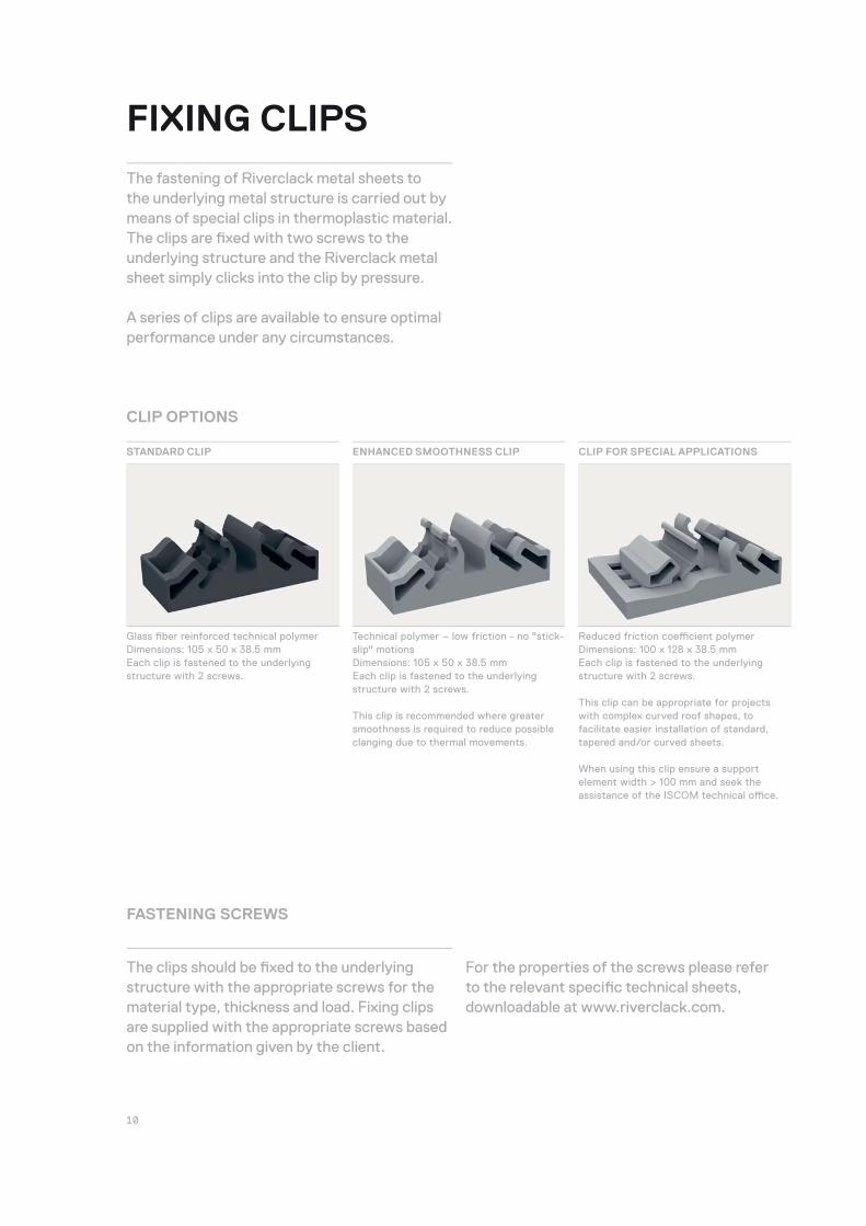
CLIP OPTIONS
STANDARD CLIP ENHANCED SMOOTHNESS CLIP CLIP FOR SPECIAL APPLICATIONS
Glass fi ber reinforced technical polymerDimensions: 105 x 50 x 38.5 mmEach clip is fastened to the underlying structure with 2 screws.
Technical polymer – low friction - no "stick-slip" motionsDimensions: 105 x 50 x 38.5 mmEach clip is fastened to the underlying structure with 2 screws.
This clip is recommended where greater smoothness is required to reduce possible clanging due to thermal movements.
Reduced friction coeffi cient polymer Dimensions: 100 x 128 x 38.5 mmEach clip is fastened to the underlying structure with 2 screws.
This clip can be appropriate for projects with complex curved roof shapes, to facilitate easier installation of standard, tapered and/or curved sheets.
When using this clip ensure a support element width > 100 mm and seek the assistance of the ISCOM technical offi ce.
FIXING CLIPS
The fastening of Riverclack metal sheets to the underlying metal structure is carried out by means of special clips in thermoplastic material. The clips are fi xed with two screws to the underlying structure and the Riverclack metal sheet simply clicks into the clip by pressure.
A series of clips are available to ensure optimal performance under any circumstances.
FASTENING SCREWS
The clips should be fi xed to the underlying structure with the appropriate screws for the material type, thickness and load. Fixing clips are supplied with the appropriate screws based on the information given by the client.
For the properties of the screws please refer to the relevant specifi c technical sheets, downloadable at www.riverclack.com.

11 RIVERCLACK SHAPING ROOFS
COLORS ANDFINISHINGS

12
STUCCO EMBOSSED ALUMINUM
Embossing is a unique stucco pattern that, besides its aesthetic qualities, helps reduce glare, an important issue with airports and buildings near highways or busy roads.
ANODIZED ALUMINUM
Aluminum Anodizing provides an aesthetically appealing matt fi nish, as well as an extra layer of protection against atmospheric agents.
NON-COATEDMATERIAL FINISHES
Depending on the metal you’re using, Riverclack® can off er a range of metal fi nishes to enhance the visual character of your building.
PRE-PATINATED COPPER
Copper is available at various stages of oxidation and patination.
PRE-OXIDIZED ZINC
Zinc, which is always pre-oxidized, off ers dramatic architectural possibilities with its ultra-modern combinations of dark and lighter shades.
13 RIVERCLACK SHAPING ROOFS
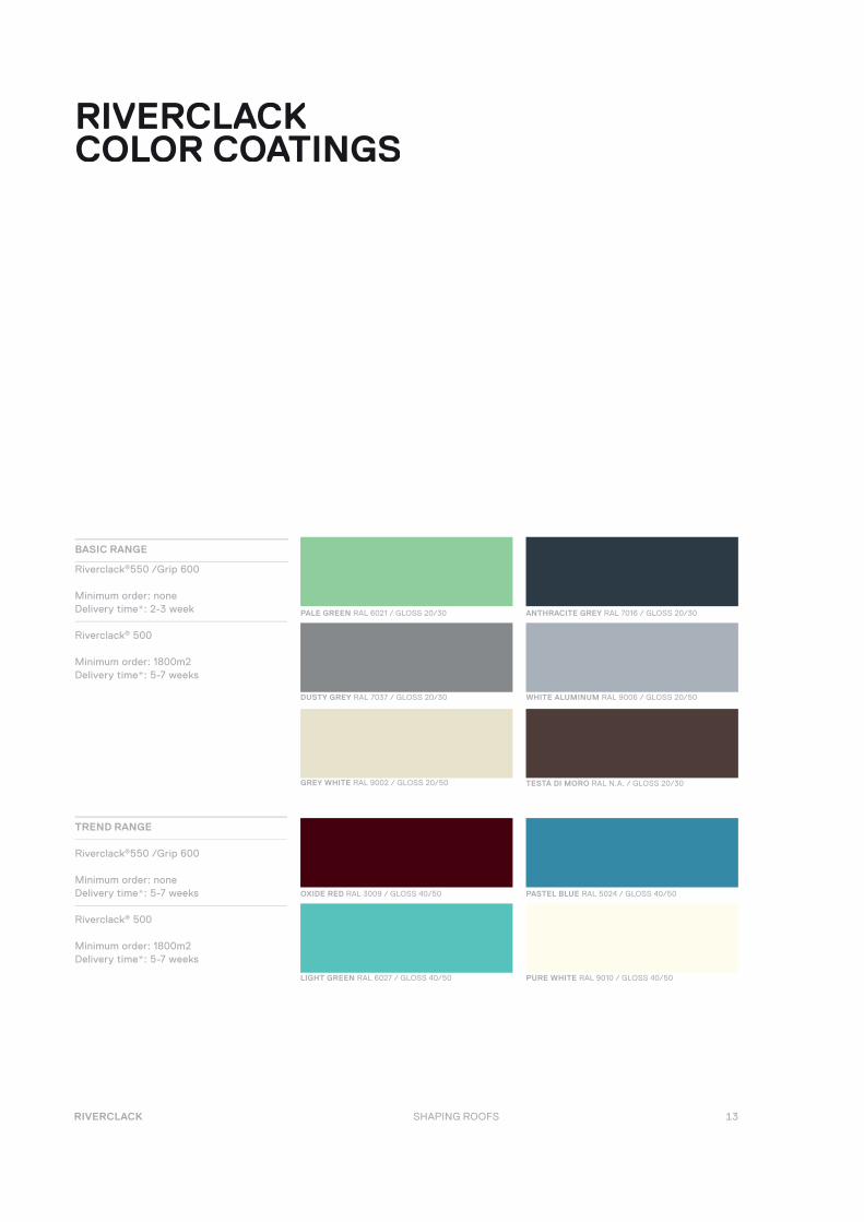
RIVERCLACK COLOR COATINGS
BASIC RANGE
ANTHRACITE GREY RAL 7016 / GLOSS 20/30
TESTA DI MORO RAL N.A. / GLOSS 20/30
PALE GREEN RAL 6021 / GLOSS 20/30
GREY WHITE RAL 9002 / GLOSS 20/50
Riverclack®550 /Grip 600
Minimum order: noneDelivery time*: 2-3 week
Riverclack® 500
Minimum order: 1800m2Delivery time*: 5-7 weeks
WHITE ALUMINUM RAL 9006 / GLOSS 20/50DUSTY GREY RAL 7037 / GLOSS 20/30
TREND RANGE
PASTEL BLUE RAL 5024 / GLOSS 40/50
Riverclack®550 /Grip 600
Minimum order: noneDelivery time*: 5-7 weeks
Riverclack® 500
Minimum order: 1800m2Delivery time*: 5-7 weeks
OXIDE RED RAL 3009 / GLOSS 40/50
PURE WHITE RAL 9010 / GLOSS 40/50LIGHT GREEN RAL 6027 / GLOSS 40/50
14
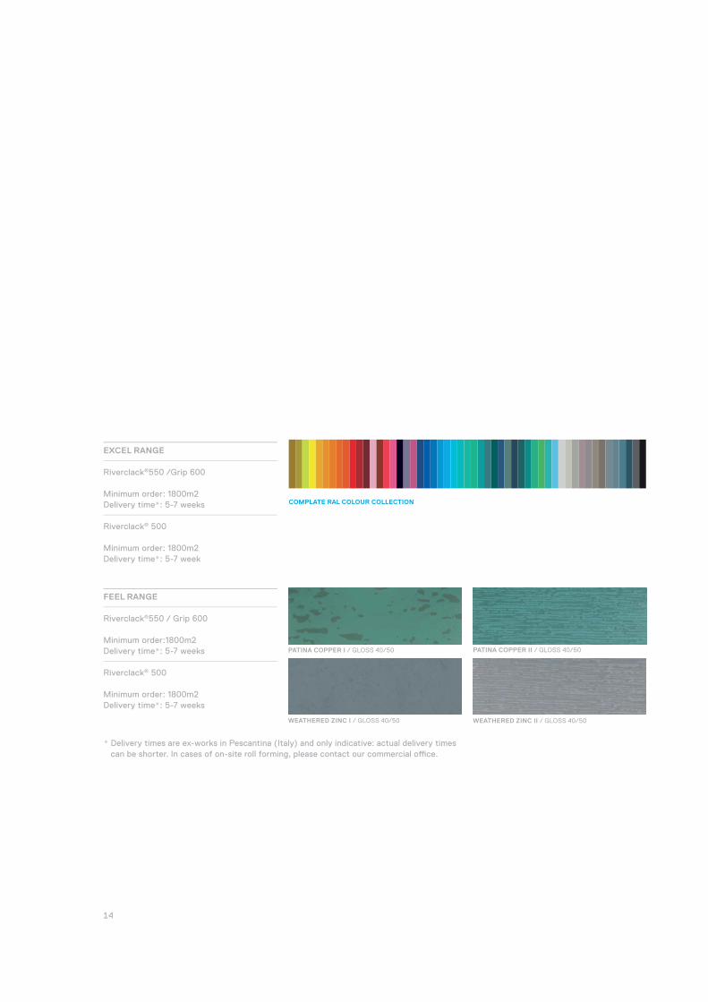
FEEL RANGE
Riverclack®550 / Grip 600
Minimum order:1800m2Delivery time*: 5-7 weeks
Riverclack® 500
Minimum order: 1800m2Delivery time*: 5-7 weeks
* Delivery times are ex-works in Pescantina (Italy) and only indicative: actual delivery times can be shorter. In cases of on-site roll forming, please contact our commercial offi ce.
PATINA COPPER I / GLOSS 40/50
WEATHERED ZINC II / GLOSS 40/50WEATHERED ZINC I / GLOSS 40/50
PATINA COPPER II / GLOSS 40/50
EXCEL RANGE
COMPLATE RAL COLOUR COLLECTION
Riverclack®550 /Grip 600
Minimum order: 1800m2Delivery time*: 5-7 weeks
Riverclack® 500
Minimum order: 1800m2Delivery time*: 5-7 week
15 RIVERCLACK SHAPING ROOFS
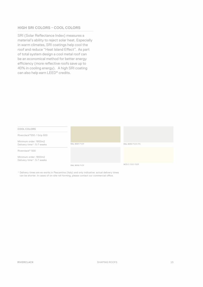
HIGH SRI COLORS - COOL COLORS
SRI (Solar Refl ectance Index) measures a material’s ability to reject solar heat. Especially in warm climates, SRI coatings help cool the roof and reduce “Heat Island Eff ect”. As part of total system design a cool metal roof can be an economical method for better energy effi ciency (more refl ective roofs save up to 40% in cooling energy). A high SRI coating can also help earn LEED® credits.
* Delivery times are ex-works in Pescantina (Italy) and only indicative: actual delivery times can be shorter. In cases of on-site roll forming, please contact our commercial offi ce.
RAL 9010 PVDF/PE
RAL 9016 PVDF NCS S 1200 Y50R
RAL 9001 PVDF
COOL COLORS
Riverclack®550 / Grip 600
Minimum order: 1800m2Delivery time*: 5-7 weeks
Riverclack® 500
Minimum order: 1800m2Delivery time*: 5-7 weeks

16
Though white or light colors remain the most refl ective, by using special pigments we can achieve relatively high SRI values even with dark colors. The below table gives SRI values for the Riverclack® Color Coatings range plus some additional high SRI color options.
COLOR REFLECTANCE EMITTANCE SRI
RAL 3009 0.249 0.825 22
RAL 5024 0.428 0.86 47
RAL 6021 0.398 0.830 42
RAL 7016 0.068 0.860 1
RAL 7037 0.222 0.820 18
RAL 9002 0.601 0.840 70
RAL 9006 0.459 0.680 44
RAL 9006 MET 0.459 0.680 44
RAL 9010 0.731 0.87 89
PATINA COPPER I 0.241 0.87 23
PATINA COPPER II 0.214 0.89 20
WEATHERED ZINC I 0.479 0.88 55
WEATHERED ZINC II 0.331 0.88 35
PYRITE GOLD / SILVER 0.544 0.86 63
PYRITE GOLD / RED 0.495 0.85 56
PYRITE GOLD / BLUE 0.413 0.88 46
REFLECTANCE MEASURES THE ABILITY OF A SURFACE TO REFLECT LIGHT OR OTHER ELECTROMAGNETIC RADIATION.
EMITTANCE MEASURES THE ABILITY OF A MATERIAL’S SURFACE TO EMIT ENERGY BY RADIATION.
THE SOLAR REFLECTANCE INDEX (SRI) IS A MEASURE OF THE CONSTRUCTED SURFACE’S ABILITY TO REFLECT SOLAR HEAT, AS SHOWN
BY A SMALL TEMPERATURE RISE. IT IS DEFINED SO THAT A STANDARD BLACK (REFLECTANCE 0.05 – EMITTANCE 0.90) IS 0 AND A STAND-
ARD WHITE (REFLECTANCE 0.80 – EMITTANCE 0.90) IS 100. TO CALCULATE THE SRI FOR A GIVEN MATERIAL, FIND ITS REFLECTANCE AND
EMITTANCE VALUES. SRI IS CALCULATED ACCORDING TO ASTM 1980.
17 RIVERCLACK SHAPING ROOFS
4
2
0
6
8
10
CHALKING
CORROSION RESISTANCE
COLOUR RETENTION
SCRATCH RESISTANCE
ABRASIVE RESISTANCE
DIRT RETENTION
CHEMICAL STABILITYREPAINTABILITY
GUARANTEE
COLOR RANGE
DURABILITY
GLOSS RETENTION
PE
PVDFPRICE PER M2
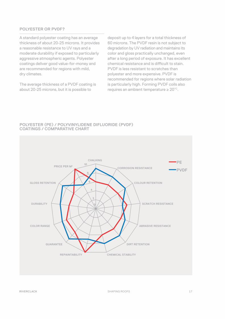
POLYESTER (PE) / POLYVINYLIDENE DIFLUORIDE (PVDF) COATINGS / COMPARATIVE CHART
POLYESTER OR PVDF?
A standard polyester coating has an average thickness of about 20-25 microns. It provides a reasonable resistance to UV rays and a moderate durability if exposed to particularly aggressive atmospheric agents. Polyester coatings deliver good value-for-money and are recommended for regions with mild, dry climates.
The average thickness of a PVDF coating is about 20-25 microns, but it is possible to
deposit up to 4 layers for a total thickness of 60 microns. The PVDF resin is not subject to degradation by UV radiation and maintains its color and gloss practically unchanged, even after a long period of exposure. It has excellent chemical resistance and is diffi cult to stain. PVDF is less resistant to scratches than polyester and more expensive. PVDF is recommended for regions where solar radiation is particularly high. Forming PVDF coils also requires an ambient temperature ≥ 20°C.
18
LOADS ANDWALKABILITY
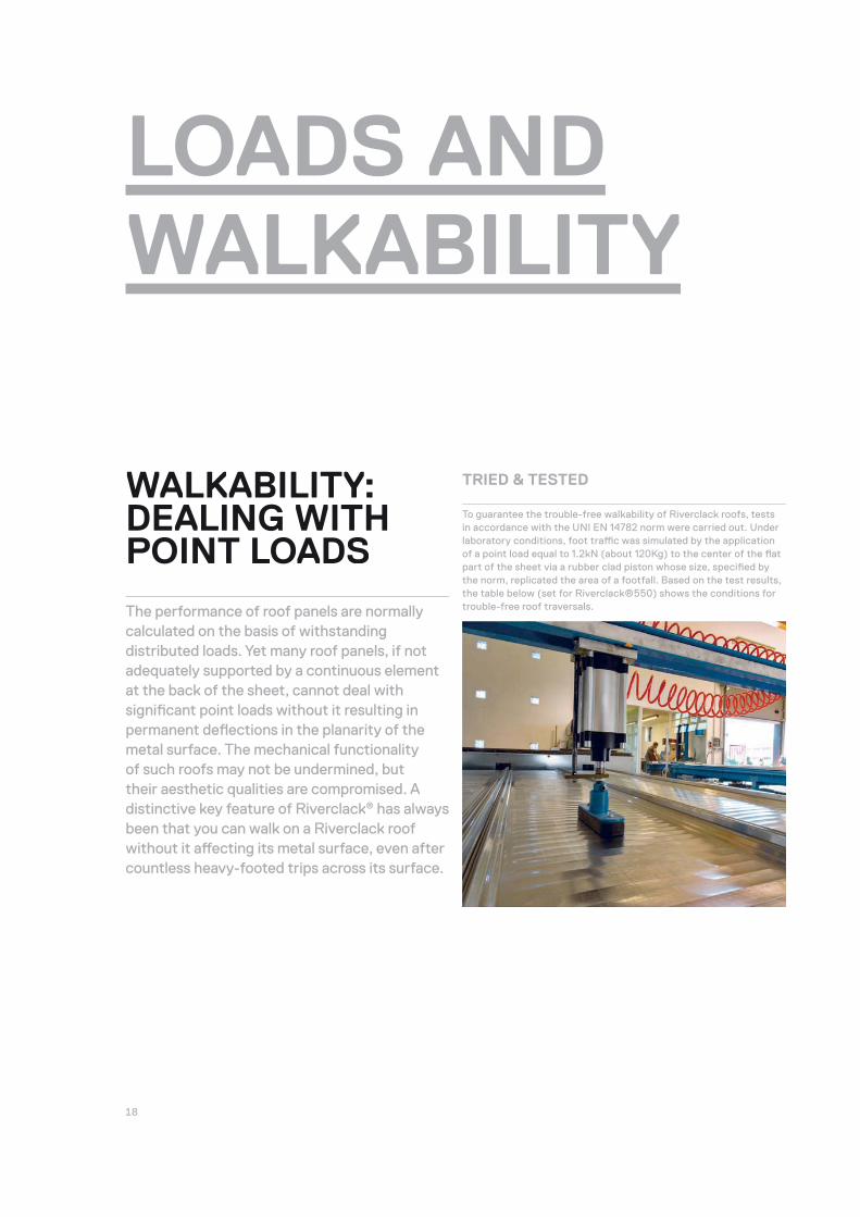
To guarantee the trouble-free walkability of Riverclack roofs, tests in accordance with the UNI EN 14782 norm were carried out. Under laboratory conditions, foot traffi c was simulated by the application of a point load equal to 1.2kN (about 120Kg) to the center of the fl at part of the sheet via a rubber clad piston whose size, specifi ed by the norm, replicated the area of a footfall. Based on the test results, the table below (set for Riverclack®550) shows the conditions for trouble-free roof traversals.
TRIED & TESTED WALKABILITY:DEALING WITH POINT LOADS
The performance of roof panels are normally calculated on the basis of withstanding distributed loads. Yet many roof panels, if not adequately supported by a continuous element at the back of the sheet, cannot deal with signifi cant point loads without it resulting in permanent defl ections in the planarity of the metal surface. The mechanical functionality of such roofs may not be undermined, but their aesthetic qualities are compromised. A distinctive key feature of Riverclack® has always been that you can walk on a Riverclack roof without it aff ecting its metal surface, even after countless heavy-footed trips across its surface.

19 RIVERCLACK SHAPING ROOFS
NOTES
It is advisable to walk on the fl at part of the sheet and not within 600mm of either of the sheet’s ends.
We recommend allowing access onto the roof to specialized personnel only, and always observing safety protocols. .
When frequent access to the roof is anticipated for maintenance/HVAC oper-ating and/or transit with heavy equipments or devices, installation of walkways is advisable to allow easier mobility and enhanced safety.
SUPPORT SPACING [CM] 100 120 140 160 180
MILL FINISH ALUMINIUM
0.7 MM
0.8 MM
1.0 MM
PER-PAINTED /
ALUMINIUM
0.7 MM
0.8 MM
1.0 MM
COPPER
0.6 MM
0.7 MM
0.8 MM
STAINLESS STEEL /
COR-TEN
0.5 MM
0.6 MM
0.7 MM
PRE-PAINTED
GALVANIZED STEEL
0.5 MM
0.6 MM
0.7 MM
TITAN ZINC
0.8 MMGIVEN ITS LOW YIELD POINT TITAN ZINC ALWAYS REQUIRES A RIGID SUPPORT UNDERNEATH
THE SHEETS AND A PROPER DESIGN. 1.0 MM
WALKABLE
WALKABLE ON THE FLAT PART
USE SPREADER BOARDS
Table 1: The table is based on a point load of approx. 120Kg
20
EVENLY-DISTRIBUTED NEGATIVE LOAD:WIND
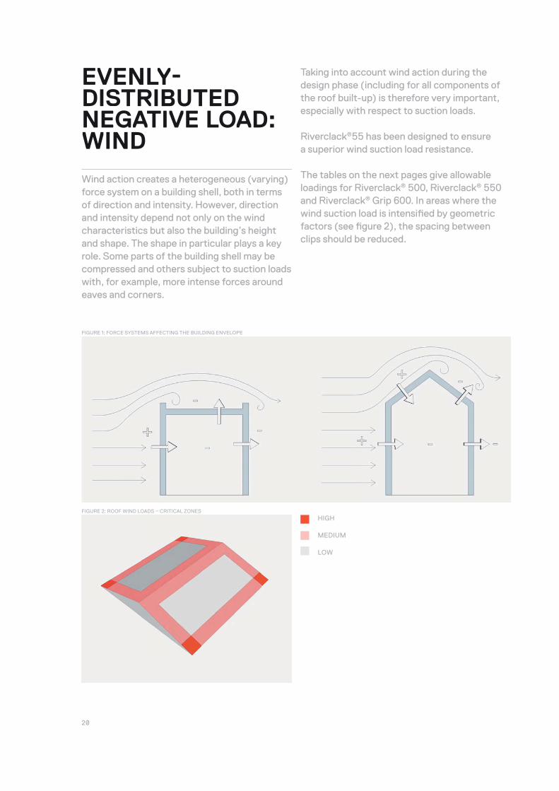
Wind action creates a heterogeneous (varying) force system on a building shell, both in terms of direction and intensity. However, direction and intensity depend not only on the wind characteristics but also the building’s height and shape. The shape in particular plays a key role. Some parts of the building shell may be compressed and others subject to suction loads with, for example, more intense forces around eaves and corners.
Taking into account wind action during the design phase (including for all components of the roof built-up) is therefore very important, especially with respect to suction loads.
Riverclack®55 has been designed to ensure a superior wind suction load resistance.
The tables on the next pages give allowable loadings for Riverclack® 500, Riverclack® 550 and Riverclack® Grip 600. In areas where the wind suction load is intensifi ed by geometric factors (see fi gure 2), the spacing between clips should be reduced.
HIGH
MEDIUM
LOW
FIGURE 1: FORCE SYSTEMS AFFECTING THE BUILDING ENVELOPE
FIGURE 2: ROOF WIND LOADS – CRITICAL ZONES

21 RIVERCLACK SHAPING ROOFS
RIVERCLACK ®500
MATERIAL THICKNESS
(MM)
LOADING (KN) / PURLIN SPAN (M)
1.0 1.2 1.4 1.6 1.8
1/90 SPAN
ULTIMATE LOAD
1/90 SPAN
ULTIMATE LOAD
1/90 SPAN
ULTIMATE LOAD
1/90 SPAN
ULTIMATE LOAD
1/90 SPAN
ULTIMATE LOAD
MILL FINISH
ALUMINIUM
0.7 - 5.75 - 4.60 - 3.60 2.69 3.10 1.67 2.45
0.8 - 5.75 - 4.60 - 3.60 2.91 3.10 2.06 2.70
1.0 - 5.75 - 4.60 - 3.60 - 3.10 2.54 2.70
PRE-PAINTED
ALUMINIUM
0.7 - 4.55 - 3.40 - 2.30 - 1.95 - 1.30
0.8 - 4.55 - 3.60 - 2.60 - 2.20 - 1.55
1.0 - 4.55 - 3.60 - 2.60 - 2.20 - 1.55
COPPER
0.6 - 5.75 - 4.60 - 6.60 - 3.10 2.62 2.45
0.7 - 5.75 - 4.60 - 3.60 - 3.10 - 2.45
0.8 - 5.75 - 4.60 - 3.60 - 3.10 - 2.45
GALVANIZED STEEL
STAINLESS STEEL
0.5 - 5.60 - 3.98 - 2.92 - 2.40 - 2.00
0.6 - 5.75 - 4.60 - 3.50 - 2.68 - 2.20
0.7 - 5.75 - 4.60 - 3.70 - 3.10 - 2.30
*TITAN ZINC
0.8 - 2.70 - 2.30 - 1.60 - 1.20 - 0.70
1.0 - 2.80 - 2.40 - 1.70 - 1.30 - 0.80
LOAD TABLES: WIND ACTION
NOTES
All loads are assumed to be applied uniformly and applied to multiple-span conditions, i.e. three spans or more.
The self-weight of sheeting has been taken into account in the above loadings.
The following load factors have been taken into account in the design capacity of the Riverclack system: defl ection =1 , ultimate load=1.5
Negative (wind) defl ection limit = span/90.
All spans are assumed to be equal to or within 15% of the largest span.
Load–span values are determined from both test and calculation.

22
RIVERCLACK ® GRIP 600
MATERIAL THICKNESS
(MM)
LOADING (KN) / PURLIN SPAN (M)
1.0 1.2 1.4 1.6 1.8
1/90 SPAN
ULTIMATE LOAD
1/90 SPAN
ULTIMATE LOAD
1/90 SPAN
ULTIMATE LOAD
1/90 SPAN
ULTIMATE LOAD
1/90 SPAN
ULTIMATE LOAD
MILL FINISH
ALUMINIUM
0.7 - 4.50 - 3.40 - 2.30 - 1.70 - 1.10
0.8 - 4.70 - 3.60 - 2.50 - 1.90 - 1.30
1.0 - 4.70 - 3.60 - 2.50 - 1.90 - 1.30
PRE-PAINTED
ALUMINIUM
0.7 - 3.40 - 2.40 - 1.30 - 0.,70 - 0.20
0.8 - 3.60 - 2.50 - 1.40 - 0.80 - 0.30
1.0 - 3.60 - 2.50 - 1.40 - 0.80 - 0.30
COPPER
0.6 - 4.00 - 3.00 - 1.90 - 1.30 - 0.70
0.7 - 4.50 - 3.40 - 2.30 - 1.70 - 0.80
0.8 - 4.70 - 3.60 - 2.50 - 1.90 - 1.30
GALVANIZED STEEL
STAINLESS STEEL
0.5 - 4.50 - 3.20 - 2.30 - 1.70 - 1.20
0.6 - 4.70 - 3.60 - 2.50 - 1.90 - 1.30
0.7 - 4.70 - 3.60 - 2.50 - 1.90 - 1.30
*TITAN ZINC
0.8 - 1.30 - 0.9 - - - - - -
1.0 - 1.60 - 1.10 - - - - - -
RIVERCLACK ®550
MATERIAL THICKNESS
(MM)
LOADING (KN) / PURLIN SPAN (M)
1.0 1.2 1.4 1.6 1.8
1/90 SPAN
ULTIMATE LOAD
1/90 SPAN
ULTIMATE LOAD
1/90 SPAN
ULTIMATE LOAD
1/90 SPAN
ULTIMATE LOAD
1/90 SPAN
ULTIMATE LOAD
MILL FINISH
ALUMINIUM
0.7 - 5.40 3.81 4.30 2.98 3.30 2.21 2.80 1.67 2.20
0.8 - 5.40 - 4.30 - 3.30 2.52 2.80 1.91 2.20
1.0 - 5.40 - 4.30 - 3.30 - 2.80 - 2.20
PRE-PAINTED
ALUMINIUM
0.7 - 4.20 - 3.10 - 2.10 - 1.65 - 1.05
0.8 - 4.20 - 3.30 - 2.30 - 1.90 - 1.30
1.0 - 4.20 - 3.30 - 2.30 - 1.90 - 1.30
COPPER
0.6 - 5.40 - 4.30 - 3.30 - 2.80 - 2.20
0.7 - 5.40 - 4.30 - 3.30 - 2.80 - 2.20
0.8 - 5.40 - 4.30 - 3.30 - 2.80 - 2.20
GALVANIZED STEEL
STAINLESS STEEL
0.5 - 5.10 - 3.70 - 2.80 - 2.30 - 1.90
0.6 - 5.30 - 4.30 - 3.10 - 2.40 - 2.00
0.7 - 5.40 - 4.30 - 3.30 - 2.80 - 2.10
*TITAN ZINC
0.8 - 2.40 - 2.00 - 1.30 - 0.80 - 0.50
1.0 - 2.50 - 2.10 - 1.40 - 0.90 - 0.60
23 RIVERCLACK SHAPING ROOFS
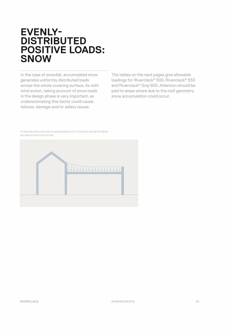
The tables on the next pages give allowable loadings for Riverclack® 500, Riverclack® 550 and Riverclack® Grip 600. Attention should be paid to areas where due to the roof geometry snow accumulation could occur.
EVENLY-DISTRIBUTED POSITIVE LOADS:SNOW
In the case of snowfall, accumulated snow generates uniformly distributed loads across the whole covering surface. As with wind action, taking account of snow loads in the design phase is very important, as underestimating this factor could cause failures, damage and/or safety issues.
ATTENTION SHOULD BE PAID TO AREAS WHERE DUE TO THE ROOF GEOMETRY SNOW
ACCUMULATION COULD OCCUR.
24
RIVERCLACK ®500
MATERIAL THICKNESS
(MM)
LOADING (KN) / PURLIN SPAN (M)
1.0 1.2 1.4 1.6 1.8
1/200 SPAN
ULTIMATE LOAD
1/200 SPAN
ULTIMATE LOAD
1/200 SPAN
ULTIMATE LOAD
1/200 SPAN
ULTIMATE LOAD
1/200 SPAN
ULTIMATE LOAD
MILL FINISH
ALUMINIUM
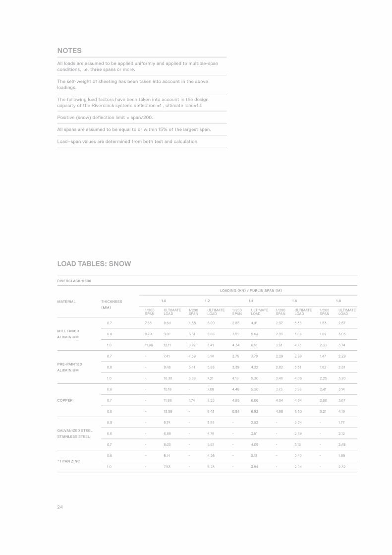
0.7 7.86 8.64 4.55 6.00 2.85 4.41 2.37 3.38 1.53 2.67
0.8 9.70 9.87 5.61 6.86 3.51 5.04 2.93 3.86 1.89 3.05
1.0 11.96 12.11 6.92 8.41 4.34 6.18 3.61 4.73 2.33 3.74
PRE-PAINTED
ALUMINIUM
0.7 - 7.41 4.39 5.14 2.75 3.78 2.29 2.89 1.47 2.29
0.8 - 8.46 5.41 5.88 3.39 4.32 2.82 3.31 1.82 2.61
1.0 - 10.38 6.68 7.21 4.18 5.30 3.48 4.06 2.25 3.20
COPPER
0.6 - 10.19 - 7.08 4.48 5.20 3.73 3.98 2.41 3.14
0.7 - 11.88 7.74 8.25 4.85 6.06 4.04 4.64 2.60 3.67
0.8 - 13.58 - 9.43 5.98 6.93 4.98 5.30 3.21 4.19
GALVANIZED STEEL
STAINLESS STEEL
0.5 - 5.74 - 3.98 - 2.93 - 2.24 - 1.77
0.6 - 6.88 - 4.78 - 3.51 - 2.69 - 2.12
0.7 - 8.03 - 5.57 - 4.09 - 3.13 - 2.48
*TITAN ZINC
0.8 - 6.14 - 4.26 - 3.13 - 2.40 - 1.89
1.0 - 7.53 - 5.23 - 3.84 - 2.94 - 2.32
NOTES
All loads are assumed to be applied uniformly and applied to multiple-span conditions, i.e. three spans or more.
The self-weight of sheeting has been taken into account in the above loadings.
The following load factors have been taken into account in the design capacity of the Riverclack system: defl ection =1 , ultimate load=1.5
Positive (snow) defl ection limit = span/200.
All spans are assumed to be equal to or within 15% of the largest span.
Load–span values are determined from both test and calculation.
LOAD TABLES: SNOW

25 RIVERCLACK SHAPING ROOFS
RIVERCLACK ® GRIP 600
MATERIAL THICKNESS
(MM)
LOADING (KN) / PURLIN SPAN (M)
1.0 1.2 1.4 1.6 1.8
1/90 SPAN
ULTIMATE LOAD
1/90 SPAN
ULTIMATE LOAD
1/90 SPAN
ULTIMATE LOAD
1/90 SPAN
ULTIMATE LOAD
1/90 SPAN
ULTIMATE LOAD
MILL FINISH
ALUMINIUM
0.7 - 6.93 4.02 4.81 2.80 3.53 1.67 2.71 1.18 2.14
0.8 - 7.90 4.60 5.48 3.20 4.03 1.91 3.08 1.34 2.44
1.0 - 9.56 5.60 6.64 3.90 4.88 2.33 3.73 1.64 2.95
PRE-PAINTED
ALUMINIUM
0.7 - 5.94 3.88 4.12 2.70 3.03 1.61 2.32 1.13 1.83
0.8 - 6.77 4.44 4.70 3.09 3.45 1.84 2.64 1.30 2.09
1.0 - 8.19 5.40 5.69 3.76 4.18 2.25 3.20 1.58 2.53
COPPER
0.6 - 8.16 - 5.67 4.09 4.16 2.44 3.19 1.72 2.52
0.7 - 9.52 - 6.61 4.77 4.86 2.85 3.72 2.00 2.94
0.8 - 10.86 - 7.54 5.45 5.54 3.26 4.24 2.29 3.35
GALVANIZED STEEL
STAINLESS STEEL
0.5 - 4.59 - 3.19 - 2.34 - 1.79 - 1.42
0.6 - 5.51 - 3.83 - 2.81 - 2.15 - 1.70
0.7 - 6.43 - 4.47 - 3.28 - 2.51 - 1.98
*TITAN ZINC
0.8 - 4.91 - 3.41 - 2.50 - 1.92 - 1.51
1.0 - 5.94 - 4.12 - 3.03 - 2.32 - 1.83
RIVERCLACK ®550
MATERIAL THICKNESS
(MM)
LOADING (KN) / PURLIN SPAN (M)
1.0 1.2 1.4 1.6 1.8
1/200 SPAN
ULTIMATE LOAD
1/200 SPAN
ULTIMATE LOAD
1/200 SPAN
ULTIMATE LOAD
1/200 SPAN
ULTIMATE LOAD
1/200 SPAN
ULTIMATE LOAD
MILL FINISH
ALUMINIUM
0.7 6.52 7.88 3.77 5.47 2.37 4.02 1.49 3.08 1.15 2.43
0.8 7.45 9.00 4.31 6.25 2.71 4.59 1.71 3.51 1.31 2.78
1.0 9.16 11.01 5.30 7.65 3.33 5.62 2.10 4.30 1.61 3.40
PRE-PAINTED
ALUMINIUM
0.7 6.29 6.75 3.64 4.69 2.29 3.44 1.44 2.64 1.11 2.08
0.8 7.19 7.71 4.16 5.36 2.62 3.93 1.65 3.01 1.27 2.38
1.0 8.84 9.44 5.12 6.56 3.22 4.82 2.03 3.69 1.56 2.91
COPPER
0.6 - 9.29 5.50 6.45 3.46 4.74 2.18 3.63 1.68 2.87
0.7 - 10.83 6.42 7.52 4.04 5.53 2.54 4.23 1.96 3.34
0.8 - 12.37 7.34 8.59 4.62 6.31 2.91 4.83 2.24 3.82
GALVANIZED STEEL
STAINLESS STEEL
0.5 - 5.23 - 3.64 - 2.67 - 2.04 - 1.62
0.6 - 6.27 - 4.36 - 3.20 - 2.45 - 1.94
0.7 - 7.31 - 5.08 - 3.73 - 2.86 - 2.26
*TITAN ZINC
0.8 - 5.59 - 3.88 - 2.85 2.06 2.18 1.58 1.73
1.0 - 6.84 - 4.75 - 3.49 2.53 2.67 1.95 2.11
*Rigid continuous support needed. Values are to be considered as Riverclack maximum workloads. Correctly design the sheets support.

26
TRANSPORT /HANDLING ANDSTORAGE
RIVERCLACK® SHEETS ARE PACKED ON THE FOLLOWING BASIS:
Sheet packs are sized according to weight to enable their transportation and handling with relevant machinery. A maximum 37 sheets per pack is allowed, provided the material is aluminium.
Two L-shaped steel profi les of the same length as the package are placed along the lower edges of the pack to avoid damage to the top sheets during handling.
Wooden framing is placed on the sheets, nailed and sealed with a steel strap, at approximately every 3 meters or less. From both ends, framing distance will not exceed 1 m.
Between the last sheet in the pack and the wood fi llet closing the frame, a piece of polystyrene foam is inserted to prevent sheet movement.
ROOF COVERING ACCESSORIES ARE PACKED AS FOLLOWS:
Support brackets are supplied in polyethylene bags and packed in cardboard boxes.
Other accessories (e.g. fl ashings, snow guards, clamps, brackets, etc) are supplied in packs or assembled on a pallet and, where required, coated with a plastic fi lm.
If necessary accessories can, like the metal sheets, be stored with wooden rings (depending on the shape and length of the accessory).
PACKING

27 RIVERCLACK SHAPING ROOFS
MATERIAL THICKNESS
(MM)
APPROXIMATE WEIGHT (KG/M2)
RIVERCLACK®500 RIVERCLACK®550 RIVERCLACK® GRIP 600
ALUMINIUM ALLOY 5754
0.7 2.70 2.63 2.41
0.8 3.09 3.00 2.76
1.0 3.86 3.75 3.44
GALVANIZED STEEL
0.6 7.59 7.39 6.77
0.7 8.84 8.62 7.90
0.8 10.13 9.86 9.03
COPPER
0.5 5.69 5.54 5.07
0.6 6.83 6.64 6.09
0.7 7.97 7.75 7.11
GALVANIZED STEEL
STAINLESS STEEL
0.5 5.59 5.44 4.99
0.6 6.71 6.53 5.98
0.7 7.83 7.62 6.98
TITAN ZINC
0.8 8.17 7.95 7.29
1.0 10.22 9.94 9.12
SHEETS WEIGHT
28
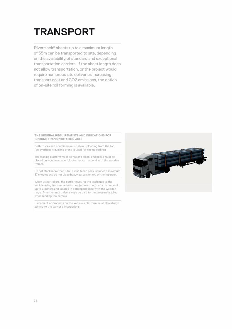
THE GENERAL REQUIREMENTS AND INDICATIONS FOR GROUND TRANSPORTATION ARE:
Both trucks and containers must allow uploading from the top (an overhead travelling crane is used for the uploading)
The loading platform must be fl at and clean, and packs must be placed on wooden spacer blocks that correspond with the wooden frames.
Do not stack more than 3 full packs (each pack includes a maximum 37 sheets) and do not place heavy parcels on top of the top pack.
When using trailers, the carrier must fi x the packages to the vehicle using transverse belts ties (at least two), at a distance of up to 3 meters and located in correspondence with the wooden rings. Attention must also always be paid to the pressure applied when binding the parcels.
Placement of products on the vehicle’s platform must also always adhere to the carrier’s instructions.
TRANSPORT
Riverclack® sheets up to a maximum length of 35m can be transported to site, depending on the availability of standard and exceptional transportation carriers. If the sheet length does not allow transportation, or the project would require numerous site deliveries increasing transport cost and CO2 emissions, the option of on-site roll forming is available.
29 RIVERCLACK SHAPING ROOFS
!
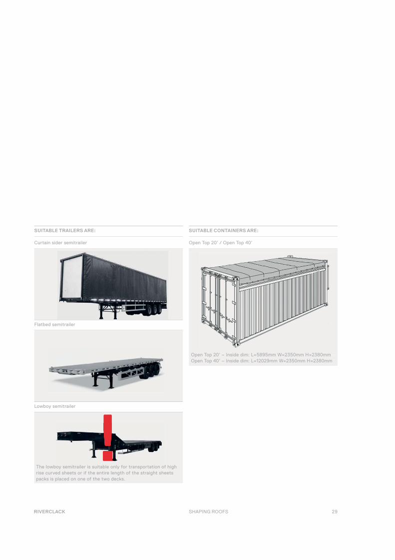
SUITABLE TRAILERS ARE:
Curtain sider semitrailer
SUITABLE CONTAINERS ARE:
Open Top 20’ / Open Top 40’
!
Flatbed semitrailer
Lowboy semitrailer
Open Top 20’ – Inside dim: L=5895mm W=2350mm H=2380mmOpen Top 40’ – Inside dim: L=12029mm W=2350mm H=2380mm
The lowboy semitrailer is suitable only for transportation of high rise curved sheets or if the entire length of the straight sheets packs is placed on one of the two decks.

30
SOLLEVAMENTO
HANDLING Uploading, downloading and handling of packs must always be done one pack at a time. Depending on the sheet length and the number of sheets per pack, a forklift, crane or lifting beam can be used.
For both a truck crane and a lifting beam, the pack must be slung a maximum of every 3-3.5 metres, and overhang at the ends must not exceed 1.5m.
Nylon woven (or other synthetic fi bre) belts with a minimum width of 60 mm and minimum length of 4 meters are recommended.
Before laying the profi led sheet packs on the roof, ensure the load bearing capacity of the roof substructure is suffi cient. Then secure the packs to prevent any sliding.
In general, for a sheet length less than 6m a forklift or truck crane with belts is suitable. For sheets longer than 6m, a lifting beam is recommended.
SHEET LENGTH < 6M
SHEET LENGTH < 6M
SHEET LENGTH > 6M
1.5M
3.5M
1.5M
31 RIVERCLACK SHAPING ROOFS
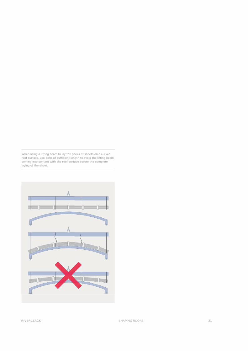
When using a lifting beam to lay the packs of sheets on a curved roof surface, use belts of suffi cient length to avoid the lifting beam coming into contact with the roof surface before the complete laying of the sheet.
32
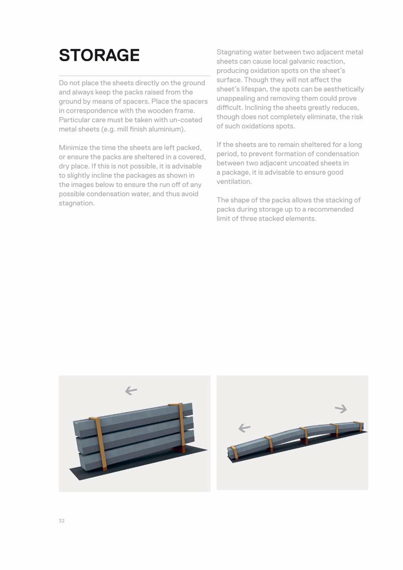
Stagnating water between two adjacent metal sheets can cause local galvanic reaction, producing oxidation spots on the sheet’s surface. Though they will not aff ect the sheet’s lifespan, the spots can be aesthetically unappealing and removing them could prove diffi cult. Inclining the sheets greatly reduces, though does not completely eliminate, the risk of such oxidations spots.
If the sheets are to remain sheltered for a long period, to prevent formation of condensation between two adjacent uncoated sheets in a package, it is advisable to ensure good ventilation.
The shape of the packs allows the stacking of packs during storage up to a recommended limit of three stacked elements.
STORAGE
Do not place the sheets directly on the ground and always keep the packs raised from the ground by means of spacers. Place the spacers in correspondence with the wooden frame. Particular care must be taken with un-coated metal sheets (e.g. mill fi nish aluminium).
Minimize the time the sheets are left packed, or ensure the packs are sheltered in a covered, dry place. If this is not possible, it is advisable to slightly incline the packages as shown in the images below to ensure the run off of any possible condensation water, and thus avoid stagnation.
←
←←

33 RIVERCLACK SHAPING ROOFS
Riverclack Roof System sheets can be installed on the following support elements: linear (metal purlin, wood purlin) and continuous (plywood or wood planks, foamglas).
The type of materials and geometric characteristics of the supporting structure can signifi cantly aff ect the roofi ng system’s performance. It is therefore necessary to design and dimension the structures so as to support the predicted stresses, both in terms of positive loads (e.g. snow loads) and negative loads (e.g. wind suction). Depending on the type of support used, its compatibility with the clip’s screws should be verifi ed, where not already listed in the Riverclack® clips’ screws specifi cations.
For installation on concrete slabs, clips should never be installed directly onto the concrete surface, but instead by the interposition of linear support elements, such as a metal or wood purlin system, so as to ensure proper installation planarity and roof performance. require numerous site deliveries increasing transport cost and CO2 emissions, the option of on-site roll forming is available.
SUPPORT ELEMENTS
INSTALLATION
METAL PURLIN
The minimum width of the purlin to guarantee the correct installation of the Riverclack® clips is 50 mm.
The metal support elements are in general cold shaped profi les (C, U, Z, Ω sections) in galvanized steel.
For the highest wind load resistance requirements, use of section Ω metal purlins with a thickness greater than 1.5 mm is recommended.
MIN. 50 MM
MIN. 50 MM
34
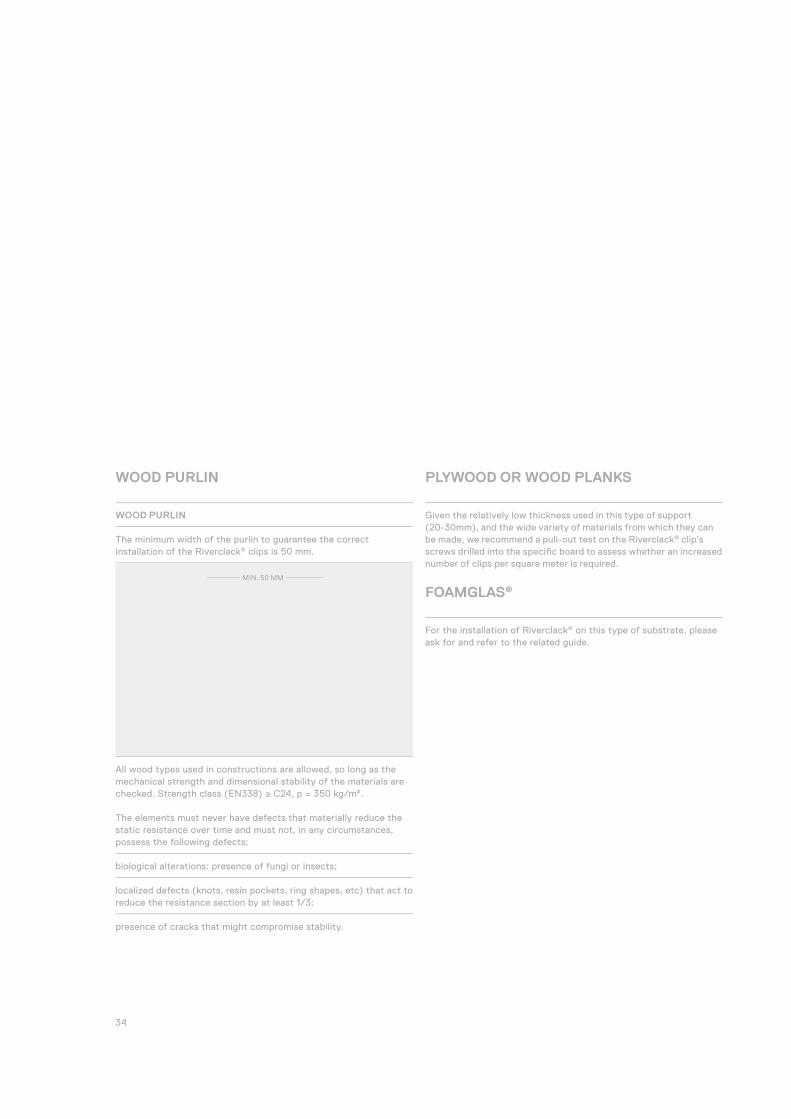
WOOD PURLIN
The minimum width of the purlin to guarantee the correct installation of the Riverclack® clips is 50 mm.
All wood types used in constructions are allowed, so long as the mechanical strength and dimensional stability of the materials are checked. Strength class (EN338) ≥ C24, p = 350 kg/m³.
The elements must never have defects that materially reduce the static resistance over time and must not, in any circumstances, possess the following defects:
biological alterations: presence of fungi or insects;
localized defects (knots, resin pockets, ring shapes, etc) that act to reduce the resistance section by at least 1/3;
presence of cracks that might compromise stability.
PLYWOOD OR WOOD PLANKS
Given the relatively low thickness used in this type of support (20-30mm), and the wide variety of materials from which they can be made, we recommend a pull-out test on the Riverclack® clip’s screws drilled into the specifi c board to assess whether an increased number of clips per square meter is required.
FOAMGLAS®
For the installation of Riverclack® on this type of substrate, please ask for and refer to the related guide.
WOOD PURLIN
MIN. 50 MM

35 RIVERCLACK SHAPING ROOFS
Riverclack® secret fi x standing seam metal roof system is a high engineering product, as the locking method relies on the engage-ment with the clips of the metal sheet laps. To ensure its proper functioning, possible fl uctuations in level, alignment and slope of the supports on which the clips are fi xed must be included as part of the consideration of admitted tolerances.
IF TOLERANCES IN THE SUPPORT STRUCTURE ARE NOT RESPECTED THIS CAN HAVE THE FOLLOWING SIGNIFICANT CONSEQUENCES:
cause a reduction in the load capacity (whether negative or positive)
compromise the system’s watertightness
cause water stagnation
compromise the thermal expansion and contraction capacity.
To ensure proper functioning of the secret fi x metal roof system, tolerance recommendations should be considered at an early stage of the structure design process.
Where tolerances have not been respected, it may be possible to make adjustments on site through the relative positioning of spacers, below clips or purlins in order to restore the proper installation plans.
TOLERANCESPURLIN LEVELS
PURLIN SLOPE
ROOF PLAN
ROOF PLAN
± 1°FIXING CLIP
+ L/150 OR 10MM- L/300 OR 5MM
LL

36
INSTALLATIONPROCEDURE The installation of the fi rst sheet is extremely important, since it serves as a reference for the installation of all subsequent sheets. The impact of mistakes and inaccuracies made in this initial phase can become more pronounced as the installation of successive ele-ments of the roof progresses.
Install the fi rst run of Riverclack® clips on the support elements by using a plumb line. If the sheets are not extremely long, the sheet itself can be used to get the alignment. In case of use of templates for the clips’ positioning the clip alignment admitted tolerance is +-1mm.
The procedure for securing the Riverclack sheets onto the relevant clips is a 6-step process (please also refer to the corresponding images):
Between steps 3 and 4 do not forget to include a fi xed point at the correct location as specifi ed by the project!
Ensure that the profi le is correctly located in the clip and push at location shown.
Secure the clips to the support element using the appropriate fi xings. The correct location of the clips is determined by the sheet itself.
Place the overlap side of the next sheet into the clip repeating step 1.
Repeat step 2, treading gently on the top of the profi le to ensure the sheet is fully locked into the clip.
Push carefully on the top until the sheet locks into the clip (you should feel a “click”).
Once the sheet is completely secured to the fi rst run of clips, insert by hand the second run of clips to the free side of the sheet (gutter side for Riverclack®500 and Riverclack®550, the side that is overlapped for Riverclack® GRIP 600).
1.
6.
2. 3.
4. 5.
37 RIVERCLACK SHAPING ROOFS
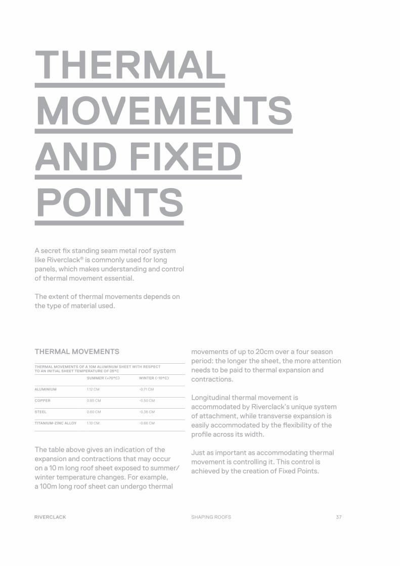
THERMALMOVEMENTSAND FIXEDPOINTSA secret fi x standing seam metal roof system like Riverclack® is commonly used for long panels, which makes understanding and control of thermal movement essential.
The extent of thermal movements depends on the type of material used.
THERMAL MOVEMENTS OF A 10M ALUMINUM SHEET WITH RESPECT TO AN INITIAL SHEET TEMPERATURE OF 25°C
SUMMER (+70°C) WINTER (-10°C)
ALUMINIUM 1.12 CM -0.71 CM
COPPER 0.85 CM -0.50 CM
STEEL 0.60 CM -0.36 CM
TITANIUM-ZINC ALLOY 1.10 CM -0.66 CM
movements of up to 20cm over a four season period: the longer the sheet, the more attention needs to be paid to thermal expansion and contractions.
Longitudinal thermal movement is accommodated by Riverclack’s unique system of attachment, while transverse expansion is easily accommodated by the fl exibility of the profi le across its width.
Just as important as accommodating thermal movement is controlling it. This control is achieved by the creation of Fixed Points.
The table above gives an indication of the expansion and contractions that may occur on a 10 m long roof sheet exposed to summer/winter temperature changes. For example, a 100m long roof sheet can undergo thermal
THERMAL MOVEMENTS
38
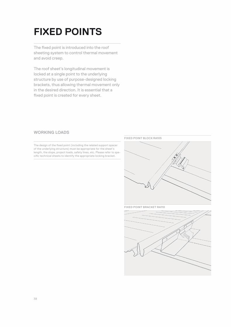
The design of the fi xed point (including the related support spacer of the underlying structure) must be appropriate for the sheet’s length, the slope, project loads, safety lines, etc. Please refer to spe-cifi c technical sheets to identify the appropriate locking bracket.
FIXED POINTS
The fi xed point is introduced into the roof sheeting system to control thermal movement and avoid creep. The roof sheet’s longitudinal movement is locked at a single point to the underlying structure by use of purpose-designed locking brackets, thus allowing thermal movement only in the desired direction. It is essential that a fi xed point is created for every sheet.
WORKING LOADSFIXED POINT BLOCK RA105
FIXED POINT BRACKET RA110
39 RIVERCLACK SHAPING ROOFS
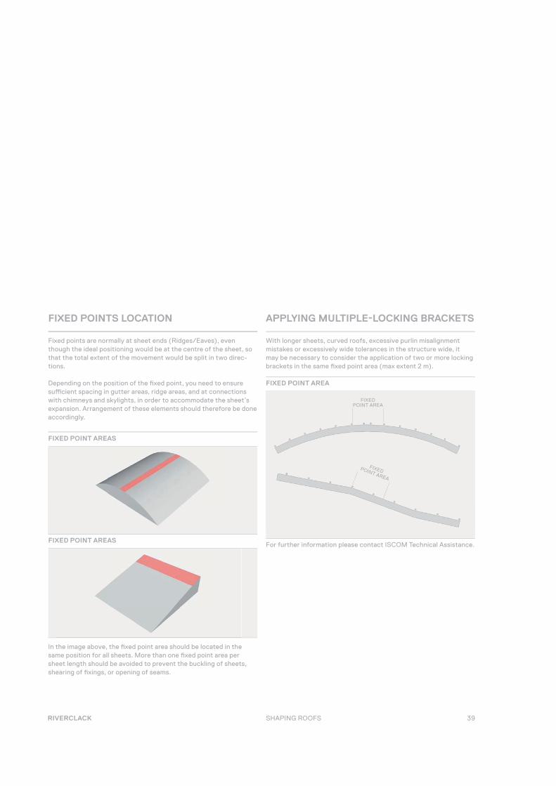
With longer sheets, curved roofs, excessive purlin misalignment mistakes or excessively wide tolerances in the structure wide, it may be necessary to consider the application of two or more locking brackets in the same fi xed point area (max extent 2 m).
For further information please contact ISCOM Technical Assistance.
Fixed points are normally at sheet ends (Ridges/Eaves), even though the ideal positioning would be at the centre of the sheet, so that the total extent of the movement would be split in two direc-tions.
Depending on the position of the fi xed point, you need to ensure suffi cient spacing in gutter areas, ridge areas, and at connections with chimneys and skylights, in order to accommodate the sheet’s expansion. Arrangement of these elements should therefore be done accordingly.
In the image above, the fi xed point area should be located in the same position for all sheets. More than one fi xed point area per sheet length should be avoided to prevent the buckling of sheets, shearing of fi xings, or opening of seams.
FIXED POINTS LOCATION APPLYING MULTIPLE-LOCKING BRACKETS
FIXED POINT AREAS
FIXED POINT AREAS
FIXED POINT AREA
FIXED POINT AREA
FIXED POINT AREA
40
ON-SITEPRODUCTION
Where panels are too long to be produced at our factories and transported to the construction site, we provide on-site forming and curving. This is also an option when the size of the project would otherwise require numerous site deliveries.
The following indications are intended to complement local construction site arrangement plans, relevant machinery and equipment instructions, and to be used in compliance with current regulations and other requirements related to operational instructions, security, safety and risk assessment.
Before the mobile profi ling unit (MPU) arrives on site, the roof contractor is responsible for ensuring that the site is prepared as described in this section so the work can be carried out appropriately on site.
41 RIVERCLACK SHAPING ROOFS
FEATURES OF THE MOBILE PROFILING UNITS (MPU)AND CURVINGMACHINES (CV)
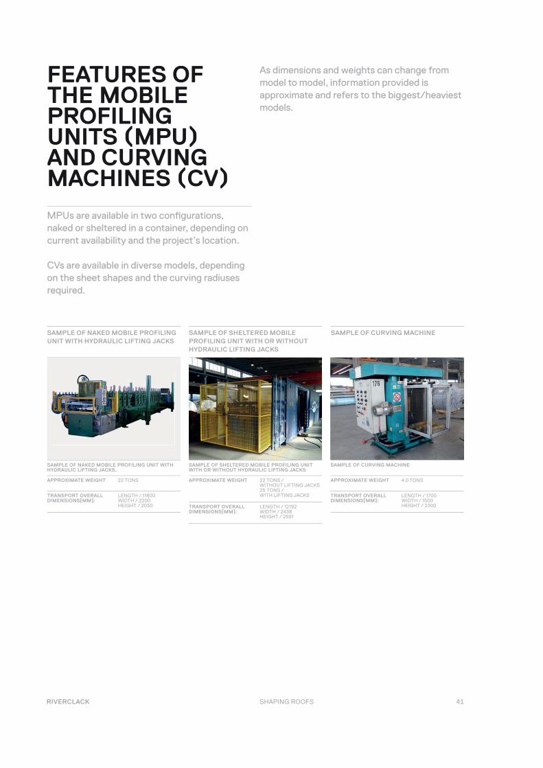
MPUs are available in two confi gurations, naked or sheltered in a container, depending on current availability and the project’s location.
CVs are available in diverse models, depending on the sheet shapes and the curving radiuses required.
As dimensions and weights can change from model to model, information provided is approximate and refers to the biggest/heaviest models.
SAMPLE OF NAKED MOBILE PROFILING UNIT WITH HYDRAULIC LIFTING JACKS
SAMPLE OF CURVING MACHINE
SAMPLE OF NAKED MOBILE PROFILING UNIT WITH HYDRAULIC LIFTING JACKS.
APPROXIMATE WEIGHT 22 TONS
TRANSPORT OVERALL DIMENSIONS[MM]:
LENGTH / 11800WIDTH / 2200HEIGHT / 2050
SAMPLE OF SHELTERED MOBILE PROFILING UNIT WITH OR WITHOUT HYDRAULIC LIFTING JACKS
APPROXIMATE WEIGHT 22 TONS / WITHOUT LIFTING JACKS 25 TONS /WITH LIFTING JACKS
TRANSPORT OVERALL DIMENSIONS[MM]:
LENGTH / 12192WIDTH / 2438HEIGHT / 2591
SAMPLE OF CURVING MACHINE
APPROXIMATE WEIGHT 4.0 TONS
TRANSPORT OVERALL DIMENSIONS[MM]:
LENGTH / 1700WIDTH / 1500HEIGHT / 2300
SAMPLE OF SHELTERED MOBILE PROFILING UNIT WITH OR WITHOUT HYDRAULIC LIFTING JACKS
42
ON-SITE PROFILING
GROUND PREPARATION
Ensure that an area that is fl at, compact and free from stagnant wa-ter is made available to support the weight of the profi ling machine. It should be assumed the weight will be distributed over 4 support points 200 mm when loading and unloading using the hydraulic jacks (i.e. for the naked MPU).
Access to the site must be verifi ed and confi rmed by the roof contractor. Unrestricted access of transport means that a total weight of approximately 27 tons can be accommodated.
ON-SITE UMP LOADING AND UNLOADING
Depending on the type of MPU employed, the roof contractor will need to provide the following for loading and unloading operations:
Nothing for a naked MPU transported by a fl atbed semitrailer.
A Crane and, if necessary, suitable Cables for a naked MPU not transported by a fl atbed semitrailer.
Nothing for a sheltered MPU with hydraulic Jacks.
A Crane and, if necessary, suitable Cables for a sheltered MPU with-out Hydraulic Jacks.
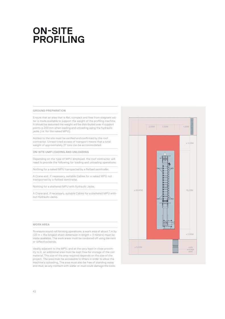
WORK AREA
To ensure sound roll forming operations, a work area of about 7 m by (20 m + the longest sheet dimension in length + 3 meters) must be made available. The work areas must be cordoned off using barriers or refl ective bands.
Ideally adjacent to the MPU, and at the very least in close proxim-ity to it, an additional area must be kept free for storage of the coil material. The size of the area required depends on the size of the project. The area must be accessible to lifters in order to allow the machine’s uploading. The area must also be free of standing water and mud, as any contact with water or mud could damage the coils.
2,00M 3,50M 1,00M
≥ 3,00M coilsstorage
area
≥ 20,00M
≥ 3,00M
≥ 2,00M
15,00M
43 RIVERCLACK SHAPING ROOFS
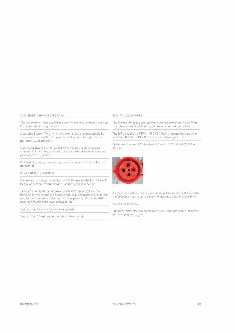
ELECTRICAL SUPPLY
The availability of the appropriate electrical power on the building site must be confi rmed before commencement of operations.
The MPU requires a 30kW – 380V 50 Hz 3-phase power source or minimum 100kW – 380V 50 Hz 3-phase power generator.
Powerboard as per IEC standard, socket IEC EN 60309-2 63 Amp 3P + E.
COIL HANDLING AND STORAGE
The maximum weight of a coil is about 4 tons for aluminum coils and 5 tons for steel or copper coils.
A suitable Stacker Truck with operator must be made available by the roof contractor for lifting and handling coils throughout the period of site production.
Coils must always be kept raised from the ground by means of spacers. Furthermore, to avoid oxidation they must be covered and protected from humidity.
Coil handling and correct storage are the responsibility of the roof contractor.
STAFF REQUIREMENTS
An operator will be provided by ISCOM to operate the MPU. He will be the only person authorized to use the profi ling machine. The roof contractor must provide suffi cient manpower for the handling of the Riverclack sheets produced. The number of workers required will depend on the length of the panels and the material used, based on the following calculation:
1 person per 7 meters for aluminum panels
1 person per 4.5 meters for copper or steel panels
A power feed cable of 50m is provided by Iscom. The roof contractor is responsible for ensuring adequate electrical supply to the MPU.
WASTE DISPOSAL
The roof contractor is responsible for ensuring the correct disposal of packaging and waste.
44
ONSITE CURVING
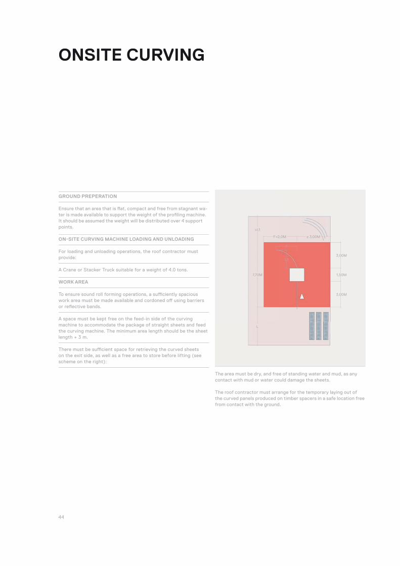
GROUND PREPERATION
Ensure that an area that is fl at, compact and free from stagnant wa-ter is made available to support the weight of the profi ling machine. It should be assumed the weight will be distributed over 4 support points.
ON-SITE CURVING MACHINE LOADING AND UNLOADING
For loading and unloading operations, the roof contractor must provide:
A Crane or Stacker Truck suitable for a weight of 4.0 tons.
WORK AREA
To ensure sound roll forming operations, a suffi ciently spacious work area must be made available and cordoned off using barriers or refl ective bands.
A space must be kept free on the feed-in side of the curving machine to accommodate the package of straight sheets and feed the curving machine. The minimum area length should be the sheet length + 3 m.
There must be suffi cient space for retrieving the curved sheets on the exit side, as well as a free area to store before lifting (see scheme on the right):
The area must be dry, and free of standing water and mud, as any contact with mud or water could damage the sheets.
The roof contractor must arrange for the temporary laying out of the curved panels produced on timber spacers in a safe location free from contact with the ground.
≥ 3,00MF+2,0M
F
L1
>L1
L
7,70M
3,00M
3,00M
1,50M

45 RIVERCLACK SHAPING ROOFS
STAFF REQUIREMENTS
An operator will be provided by ISCOM to operate the Curving Machine. He will be the only person authorized to use the Curving Machine. The roof contractor must provide suffi cient manpower for the unpacking of the straight sheets, as well as for the handling, receipt, storage and possible repacking of the curved sheets. The number of workers required depends on the length of the panels and the mate-rial used, based on the following calculation:
The roof contractor must provide suffi cient manpower for the handling of the Riverclack sheets produced. The number of workers required will depend on the length of the panels and the material used, based on the following calculation:
1 person per 7 meters for aluminum panels
1 person per 4.5 meters for copper or steel panels
ELECTRICAL SUPPLY
The availability of the appropriate electrical power on the building site must be confi rmed before commencement of operations.The Curving Machine requires a 10kW – 380V 50Hz 3-phase power source.
Powerboard as per IEC standard, socket IEC EN 60309-2 32 Amp 3P + E.
A power feed cable of 20m is provided by Iscom. The roof contractor is responsible for ensuring adequate electrical supply to the Curving Machine.
WASTE DISPOSAL
The roof contractor is responsible for ensuring the correct disposal of packaging and waste.
46
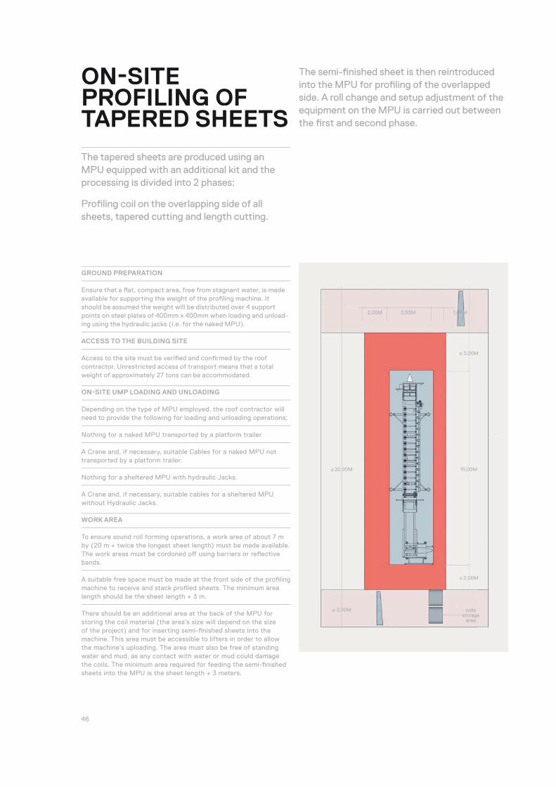
GROUND PREPARATION
Ensure that a fl at, compact area, free from stagnant water, is made available for supporting the weight of the profi ling machine. It should be assumed the weight will be distributed over 4 support points on steel plates of 400mm x 400mm when loading and unload-ing using the hydraulic jacks (i.e. for the naked MPU).
ACCESS TO THE BUILDING SITE
Access to the site must be verifi ed and confi rmed by the roof contractor. Unrestricted access of transport means that a total weight of approximately 27 tons can be accommodated.
ON-SITE UMP LOADING AND UNLOADING
Depending on the type of MPU employed, the roof contractor will need to provide the following for loading and unloading operations;
Nothing for a naked MPU transported by a platform trailer
A Crane and, if necessary, suitable Cables for a naked MPU not transported by a platform trailer.
Nothing for a sheltered MPU with hydraulic Jacks.
A Crane and, if necessary, suitable cables for a sheltered MPU without Hydraulic Jacks.
WORK AREA
To ensure sound roll forming operations, a work area of about 7 m by (20 m + twice the longest sheet length) must be made available. The work areas must be cordoned off using barriers or refl ective bands.
A suitable free space must be made at the front side of the profi ling machine to receive and stack profi led sheets. The minimum area length should be the sheet length + 3 m.
There should be an additional area at the back of the MPU for storing the coil material (the area’s size will depend on the size of the project) and for inserting semi-fi nished sheets into the machine. This area must be accessible to lifters in order to allow the machine’s uploading. The area must also be free of standing water and mud, as any contact with water or mud could damage the coils. The minimum area required for feeding the semi-fi nished sheets into the MPU is the sheet length + 3 meters.
ON-SITE PROFILING OF TAPERED SHEETS
The tapered sheets are produced using an MPU equipped with an additional kit and the processing is divided into 2 phases:
Profi ling coil on the overlapping side of all sheets, tapered cutting and length cutting.
The semi-fi nished sheet is then reintroduced into the MPU for profi ling of the overlapped side. A roll change and setup adjustment of the equipment on the MPU is carried out between the fi rst and second phase.
2,00M 3,50M 1,00M
≥ 3,00M coilsstorage
area
≥ 20,00M
≥ 3,00M
≥ 2,00M
15,00M

47 RIVERCLACK SHAPING ROOFS
COIL HANDLING AND STORAGE
The maximum weight of a coil is about 4 tons for aluminum coils and 5 tons for steel or copper coils.
A suitable Stacker Truck with operator must be made available by the roof contractor for lifting and handling coils throughout the period of site production.
Coils must always be kept raised from the ground by means of spacers. Furthermore, to avoid oxidation they must be covered and protected from humidity.
Coil handling and correct storage are the responsibility of the roof contractor.
SEMI-FINISHED SHEETS TEMPORARY PLACING
Do not place the semi-fi nished sheets directly on the ground, and al-ways keep them raised from the ground by means of spacers. Place the spacers in correspondence with the wooden frame. Particular care must be taken with un-coated metal sheets (e.g. mill fi nish aluminium).
STAFF REQUIREMENTS
An operator will be provided by ISCOM to operate the MPU. He will be the only person authorized to use the profi ling machine. The roof contractor must provide suffi cient manpower for the handling of the Riverclack sheets produced. The number of workers required will depend on the length of the panels and the material used, based on the following calculation:
1 person per 7 meters for aluminum panels
1 person per 4.5 meters for copper or steel panels
ELECTRICAL SUPPLY
The availability of the appropriate electrical power on the building site must be confi rmed before commencement of operations.
The MPU requires a 30kW – 380V 50 Hz 3-phase power source or minimum 100kW – 380V 50 Hz 3-phase power generator.
Powerboard as per IEC standard, socket IEC EN 60309-2 63 Amp 3P + E.
A power feed cable of 50m is provided by Iscom. The roof contractor is responsible for ensuring adequate electrical supply to the MPU.
WASTE DISPOSAL
The roof contractor is responsible for ensuring the correct disposal of packaging and waste.
48
OPERATIONANDMAINTENANCE
In order to ensure the safety of operators, all maintenance and inspection operations must be carried out in full compliance with safety regulations.

49 RIVERCLACK SHAPING ROOFS
Inspections must be carried out at regular intervals. The initial inspection must coincide with the building inspection or completion of the work. Subsequent inspections must occur at least annually, though it is preferable to carry out two annual inspections, for example in spring and autumn.
During the fi rst inspection following roof completion, it must be verifi ed that foreign materials or work scraps that could cause corrosion or damage to the covering system have not been left on the roof. Such corrosion can also harm the aesthetic appearance of the covering, impede the proper fl ow of rainwater, and/or produce an accumulation of unwanted substances (dust, sand, leaves, etc).
Subsequent inspections should consist of a verifi cation of the general conditions of the covering — state of conservation of the elements, ridges, fl ashings, gutters, fi xture resistance and possible seals — and also verify the effi ciency of rainwater drainage and technological systems.
CLEANINGIt is important to clean away any accumulation of dirt on the covering formed by debris that rainwater cannot remove. Special attention must be paid to low slope roofs, since they are more prone to collecting debris. Proper cleaning of the covering also avoids formation of water stagnation.
The cleaning must be carried out by hand with a soft broom (hard brooms are strongly discouraged), or using a pressure cleaner at a maximum pressure of 50 bar.
In the case of the formation of mold, the roof must be treated with appropriate anti-molds, and the area then washed using warm water.
Graffi ti or other unwanted marks must be removed using special solvents.
50
MAINTENANCEMAINTENANCE IS NECESSARY IN THE EVENT OF: A DEPOSIT OF MATERIALS OF ANY NATURE
(leaves, clusters of dust, etc) particularly in gutters or drains, as such debris can obstruct the regular outfl ow of rainwater.
In such cases, fi rst remove foreign material and then wash with running water until the surface of the components are visible in order to confi rm the integrity of the base material.
Where roofs are installed in industrial areas where using running water alone is not enough, neutral soaps may also be used.
AREAS WITH SIGNS OF CORROSION ON GALVANIZED PRE-PAINTED SHEETS
In such cases, follow these 5 steps:
Remove the layer of paint in the area surrounding the point of corrosion;
Remove all corroded elements
Smooth the relevant area evenly and apply a coat of anticorrosive primer
Once the anticorrosive primer is dry, apply a new primer for the paint phase
Once this second primer coating is dry, apply the paint.
WEAK ACCESSORY FIXINGS
All weak fasteners must be tightened using special instruments, paying particular attention to safety lines and snow guards.
DEFECTS IN THE SEALING OF ACCESSORIES OR COMPLEMENTARY ELEMENTS
In such cases, fasteners must be integrated or, depending on the extent of the defect, completely replaced.

51 RIVERCLACK SHAPING ROOFS
54
ISCOM SPA VIA BELVEDERE, 7837026 PESCANTINAITALY
[email protected] +39 045 773 21 77F +39 045 773 29 70


