Download - ROGERS GEOTECHNICAL SERVICES LTD

ROGERS GEOTECHNICAL SERVICES LTD
The Ground Investigation Specialists
OFFICES 1&2 BARNCLIFFE BUSINESS PARK NEAR BANK
SHELLEY HUDDERSFIELD
HD8 8LU
Tel 0843 50 666 87 Fax 0843 51 599 30

REPORT ON A GEOTECHNICAL INVESTIGATION
at
5 FAIRFIELD MILL, QUEENS STREET SOUTH, HUDDERSFIELD, WEST YORKSHIRE.
for
BATES and Co.
CONSULTANTS: FARRAR BAMFORTH ASSOCIATES Ltd.
Report No J2701/14/E April 2014

CONTENTS
Page 1. SYNOPSIS 1 2. INTRODUCTION 1 3. LIMITATIONS 2 4. FIELDWORKS 2 4.1 Windowless Sample Boreholes 2 4.2 Dynamic Probes 2 5. GEOLOGY 3 6. STRATA CONDITIONS 3 6.1 Made Ground 3 6.2 Silty Clay 4 6.3 Groundwater 4 7. INSITU TESTING 4 8. LABORATORY TESTING - GEOTECHNICAL 5 8.1 Moisture Content Determinations 5 8.2 Index Property Tests 5 8.3 Mass Loss on Ignition 5 8.4 Sulphate Content and pH Values 5 9. DISCUSSION OF GROUND CONDITIONS – GEOTECHNICAL 6 9.1 Piled Foundations 6 9.2 Retaining Walls 6 9.3 General 7 9.4 Effect of Sulphates 7 10. REFERENCES 7 APPENDIX 1 – SITE PLAN APPENDIX 2 – WINDOWLESS SAMPLE BOREHOLE RECORDS APPENDIX 3 – DYNAMIC PROBE RECORDS APPENDIX 4 – LABORATORY TESTING – GEOTECHNICAL
Rogers Geotechnical Services Ltd J2701/14/E Phone 0843 50 666 87
1
REPORT ON A GEOTECHNICAL INVESTIGATION
at
FAIRFIELD MILL, QUEENS STREET SOUTH, HUDDERSFIELD, WEST YORKSHIRE.
for
BATES and Co.
CONSULTANTS: FARRAR BAMFORTH ASSOCIATES Ltd.
Report No J2701/14/E April 2014 1. SYNOPSIS
This is a complex structural alteration to the existing building which is to include the erection of a new steel framed extension, constructed on a piled foundation. In addition, the works will include infilling a triangular semi basement yard after the construction of a new retaining structure immediately adjacent to the existing walls. This investigation has demonstrated that made ground was revealed to the full depth of the two boreholes situated on the higher ground, which attained a depth of 4m. The borehole situated at the lower level, within the triangular semi basement area, revealed made ground to 2.7m depth, whereupon grey and orangey brown mottled silty clay was proved to 4m below surface. In view of the complex nature of this development the discussion of ground conditions should be carefully considered.
2. INTRODUCTION
It is understood that the development of this building is to include the construction of steel framed extension, founded upon piles through the made ground. Additionally, new retaining walls are to be constructed adjacent to the existing walls within the triangular basement yard, which will then be infilled. Accordingly, a site investigation has been undertaken in accordance with the instruction from the client. This work was required in order to determine the nature of the underlying soils, to assess their engineering properties and to assist in the design of safe and economical foundations for the proposed extension and retaining walls.

Rogers Geotechnical Services Ltd J2701/14/E Phone 0843 50 666 87
2
3. LIMITATIONS The recommendations made and opinions expressed in this report are based on the ground conditions revealed by the site works, together with an assessment of the site and of the laboratory test results. Whilst opinions may be expressed relating to sub-soil conditions in parts of the site not investigated, for example between borehole positions, these are for guidance only and no liability can be accepted for their accuracy. This report has been prepared in accordance with our understanding of current best practice. However, new information or legislation, or changes to best practice may necessitate revision of the report after the date of issue.
4. FIELDWORKS
The fieldworks were undertaken on the 20th March 2014 and included the following: • Three windowless sample boreholes, two on the higher ground and one
within the triangular basement yard, about 3.5m below the other two. • Three dynamic probes adjacent to the borehole positions.
It was initially intended to sink two boreholes within the basement yard, but access difficulties meant that this was not possible within the time available. The investigatory locations are shown on the site plan which is presented in Appendix 1 to this report.
4.1 Windowless Sample Boreholes
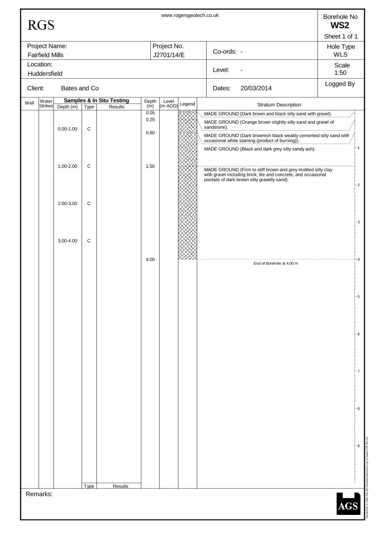
These boreholes were sunk using a drive-in windowless sampler. The cores were undertaken in 1m lengths and reduced in diameter from 90mm for the first 1m through 80mm, 70mm and 60mm for subsequent 1m increments. The recovered cores were sealed and returned to the laboratory for logging and subsequent testing. The soils were described in general accordance with BS5930: 1999, as amended in 2007, and full descriptions are given on the window sample records which are presented in Appendix 2. Also included on these records are the core diameters and percentages of core recovered.
4.2 Dynamic Probes
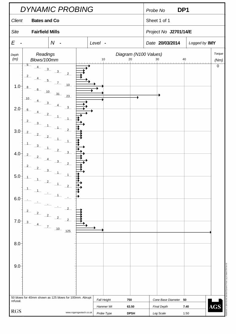
Dynamic penetration tests were undertaken adjacent to the windowless sample borehole in accordance with the procedure given in BS1377: 1990: Part 9, using the super heavy penetrometer (DPSH). This probe consists of a 63.5kg mass falling through 750mm onto an anvil, which drives a 50mm diameter cone into the ground. The number of blows required to drive the cone through successive 100mm increments are recorded as the N100 values. The results of the dynamic penetration

Rogers Geotechnical Services Ltd J2701/14/E Phone 0843 50 666 87
3
tests are tabulated and presented as bar charts of N100 values versus depth in Appendix 3.
5. GEOLOGY
The available published geological data for the site has been examined and the following table presents the anticipated geology.
Table 1: Geological Data for the Site
Strata Type Parent Unit1
Strata Name2 Description2
Superficial Geology
Glaciofluvial Deposits - Sand and gravel, locally with lenses of silt, clay or
peat. [Generic description].
Solid Geology
Pennine Lower Coal Measures
Soft Bed Flags
The Soft Bed Flags are generally fine-grained, thinly-bedded and cross-bedded to flaggy sandstone interbedded with mudstone
6. STRATA CONDITIONS
During the investigation the geological succession has been shown to include the following: Table 2: Generalised strata profile
Depth (m below ground
level, to underside of layer)
Strata type Positions layer was
revealed in
Groundwater strikes
(m below ground level)
2.7 – 4.0 Made Ground All None 4.0 Silty CLAY WS3 None
‘+’ Denotes that the strata extended below the termination depth of the investigated positions, thus the extent of the deposit is only proven to the depths indicated. This profile is considered in more detail below.
6.1 Made Ground
From the upper part of the site, in WS 1 and 2, the made ground initially comprised a nominal thickness of dark brown and black silty sand over orangey brown slightly silty sand and gravel. This was observed to cap predominantly dark brown and black silty sandy gravel, including concrete, brick and masonry fragments. Within this horizon seams or pockets of ash and zones with sandstone gravel were noted at various depths. At these locations the fill was revealed to the full depth investigated, with the boreholes being terminated at 4m below ground level (0.5m below basement yard floor level).
1 Source: Geology of Britain Viewer [online resource from www.bgs.ac.uk] 2 Source: British Geological Survey (NERC) Lexicon of Named Rock Units [online resource from www.bgs.ac.uk]

Rogers Geotechnical Services Ltd J2701/14/E Phone 0843 50 666 87
4
WS 3 was undertaken in the basement yard, some 3.5m below the surrounding ground level and the made ground was proved to 2.7m depth. At this location the fill initially consisted of dark brown and brown silty clay with gravel including concrete and brick fragments, becoming brown and orange brown mottled silty clay and gravel between 2.4m and 2.7m depth. A 300mm layer of remnant topsoil was then encountered.
6.2 Silty Clay
On penetrating the remnant topsoil revealed in WS3, very soft to soft grey and orangey brown mottled silty clay with occasional sandstone gravel was revealed and proved to a depth of 4.0m below the basement yard ground level. It is considered that this deposit is associated with the Glaciofluvial Deposits, which is known to underlie this site.
6.3 Groundwater
It should be noted that groundwater levels are subject to seasonal variation or changes on local drainage conditions. However, at this site no groundwater strikes were observed during the drilling operations.
7. INSITU TESTING
Dynamic penetration tests were conducted adjacent to the windowless sample boreholes. On the active side of the retaining wall (DP 1 and 2), the results were reasonable, but variable to a depth of about 2.0m, Within this zone there were a number of obstructions which gave isolated high results. From about 2m depth the penetration resistance reduced to between zero and 3 blows/100mm depths of 7.2m in DP1, where abrupt refusal was encountered, and 6.5m in DP2. From this depth the penetration resistance gradually increased until refusal at 10.3m depth. On the basis of all of the information obtained from this investigation it is thought that the made ground will be revealed to about 6m below surface, with glaciofluvial deposits then being encountered, with bedrock at about 10m depth. It is considered that DP 1 met refusal on an obstruction within the glaciofluvial deposits. At the location of DP3 the resistance to penetration varied between 4 and 10 blows/100mm in the upper 1.0m. From this depth the results reduced to between zero and 2 blows/100mm to 4.0m depth, whereupon the resistance to penetration was noted to be variable, ranging between 3 and 10 blows/100mm. A rapid increase in resistance was then noted, with effective refusal being noted at 7.8m depth. It is considered that this represents the depth to bedrock, and is at the same level as that noted in DP2.

Rogers Geotechnical Services Ltd J2701/14/E Phone 0843 50 666 87
5
8. LABORATORY TESTING - GEOTECHNICAL A programme of laboratory testing has been undertaken in accordance with BS1377 unless stated otherwise and the results are presented in Appendix 4. Each type of test is briefly summarised below and the results have been used to assist in the formulation of the discussion of ground conditions.
8.1 Moisture Content Determinations (Part 2 : 1990 : 3)
Selected samples of the made ground and underlying glaciofluvial deposits have been subjected to moisture content determinations and the results yielded natural water contents ranging between 18% and 31%.
8.2 Index Property Tests (Part 2 : 1990 : 4, 5 and 6.5) The liquid and plastic limits of the cohesive soils have been determined and the results yielded liquid limits within the range of 34% and 43% in association with plastic limits of 17% and 23%, and thus with respect to the recorded moisture content, consistency indices of between 0.6 and 1.1. These results demonstrate that these cohesive soils may be generally classified as clay of low to intermediate plasticity. In addition, the NHBC classification3 indicates that the clay revealed at this site possesses, in the most onerous case, a medium volume change potential.
8.3 Mass Loss on Ignition (Part 3 : 1990 : 4) Three samples taken from the made ground have been subject to mass loss on ignition in order to evaluate their organic content. The results of this work indicated that the ash revealed in WS 2 yielded a mass loss on ignition of 8%, indicating that some combustible material remains. The samples containing topsoil or remnant topsoil possesses mass loss of 6% and 10%.
8.4 Sulphate Content and pH Values
The sulphate contents and pH values of sample obtained from the made ground have been determined and the results are presented on the chemical test results sheet. Soluble sulphate contents ranging between 0.07g/l and 0.70g/l were recorded in association with pH values of between 8.1 and 8.8.
3 NHBC Standards, Chapter 4.2, Building near trees, Table 1 – Volume change potential

Rogers Geotechnical Services Ltd J2701/14/E Phone 0843 50 666 87
6
9. DISCUSSION OF GROUND CONDITIONS – GEOTECHNICAL
This development is to include the construction of a new steel framed extension, constructed on a piled foundation. In addition, the works will include infilling a triangular semi basement yard after the construction of a new retaining structure immediately adjacent to the existing walls.
9.1 Piled Foundations The results of this investigation indicate that the made ground and glaciofluvial deposits are present in a generally weak insitu condition, thus it is understood that the extension is to be supported on a piled foundation. In view of the proximity of the existing buildings it is considered that driven pre-cast piling techniques would not be appropriate in this instance. Therefore, attention should be directed to bored piles installed with ‘down the hole hammer’ (DTH) techniques (e.g. Odex), drilled piles or similar. In order to formulate a suitable design it is recommended that the advice of specialist piling contractors be sought. It may be assumed that the bedrock comprises extremely weak sandstone, thus a rock socketed pile constructed to achieve at least 3m penetration into the sandstone could be adopted. As the triangular basement yard is to be up-filled, settlement of the weak underlying soils are inevitable. Consequently, the piles should be designed assuming that negative skin friction will occur within the made ground and Glaciofluvial deposits. In view of the relatively weak near surface soils it will be necessary to construct a working platform for the piling rig and any other plant required during the works. Such a design should be undertaken in accordance with the procedures given in the BRE publication entitled Working platforms for tracked plant.
9.2 Retaining Walls
The retaining walls are to be constructed adjacent to the existing walls within the triangular basement yard prior to up-filling to ground level. It should be appreciated that settlement of the retaining structure is likely due to the presence of the weak made ground and glaciofluvial deposits. Consequently, it is recommended that the retaining structures are also supported on piles socketed into the underlying sandstone. The effective stress parameters to be employed in the design will depend upon the nature of the in-fill material. When the source of this material is established, the effective stress parameters may be evaluated.

Rogers Geotechnical Services Ltd J2701/14/E Phone 0843 50 666 87
7
9.3 General
The stability of any excavations faces cannot be guaranteed thus temporary support may become necessary. Under no circumstances should operatives be allowed to enter unsupported excavations.
9.4 Effect of Sulphates
In view of the nature of the underlying soils it is considered that the design sulphate class be assessed with reference to Table C24, which is provided in BRE Special Digest 1, Concrete in aggressive ground: Part C. On the basis of this table and considering the soluble sulphate contents recorded, it can be shown that well compacted buried concrete should be designed in accordance with Class DS-2 requirements. Assuming static groundwater at this site, the table also indicates that the aggressive chemical environment for concrete (ACEC) classification is AC-1s.
In order to evaluate the design chemical (DC) class for the buried concrete at this site reference should be made to Table D15, which can be found in Part D, Specifying concrete for general cast-in-situ use, of BRE Special Digest 1. From this table it may be shown that for an intended working life of at least 50 years the concrete design class DC-1 is required.
10. REFERENCES
• British Geological Survey (NERC) (2014), BGS, Keyworth. Geology of Britain Viewer: (http://maps.bgs.ac.uk/geologyviewer_google/googleviewer.html) Lexicon of Named Rock Units: (http://www.bgs.ac.uk/lexicon/)
• British Standards Institution (1990) BS1377: British standard methods of test for soils for civil engineering purposes, B.S.I., London.
• British Standards Institution (1999) BS5930: Code of practice for site
investigations, incorporating amendment no.1 (2007), B.S.I., London. • British Standards Institution (2004) BS EN ISO 14688: Geotechnical
investigation and testing – Identification and classification of soil, incorporating corrigendum no.1 (2007), B.S.I., London.
4 Table C2, Aggressive Chemical Environment for Concrete (ACEC) classification for brownfield sites 5 Table D1, Selection of the DC Class and the number of APMs for concrete elements where the hydraulic gradient due to groundwater is 5 or less: for general in-situ use of concrete.

Rogers Geotechnical Services Ltd J2701/14/E Phone 0843 50 666 87
8
• Building Research Establishment (BRE) Special Digest 1 (2005), Third Edition: Concrete in aggressive ground, BRE Press, Gamston.
Part C: Assessing the aggressive chemical environment. Part D: Specifying concrete for general cast-in-situ use.
For and on behalf of Rogers Geotechnical Services Ltd, S.P. Rogers CEng, CGeol, MICE, MCIHT, FGS Technical Director

Rogers Geotechnical Services Ltd J2701/14/E Phone 0843 50 666 87
9
APPENDIX 1
SITE PLAN

BH2
TP1WS2
WS1
Title: Investigation Location Plan
Rogers Geotechnical Services Ltd J2701/14/E
Job No:Site Name:Fairfield Mill, HuddersfieldBates and Co
BH1WS3
Bates and Co.
Rogers Geotechnical Services Ltd J2701/14/E Phone 0843 50 666 87
10
APPENDIX 2
WINDOWLESS SAMPLE BOREHOLE RECORDS

Legend(m) (m AOD) Stratum Description
Project Name:
Location:
Client: Dates:
Level:
Co-ords:Project No.
Remarks:
Well WaterStrikes Depth (m)
Depth Level
Borehole No
Hole Type
Scale
Logged By
Fairfield Mills
Huddersfield
Bates and Co
Type
Type
Samples & In Situ TestingResults
Results
J2701/14/E
www.rogersgeotech.co.uk
-
-
20/03/2014
WS1
WLS
Hol
eBA
SE
3.1
(Bld
426
.48)
Sta
ndar
d B
oreh
ole
Log
v2 d
ated
27t
h N
ov 0
3
0.00-1.00
1.00-2.00
2.00-3.00
3.00-4.00
C
C
C
C
0.06
0.30
0.90
1.30
2.20
3.00
4.00
MADE GROUND (Dark brown and black silty sand with gravel).
MADE GROUND (Orange brown slightly silty sand and gravel ofsandstone).
MADE GROUND (medium dense dark brown and black silty sand andgravel with concrete, masonary and brick fragments).
MADE GROUND (Black silty and sandy ash).
MADE GROUND (Brown, dark brown and occasionally black mottledslightly clayey sand and gravel witth occasional pockets ofash).
MADE GROUND Dark brownish black organic sandy clay with gravel).
MADE GROUND (Brown, dark brown and occasionally black mottledslightly clayey sand and gravel witth occasional pockets ofash).
End of Borehole at 4.00 m
1
2
3
4
5
6
7
8
9
1:50
Sheet 1 of 1
Legend(m) (m AOD) Stratum Description
Project Name:
Location:
Client: Dates:
Level:
Co-ords:Project No.
Remarks:
Well WaterStrikes Depth (m)
Depth Level
Borehole No
Hole Type
Scale
Logged By
Fairfield Mills
Huddersfield
Bates and Co
Type
Type
Samples & In Situ TestingResults
Results
J2701/14/E
www.rogersgeotech.co.uk
-
-
20/03/2014
WS2
WLS
Hol
eBA
SE
3.1
(Bld
426
.48)
Sta
ndar
d B
oreh
ole
Log
v2 d
ated
27t
h N
ov 0
3
0.00-1.00
1.00-2.00
2.00-3.00
3.00-4.00
C
C
C
C
0.050.25
0.60
1.50
4.00
MADE GROUND (Dark brown and black silty sand with gravel).
MADE GROUND (Orange brown slightly silty sand and gravel ofsandstone).
MADE GROUND (Dark brownish black weakly cemented silty sand withoccasional white staining (product of burning)).
MADE GROUND (Black and dark grey silty sandy ash).
MADE GROUND (Firm to stiff brown and grey mottled silty claywith gravel including brick, tile and concrete, and occasionalpockets of dark brown silty gravelly sand).
End of Borehole at 4.00 m
1
2
3
4
5
6
7
8
9
1:50
Sheet 1 of 1

Legend(m) (m AOD) Stratum Description
Project Name:
Location:
Client: Dates:
Level:
Co-ords:Project No.
Remarks:
Well WaterStrikes Depth (m)
Depth Level
Borehole No
Hole Type
Scale
Logged By
Fairfield Mills
Huddersfield
Bates and Co
Type
Type
Samples & In Situ TestingResults
Results
J2701/14/E
www.rogersgeotech.co.uk
-
-
20/03/2014
WS3
WLS
Hol
eBA
SE
3.1
(Bld
426
.48)
Sta
ndar
d B
oreh
ole
Log
v2 d
ated
27t
h N
ov 0
3
0.00-1.00
1.00-2.00
2.00-3.00
3.00-4.00
C
C
C
C
1.60
2.40
2.70
4.00
MADE GROUND (Dark brown and brown silty clay with gravelincluding concrete and brick).
MADE GROUND (Brown and orang-brown mottled silty clay withscattered gravel including concrete fragments).
MADE GROUND (Dark brown organic silty clay with scattered gravel(remnant topsoil)).
Soft grey and orange brown mottled silty CLAY with occasionalsandstone gravel.
End of Borehole at 4.00 m
1
2
3
4
5
6
7
8
9
1:50
Sheet 1 of 1

Rogers Geotechnical Services Ltd J2701/14/E Phone 0843 50 666 87
11
APPENDIX 3
DYNAMIC PROBE RECORDS
1:50
Sheet 1 of 1
DYNAMIC PROBING Probe No
Client
Site
E N Level
Project No
Date
Depth(m)
ReadingsBlows/100mm
Torque
(Nm)Diagram (N100 Values)
Probe Type
Hammer Wt
Fall Height Cone Base Diameter
Final Depth
Log Scale
Logged by
50 blows for 40mm shown as 125 blows for 100mm. Abruptrefusal.
-
Bates and Co
Fairfield Mills
-
www.rogersgeotech.co.uk
-
63.50
750
DPSH
20/03/2014
J2701/14/E
DP1
50
7.40
IMY
Hol
eBA
SE
3.1
(Bld
426
.48)
Sta
ndar
d D
ynam
ic P
robe
Log
v2
date
d 27
th N
ov 0
3
54
33
22
45
710
86
1031
2310
43
43
64
21
12
31
12
22
21
11
31
23
22
43
22
23
11
11
21
21
1-
1-
--
--
22
22
22
34
710
125
0
1.0
2.0
3.0
4.0
5.0
6.0
7.0
8.0
9.0
10 20 30 40

88
1313
1813
97
66
911
927
2114
50
0
1.0
2.0
3.0
4.0
5.0
6.0
7.0
8.0
9.0
10 20 30 40
1:50
Sheet 1 of 1
DYNAMIC PROBING Probe No
Client
Site
E N Level
Project No
Date
Depth(m)
ReadingsBlows/100mm
Torque
(Nm)Diagram (N100 Values)
Probe Type
Hammer Wt
Fall Height Cone Base Diameter
Final Depth
Log Scale
Logged by
Abrupt Refusal.
-
Bates and Co
Fairfield Mills
-
www.rogersgeotech.co.uk
-
63.50
750
DPSH
20/03/2014
J2701/14/E
DP2
50
10.20
IMY
Hol
eBA
SE
3.1
(Bld
426
.48)
Sta
ndar
d D
ynam
ic P
robe
Log
v2
date
d 27
th N
ov 0
3
810
3331
83
25
51
11
110
3225
157
3-
1-
22
513
96
34
31
12
-1
11
12
44
53
21
1-
12
12
22
21
32
22
23
34
34
44
54
67
610
1215
1210
87
77
77
88

1:50
Sheet 1 of 1
DYNAMIC PROBING Probe No
Client
Site
E N Level
Project No
Date
Depth(m)
ReadingsBlows/100mm
Torque
(Nm)Diagram (N100 Values)
Probe Type
Hammer Wt
Fall Height Cone Base Diameter
Final Depth
Log Scale
Logged by-
Bates and Co
Fairfield Mills
-
www.rogersgeotech.co.uk
-
63.50
750
DPSH
20/03/2014
J2701/14/E
DP3
50
6.70
IMY
Hol
eBA
SE
3.1
(Bld
426
.48)
Sta
ndar
d D
ynam
ic P
robe
Log
v2
date
d 27
th N
ov 0
3
04
57
107
64
3-
34
11
11
-1
--
--
-1
-1
11
1-
--
--
22
11
15
57
53
33
55
74
45
105
810
99
65
44
413
1430
2631
0
1.0
2.0
3.0
4.0
5.0
6.0
7.0
8.0
9.0
10 20 30 40

Rogers Geotechnical Services Ltd J2701/14/E Phone 0843 50 666 87
12
APPENDIX 4
LABORATORY TESTING – GEOTECHNICAL

Determination of Moisture Content, Liquid and Plastic Limits
Rogers Geotechnical Services Ltd Offices 1&2 Barncliffe Business Park, Near Bank, Shelley Huddersfield HD8 8LUwww.rogersgeotech.co.uk
08/04/2014
J2701/14/EJob No:
Bates and Co
1Tel : 0843 5066687 Fax : 0843 5159930
Fairfield Mill
Site:
Sheet:Date:
Client:
(m)
BS. 1377 : PART 2 : 1990 : 3.2, 4 and 5
borehole/ trial pit no.
sample no. sample depth
(%)
moisture content
sample prep.
remarks:
2.80
WS3 C4 3.30
X
X
27
XA
WS3 A 43C2 1.80
test method (liquid limit):sample preparation:
23
38
17
0
34
11
B - washed on 0.425mm sieve
C - air dried
E - not known
X - cone penetrometer (test 4.3)
Y - one point cone penetrometer (test 4.4)
Z - Casagrande apparatus (test 4.5)
A - as recieved D - oven dried (50°C)
plastic limit
(%) (%) (%)
test method
fraction >0.425mm
liquid limit
Made Ground (Brownish grey silty clay)19
description/remarks
(%)
Made Ground (brown sandy gravelly CLAY
plasticity index
17
Made Groind (Brown / grey mottled silty clay)
20Mad Ground (Dark brown clay with gravel)
20
21
0 18
40
notes: moisture content undertaken in accordance with BS1377 : Part 2 : 1990 : 3.2 (unless specified)
Grey/brown mottled silty CLAY.
WS2 C3
WS1 C4
WS1
3.60 20
18
31
27
A
A
C3 2.60 X 30

17 17
(ω P)
N.H.B.C Class
Liquid Limit
(ω ) (ω L)
(%)
(Ι C)(Ι L)
Liquidity/ Consistency
(Ι P')
WS3 3.30 27 38
Depth Plastic Limit
18
18
Casagrande Class
Job No:
Site:
J2701/14/EClient:
Modified (ω )
(ω ')
Sheet:
Fax : 0843 5159930
Fairfield Mill
Location
(%)(%)
Rogers Geotechnical Services Ltd Offices 1&2 Barncliffe Business Park, Near Bank, Shelley Huddersfield HD8 8LUwww.rogersgeotech.co.uk
Tel : 0843 5066687
(m)
Moisture Content
(%)
Retained by 425μm
(%)
Plasticity Index
(Ι P)
(%)(%)
Bates and Co
2
(%) (%)
Modified (Ι P)
(%)
Date:
08/04/2014
Interpretation of Moisture Content, Liquid and Plastic Limits
26 L0.1 0.9 C123034WS1 2.60
WS1 3.60 20 2040 1921
LOW
23
1.1 C I LOW-0.1019
31 43WS3 1.80
0.520 0 0.627 20
1620 4022
I
C I0.6
C MEDIUM
0.4 LOW
ML or MLOMI or MIO
MH or MHO
MV or MVO
ME or MEO
CL
CI
CH
CV
CE
0
10
20
30
40
50
60
70
0 10 20 30 40 50 60 70 80 90 100 110 120
Plas
ticity
Inde
x %
(ΙP)
Liquid Limit % (ωL)Liquid Limit % (ωL)

Determination of Mass Loss on Ignition
Rogers Geotechnical Services Ltd Offices 1&2 Barncliffe Business Park, Near Bank, Shelley Huddersfield HD8 8LUwww.rogersgeotech.co.uk
Tel : 0843 5066687 08/04/2014
J2701/14/EJob No:
Bates and Co
3Fax : 0843 5159930
Fairfield Mill
Site:
Sheet:Date:
Client:
BS. 1377 : PART 3 : 1990 : 4
borehole/ trial pit no.
sample no. sample depth
fraction >2mm
mass loss on ignition
(m) (%) (%)
WS2 C2 1.10 35
WS3 Made Ground (Brown/grey mottled organic silty clay with gravel)
WS1
Made Ground (Black and dark grey silty sandy ash)
C4 3.10 Made Ground (Dark brownish black organic sandy clay with gravel)
C3 2.50
8.0
65
10.1
5.9
description/remarks
91
remarks:

2531
Contract no:
Contract name:
Client reference:
Clients name:
Clients address:
Samples received:
Analysis started:
Analysis completed:
Report issued:
Notes:
Key:
I/S Insufficient sample to carry out test
N/S Sample not suitable for testing
Approved by:
Karan Campbell John CampbellDirector Director
15 April 2014
Results reported herein relate only to the material supplied to the laboratory.
Methods, procedures and performance data are available on request.
Opinions and interpretations expressed herein are outside the UKAS accreditation scope.
Unless otherwise stated, Chemtech Environmental Ltd was not responsible for sampling.
This report shall not be reproduced except in full, withour prior written approval.
M MCERTS & UKAS accredited test
$ Test carried out by an approved subcontractor
Samples will be disposed of 6 weeks from initial receipt unless otherwise instructed.
U UKAS accredited test
ANALYTICAL TEST REPORT
51010
Fairfield Mill, Huddersfield
J2701/14/E
Rogers Geotechnical Services
10 April 2014
10 April 2014
14 April 2014
Offices 1 & 2
Barncliffe Business Park
Near Bank, Shelley
HD8 8LU
Unit 25a-25b Number One Industrial Estate, Consett, County Durham, DH8 6TJ
Tel 01207 581260 Fax 01207 581582 Email [email protected]
Vat Reg No. 772 5703 18 Reg in England No. 4284013
Page 1 of 5 Pages

Chemtech Environmental Limited
SAMPLE INFORMATION
MCERTS (Soils):
Lab ref Sample id Depth (m) Sample description Material removed % Removed % Moisture
51010-1 WS 01 0.80 Clayey Sand with Slag, Stones & Gravel - - 17.7
51010-2 WS 02 1.70 Clay with Stones & Gravel - - 14.8
51010-3 WS 03 0.40 Sandy Clay with Stones & Gravel - - 15.9
All results are reported on a dry basis. Samples dried at no more than 30°C in a drying cabinet.
Analytical results are inclusive of stones.
Soil descriptions are only intended to provide a log of sample matrices with respect to MCERTS validation. They are not intended
as full geological descriptions. MCERTS accreditation applies for sand, clay and loam/topsoil, or combinations of these whether
these are derived from naturally occurring soils or from made ground, as long as these materials constitute the major part of the
sample. Other materials such as concrete, gravel and brick are not accredited if they comprise the major part of the sample.
51010
Fairfield Mill, Huddersfield
J2701/14/E Page 2 of 5 Pages

Chemtech Environmental Limited
SOILS
Lab number 51010-1 51010-2 51010-3
Sample id WS 01 WS 02 WS 03
Depth (m) 0.80 1.70 0.40
Date sampled 09/04/2014 09/04/2014 09/04/2014
Test Method Units
pH CE004 M units 8.4 8.1 8.8
Sulphate (2:1 water soluble) CE061 M mg/l SO4 117 79 178
Sulphate (total) CE062 M % w/w SO4 0.20 0.07 0.70
51010
Fairfield Mill, Huddersfield
J2701/14/E Page 3 of 5 Pages

Chemtech Environmental Limited
METHOD DETAILS
METHOD SOILS METHOD SUMMARY SAMPLE STATUS LOD UNITS
CE004 pH Based on BS 1377, pH Meter Wet M - units
CE061 Sulphate (2:1 water soluble) Aqueous extraction, ICP-OES Dry M 10 mg/l SO4
51010
Fairfield Mill, Huddersfield
J2701/14/E Page 4 of 5 Pages

Chemtech Environmental Limited
DEVIATING SAMPLE INFORMATION
Comments
Sample deviation is determined in accordance with the UKAS note "Guidance on Deviating Samples" and
based on reference standards and laboratory trials.
For samples identified as deviating, test result(s) may be compromised and may not be representative of
the sample at the time of sampling.
Environmental Ltd did not undertake the sampling. Such samples may be deviating.
Key
N No (not deviating sample)
Y Yes (deviating sample)
A Sampling date not provided
B Sampling time not provided (waters only)
C Sample exceeded holding time(s)
D Sample not received in appropriate containers
E Headspace present in sample container
F Sample not chemically fixed (where appropriate)
G Sample not cooled
H Other (specify)
Lab ref Sample id Depth (m) Deviating Tests (Reason for deviation)
51010-1 WS 01 0.80 N
51010-2 WS 02 1.70 N
51010-3 WS 03 0.40 N
Chemtech Environmental Ltd cannot be held responsible for the integrity of sample(s) received if Chemtech
51010
Fairfield Mill, Huddersfield
J2701/14/E Page 5 of 5 Pages


