Download - Rosemount 3800 - Emerson

Rosemount™ 3800pH Sensors
Instruction ManualLIQ-MAN-3800
Rev. DApril 2017

hasgkas

Emerson designs, manufactures and tests its products to meet many national and international stan-dards. Because these sensors are sophisticated technical products, you MUST properly install, use,and maintain them to ensure they continue to operate within their normal specifications. Thefollowing instructions MUST be adhered to and integrated into your safety program when installing,using, and maintaining Rosemount products. Failure to follow the proper instructions may causeany one of the following situations to occur: loss of life; personal injury; property damage; damageto this sensor; and warranty invalidation.• Read all instructions prior to installing, operating, and servicing the product.• If you do not understand any of the instructions, contact your Emerson representative for
clarification.• Follow all warnings, cautions, and instructions marked on and supplied with the product.• Inform and educate your personnel in the proper installation, operation, and maintenance
of the product.• Install your equipment as specified in the Installation Instructions of the appropriate
Instruction Manual and per applicable local and national codes. Connect all products to the proper electrical and pressure sources.
• To ensure proper performance, use qualified personnel to install, operate, update, program, and maintain the product.
• When replacement parts are required, ensure that qualified people use replacement partsspecified by Emerson. Unauthorized parts and procedures can affect the product's performance, place the safe operation of your process at risk, and VOID YOUR WARRANTY.Third-party substitutions may result in fire, electrical hazards, or improper operation.
• Ensure that all equipment doors are closed and protective covers are in place, except whenmaintenance is being performed by qualified persons, to prevent electrical shock and personal injury.
The information contained in this document is subject to change without notice.
Essential InstructionsRead this page before proceeding!
Sensor/Process Application CompatibilityThe wetted sensor materials may not be compatible with process composition and operating conditions. Application compatibility is entirely the responsibility of the user.
CAUTION
WARNING
Before removing the sensor, be absolutely certain that the process pressure is reduced to 0 psig andthe process temperature is lowered to a safe level.
Internal electrolyte fill solution may cause skin or eye irritation.
CAUTION
WARNINGDo not exceed temperature and pressure limitations of 284 °F (140 °C) and 72 psig (600 kPa, 6 bar).

This manual contains instructions for installation and operation of the Rosemount 3800 pHSensors.The following list provides concerning all revisions of this document.
Rev. Level Date NotesD 04/17 Reformatted to reflect the latest Emerson documentation style
Wiring Diagrams, and EC Declaration of conformity.
About This Document
1. All pH sensors have a plastic enclosure which must only be cleaned with a damp cloth to avoid thedanger due to a build up of an electrostatic charge.
2. All pH sensor models are intended to be in contact with the process fluid and may not meet the 500Vr.m.s. a.c. test to earth.
This must be taken into consideration at installation.
Special Conditions for Safe Use
CAUTION

ContentsSection 1: Specifications
1.1 Specifications ......................................................................................................1
1.2 Product Certifications ..........................................................................................2
Section 2: Installation2.1 Unpacking and Inspection ...................................................................................3
2.2 Storage................................................................................................................3
2.3 Electrode Preparation ..........................................................................................3
Section 3: Wiring3.1 Wiring for Rosemount 3800.................................................................................5
Section 4: Calibration4.1 Two Point Buffer Calibration.................................................................................7
4.2 Recommended pH Sensor Standardization ..........................................................7
Section 5: Maintenance5.1 Maintenance........................................................................................................9
Section 6: Accessories6.1 Accessories ........................................................................................................11
EC Declaration of Conformity.............................................................................13
Intrisicallly Safe Sensor Installation Drawing - FM ................................15
Instruction Manual Table of ContentsLIQ-MAN-3800 April 2017
Table of Contents i

Table of Contents Instruction ManualApril 2017 LIQ-MAN-3800
ii Table of Contents

Section 1: Specifications
Specifications 1
Instruction Manual SpecificationsLIQ-MAN-3800 April 2017
Table 1-1: Rosemount 3800 sensor specifications
Range0 to 14 pH
Temperature rangeup to 221 °F (steam up to 284 °F) [up to 105 °C (steam up to 140 °C)]
Temperature sensorPt 100
Wetted materialsGlass, ceramic and EPDM O-ring USP VI
Reference junctionSingle ceramic junction
Dimensions12 mm OD, shaft length -01= 120 mm, -02 = 225 mm , -03 = 325 mm
ElectrolyteGelled polymer
Cable connectorCoaxial S8
Process connectorPg 13.5 connector
RemarksSuitable for all Rosemount pH-instruments. Quality certification includes list of wetted materials and calibration records
1.1 Specifications
2 Specifications
Specifications Instruction ManualApril 2017 LIQ-MAN-3800
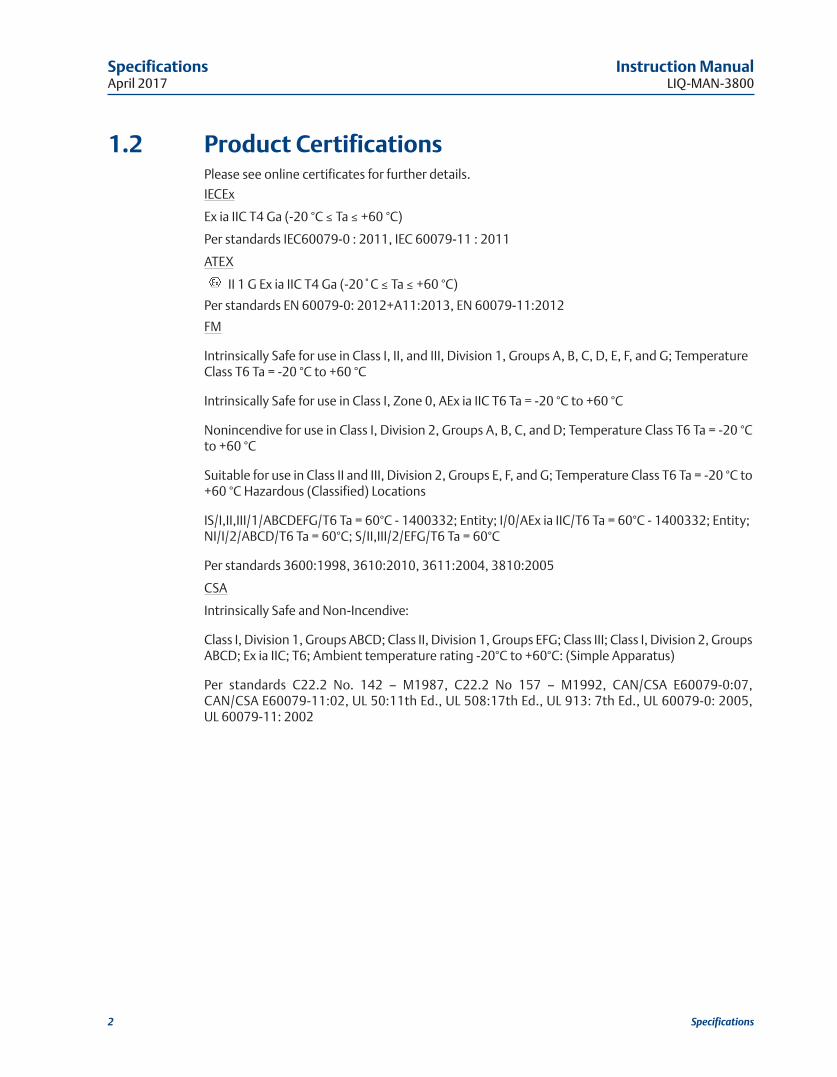
1.2 Product CertificationsPlease see online certificates for further details.
IECEx
Ex ia IIC T4 Ga (-20 °C ≤ Ta ≤ +60 °C)
Per standards IEC60079-0 : 2011, IEC 60079-11 : 2011
ATEX
II 1 G Ex ia IIC T4 Ga (-20˚C ≤ Ta ≤ +60 °C)
Per standards EN 60079-0: 2012+A11:2013, EN 60079-11:2012
FM
Intrinsically Safe for use in Class I, II, and III, Division 1, Groups A, B, C, D, E, F, and G; Temperature Class T6 Ta = -20 °C to +60 °C
Intrinsically Safe for use in Class I, Zone 0, AEx ia IIC T6 Ta = -20 °C to +60 °C
Nonincendive for use in Class I, Division 2, Groups A, B, C, and D; Temperature Class T6 Ta = -20 °Cto +60 °C
Suitable for use in Class II and III, Division 2, Groups E, F, and G; Temperature Class T6 Ta = -20 °C to+60 °C Hazardous (Classified) Locations
IS/I,II,III/1/ABCDEFG/T6 Ta = 60°C - 1400332; Entity; I/0/AEx ia IIC/T6 Ta = 60°C - 1400332; Entity; NI/I/2/ABCD/T6 Ta = 60°C; S/II,III/2/EFG/T6 Ta = 60°C
Per standards 3600:1998, 3610:2010, 3611:2004, 3810:2005
CSA
Intrinsically Safe and Non-Incendive:
Class I, Division 1, Groups ABCD; Class II, Division 1, Groups EFG; Class III; Class I, Division 2, GroupsABCD; Ex ia IIC; T6; Ambient temperature rating -20°C to +60°C: (Simple Apparatus)
Per standards C22.2 No. 142 – M1987, C22.2 No 157 – M1992, CAN/CSA E60079-0:07, CAN/CSA E60079-11:02, UL 50:11th Ed., UL 508:17th Ed., UL 913: 7th Ed., UL 60079-0: 2005, UL 60079-11: 2002

Installation 3
Section 2: Installation
Instruction Manual InstallationLIQ-MAN-3800 April 2017
2.1 Unpacking and InspectionInspect the outside of the carton for any damage. If damage is detected, contact the carrier immediately. Inspect the instrument and hardware. Make sure all items in the packing list are present and in good condition. Notify the factory if any part is missing.
2.2 Storage1. It is recommended that electrodes be stored in their original shipping containers until
needed.
2. Do not store at temperatures below 23 °F (-5 °C).
3. Electrodes should be stored with a protective cap containing KCl solution (PN 9210342).
4. For overnight storage, immerse the sensor in tap water or 4 pH buffer solution.
5. A pH glass electrode does have a limited shelf life of one year.
2.3 Electrode Preparation1. Remove electrode from shipping container.
2. Remove the protective boot covering the electrode bulb.
3. Rinse away salt film with clean water, then shake the electrode so that the internal solution fills the bulb, thus removing any air trapped there.
Note: Do not allow lubricant to coat electrode bulb or reference junction. If it does, wipe it cleanbefore installation.

4 Installation
Installation Instruction ManualApril 2017 LIQ-MAN-3800
Figure 2-1: Rosemount 3800 dimensional drawing
Figure 2-2: Sensor orientation

Wiring 5
Instruction Manual WiringLIQ-MAN-3800 April 2017
3.1 Wiring for Rosemount 3800For other wiring diagrams not shown below, please refer to the Liquid Transmitter Wiring Diagrams.
Section 3: Wiring
Figure 3-1: Rosemount 3800 sensor wiring to Rosemount 1056/56/1057 transmitters

6 Wiring
Wiring Instruction ManualApril 2017 LIQ-MAN-3800
Figure 3-2: Rosemount 3800 sensor wiring to Rosemount 1066 transmitter
Figure 3-3: Rosemount 3800 sensor wiring to Rosemount 5081 transmitter

4.1 Two Point Buffer CalibrationSelect two stable buffer solutions, preferably pH 4.0 and 7.0 (pH buffers other than pH 4.0 and pH 7.0 can be used as long as the pH values are at least two pH units apart).
Note: A pH 7 buffer solution reads a mV value of approx. zero, and pH buffers read approximately±59.1 mV for each pH unit above or below pH 7. Check the pH buffer manufacturer specifications for millivolt values at various temperatures since it may affect the actual value of the buffer solution mV/pH value.
1. Immerse sensor in the first buffer solution. Allow sensor to equilibrate to the buffer temperature (to avoid errors due to temperature differences between the buffer solutionand sensor temperature) and wait for reading to stabilize. Value of buffer can now be acknowledged by transmitter.
2. Once the first buffer has been acknowledged by the transmitter, rinse the buffer solution off of the sensor with distilled or deionized water.
3. Repeat steps 1 and 2 using the second buffer solution.
4. The theoretical slope value, according to the Nernst equation for calculating pH, is approximately 59.17 mV/pH. Over time the sensor will age, both in the process and in storage, and will result in reduced slope values. To ensure accurate readings, it is recommended that the electrode be replaced when the slope value falls below 47 to 49 mV/pH.
4.2 Recommended pH Sensor StandardizationFor maximum accuracy, the sensor can be standardized on-line or with a process grab sample aftera buffer calibration has been performed and the sensor has been conditioned to the process. Standardization accounts for the sensor junction potential and other interferences. Standardization will not change the sensor’s slope but will simply adjust the analyzer’s reading tomatch that of the known process pH.
Section 4: Calibration
Calibration 7
Instruction Manual CalibrationLIQ-MAN-3800 April 2017

8 Calibration
Calibration Instruction ManualApril 2017 LIQ-MAN-3800

Maintenance 9
Section 5: Maintenance
Instruction Manual MaintenanceLIQ-MAN-3800 April 2017
5.1 MaintenanceElectrodes should respond rapidly. Sluggishness, offsets, and erratic readings are indicators that the electrodes may need cleaning or replacement.
1. To remove oil deposit, clean the electrode with a mild non-abrasive detergent.
2. To remove scale deposits, soak electrodes for 30 to 60 minutes in a 5% hydrochloric acid solution.
3. Temperature effect on life expectancy: If glass electrode life expectancy is 100% @ 25 °C (77 °F), then it will be approximately 25% @ 80 °C (176 °F), and approximately 5% @ 120 °C(248 °F).

10 Maintenance
Maintenance Instruction ManualApril 2017 LIQ-MAN-3800
Accessories 11
Instruction Manual AccessoriesLIQ-MAN-3800 April 2017
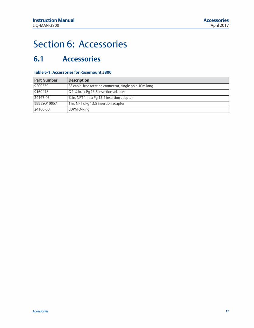
6.1 Accessories
Table 6-1: Accessories for Rosemount 3800
Section 6: Accessories
Part Number Description9200339 S8 cable, free rotating connector, single pole 10m long
9160478 G 1 ¼ in. x Pg 13.5 insertion adapter
24167-03 ¾ in. NPT 1 in. x Pg 13.5 insertion adapter
9999SQ10057 1 in. NPT x Pg 13.5 insertion adapter
24166-00 EDPM O-Ring

Maintenance Instruction ManualApril 2017 LIQ-MAN-3800
12 Accessories

EC Declaration of Conformity 13
EC Declaration of ConformityNote: Please see website for most recent Declaration.
Instruction Manual EC Declaration of ConformityLIQ-MAN-3800 April 2017

14 EC Declaration of Conformity
EC Declaration of Conformity Instruction ManualApril 2017 LIQ-MAN-3800

FM Installation 15
Intrisicallly Safe Sensor Installation Drawing - FM
ANY
FM A
PPRO
VED
ASSO
CIAT
ED A
PPAR
ATU
SH
AVIN
G E
NTI
TY P
ARAM
ETER
S
NO
N- H
AZA
RD
OU
S (U
NC
LASS
IFIE
D)
AR
EA
CLAS
S I,
II, II
I, D
IVIS
ION
1, G
ROU
PS A
-GT6
Ta
= 60
°C
SEN
SOR
ENTI
TY P
ARAM
ETER
SU
i =
13.1
U, I
i =
358
mA
Pi =
698
mW
Ci
= 0.
967
µF, L
i = 0
.1m
H
1. N
O R
EVIS
ION
TO
TH
IS D
RAW
ING
IS P
ERM
ITTE
D W
ITH
OU
TFM
APP
ROV
AL.
2. U
max
> U
t ; Im
ax >
I t; (
CiO
F AL
L LO
OPS
+ C
CAB
LE) <
Ca
;
(L i
OF
ALL
LOO
PS +
L C
ABLE
) < L
a, P
max
OR
Pi >
P0.
3. S
ING
LE M
ULT
I-CH
ANN
ELIS
BAR
RIER
OR
APPA
RATU
S M
UST
BE
FM A
PPRO
VED
,
4. S
ING
LE M
ULT
I-CH
ANN
ELIS
BAR
RIER
OR
APPA
RATU
S M
ANU
FACT
URE
'S
CO
NTR
OL
DRA
WIN
GS
MU
ST B
E FO
LLO
WED
WH
EN IN
STAL
LIN
G T
HE
SYST
EM.
IS B
ARRI
ER O
R EQ
UIP
MEN
T M
AY B
E IN
STAL
LED
WIT
HIN
TH
E H
AZAR
DO
US
(C
LASS
IFIE
D) L
OCA
TIO
N F
OR
WH
ICH
IT IS
APP
ROV
ED.
5. I
NST
ALLA
TIO
N M
UST
BE
IN A
CCO
RDAN
CE W
ITH
ART
ICLE
500
OF
THE
NEC
(
ANSI
/NFP
A 70
) AN
D A
NSI
/ISA
RP
12.6
.
WAR
NIN
G:
SUBS
TITU
TIO
N O
F CO
MPO
NEN
TS M
AY IM
PAIR
INTR
INSI
C SA
FETY
.
6. p
H &
AM
PERO
MET
RIC
SEN
SORS
WIT
HO
UT
PREA
MPS
ARE
SIM
PLE
APPA
RATU
S.
ZON
EZO
NE
0
7. C
ON
TRO
L EQ
UIP
MEN
T CO
NN
ECTE
D T
O T
HE
ASSO
CIAT
ED A
PPAR
ATU
S M
UST
N
OT
USE
OR
GEN
ERAT
E M
ORE
TH
AN 2
50V
.
RESI
STAN
CE B
ETW
EEN
INTR
INSI
CALL
Y SA
FE G
ROU
ND
AN
D E
ARTH
GRO
UN
D
MU
ST B
E LE
SS T
HAN
OR
EQU
AL T
O 1
OH
M.
ANY
FM A
PPRO
VED
TRA
NSM
ITTE
R FO
RD
IVIS
ION
1 W
ITH
INTR
INSI
CALL
Y SA
FEO
UTP
UT
PARA
MET
ERS.
TH
ISFM
APPR
OV
ED D
EVIC
E M
UST
BE
INST
ALLE
DPE
R IT
S IN
STAL
LATI
ON
DRA
WIN
G.
FMAP
PRO
VED
EQ
UIP
MEN
T (M
AY B
EM
ULT
IPLE
DEV
ICES
, NU
MBE
R IS
LIM
ITED
BY R
EQU
IREM
ENTS
TO
MEE
T AL
L O
THER
IS R
EQU
IREM
ENTS
FO
R TH
E N
ETW
ORK
)W
ITH
EQ
UIV
ALEN
T H
AZAR
DO
US
AREA
APPR
OV
ALS.H
AZA
RD
OU
S (C
LASS
IFIE
D) A
REA
INTR
ISIC
ALL
Y S
AFE
9. p
H/O
RP S
ENSO
R M
OD
ELS
THAT
MAY
CO
NTA
IN T
HE
PREA
MPL
IFIE
R:
3900
/VP
3500
/VP
3300
HT/
VP
3400
HT/
VP
396/
VP
396R
/VP
396P
/VP
398R
/VP
399/
VP
389/
VP
385/
385+
10.
WAR
NIN
G:
TO P
REV
ENT
IGN
ITIO
N O
F FL
AMM
ABLE
OR
CO
MBU
STIB
LE
AT
MO
SPH
ERES
, DIS
CON
NEC
T PO
WER
BEF
ORE
SER
VIC
ING
.
11.
TH
E EN
TITY
CO
NCE
PT A
LLO
WS
INTE
CON
NEC
TIO
N O
F IN
TRIN
SICA
LLY
SAFE
APPA
RATU
S W
ITH
ASS
OCI
ATED
APP
ARAT
US
WH
EN T
HE
FOLL
OW
ING
IS T
RUE:
Ui>
Uo;
Ii>
Io;
Pi>
Po;
Co
> C
i + C
CAB
LE; L
o>
Li +
L C
ABLE
.
12.
CO
PY R
EVIS
ION
S TO
140
0332
TO
pH
/ORP
SH
IPPI
NG
MAN
UAL
S.
13
Ci I
NCL
UD
ES T
HE
CAPA
CITA
NC
E O
F 50
0 FE
ET O
F SE
NSO
R C
ABLE
.
13
DW
G N
O.
1400
332
8.
Instruction Manual FM InstallationLIQ-MAN-3800 April 2017

LIQ-MAN-3800Rev. D
April 2017
Emerson
8200 Market Blvd.Chanhassen, MN 55317,USA Tel +1 800 999 9307Fax +1 952 949 7001
Youtube.com/user/Rosemount
Twitter.com/Rosemount_News
Analyticexpert.com
facebook.com/Rosemount
©2017 Emerson. All rights reserved.
The Emerson logo is a trademark and service mark of Emerson Electric Co. Rosemount is a mark ofone of the Emerson family of companies. All other marks are the property of their respectiveowners.
The contents of this publication are presented for information purposes only, and while effort hasbeen made to ensure their accuracy, they are not to be construed as warranties or guarantees,express or implied, regarding the products or services described herein or their use or applicability.All sales are governed by our terms and conditions, which are available on request. We reserve theright to modify or improve the designs or specifications of our products at any time without notice.
www.Emerson.com/RosemountLiquidAnalysis


