
Motion Capture for RunnersDesign Team 8 - Spring 2013Members:Blake Frantz, Zhichao Lu, Alex Mazzoni, Nori Wilkins, Chenli Yuan, Dan Zilinskas
Sponsor:Air Force Research LaboratoryDr. Eric T. Vinande
Facilitator: Dr. Selin Aviyente

Outline● Introduction
○ Objective and Benefits● Proposed Solution● Design Specification
○ Project Components○ System Design○ Components
● Testing● Risk Analysis● Project Roles● Budget● Schedule
Introduction● The efficiency of a runner’s technique is directly
proportional to the quality of their posture.
● Different running conditions significantly changes the form of the runner (running uphill, jogging, sprinting).
● Similar studies focused on measurement and analysis of running form using three dimensional acceleration and gyroscopic sensors.
Objectives● Capture running motion by choosing proper sensors
● Develop recording system that receives data from sensors and sends data wirelessly to processor○ body-worn controller○ real-time processing on external PC
● Analyze motion data and provide real-time feedback to improve runner efficiency
● Analogous to understanding flexible structures on aircrafts and spacecrafts
System Benefits
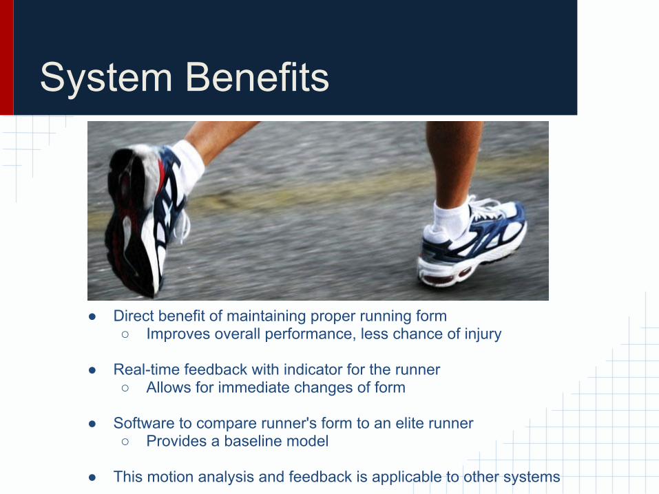
● Direct benefit of maintaining proper running form○ Improves overall performance, less chance of injury
● Real-time feedback with indicator for the runner○ Allows for immediate changes of form
● Software to compare runner's form to an elite runner○ Provides a baseline model
● This motion analysis and feedback is applicable to other systems
Proposed Solution● Body-worn Sensors
○ Inertial Measurement Units (IMUs)■ Accelerometer■ Gyroscope
○ Sensors wired to the body-worn Controller○ Sensors and controller sewn into bodysuit○ Used for treadmill purposes
● Body-worn Controller○ Preliminary data processing, time-stamping
● Wireless Communication○ Communication between body worn controller and PC○ Xbee, Wireless
● Real-time Processing○ Process data on PC○ Comparison software to compare with elite runner data
● Real-time Feedback○ Body-worn indicator: LED indication of proper or improper form

Design Specifications
● Battery○ Size○ Life
● Sensors○ Number of axes○ Power consumption○ Sampling Rate○ Size
● Wireless○ Bandwidth○ Range
● Cost

Project Components
IMU (Inertial Measurement Unit)- Device that measures velocity, orientation and gravity- Consists of an accelerometer, gyroscope and a compass- 9-axis measurements
Arduino Microcontroller- Acquires data from the IMU sensors- Synchronizes connected sensors- Arduino UNO, and Arduino Due

Project Components
ZigBee (XBee) Communication- Connects Arduino and PC wirelessly- Connects the PC to body-worn feedback controller
Arduino Micro SD Shield- Requires micro SD card- Connects to Arduino microcontroller- Provides additional memory for sensor data
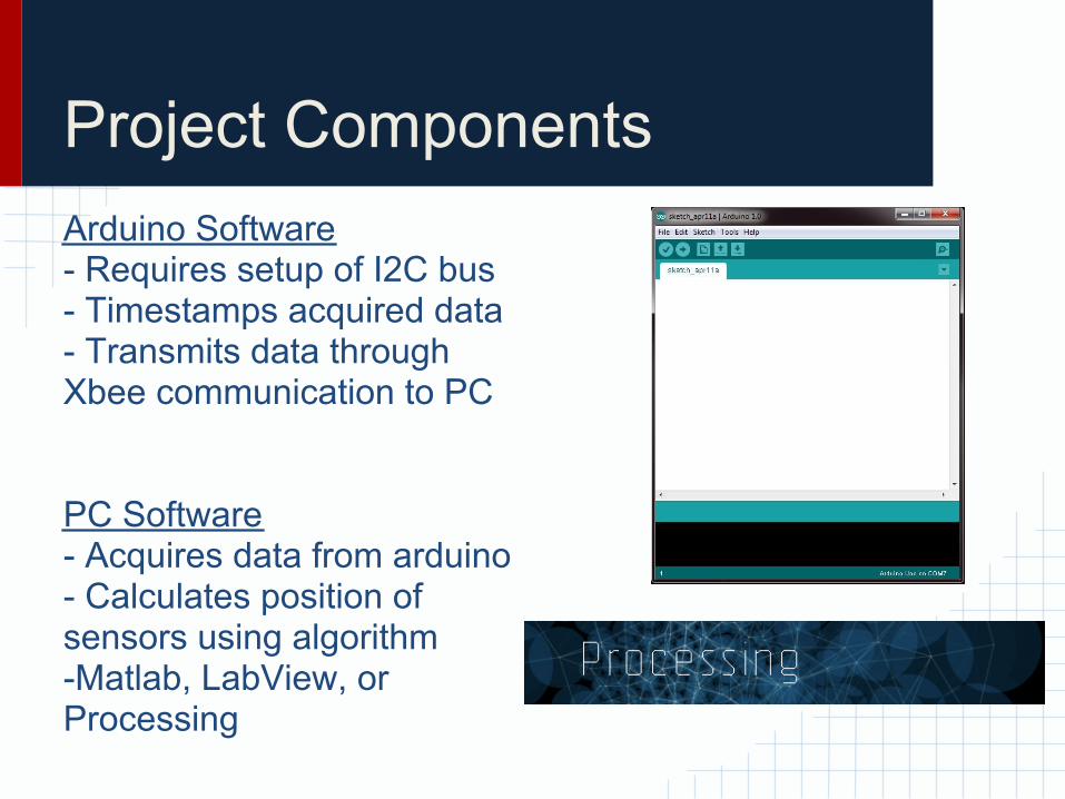
Project ComponentsArduino Software- Requires setup of I2C bus- Timestamps acquired data- Transmits data through Xbee communication to PC
PC Software- Acquires data from arduino- Calculates position of sensors using algorithm-Matlab, LabView, or Processing
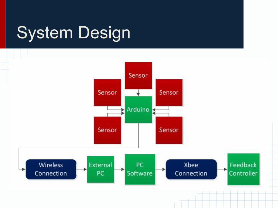
System Design

Testing● Sensors
○ Each sensor capturing data○ Sending directly to the Arduino board
● Arduino○ Time-stamping data properly○ Consistent data acquisition
● Communication○ Fast, noiseless wireless communication (Arduino to PC)○ Wire communication between IMUs and Arduino○ Easily understood and accurate feedback
● Software Testing○ Arduino○ PC acquisition data○ Comparison software consistent
Risk Analysis● Sensors
○ Power consumption○ Sampling rate of sensors
● Arduino○ Timestamping of acquired data
● Communication○ Bandwidth of communication devices○ Continuity of data acquisition (memory limitation)○ Transmission of data○ Synchronization○ Range
● Feedback○ Ease of interpreting form assessment

Project Roles
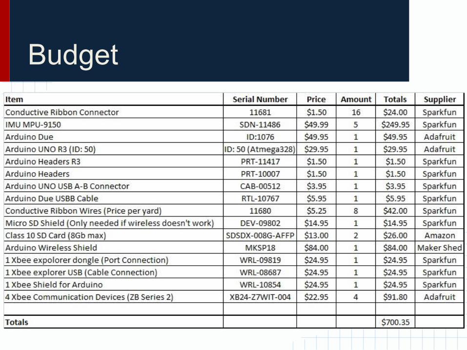
Budget
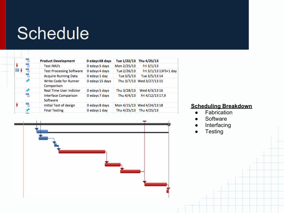
Schedule
Scheduling Breakdown● Fabrication● Software● Interfacing● Testing
Summary● Motion Capture
○ IMUs placed on body detect motion○ Arduino receives data and transmits to PC
● Analysis○ PC has elite runner reference motion○ Comparison Software
● Feedback○ Immediate real-time feedback to the runner for improper or proper
running form

Thank You and Questions
?


