
RV SATELLITE ANTENNA
AUTOMATIC SKEW TWIN LNB
SSA-850
INSTALLATION AND OPERATION MANUAL Please ensure that this manual is read in full prior
to installing or using this sphere satellite unit.
Design and specifications are subject to change without notice.
Made in Korea.
Notes, Cautions, and Warnings
Caution – Improper handling by unqualified personnel can cause serious
Damage to this equipment. Unqualified personnel who tamper with this
Equipment may be held liable for any resultant damage to the equipment.
Install under DRY CONDITIONS ONLY! Do not install this system in the
rain, Or under any wet conditions. Moisture may affect electronics and void
warranty!
Warning – Need 2 people to install the antenna onto the roof. Do not try to
install the antenna by yourself.
Note – Before you begin, carefully read each of the procedures in this
manual. If you have not performed similar operations on comparable
equipment, do not attempt to perform these procedures.
The Sphere SSA-850 RV Satellite Antenna with Auto skew TWIN LNB is innovative
and a technologically advanced satellite Positioner system. The antenna has a unique
combination of state-of-the art components with the most sophisticated satellite
acquisition and tracking programs to locate and lock onto the OPTUS C1/D3 Satellite in
Australia, provide the following features:
■ Auto Skew
■ Twin LNB
■ Fast satellite acquisition of the Optus C1/D3 satellite
■ Compatible* with any Satellite Receiver *(That Use a 10.700GHz L.O.)
■ Capable of High Definition receiving

Specification
Antenna Type Off-set Dish
Frequency Band Ku Band
LNB local oscillator (LO) 10.700 GHz
Antenna Dish Dimension 860x920mm
Polarization Horizontal and Vertical
Elevation Range 20° to 74°
Azimuth Range 365°
Tracking Rate 50°/sec
Temperate Range -20° to 70°
Power 12 VDC
Current Usage Max2.5A(Typ.1.6A) on SEARCH.
NO Current in Sleep mode
Antenna Weight 16kg - Roof unit ONLY.
19kg - Total Installed weight
Main System Components
Antenna Unit
The antenna unit houses the antenna positioning
Mechanism, LNB (low noise block), and control
Elements within the antenna. Weather tight
connectors join the power, signal, and control
cabling from the antenna IDU unit.
IDU (In Door Unit)
The IDU is the system’s user interface, providing
access to the system and its functions through an
LCD display Power and two control buttons.
IDU provides the power to the antenna as well as
receives the satellite signal from the antenna
unit.

This section offers a general explanation of how to correctly install the Sphere SSA-850
RV Satellite Antenna. Installation of the antenna is recommended to be fitted by a
Sphere Dealer, or RV Accessories fitter.
Unpacking the unit (2 boxes)
1. Open the Main box and remove packing material.
The following items are included in the packaging of the Main Antenna carton.
Item No. Description Quantity
1 Main Antenna Unit 1 each
2 IDU (In Door Unit) 1 each
3 Control Cable (7m) 1 each
4 Coaxial Cable (7m) 2 each
5 Coaxial Cable (1m) 1 each
6 Power Cable (1.5m) 1 each
7 Roof top cable junction box 1 each
8 Roof top cable entry plate 1 each
2. Open the Dish box and remove packing material.
1 85cm Antenna Dish Only 1 each
Ensure all above components are included before proceeding with the installation.
Should any parts be missing, please contact the selling dealer with the units serial
number handy.
Preparing for the installation
Install Tools and Materials
The antenna system is designed for simple installation and setup. However, the
following list of equipment or items should be available during installation of the
antenna.
■ Electric drill and drill bits
■ Socket wrench
■ Silicon sealant
■ Fastener suitable for specific application
1. Verification of the RV’s Power Supply.
■ Confirm that the RV’s power supply is 12VDC.
NOTE: Should IGN+ Close feature is to be installed/wired; permanent power
from the house battery is required. If this house power is to be isolated prior to
dish being fully closed, please contact [email protected] for further
assistance.
2. Verification of the Satellite Receiver and IDU’s attachment and the electricity
supply
■ Install the IDU and Satellite Receiver in the interior of the RV.
■ Connect power to IDU and Satellite Receiver.
■ Once the power of IDU and Satellite Receiver is verified, confirm that
both IDU and Satellite Receiver are working normally.
3. Procedure of the satellite’s attachment and installation.
■ Installation of the satellite must be on the flat roof surface area of the RV.
■ Connect 2x 7m coaxial cables and 1x 7m control cable to the satellites
Terminals.
■ Connect the IDU and the Satellite Receiver box with each of the coaxial cables.
■ Make sure that the satellite is working normally, once the power is supplied.
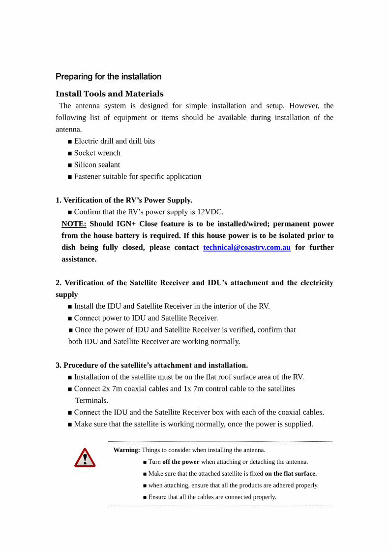
Warning: Things to consider when installing the antenna.
■ Turn off the power when attaching or detaching the antenna.
■ Make sure that the attached satellite is fixed on the flat surface.
■ when attaching, ensure that all the products are adhered properly.
■ Ensure that all the cables are connected properly.
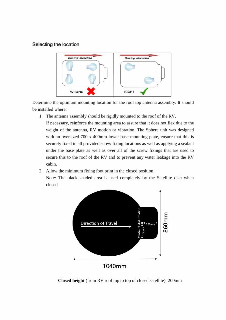
Selecting the location
Determine the optimum mounting location for the roof top antenna assembly. It should
be installed where:
1. The antenna assembly should be rigidly mounted to the roof of the RV.
If necessary, reinforce the mounting area to assure that it does not flex due to the
weight of the antenna, RV motion or vibration. The Sphere unit was designed
with an oversized 700 x 400mm lower base mounting plate, ensure that this is
securely fixed in all provided screw fixing locations as well as applying a sealant
under the base plate as well as over all of the screw fixings that are used to
secure this to the roof of the RV and to prevent any water leakage into the RV
cabin.
2. Allow the minimum fixing foot print in the closed position.
Note: The black shaded area is used completely by the Satellite dish when
closed
Closed height (from RV roof top to top of closed satellite): 200mm
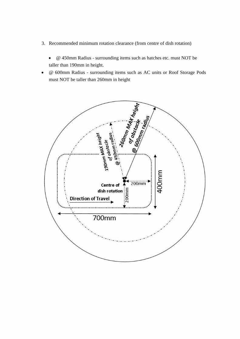
3. Recommended minimum rotation clearance (from centre of dish rotation)
@ 450mm Radius - surrounding items such as hatches etc. must NOT be
taller than 190mm in height.
@ 600mm Radius - surrounding items such as AC units or Roof Storage Pods
must NOT be taller than 260mm in height

Installing the roof top dish antenna
Once the location of the antenna has been selected, prepare the area of the RV
roof to glue and screw the roof top unit assembly into position. Screw location
fixing points have been provided, should you need additional fixing locations
mark and drill these as required.
Ensure that all screw fixings are covered with sealant to ensure that there are no
leaks into the RV.
Installing the roof top cable cover and entry plate
Once the antenna has been installed, the cover and cable entry plate needs to be
installed.
Example of cable cover and entry plate ready to be glued and screwed into position.

The Cable cover is to be placed between the antenna and the cable entry plate.
This houses the 2x coax feeds and the main control cable connection plug.
The base of this cover is to be glued and screwed to the roof of the RV, the
cover is then placed over this and screwed in place. NOTE: DO NOT Glue the
top white cover in place, this is held to the base plate with the 4x provided
screws.
Drill an entry hole in the required position of 35-40mm to allow the main
control connection to pass through the hole from inside the RV (A smaller hole
can be used if you are to feed the complete loom from the roof down) This hole
is used to pass the 2x coax cables and main control cable through the roof of the
RV. Pass the cables through the hole and ensure that the cable entry plate is
covering the hole and mark the locations for the screw fixing holes to pre-drill
the roof. Apply sealant around the cable entry plate base and ensure that enough
sealant is used at the opening of the plate where the cables exit. Screw the cover
plate down and apply sealant over each screw to ensure no leaks are seen into
the RV.
Example of cable entry plate ready to be glued and screwed into position.

Installing the dish to the roof top antenna assembly
Once power and control cables are connected, follow the operation steps below
to enable the dish bracket to rise, once the Dish bracket is raised and before the
unit has started to rotate the IDU needs to be paused to allow the dish skin to be
added.
Remove the screws from the dish bracket and align the dish to the dish bracket.
Fix the dish skin in place with the screws provided and follow the steps to close
the dish.
Power up to open the dish bracket
Press the POWER button
Press the SEARCH button
Once the dish bracket is in the open/upright position press and HOLD the
SEARCH and CLOSE buttons for 3Seconds, the IDU will power off and
stay open. Attach the dish skin to the dish bracket.
Power up to return to the closed position with dish skin fitted.
Press the POWER button
Press the CLOSE button, the IDU will power off when the dish is closed.

Equipment and cable installation
This offers a general explanation of how to install the IDU and ‘Satellite receiver’
(Satellite receiver is Not supplied in this kit), to the inside of the RV, connecting with
the Main Control Cable and 2x coaxial cables.
1. The 2x Coaxial cables and Main Control cable is routed from the antenna to the
IDU inside the RV.
2. After once deciding where to place the IDU and satellite receiver, make sure that
both units are placed in a dry and protected area.
3. The IDU and satellite receiver should be placed away from any heat source and in
an area with proper ventilation.
4. Ensure that there are at least 3cm of space around both units for ventilation and
connection of cables. Do not stack the units on top of each other.
5. The following describes the basic wiring configurations for the antenna system.
Connect the Main Control Cable to the Main cable connection on the rear of
the IDU.
Connect 1x Coaxial cable to the ‘Antenna’ port on the back of the IDU.
Connect the 2nd
Coaxial cable to the Satellite receiver installed into the RV.
Optional(2nd
Satellite Receiver/or Twin Tuner Satellite receiver connection)
Connect the 1m Coaxial cable to the ‘Receiver’ port on the IDU and connect
this to the 2nd
Satellite Receiver (or to the 2nd
LNB input of a Twin Tuner
Satellite receiver.)
6. Connecting power to the IDU
RED Wire = Connect to Max.5A FUSED 12V (+) Pos. Power circuit of the
RV house battery.
THICK BLACK Wire = Connect to RV Battery Negative (-) / Common
Ground circuit.
YELLOW*(Optional, May involve extra fitting costs) = Connect to Max.5A
FUSED 12V IGN(+) Pos. Power circuit of the RV Chassis/Start battery
(Ignition feed from Key Switch) *NOTE* RED Wire of IDU needs to have
Permanent power supply for this IGN+ Close option to function
Thin Black = Connect to RV Chassis/Start Battery Negative (-) or Common
Ground circuit.

REAR OF IDU
12VDC
Control Connector
RECEIVER
ANTENNA
RV 12V BATT
5A Fuse*
5A Fuse*
Connection diagram
AV lead AV lead
NOTE: If set-top box No.1 is a
TWIN Tuner receiver, then also
connect coax cable from IDU
‘Receiver’ port to the 2nd
input.
Control cable
Coax Cable
Set-top box 1 Set-top box 2
(Optional)
*Optional IGN(+)
AUTO CLOSE
Fuse* NOT
supplied
*Neg (-) for IGN Close

The Sphere SSA-850 RV Satellite Antenna system was designed for its ease of use. This
has been programmed to locate the OPTUS C1/D3 series satellite for receiving of TV
broadcast signals. Two Operation zones were added to aid in the search time,
OPTUS C1/D3 EAST and OPTUS C1/D3 WEST. The Antenna unit initialization and
satellite acquisition is completely hassle free.
Receiving Satellite TV Signals
Television satellites are located in fixed positions above the Earth’s equator and beam
TV signals down to certain regions of the planet. To receive TV signals from a satellite,
you must be located within that satellite’s unique coverage area. In addition, since TV
satellites are located above the equator, the antenna must have a clear view of the sky to
receive satellite TV signals. Anything that stands between the antenna and the satellite
can block the signal, resulting in lost reception. Common causes of blockage include
trees, buildings, and mountains. Heavy rain, ice, or snow might also temporarily
interrupt satellite signals.

Turning the System On/Off
Since power to the antenna system is controlled by the IDU, you can turn the antenna
on or off by applying power to the IDU.
Turning on the System
Follow the steps below to turn on your antenna System.
1. Make sure the antenna has a clear view of the sky.
2. Turn on your satellite TV receiver and TV.
3. Press the POWER button on the IDU.
4. When the display powers up. Press the SEARCH button. The IDU will
display the OPTUS C1/D3 EAST, if you are in the EAST Zone, and
then allow the unit to start tracking. If you are in the WEST Zone
(please refer to the zone map) while the display is flashing quickly
(approx. 3 second window), press again the SEARCH button to toggle
to OPTUS C1/D3 WEST. The IDU will now control the Antenna, please
allow the satellite to rotate and search for the selected satellite. Once the
IDU locates the satellite and adjusts the Elevation/Direction and final
LNB Skew setting for your area, the IDU Display will power OFF to
save power.
Turning off the System (To CLOSE the DISH)
Follow the steps below to CLOSE the dish and to turn off your antenna System.
1. Press the POWER button on the IDU.
(This will ‘wake up’ the IDU from its sleep mode.)
2. Press the CLOSE button on the IDU, this will start to close the dish to
the home/closed position ready for travel. Once this is completely
closed the IDU display with power off and go back into Sleep mode.
3. Turn off your Satellite TV receiver and TV.

OPTUS C1/D3 ZONE MAP
Once you have pulled up at your next camp for the night or many weeks, follow the
below map as a guide for the EAST/WEST Zones that have been setup in the IDU
Software. Be selecting the correct zone this will allow the Satellite unit to locate and
lock onto the OPTUS C1/D3 within a few minutes. The IDU Uses the feature of ‘LEM’
(Last Elevation Memory) so if you have only travelled a few hundred Kilometers since
your last stop the satellite tracking will be quite fast at approx. 1-2minutes for the
Sphere Satellite unit to locate and lock onto the satellite once again. If you have traveled
some greater distance e.g. from Perth to Cairns without using the satellite on your
travels, this may take up to approx. 10minutes to locate and lock onto the OPTUS
C1/D3 Satellite. (This also may be seen on your very first setup of the satellite antenna.)
OPTUS C1/D3
WEST ZONE
OPTUS C1/D3
EAST ZONE
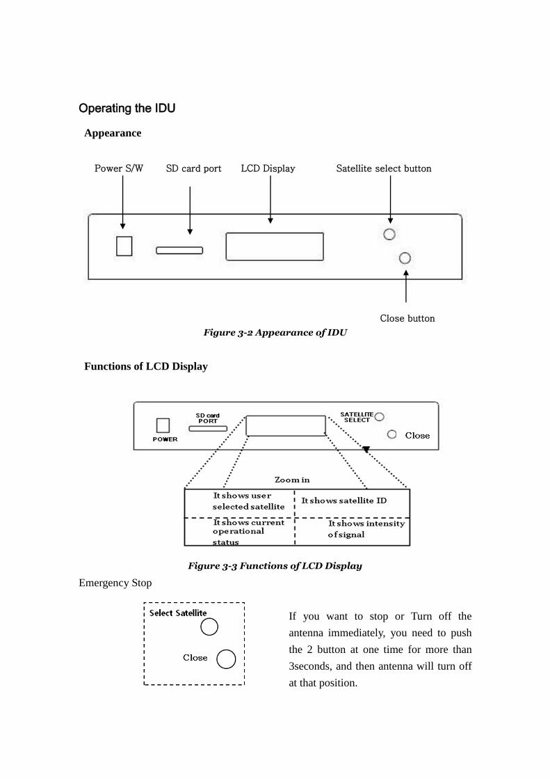
Operating the IDU
Appearance
Figure 3-2 Appearance of IDU
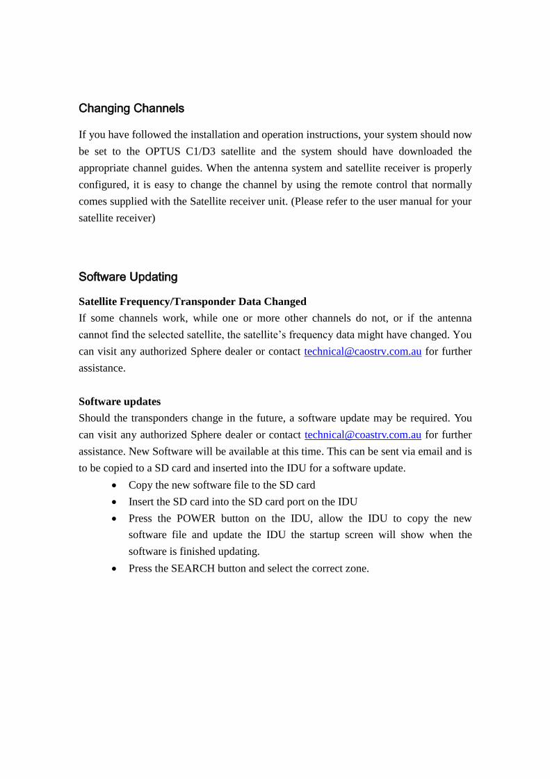
Functions of LCD Display
Figure 3-3 Functions of LCD Display
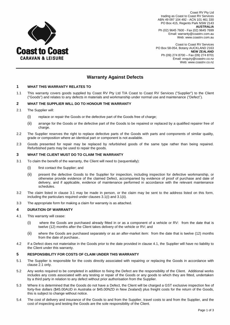
Emergency Stop
If you want to stop or Turn off the
antenna immediately, you need to push
the 2 button at one time for more than
3seconds, and then antenna will turn off
at that position.
Power S/W LCD Display Satellite select button
Close button
SD card port
Changing Channels
If you have followed the installation and operation instructions, your system should now
be set to the OPTUS C1/D3 satellite and the system should have downloaded the
appropriate channel guides. When the antenna system and satellite receiver is properly
configured, it is easy to change the channel by using the remote control that normally
comes supplied with the Satellite receiver unit. (Please refer to the user manual for your
satellite receiver)
Software Updating
Satellite Frequency/Transponder Data Changed
If some channels work, while one or more other channels do not, or if the antenna
cannot find the selected satellite, the satellite’s frequency data might have changed. You
can visit any authorized Sphere dealer or contact [email protected] for further
assistance.
Software updates
Should the transponders change in the future, a software update may be required. You
can visit any authorized Sphere dealer or contact [email protected] for further
assistance. New Software will be available at this time. This can be sent via email and is
to be copied to a SD card and inserted into the IDU for a software update.
Copy the new software file to the SD card
Insert the SD card into the SD card port on the IDU
Press the POWER button on the IDU, allow the IDU to copy the new
software file and update the IDU the startup screen will show when the
software is finished updating.
Press the SEARCH button and select the correct zone.

Page 1 of 3
Coast RV Pty Ltd trading as Coast to Coast RV Services
ABN 49 097 104 492 - ACN 101 461 330 PO Box 415, Regents Park NSW 2143
AUSTRALIA Ph (02) 9645 7600 - Fax (02) 9645 7699
Email: [email protected] Web: www.coastrv.com.au
Coast to Coast RV Services
PO Box 58-054, Botany AUCKLAND 2163 NEW ZEALAND
Ph (09) 274 8700 – Fax (09) 274 8701 Email: [email protected]
Web: www.coastrv.co.nz
Warranty Against Defects
1 WHAT THIS WARRANTY RELATES TO
1.1 This warranty covers goods supplied by Coast RV Pty Ltd T/A Coast to Coast RV Services ("Supplier") to the Client ("Goods") and relates to any defects in materials and workmanship under normal use and maintenance (“Defect”).
2 WHAT THE SUPPLIER WILL DO TO HONOUR THE WARRANTY
2.1 The Supplier will:
(i) replace or repair the Goods or the defective part of the Goods free of charge;
(ii) arrange for the Goods or the defective part of the Goods to be repaired or replaced by a qualified repairer free of charge.
2.2 The Supplier reserves the right to replace defective parts of the Goods with parts and components of similar quality, grade or composition where an identical part or component is not available.
2.3 Goods presented for repair may be replaced by refurbished goods of the same type rather than being repaired. Refurbished parts may be used to repair the goods.
3 WHAT THE CLIENT MUST DO TO CLAIM THE WARRANTY
3.1 To claim the benefit of the warranty, the Client will need to (sequentially):
(i) first contact the Supplier; and
(ii) present the defective Goods to the Supplier for inspection, including inspection for defective workmanship, or otherwise provide evidence of the claimed Defect, accompanied by evidence of proof of purchase and date of delivery, and if applicable, evidence of maintenance performed in accordance with the relevant maintenance schedules.
3.2 The claim listed in clause 3.1 may be made in person, or the claim may be sent to the address listed on this form, including the particulars required under clauses 3.1(i) and 3.1(ii).
3.3 The appropriate form for making a claim for warranty is as attached.
4 DURATION OF WARRANTY
4.1 This warranty will cease:
(i) where the Goods are purchased already fitted in or as a component of a vehicle or RV: from the date that is twelve (12) months after the Client takes delivery of the vehicle or RV; and
(ii) where the Goods are purchased separately or as an after-market item: from the date that is twelve (12) months from the date of purchase..
4.2 If a Defect does not materialise in the Goods prior to the date provided in clause 4.1, the Supplier will have no liability to the Client under this warranty.
5 RESPONSIBILITY FOR COSTS OF CLAIM UNDER THIS WARRANTY
5.1 The Supplier is responsible for the costs directly associated with repairing or replacing the Goods in accordance with clause 2.1 only.
5.2 Any works required to be completed in addition to fixing the Defect are the responsibility of the Client. Additional works includes any costs associated with any testing or repair of the Goods or any goods to which they are fitted, undertaken by a third party in relation to any defect without prior authorisation from the Supplier.
5.3 Where it is determined that the Goods do not have a Defect, the Client will be charged a GST exclusive inspection fee of forty-five dollars ($45.00AUD in Australia or $45.00NZD in New Zealand) plus freight costs for the return of the Goods, this is subject to change without notice.
5.4 The cost of delivery and insurance of the Goods to and from the Supplier, travel costs to and from the Supplier, and the cost of inspecting and testing the Goods are the sole responsibility of the Client.

Page 2 of 3
6 WARRANTY LIMITATIONS
6.1 The Supplier makes no warranties or representations other than those set out in this warranty document except as is required by law.
6.2 The Supplier will not be liable under this warranty:-
(i) to the Client or any other person for any consequential, direct or indirect loss, damage or costs incurred or suffered by the Client or any other person, including but not limited to damage to persons, other property, loss of turnover, loss of profits, loss of business or goodwill;
(ii) to the Client for transportation or travel costs which are the Client's responsibility;
(iii) for damage or defects in any Goods caused by improper transportation, storage or any other misuse, neglect or accident.
(iv) for the installation of the Goods. Any fault or defect due to installation should be referred to the installer. The Goods must be installed in accordance with the Manufacturer’s instructions and any relevant legislation or code.
6.3 This warranty covers the Client only and it is not transferrable if the Goods are sold by the Client during the warranty period.
7 WARRANTY EXCLUSIONS
7.1 This warranty will not apply where:
(i) the Goods have been improperly modified or repaired or the Good's defect has arisen due to the Client's failure to properly install, fit, maintain, service or use the Goods in accordance with the specifications and instructions provided by the Manufacturer, including a failure to comply with the relevant maintenance schedule (where applicable);
(ii) the Supplier cannot establish any Defect in the Goods after testing;
(iii) the Goods have been used other than for the purpose for which they were designed;
(iv) the Goods have been subject to abnormal conditions, including but not limited to temperature, pressure, stress, load or similar;
(v) the Client or installer have used or fitted non-genuine or non-approved parts and accessories to the Goods or have failed to use recommended parts and accessories;
(vi) the Good's defect has arisen due to abuse, misuse, neglect or accident;
(vii) the Goods have not been installed in accordance with the relevant instructions;
(viii) the Good’s defect is caused by use or fair wear and tear of the Goods (or expendable parts).
8 RIGHTS AT LAW
8.1 The benefits given to the Client under this warranty are in addition to other rights and remedies of the Client at law in relation to the Goods.
8.2 In Australia our Goods come with guarantees that cannot be excluded under the Australian Consumer Law. You are entitled to a replacement or refund for a major failure and for compensation for any other reasonably foreseeable loss or damage. You are also entitled to have the Goods repaired or replaced if the Goods fail to be of acceptable quality and the failure does not amount to a major failure.
Page 3 of 3
WARRANTY CLAIM FORM
Warranty Providers Name: Coast RV Pty Ltd trading as Coast to Coast RV Services
ABN 49 097 104 492 - ACN 101 461 330
Warranty Providers Address: PO Box 415 Regents Park NSW 2143 Australia OR;
PO Box 58-054 Botany AUCKLAND 2163 New Zealand
Client:
Contact No.
Description of Goods provided:
Receipt enclosed: (tick box) Yes No
Receipt No:
Description of defects (Give as much detail as possible. Use a separate page if required):
Date of purchase/services provided:
I hereby declare that the information provided above is true and correct and to the best of my knowledge and belief and I have complied with all the conditions of the warranty.
Signed:.....................................................................
Name: ...................................................................... (please print)
Dated: ......................................................................
[Please note, the issue or completion of this form by the Client does not constitute an admission of liability by the Supplier]


