
g GE Energy Services
S T E A M T U R B I N E I N S P E C T I O N R E P O R T
ADSP Installation
for
AMERICAN ELECTRIC POWER COMPANY INC
MITCHELL, Unit 2
Equipment Serial #: 170X394
Job Start Date: 9/12/2005
Report Issued: 02/08/06
FSR#: 96CE0024
Report Printed: January 30, 2006
Prepared By: Approved By:
Tom Perkins David Talmage
Field Engineer Service Manager
KPSC Case No. 2012-00578 Staff's First Set of Data Requests
Item No. 33 Attachment 13
Page 1 of 93

g GE Energy Services
TABLE OF CONTENTS
170X394 AMERICAN ELECTRIC POWER COMPANY INC Page 2
PAGE
JOB SUMMARY 3
INSPECTION SUMMARY 5
RECOMMENDATIONS 9
PARTS USED AND RECOMMENDED 12
TIL/ECN ACTIVITY 13
NOZZLES 14
TURBINE SHELLS 20
TURBINE ROTOR 41
DIAPHRAGM 45
SHAFT & DIAPHRAGM PACKING 51
TURBINE ALIGNMENT & CLEARANCES 58
BEARINGS 76
LUBRICATION SYSTEM 83
TURNING GEAR 85
STANDARDS 86
CONTROL SYSTEM 87
ALIGNMENT & CLEARANCE OVERVIEW 88
STARTUP COMMENTS 90
APPENDIX 93
KPSC Case No. 2012-00578 Staff's First Set of Data Requests
Item No. 33 Attachment 13
Page 2 of 93

g GE Energy Services
JOB SUMMARY
170X394 AMERICAN ELECTRIC POWER COMPANY INC Page 3
Customer: AMERICAN ELECTRIC POWER COMPANY IN
Station: MITCHELL
Unit No.: 2
Equipment Serial #: 170X394 Rating: 738 MW
Turbine Type: G5E Service Year: 1971
Eng. Responsibility: LST
Generator Code: Control System: Non-GE
LSB Length: 33.5 Generator Cooling: H
Service Type: Tech Direction
Steam Conditions:
Inlet Pressure: 3334 PSI Inlet Temperature: 1000 Deg F
Office Location: CENT FS-PITTSBURGH
FSR#: 96CE0024
Service Manager: David Talmage
Service Director: Dot Harris
Field Engineer: Tom Perkins
Job Start Date: 9/12/2005 Completion Date: 1/4/2006
Job Type: Major
Work Scope: [Y] Turbine [N] Generator [N] Valves [N] Auxiliary
[N] Other
KPSC Case No. 2012-00578 Staff's First Set of Data Requests
Item No. 33 Attachment 13
Page 3 of 93

g GE Energy Services
JOB SUMMARY
170X394 AMERICAN ELECTRIC POWER COMPANY INC Page 4
Unit #2 was removed from service September 9, 2005, for a scheduled maintenance outage. GE
responsibility for this outage was limited to the ADSP installation. GE provided (MPL-
1LX0365) parts, project management and technical direction. Labor and supervision were
provided by AEP. The turbine outage was scheduled for thirteen weeks, two ten hour shifts, six
days per week during disassembly and reassembly and five days per week while inner shell and
components were off site.
Additional turbine work performed this outage included internal inspection of the second reheat,
and valves. This work was performed under customer direction without GE involvement.
KPSC Case No. 2012-00578 Staff's First Set of Data Requests
Item No. 33 Attachment 13
Page 4 of 93

g GE Energy Services
INSPECTION SUMMARY
170X394 AMERICAN ELECTRIC POWER COMPANY INC Page 5
Section
Component
Location Description Action
Nozzle Box
Assembly HP Preventive Maintenance Replaced
Partition Erosion Spe Replaced
Ring Inlet Seal ASSOCIATED PARTS
HP Outer Shell
Fit Inner Shell - LH Cracked Weld Repaired
Fit Mid-span Seal Ring Damaged Weld Repaired
Flange Inlet Distortion Machined
Guide Thermocouple Preventive Maintenance New Part Installed
Inlet Bore Lower Left Fretted Machined
Inlet Bore Upper Left Fretted Weld Repaired
Insulation Improperly Installed Temporary Repair
Pipe Extraction Cracked Ground
Pipe Mid-span Access Damaged Replaced
Pressure Tap 1st and 3rd Sta Preventive Maintenance Replaced
Shell N1, N3 Improperly Installed Modified
Snout Reheat Inlet Pipe Out Of Round Machined
Stud 31 Broken Replaced
HP Inner Shell
Assembly FMI FMI Satisfied
Assembly Preventive Maintenance Repaired
Fit RS 3rd Sta PT Pounded Weld Repaired
Flange UH Cracked Weld Repaired
Gib Circular Key Corrosion Stoned
Key Joint Modification Modified
Orifice Cooling Pipe Plugged Repaired
Ring Reheat Extr Preventive Maintenance Replaced
KPSC Case No. 2012-00578 Staff's First Set of Data Requests
Item No. 33 Attachment 13
Page 5 of 93

g GE Energy Services
INSPECTION SUMMARY
170X394 AMERICAN ELECTRIC POWER COMPANY INC Page 6
Section
Component
Location Description Action
Ring Reheat Inlet Seal Preventive Maintenance Replaced
Snout MSI Pipe Preventive Maintenance New Part Installed
Shell
Bolt Bolt Stretch Bolting Stretched To Specification
Ring Inlet Seal Preventive Maintenance Modified
Ring Midspan Access Seal Preventive Maintenance Replaced
HP/RHT Rotor
Assembly FMI FMI Satisfied
Coupling A Preventive Maintenance Machined
LP B Rotor
Guard C Coupling Rubbed Ground
HP Diaphragm
Assembly HP/RH FMI FMI Satisfied
Partition 5, 6 Damaged Foreign Matl Modified
Spill Strip 2 Improperly Installed Modified
Shaft Packing
Assembly Diaphragm,Steam Seal Preventive Maintenance New Part Installed
HP Diaphragm Packing
Teeth 2nd Stage Damaged Modified
Packing Casing
Assembly N1, N3 Dimensional Checks Ok - Measurements Are Within Tolerance
Packing Head
KPSC Case No. 2012-00578 Staff's First Set of Data Requests
Item No. 33 Attachment 13
Page 6 of 93

g GE Energy Services
INSPECTION SUMMARY
170X394 AMERICAN ELECTRIC POWER COMPANY INC Page 7
Section
Component
Location Description Action
Assembly N1 Preventive Maintenance Realigned
Assembly N1, N3 Distortion Modified
Assembly N2 FMI FMI Satisfied
Assembly N3 Preventive Maintenance Realigned
Alignment - Coupling
Rotor A Misalignment Realigned
Alignment - Steam Path
Assembly HP/RH Misalignment Realigned
Shell HP/RH Inner Misalignment Realigned
Shell HP/RH Outer Misalignment Repositioned
Clearances - Turbine
Rotor HP/RH Clearance Check Clearance Check Was Satisfactory
Thrust Bearing
Assembly General Thrust Brg Inspection Routine Inspection Completed
Turbine Journal Bearing
Assembly T1, T2 Assembled Improperly Repaired
Oil Deflector
Assembly T1, T2 Preventive Maintenance Retoothed
Main Oil Pump
Assembly Cleaned And Inspected Good Condition - No Visual Defects
Valve - Check Assembled Improperly Modified
Turning Gear
KPSC Case No. 2012-00578 Staff's First Set of Data Requests
Item No. 33 Attachment 13
Page 7 of 93

g GE Energy Services
INSPECTION SUMMARY
170X394 AMERICAN ELECTRIC POWER COMPANY INC Page 8
Section
Component
Location Description Action
Rod Engagement Misadjustment Used As Is - Warrants Repair
Front Standard
Assembly Rusted Cleaned
Mid Standard
Guard A Coupling Assembled Improperly Used As Is - Warrants Repair
TSI
Detector Thrust Position Misadjustment Used As Is - Warrants Repair
Instrumentation Key Phaser Improperly Installed Repaired
Probe T2 Right Failed Modified
KPSC Case No. 2012-00578 Staff's First Set of Data Requests
Item No. 33 Attachment 13
Page 8 of 93

g GE Energy Services
RECOMMENDATIONS
170X394 AMERICAN ELECTRIC POWER COMPANY INC Page 9
1. Standard, Mid; Guard; A Coupling
Investigate excessive "A" coupling oil spray next inspection. Check spray line orifice.
2. Shell, HP Outer; Insulation;
Prior to reinsulation of the turbine shells, the insulating contractor should be determined
qualified to properly insulate the shells. (Insulators did not seem to know what the requirements
are.)
3. Rotor, LP B; Guard; C Coupling
Axial positioning of the LP rotors and "C" coupling guard should be checked next outage to
verify adequate clearance for rotor expansion.
4. Packing Casing; Assembly; N1, N3
Consider removing the N3 bolt-on packing casing next outage to correct distortion and allow
standard packing to be used. This would necessitate tracking the radial alignment of the shell so
that the casing could be realigned to the same location as a reference for internal alignment.
(Note as-left relative alignment position due to the distortion.)
5. Packing Head; Assembly; N1, N3
During future packing replacements in the N1 and N3 internal packing heads, re-roundable
packing will need to be installed and adjusted, or the hook fits should be machined round and
special packing should be installed with undersize hook diameters.
6. Packing Head; Assembly; N3
Note that upper packing keys were left out (with engineering approval) due to broken retainer
bolts stuck in the horn. The broken bolts should be drilled out next inspection.
KPSC Case No. 2012-00578 Staff's First Set of Data Requests
Item No. 33 Attachment 13
Page 9 of 93

g GE Energy Services
RECOMMENDATIONS
170X394 AMERICAN ELECTRIC POWER COMPANY INC Page 10
7. Alignment - Coupling; Rotor; A
Lateral coupling face alignment was inconsistent over time. There appears to be foundation
and/or pedestal shifting due to ambient or some other plant condition changes.
8. Alignment - Steam Path; Assembly; HP/RH
Note that disassembly radial rotor position checks at N1 and N3 will reflect the packing casing
distortion, plus the shell will be an additional 10 mils high to prevent upper seal rubbing when
shells are unbolted. N1 will show 18 mils high, and N3 will show 30 mils high.
9. Clearances - Turbine; Rotor; HP/RH
Radial clearances at the N2 packing head and reheat diaphragms show a 15 mil offset to the left
due to tops-on movement. The HP diaphragms were offset 5 mils to the right.
10. Bearing, Turbine Journal; Assembly; T1, T2
Consider obtaining new design bearing pads for the next HP/RH turbine inspection. New design
pads have replaceable anti-rotation pin inserts in the upper pads.
11. Turning Gear; Rod; Engagement
The turning gear engagement mechanism should be inspected and repaired next opportunity.
12. Standard, Front; Assembly;
Lube oil condition should be frequently monitored for water content to prevent rusting of oil side
components.
KPSC Case No. 2012-00578 Staff's First Set of Data Requests
Item No. 33 Attachment 13 Page 10 of 93

g GE Energy Services
RECOMMENDATIONS
170X394 AMERICAN ELECTRIC POWER COMPANY INC Page 11
13. TSI [EHC]; Detector; Thrust Position
The thrust position detector should be readjusted to position the meter at zero when the rotor is
centered in the thrust travel.
14. TSI [EHC]; Probe; T2 Right
The key-phaser and #2 bearing vibration probe problems should be investigated and corrected
next opportunity.
KPSC Case No. 2012-00578 Staff's First Set of Data Requests
Item No. 33 Attachment 13 Page 11 of 93

g GE Energy Services
PARTS USED AND RECOMMENDED
PU=Part Used During the Inspection RI=Part Recommended for Immediate Restock RO=Part Recommended for the Next Inspection
170X394 AMERICAN ELECTRIC POWER COMPANY INC Page 12
Item Ins Rec PU RI RO QTY UM Parts Description Cust Stk # Catalog # Drawing #
1 4 X 1 Each Nozzle Box,Assembly,HP 1600 Spare
2 39 X 4 Set Nozzle Box,Ring,Inlet Seal 1600 808L5247G0001
3 49 X 1 Set HP Outer Shell,Guide,Thermocouple 5200 808L3359G0002
4 31 X 1 Each HP Outer Shell,Pipe,Mid-span Access 5200 126C3425P0001
5 50 X 4 Each HP Outer Shell,Pressure Tap,1st and 3rd Sta 5200 145D4691G0006
6 36 X 1 Each HP Outer Shell,Stud,31 5200 Customer Stock
7 42 X 1 Accu HP Inner Shell,Ring,Reheat Extr 5200 808L3369G0002
8 41 X 1 Accu HP Inner Shell,Ring,Reheat Inlet Seal 5200 808L3346G0001
9 32 X 2 Each HP Inner Shell,Snout,MSI Pipe 0600 Customer Supplied
10 30 X 1 Accu Shell,Ring,Inlet Seal 5200 102L2597G0001
11 43 X 1 Accu Shell,Ring,Midspan Access Seal 0600 808L3350G0002
12 2 X 1 Set HP Diaphragm,Assembly,HP/RH 2400 ADSP
13 11 X 1 Accu Shaft Packing,Assembly,Diaphragm 2400 815L1460G0001
14 11 X 1 Accu Shaft Packing,Assembly,Steam Seal 2400 815L1456G0001
15 3 X 1 Assy Packing Head,Assembly,N2 5000 ADSP N2
KPSC Case No. 2012-00578 Staff's First Set of Data Requests
Item No. 33 Attachment 13 Page 12 of 93

g GE Energy Services
TIL/ECN ACTIVITY
170X394 AMERICAN ELECTRIC POWER COMPANY INC Page 13
(None this outage)
KPSC Case No. 2012-00578 Staff's First Set of Data Requests
Item No. 33 Attachment 13 Page 13 of 93

g GE Energy Services
NOZZLES
170X394 AMERICAN ELECTRIC POWER COMPANY INC Page 14
Nozzle Box
Ring; Inlet Seal
Nozzle Box
Assembly; HP
A customer supplied spare nozzle box was reconditioned and installed with the ADSP.
The axial fits were machined for location and clearance in the inner shell. Initial fitting
and contact checks were done in the Pittsburgh Service Center. Final keys were machined
after tops-on, tops-off alignment. New inlet seal rings were installed.
Nozzle Box
Partition;
The as-found nozzle box partitions had severe erosion. The upper right inlet had a broken
seal ring. See attached photos.
KPSC Case No. 2012-00578 Staff's First Set of Data Requests
Item No. 33 Attachment 13 Page 14 of 93

170X394 AMERICAN ELECTRIC POWER COMPANY INC Page 15
g 180° Nozzle BoxesAxial Rabbet Fit Clearance Data – Form B
Date(m,d,y) 11/14/2005 Turbine Serial No. 170X394 Prepared by
UPPER HALF
Fit Left Right Top Axial
D 1.956 1.956 1.956 Float
C 1.947 1.947 1.947 Check
Clearance D–C 0.009 0.009 0.009 0.007SURFACE CONDITION
Acceptable X X X
Needs RepairLOWER HALF
Fit Left Right Top Axial
D 1.956 1.957 1.957 Float
C 1.948 1.947 1.947 Check
Clearance D–C 0.008 0.010 0.010 0.007SURFACE CONDITION
Acceptable X X X
Needs Repair
Comments
Charlie LeMaster
FINALS
*Axial float to agree with
measured clearance
within .002 inch.
ST00068
Inner Shell
SurfaceCondition
Nozzle Box
C
D
Nozzle Axial Fit Clr(a)
KPSC Case No. 2012-00578 Staff's First Set of Data Requests
Item No. 33 Attachment 13 Page 15 of 93

170X394 AMERICAN ELECTRIC POWER COMPANY INC Page 16
g 180° Nozzle BoxesVertical Positioning Shim Data – Form E
Date(m,d,y) 11/15/2005 Turbine Serial No. 170X394 Prepared by
NOTES: On upper half box, the B dimension is to be taken with the upper clearance shim plate (or crush pins) removed.
Data in inches.
UPPER BOX (CLEARANCE SHIM)
DIMENSION TURBINE END GENERATOR END
Left Right Left Right
A 5.049 5.055 5.055 5.054
B 4.325 4.327 4.325 4.326
Temporary Shim (A–B) 0.724 0.728 0.730 0.728
Permanent Shim 0.701 0.703 0.703 0.700
LOWER BOX (SUPPORT SHIM)
DIMENSION TURBINE END GENERATOR END
Left Right Left Right
A 5.636 5.645 5.625 5.630
B 4.751 4.749 4.750 4.751
Temporary Shim (A–B) 0.885 0.896 0.875 0.879
Permanent Shim 0.884 0.901 0.887 0.888
Comments
Charlie LeMaster
NozzleBox
HorizontalJoint
Space forlower supportshim plate orupper clearanceshim plate
A
HP InnerShell
B
ST00071
Nozzle Vert Pos Shim Data(a)
KPSC Case No. 2012-00578 Staff's First Set of Data Requests
Item No. 33 Attachment 13 Page 16 of 93

170X394 AMERICAN ELECTRIC POWER COMPANY INC Page 17
g 180° Nozzle BoxesVertical Centerline Gib Key Data – Form F
Date 11/12/2005 Turbine Serial No. 170X394 Prepared by Charlie LeMaster
NOTE: Permanent sizes are to give proper alignment and provide specified drawing clearance.
UPPER HALF
KEY UPPER HALF LOWER HALF KEY TURBINE END GENERATOR END
L Temporary L Temporary
Permanent 0.896 0.869 Permanent
R Temporary R Temporary
Permanent 1.041 1.067 Permanent
FINAL SIDE FLOAT LOWER HALF
ACTUAL FLOAT KEY CLEARANCE DIFF L Temporary
Upper 0.018 0.020 -0.002 Permanent
Lower 0.018 0.018 0.000 R Temporary
*Maximum .002" Permanent
Comments
Left Left
Nozzle Box Inner
ShellNozzle Box
Nozzle Box
InnerShell
InnerShell
Right Right
SINGLE FLOW DOUBLE FLOW
RL L R
ST00072
Nozzle Vert CL Gib Key(a)
KPSC Case No. 2012-00578 Staff's First Set of Data Requests
Item No. 33 Attachment 13 Page 17 of 93

170X394 AMERICAN ELECTRIC POWER COMPANY INC Page 18
g 180° Nozzle BoxesHorizontal Joint Checks – Form H
Date(m,d,y) Turbine Serial No. Prepared by
Left ± Right ± Left ± Right ±
0.011 0.011
Left ± Right ± Left ± Right ±
0.006 0.009
Right ± Left ± Right ± Left ±
-0.031 -0.029
Right ± Left ± Right ± Left ±
-0.028 -0.025
GEN. LEFT U -0.029 GEN. RIGHT U -0.031
L 0.011 L 0.011
∆ 0.018 ∆ 0.020
TURB. LEFT U -0.025 TURB. RIGHT U -0.028
L 0.006 L 0.009
∆ 0.019 ∆ 0.019
Comments
11/15/2005 170X394 Charlie LeMaster
NOTES:
• +Means Box Joint is Higher than Inner Shell Joint.
• –Means Box Joint is Lower than Inner Shell Joint.
• Box Joint Must be Transversely Parallel with Inner Shell Joint Within .004" (maximum of .004" difference between left
and right joint check readings)
• The Algebraic Sum (∆) of the Upper and Lower Left to Left and Right to Right Joint Check Readings Must Show the
Specified Clearance Shim Clearance Within .002".
SINGLE FLOW
Gen. End
Gen. End
Lower(on support shims)
Upper(on clearance
shims)
Turb. End
ST00074
DOUBLE FLOW
Gen. End
Gen. End
Lower(on support shims)
Upper(on clearance
shims)
Turb. End
Nozzle Hor Jt Cks(a)
KPSC Case No. 2012-00578 Staff's First Set of Data Requests
Item No. 33 Attachment 13 Page 18 of 93

170X394 AMERICAN ELECTRIC POWER COMPANY INC Page 19
Nozzle Partition Erosion
Broken Nozzle Seal Ring
KPSC Case No. 2012-00578 Staff's First Set of Data Requests
Item No. 33 Attachment 13 Page 19 of 93

g GE Energy Services
TURBINE SHELLS
170X394 AMERICAN ELECTRIC POWER COMPANY INC Page 20
HP Outer Shell
Fit; Inner Shell - LH
The outer shell inner surfaces were NDT'd by AEP personnel. A crack was found in the
inner shell locating male fit in the lower half. This crack was in the ligament from the
original mid-span eccentricity hole that was previously plugged. The crack was ground
out and repair welded by AEP personnel.
HP Outer Shell
Fit; Mid-span Seal Ring
The upper surface of the seal ring bore for the mid-span balance access in the UH outer
shell was found badly damaged from apparent arc-cutting. The surface was weld repaired
and machined by I&RS. I&RS installed new seal rings.
HP Outer Shell
Flange; Inlet
The main steam inlet flanges on the outer shell were machined by CMS to remove
dishing and indents from the mating flange surface. The pipe side flanges were not
machined this outage.
HP Outer Shell
Guide; Thermocouple
All new shell thermocouple guide pipes were supplied with the ADSP and were installed.
HP Outer Shell
Inlet Bore; Lower Left
The lower left inlet in the outer shell was found damaged from the first ring fretting down
into the face. The face was remachined by I&RS about 1/2" deeper than drawing and a
special thicker first inner ring was installed.
KPSC Case No. 2012-00578 Staff's First Set of Data Requests
Item No. 33 Attachment 13 Page 20 of 93

g GE Energy Services
TURBINE SHELLS
170X394 AMERICAN ELECTRIC POWER COMPANY INC Page 21
HP Outer Shell
Inlet Bore; Upper Left
The upper left inlet bore in the outer shell was found badly fretted from the first upper
ring. These rings had been installed incorrectly, with the outer fit ring first. This ring was
apparently too loose, and fretted into the bore and up into the face. The bore was weld
repaired using GE's "Torch Temper" process and machined by I&RS.
HP Outer Shell
Insulation;
The HP/RH and 2nd Reheat shells were not reinsulated correctly after the outage. Several
attempts by the insulating contractor were required to make the shell insulation appear
adequate.
Prior to reinsulation of the turbine shells, the insulating contractor should be determined
qualified to properly insulate the shells. (Insulators did not seem to know what the
requirements are.)
HP Outer Shell
Pipe; Extraction
The reheat extraction pipe in the lower outer shell was found cracked in the stellite at the
taper on the end. The crack was ground out and blended.
HP Outer Shell
Pipe; Mid-span Access
The removed midspan balance pipe had damaged stellite fits and was bent. A new pipe
was obtained from GE and installed.
HP Outer Shell
Pressure Tap; 1st and 3rd Sta
Both 1st stage and both 3rd stage pressure taps were supplied with the ADSP and were
installed. AEP personnel performed the welding.
KPSC Case No. 2012-00578 Staff's First Set of Data Requests
Item No. 33 Attachment 13 Page 21 of 93

g GE Energy Services
TURBINE SHELLS
170X394 AMERICAN ELECTRIC POWER COMPANY INC Page 22
HP Outer Shell
Shell; N1, N3
Flow steps in the shell casting were found at the interface to the N1 and N3 packing
heads. These were ground and blended to allow uninterrupted steam flow for
performance improvement.
HP Outer Shell
Snout; Reheat Inlet Pipe
The reheat inlet snout pipes were found out-of-round and were trued up by CMS.
HP Outer Shell
Stud; 31
One of the large thru-studs (31) was found broken at disassembly. The stud was replaced
from customer stock.
HP Inner Shell
Assembly;
The HP/RH inner shell upper and lower halves were sent to an I&RS machining vendor
after CMS repairs for machining internal component axial fits. All seal ring bores were
also trued up. When this work was complete, the shells were sent to the Pittsburgh
Service Center for initial fitting of the diaphragms, N2 and nozzle.
HP Inner Shell
Assembly;
The following repairs were performed to the HP inner shell while at the Pittsburgh
Service Center: Weld and machine the B inlet bore; remove studs 88 and 90 (partially
unscrewed and stuck) and tap holes; minor crack grinding and blending in lower fit radii;
remove broken nozzle elevation key bolts.
KPSC Case No. 2012-00578 Staff's First Set of Data Requests
Item No. 33 Attachment 13 Page 22 of 93

g GE Energy Services
TURBINE SHELLS
170X394 AMERICAN ELECTRIC POWER COMPANY INC Page 23
HP Inner Shell
Fit; RS 3rd Sta PT
The right side 3rd stage pressure tap hole in the lower inner shell was found badly
pounded out. The pressure tap was missing. The hole was repair welded by I&RS and a
new hole was machined.
HP Inner Shell
Flange; UH
The upper and lower inner shells were removed and sent to CMS for seal ring removal,
blast cleaning and NDT. A previously repaired large crack along the bolting flange in the
upper shell was repair welded at CMS. I&RS completed laser mapping on the horizontal
joints of both halves to determine flatness. The lower half was in plane and had minimal
distortion from outer to inner. The upper half also had minimal outer to inner distortion,
but one corner was out of plane by 28 mils. Since the joint closed when bolted, no
horizontal joint machining was done. However, this joint distortion affects lateral tops-
on, tops-off alignment changes.
HP Inner Shell
Gib; Circular Key
The upper inner shell center gib posts were found badly pitted from apparent corrosion.
These surfaces were remachined at CMS. The lower shell posts were pitted to a lesser
degree, and were hand dressed by I&RS.
HP Inner Shell
Key; Joint
Horizontal joint seal keys were added to the N2 area of the upper inner shell as part of the
ADSP modification.
HP Inner Shell
Orifice; Cooling Pipe
The cooling line under the HP inner shell was found plugged and the orifice was eroded.
New orifice and pipe components were installed at the Pittsburgh Service Center.
KPSC Case No. 2012-00578 Staff's First Set of Data Requests
Item No. 33 Attachment 13 Page 23 of 93

g GE Energy Services
TURBINE SHELLS
170X394 AMERICAN ELECTRIC POWER COMPANY INC Page 24
HP Inner Shell
Ring; Reheat Extr
New bi-metallic reheat extraction rings were machined and installed by I&RS. (The
extraction pipe snout was not removed.)
HP Inner Shell
Ring; Reheat Inlet Seal
All new bi-metallic reheat inlet seal rings were machined and installed by I&RS.
HP Inner Shell
Snout; MSI Pipe
The customer supplied two new inlet snout pipes to replace two that were found cracked.
These were installed in the lower half. The two pipes re-used were trued up and installed
in the upper half.
Shell
Ring; Inlet Seal
All new HP inlet seal rings were machined and installed by I&RS. The shell bores were
honed true. The rings were the bi-metallic design, which allows more clearance to the
pipe for ease of installation.
Shell
Ring; Midspan Access Seal
I&RS replaced the midspan balance pipe seal rings in the inner and outer shell with bi-
metallic design rings.
Shell
Bolt;
The inner shell, outer shell and steam lead bolts were stretched using Mannings Induction
Heaters and measured with extensiometers.
KPSC Case No. 2012-00578 Staff's First Set of Data Requests
Item No. 33 Attachment 13 Page 24 of 93

g GE Energy Services
TURBINE SHELLS
170X394 AMERICAN ELECTRIC POWER COMPANY INC Page 25
Mid-span Ecc Hole Crack
KPSC Case No. 2012-00578 Staff's First Set of Data Requests
Item No. 33 Attachment 13 Page 25 of 93

g GE Energy Services
TURBINE SHELLS
170X394 AMERICAN ELECTRIC POWER COMPANY INC Page 26
Mid-span Balance Seal Ring Bore
KPSC Case No. 2012-00578 Staff's First Set of Data Requests
Item No. 33 Attachment 13 Page 26 of 93

g GE Energy Services
TURBINE SHELLS
170X394 AMERICAN ELECTRIC POWER COMPANY INC Page 27
Lower Inlet Face Fretting
KPSC Case No. 2012-00578 Staff's First Set of Data Requests
Item No. 33 Attachment 13 Page 27 of 93

g GE Energy Services
TURBINE SHELLS
170X394 AMERICAN ELECTRIC POWER COMPANY INC Page 28
Upper Inlet Bore Damage
KPSC Case No. 2012-00578 Staff's First Set of Data Requests
Item No. 33 Attachment 13 Page 28 of 93

g GE Energy Services
TURBINE SHELLS
170X394 AMERICAN ELECTRIC POWER COMPANY INC Page 29
Stellite Crack Before Grinding
KPSC Case No. 2012-00578 Staff's First Set of Data Requests
Item No. 33 Attachment 13 Page 29 of 93

g GE Energy Services
TURBINE SHELLS
170X394 AMERICAN ELECTRIC POWER COMPANY INC Page 30
N1 Before Grinding
KPSC Case No. 2012-00578 Staff's First Set of Data Requests
Item No. 33 Attachment 13 Page 30 of 93

g GE Energy Services
TURBINE SHELLS
170X394 AMERICAN ELECTRIC POWER COMPANY INC Page 31
N3 Before Grinding
KPSC Case No. 2012-00578 Staff's First Set of Data Requests
Item No. 33 Attachment 13 Page 31 of 93

g GE Energy Services
TURBINE SHELLS
170X394 AMERICAN ELECTRIC POWER COMPANY INC Page 32
N1 After Grinding
KPSC Case No. 2012-00578 Staff's First Set of Data Requests
Item No. 33 Attachment 13 Page 32 of 93

g GE Energy Services
TURBINE SHELLS
170X394 AMERICAN ELECTRIC POWER COMPANY INC Page 33
N3 After Grinding
KPSC Case No. 2012-00578 Staff's First Set of Data Requests
Item No. 33 Attachment 13 Page 33 of 93

g GE Energy Services
TURBINE SHELLS
170X394 AMERICAN ELECTRIC POWER COMPANY INC Page 34
Damaged PT hole
KPSC Case No. 2012-00578 Staff's First Set of Data Requests
Item No. 33 Attachment 13 Page 34 of 93

170X394 AMERICAN ELECTRIC POWER COMPANY INC Page 35
LOWER HALF
Readings taken at AEP CMS Charleston W.Va.
09-27-05 by Vince Kollin & Craig Schmotzer
zero
zero
zero
+0003-003-011-0066
-006
-0056
-0031-0102-0076-0033
-0049-0109-0061
+0021
-0091-0028-0094-0065+0035
+0059
+0008+001+0068+007
+0077
+0033
+0038
+0052
+004
-001-0003
+0027+0036+0037
+0021+0019
+0033
H P Inner Shell Mitchell Unit # 2
Laser Horizontal Joint Flatness Check
Inner Shell Horizontal Joint LHSheet1
KPSC Case No. 2012-00578 Staff's First Set of Data Requests
Item No. 33 Attachment 13 Page 35 of 93

170X394 AMERICAN ELECTRIC POWER COMPANY INC Page 36
Zero
Zero
Zero
AEP Mitchell Unit # 2
HP Inner Shell Upper Half
Horizontal Joint Flatness
Check W/ Hamar Laser
+.005"+.005" +.005"
+.011" +.017"+.005" +.001"
-.010" -.012"
-.028"
-.021"-.018"-.011"
+.005"
-.001"-.006"-.007"-.004"-.003"
-.007" -.011"-.003"-.008" -.005"
-.002"
-.012"-.011"
-.002"
+.009"+.002"+.004"+.003"
+.012"+.006"+.004"
+.005"
+.006"
Inner Shell Horizontal Joint UHSheet1
Shell Gib Surface Pitting
KPSC Case No. 2012-00578 Staff's First Set of Data Requests
Item No. 33 Attachment 13 Page 36 of 93

170X394 AMERICAN ELECTRIC POWER COMPANY INC Page 37
g Bolt Extension ReportFor Use With Extensiometer
Date (m/d/y) 11/22/2005 Turbine S/N 170X394 Prepared by T. Kudas
Component * HP Inner Shell Component * HP Inner Shell
DIAL READING DIAL READING
59 19-24 415 392 23 T1 60 19-24 428 404 24 T1
61 20-26 665 645 20 T2 62 20-26 673 649 24 T2
63 19-24 602 581 21 T3 64 19-24 692 670 22 T3
65 12-16 824 812 12 T2 66 12-16 490 476 14 T2
67 23-29 989 961 28 L1 68 23-29 963 935 28 L1
69 24-31 737 710 27 RED 70 24-31 735 711 24 RED
71 24-31 747 723 24 RED 72 24-31 856 825 31 RED
73 24-31 773 749 24 RED 74 24-31 789 763 26 RED
75 24-31 851 824 27 RED 76 24-31 729 700 29 RED
77 16-22 441 424 17 L3 78 16-22 463 441 22 L3
79 16-22 224 204 20 L3 80 16-22 436 411 25 L3
81 16-22 393 373 20 L3 82 16-22 405 385 20 L3
83 16-22 424 403 21 L3 84 16-22 418 397 21 L3
85 16-22 420 398 22 L3 86 16-22 413 394 19 L3
87 16-22 417 397 20 L3 88 16-22 290 270 20 L3
89 16-22 436 419 17 L3 90 16-22 704 686 18 L3
91 19-24 406 385 21 T1 92 19-24 396 375 21 T1
93 19-24 409 387 22 T1 94 19-24 428 406 22 T1
95 19-24 433 410 23 T1 96 19-24 619 597 22 T1
* Indicate Valve, Shell, or Flange Identification.
E
xte
nsio
n
R
eq
uir
ed
(
In M
ils)
E
xte
nsio
n
O
bta
ined
(In
Mil
s)
B
efo
re
T
igh
ten
ing
A
fter
T
igh
ten
ing
R
od
No
.
L
ocati
on
E
xte
nsio
n
R
eq
uir
ed
(
In M
ils)
E
xte
nsio
n
O
bta
ined
(
In M
ils)
B
efo
re
T
igh
ten
ing
A
fter
T
igh
ten
ing
R
od
No
.
L
ocati
on
HP Inner Shell Bolt Stretch(a)
KPSC Case No. 2012-00578 Staff's First Set of Data Requests
Item No. 33 Attachment 13 Page 37 of 93

170X394 AMERICAN ELECTRIC POWER COMPANY INC Page 38
g Bolt Extension ReportFor Use With Extensiometer
Date (m/d/y) 11/27/2005 Turbine S/N 170X394 Prepared by T. Kudas
Component * HP Outer Shell Component * HP Outer Shell
DIAL READING DIAL READING
1 41-52 260 210 50 BL/W 2 41-52 181 140 41 BL/W
3 41-52 232 182 50 BL/W 4 41-52 223 175 48 BL/W
5 41-52 260 212 48 BL/W 6 41-52 214 169 45 BL/W
7 41-52 235 188 47 BL/W 8 41-52 226 181 45 BL/W
9 41-52 235 184 51 BL/W 10 41-52 208 158 50 BL/W
11 41-52 243 193 50 BL/W 12 41-52 215 163 52 BL/W
13 41-52 229 181 48 BL/W 14 41-52 209 157 52 BL/W
15 41-52 239 192 47 BL/W 16 41-52 209 158 51 BL/W
17 48-62 381 325 56 B/W/B 18 48-62 364 313 51 B/W/B
19 48-62 348 295 53 B/W/B 20 48-62 381 333 48 B/W/B
21 48-62 381 326 55 B/W/B 22 48-62 317 264 53 B/W/B
23 32-41 444 410 34 W 24 32-41 438 404 34 W
25 32-41 422 390 32 W 26 32-41 428 396 32 W
27 32-41 410 375 35 W 28 32-41 414 380 34 W
29 29-37 333 301 32 RED 30 29-37 418 389 29 RED
31 41-52 723 682 41 X 32 41-52 139 95 44 X
33 41-52 166 115 51 BL/W 34 41-52 170 127 43 BL/W
35 53-68 265 206 59 WRW 36 53-68 303 247 56 WRW
37 53-68 271 212 59 WRW 38 53-68 290 233 57 WRW
39 53-68 298 238 60 WRW 40 53-68 289 232 57 WRW
41 54-69 260 197 63 plain 42 54-69 288 229 59 plain
43 20-26 615 589 26 BL 44 20-26 673 650 23 BL
45 20-26 639 613 26 BL 46 20-26 603 579 24 BL
47 20-26 745 720 25 BL 48 20-26 277 253 24 BL
49 31-40 448 409 39 L1 50 31-40 477 438 39 L1
51 31-40 490 451 39 L2 52 31-40 560 521 39 L2
53 31-40 118 87 31 L2 54 31-40 476 437 39 L2
55 31-40 460 421 39 L2 56 31-40 465 428 37 L2
57 31-40 456 416 40 L2 58 31-40 443 404 39 L2
* Indicate Valve, Shell, or Flange Identification.
E
xte
nsio
n
R
eq
uir
ed
(
In M
ils)
E
xte
nsio
n
O
bta
ined
(In
Mil
s)
B
efo
re
T
igh
ten
ing
A
fter
T
igh
ten
ing
R
od
No
.
L
ocati
on
E
xte
nsio
n
R
eq
uir
ed
(
In M
ils)
E
xte
nsio
n
O
bta
ined
(
In M
ils)
B
efo
re
T
igh
ten
ing
A
fter
T
igh
ten
ing
R
od
No
.
L
ocati
on
Outer Shell Bolt Stretch(a)
KPSC Case No. 2012-00578 Staff's First Set of Data Requests
Item No. 33 Attachment 13 Page 38 of 93

170X394 AMERICAN ELECTRIC POWER COMPANY INC Page 39
g Bolt Extension ReportFor Use With Extensiometer
Date (m/d/y) 11/28/2005 Turbine S/N 170X394 Prepared by T. Kudas
Component * Main Steam Inlet L/S Component * Main Steam Inlet R/S
DIAL READING DIAL READING
1 14-18 616 601 15 1 14-18 908 893 15
2 14-18 903 887 16 2 14-18 648 633 15
3 14-18 603 589 14 3 14-18 754 740 14
4 14-18 583 568 15 4 14-18 608 594 14
5 14-18 648 634 14 5 14-18 923 909 14
6 14-18 600 582 18 6 14-18 927 913 14
7 14-18 610 594 16 7 14-18 917 901 16
8 14-18 920 906 14 8 14-18 905 889 16
9 14-18 788 771 17 9 14-18 819 804 15
10 14-18 638 622 16 10 14-18 785 771 14
11 14-18 922 904 18 11 14-18 769 754 15
12 14-18 830 815 15 12 14-18 619 604 15
* Indicate Valve, Shell, or Flange Identification.
E
xte
nsio
n
R
eq
uir
ed
(
In M
ils)
E
xte
nsio
n
O
bta
ined
(In
Mil
s)
B
efo
re
T
igh
ten
ing
A
fter
T
igh
ten
ing
R
od
No
.
L
ocati
on
E
xte
nsio
n
R
eq
uir
ed
(
In M
ils)
E
xte
nsio
n
O
bta
ined
(
In M
ils)
B
efo
re
T
igh
ten
ing
A
fter
T
igh
ten
ing
R
od
No
.
L
ocati
on
MSI bolt stretch(a)
KPSC Case No. 2012-00578 Staff's First Set of Data Requests
Item No. 33 Attachment 13 Page 39 of 93

170X394 AMERICAN ELECTRIC POWER COMPANY INC Page 40
g Bolt Extension ReportFor Use With Extensiometer
Date (m/d/y) 11/30/2005 Turbine S/N 170X394 Prepared by T. Kudas
Component * Reheat Steam Inlet Left Component * Reheat Steam Inlet Right
DIAL READING DIAL READING
1 17-21 673 653 20 1 17-21 568 549 19
2 17-21 664 645 19 2 17-21 570 550 20
3 17-21 666 649 17 3 17-21 633 615 18
4 17-21 663 646 17 4 17-21 653 635 18
5 17-21 721 702 19 5 17-21 676 658 18
6 17-21 641 623 18 6 17-21 623 605 18
7 17-21 618 601 17 7 17-21 595 576 19
8 17-21 638 620 18 8 17-21 649 632 17
9 17-21 691 670 21 9 17-21 655 636 19
10 17-21 644 624 20 10 17-21 653 635 18
11 17-21 655 634 21 11 17-21 614 594 20
12 17-21 654 635 19 12 17-21 561 544 17
13 17-21 571 554 17 13 17-21 589 571 18
14 17-21 530 510 20 14 17-21 651 634 17
15 17-21 591 572 19 15 17-21 661 643 18
16 17-21 592 573 19 16 17-21 591 570 21
* Indicate Valve, Shell, or Flange Identification.
E
xte
nsio
n
R
eq
uir
ed
(
In M
ils)
E
xte
nsio
n
O
bta
ined
(In
Mil
s)
B
efo
re
T
igh
ten
ing
A
fter
T
igh
ten
ing
R
od
No
.
L
ocati
on
E
xte
nsio
n
R
eq
uir
ed
(
In M
ils)
E
xte
nsio
n
O
bta
ined
(
In M
ils)
B
efo
re
T
igh
ten
ing
A
fter
T
igh
ten
ing
R
od
No
.
L
ocati
on
Reheat Inlet bolt stretch(a)
KPSC Case No. 2012-00578 Staff's First Set of Data Requests
Item No. 33 Attachment 13 Page 40 of 93

g GE Energy Services
TURBINE ROTOR
170X394 AMERICAN ELECTRIC POWER COMPANY INC Page 41
HP/RHT Rotor
Assembly;
The AEP spare HP/RH rotor was modified for the ADSP installation prior to the outage
at the Pittsburgh Service Center. New buckets were installed, and necessary machining
was performed. The rotor was low speed balanced. The control rotor was removed from
the existing rotor and assembled to the replacement rotor. The T1 journal final size was
15.993. The T2 journal final size was 16.966.
HP/RHT Rotor
Coupling; A
The A coupling was line-bored by CMS and assembled using AEP procedure. Four bolt
holes were lined bored 90 degrees apart and fitted studs were installed. The new coupling
on the 2nd reheat had undersize bolt holes, resulting in high clearance on the HP half
bolts that were not fitted. The differential runout was adjusted prior to line boring.
Conventional bolting was used.
LP B Rotor
Guard; C Coupling
During initial roll, a rubbing noise was heard at the "C" coupling. The covers were
removed and a protruding guard joint bolt was found rubbing on the generator end
windage covers. The bolt was cut shorter to remove the protrusion.
Axial positioning of the LP rotors and "C" coupling guard should be checked next outage
to verify adequate clearance for rotor expansion.
KPSC Case No. 2012-00578 Staff's First Set of Data Requests
Item No. 33 Attachment 13 Page 41 of 93

170X394 AMERICAN ELECTRIC POWER COMPANY INC Page 42
g Coupling Bolt Assembly Data
Date(m,d,y) 12/1/2005 Turbine Serial No. 170X394 Prepared by T. Perkins
COUPLING A Bolt Type Conventional - AEP Spec(Conventional / Hydraulic)
STUD COUPLING HOLE DIAMETER STUD/SLEEVE DIAMETER CLEARANCE
HOLE TB. SIDE GEAR/SPACER GEN. SIDE TB. SIDE GEN. SIDE TB. SIDE GEAR/SPACER GEN. SIDE
1 (M) 2.896 " 2.896 " 2.896 " 2.730 " 2.730 " 0.166 " 0.166 " 0.166 "
2 2.813 " 2.753 " 2.752 " 2.730 " 2.730 " 0.083 " 0.023 " 0.022 "
3 2.874 " 2.874 " 2.874 " 2.873 " 2.873 " 0.001 " 0.001 " 0.001 "
4 2.813 " 2.753 " 2.753 " 2.730 " 2.730 " 0.083 " 0.023 " 0.023 "
5 2.813 " 2.753 " 2.751 " 2.730 " 2.730 " 0.083 " 0.023 " 0.021 "
6 2.880 " 2.880 " 2.880 " 2.879 " 2.879 " 0.001 " 0.001 " 0.001 "
7 2.813 " 2.753 " 2.750 " 2.730 " 2.730 " 0.083 " 0.023 " 0.020 "
8 2.813 " 2.753 " 2.750 " 2.730 " 2.730 " 0.083 " 0.023 " 0.020 "
9 2.813 " 2.753 " 2.750 " 2.730 " 2.730 " 0.083 " 0.023 " 0.020 "
10 2.813 " 2.753 " 2.751 " 2.730 " 2.730 " 0.083 " 0.023 " 0.021 "
11 2.896 " 2.896 " 2.896 " 2.895 " 2.895 " 0.001 " 0.001 " 0.001 "
12 2.813 " 2.753 " 2.751 " 2.730 " 2.730 " 0.083 " 0.023 " 0.021 "
13 2.813 " 2.753 " 2.750 " 2.730 " 2.730 " 0.083 " 0.023 " 0.020 "
14 2.874 " 2.874 " 2.874 " 2.873 " 2.873 " 0.001 " 0.001 " 0.001 "
15
16
17
18
19
20
21
22
23
24
25
26
27
28
29
30
31
32
Comments:
Coupling Bolts(a)
KPSC Case No. 2012-00578 Staff's First Set of Data Requests
Item No. 33 Attachment 13 Page 42 of 93

170X394 AMERICAN ELECTRIC POWER COMPANY INC Page 43
g Bolt Extension ReportFor Use With Extensiometer
Date (m/d/y) 12/1/2005 Turbine S/N 170X394 Prepared by T. Perkins
Component * A Coupling Component *
DIAL READING DIAL READING
1 20 - 24 303 280 23
2 20 - 24 296 272 24
3 20 - 24 542 520 22
4 20 - 24 305 281 24
5 20 - 24 310 286 24
6 20 - 24 413 392 21
7 20 - 24 303 282 21
8 20 - 24 318 294 24
9 20 - 24 334 310 24
10 20 - 24 311 291 20
11 20 - 24 569 545 24
12 20 - 24 257 233 24
13 20 - 24 315 292 23
14 20 - 24 415 392 23
* Indicate Valve, Shell, or Flange Identification.
E
xte
nsio
n
R
eq
uir
ed
(
In M
ils)
E
xte
nsio
n
O
bta
ined
(In
Mil
s)
B
efo
re
T
igh
ten
ing
A
fter
T
igh
ten
ing
R
od
No
.
L
ocati
on
E
xte
nsio
n
R
eq
uir
ed
(
In M
ils)
E
xte
nsio
n
O
bta
ined
(
In M
ils)
B
efo
re
T
igh
ten
ing
A
fter
T
igh
ten
ing
R
od
No
.
L
ocati
on
Bolt Stretch - A Cplg(a)
KPSC Case No. 2012-00578 Staff's First Set of Data Requests
Item No. 33 Attachment 13 Page 43 of 93

170X394 AMERICAN ELECTRIC POWER COMPANY INC Page 44
g Coupling Assembly ChecksWithout Integral Rabbets
Date(m,d,y) 12/1/2005 Turbine Serial No. 170X394 Prepared by T. Perkins
NOTES:
(1) For radial runout set indicator to read
Coupling A "0" at the number 1 position.
(2) Mark positions 1-8 to agree with factory
Data Final stamped degree marks on rotor as
(as found/final) shown on Fig. 1.
Coupling Runouts (Readings are in Mils)
Position Number
1 2 3 4 5 6 7 8 1
Area Indicated 0° 45° 90° 135° 180° 225° 270° 315° 0°
TE Journal A
TE Cplg. Periphery B B 0.0 0.0 0.0 0.0 0.0 0.0 0.0 0.0 0.0
Spacer C 0.0 0.0 0.0 -1.0 -1.0 -1.0 -1.0 0.0 0.0
GE Cplg. Periphery D D 0.0 -1.0 0.0 0.0 0.0 -1.0 -1.0 -1.0 0.0
GE Journal E
Differential Runouts
Journals A-E
Cplg. Periphery B-D 0.0 1.0 0.0 0.0 0.0 1.0 1.0 1.0 0.0
Spacer to Cplg C-B 0.0 0.0 0.0 -1.0 -1.0 -1.0 -1.0 0.0 0.0
Spacer to Cplg C-D 0.0 1.0 0.0 -1.0 -1.0 0.0 0.0 1.0 0.0
Maximum Runouts Maximum Differential Runouts
Data TIR TIR Max. Diff.
Area Indicated Check Runout Check Diff. Check
TE Journal A Journals A-E
TE Cplg. Periphery B B OK 0.0 OK Cplg. Periphery B-D 1.0 OK
Spacer C OK 1.0 OK Spacer to Cplg C-B 1.0 OK
GE Cplg. Periphery D D OK 1.0 OK Spacer to Cplg C-D 2.0 OK
GE Journal E
1
0°
270°
180°
Fig. 1 Fig. 2
90°
Rotation8
7
6
5
4
3
2
ST00094
Turb. End
Brg.
BA EC D
Brg.
Gen. End
Left Side
Coupling Runout(a)
KPSC Case No. 2012-00578 Staff's First Set of Data Requests
Item No. 33 Attachment 13 Page 44 of 93

g GE Energy Services
DIAPHRAGM
170X394 AMERICAN ELECTRIC POWER COMPANY INC Page 45
HP Diaphragm
Assembly; HP/RH
New HP and reheat diaphragms were supplied with the ADSP modification. The
diaphragms were initially fitted at the Pittsburgh Service Center. New centering pins
were machined and installed in the shell. The diaphragm fits and crush pins were
machined to locate the diaphragms axially. Final sideslips and drop checks were recorded
after final alignment on site. Clearance spacers were adjusted after final alignment.
HP Diaphragm
Partition; 5, 6
The 5th and 6th stage diaphragm partitions had severe impact damage. See attached
photos.
HP Diaphragm
Spill Strip; 2
A badly deteriorated spill strip segment was found in the second stage diaphragm,
probably incorrect material. See attached photo.
KPSC Case No. 2012-00578 Staff's First Set of Data Requests
Item No. 33 Attachment 13 Page 45 of 93

170X394 AMERICAN ELECTRIC POWER COMPANY INC Page 46
gggg Diaphragm Joint CheckBolted Diaphragms
Date(m,d,y) 11/16/2005 Turbine Serial No. 170X394 Prepared by Charlie LeMaster
Data Final Levelness Maximum 1 Mils/Inch
(As Found/Final ) Centering Pin Clearance Max. 3 Mils
Section HP Centering Pin Clearance Min. 1 Mils
(HP/LP)
NOTE: 1. Diaphragm above casing record as PLUS (+).
2. Diaphragm below casing record as MINUS (-).
LOWER HALF
ACTUAL DROP LEVELNESS SIDE SLIP
Left Right Diameter Level
Stage Mils Mils Inch Mil/Inch Tol Actual Tol
N3 23.0 1.0 38.3 0.6 OK 2.0 OK
10th -24 11 67.0 0.5 OK 3.0 OK
9th -14.0 -4.0 64.5 0.2 OK 1.0 OK
8th -8.0 -1.0 66.3 0.1 OK 1.0 OK
7th -8.0 -1.0 66.3 0.1 OK 1.0 OK
N2 -7 -6 39 0.0 OK 1.0 OK
2nd -19.0 6.0 48.5 0.5 OK 2.0 OK
3rd -9.0 3.0 49.5 0.2 OK 1.0 OK
4th -31.0 -51.0 50.5 0.4 OK 2.0 OK
5th -16.0 -1.0 51.0 0.3 OK 1.0 OK
6th -3.0 -21.0 55.8 0.3 OK 2.0 OK
N1 -31.0 -37.0 39.1 0.2 OK 3.0 OK
HP Diaphragm Joint Check(a)
KPSC Case No. 2012-00578 Staff's First Set of Data Requests
Item No. 33 Attachment 13 Page 46 of 93

170X394 AMERICAN ELECTRIC POWER COMPANY INC Page 47
g Diaphragm Axial Float ChecksLower Half
Date(m/d/y) 11/1/2005 Turbine Serial No. 170X394 Prepared by T. Perkins
Stage Left Right
6 0.006 0.008
5 0.010 0.014
4 0.017 0.015
3 0.011 0.007
2 0.010 0.012
7/8 0.008 0.008
9 0.006 0.009
10 0.012 0.013
Comments
Note: New diaphragms do not have crushpins in upper halves
KPSC Case No. 2012-00578 Staff's First Set of Data Requests
Item No. 33 Attachment 13 Page 47 of 93

170X394 AMERICAN ELECTRIC POWER COMPANY INC Page 48
gggg Diaphragm Clearance Spacers Bolted Diaphragms
Date 11/15/05 Turbine Serial No. 170X394 Prepared Charlie LeMaster
Data Final(As Found/Final )
Section HP/RH
(HP/LP)
NOTE: 1. Shim above Shell record as PLUS (+).
1. Shim above Diaphragm record as PLUS (+).
Shell to Shim Diaphragm to Shim Shell to Shim Diaphragm to shim
Left Right Left Right Left Right Left Right
Stage Mils Mils Mils Mils Mils Mils Mils Mils
N3 -7 -8 -59 -32
10th -4 -5 -33 -44
9th -8 -5 -42 -47
8th -4 -5 -36 -38
7th
N2 -5 -8 -36 -43
2nd -6 -6 -38 -40
3rd -7 -5 -38 -41
4th -5 -6 -38 -38
5th -4 -6 -32 -50
6th -4 -5 -40 -45
N1 -7 -5 -35 -33
Clearance
Spacers(a)
KPSC Case No. 2012-00578 Staff's First Set of Data Requests
Item No. 33 Attachment 13 Page 48 of 93

170X394 AMERICAN ELECTRIC POWER COMPANY INC Page 49
Impact Damage
Impact Damage
KPSC Case No. 2012-00578 Staff's First Set of Data Requests
Item No. 33 Attachment 13 Page 49 of 93

170X394 AMERICAN ELECTRIC POWER COMPANY INC Page 50
Deteriorated 2nd Stage Spill Strip
KPSC Case No. 2012-00578 Staff's First Set of Data Requests
Item No. 33 Attachment 13 Page 50 of 93

g GE Energy Services
SHAFT & DIAPHRAGM PACKING
170X394 AMERICAN ELECTRIC POWER COMPANY INC Page 51
Shaft Packing
Assembly; Diaphragm,Steam Seal
All high pressure and reheat packing was replaced with the ADSP modification. Standard
packing was installed in the diaphragms and N2 packing head. Re-roundable packing was
installed in the N1 and N3 packing glands. Grooves 1 and 2 in N1 did not require
adjustments due to minimal distortion and acceptable clearances. All packing butt
clearances were checked and adjusted as necessary by I&RS.
HP Diaphragm Packing
Teeth; 2nd Stage
HP packing as found was in poor condition, with chipped teeth in the 2nd and 3rd stages.
See attached photo.
Packing Casing
Assembly; N1, N3
Dimensional checks and titewire alignment checks at disassembly showed the bolt-on
packing casings aligned well to the outer shell. Since re-roundable packing was supplied
for the N1 and N3 packing, the lower packing casings were not removed this outage. This
also simplified the alignment process. The N1 casing had minimal distortion and did not
require adjustments to the packing. (Supplied with standard hook diameter pins.) The N3
packing casing was squeezed vertically about 40 mils smaller than the horizontal
dimension and required adjustment to the packing pins. I&RS did this on site.
Consider removing the N3 bolt-on packing casing next outage to correct distortion and
allow standard packing to be used. This would necessitate tracking the radial alignment
of the shell so that the casing could be realigned to the same location as a reference for
internal alignment. (Note as-left relative alignment position due to the distortion.)
Packing Head
Assembly; N1
The N1 packing head was realigned. (See diaphragm data.) I&RS machined a new upper
circular gib key.
KPSC Case No. 2012-00578 Staff's First Set of Data Requests
Item No. 33 Attachment 13 Page 51 of 93

g GE Energy Services
SHAFT & DIAPHRAGM PACKING
170X394 AMERICAN ELECTRIC POWER COMPANY INC Page 52
Packing Head
Assembly; N1, N3
The N1 and N3 internal packing heads were sent to the Pittsburgh Service Center for
fitting re-roundable packing. The N1 head had minimal distortion and required light
skimming of the teeth to restore drawing clearances. The N3 casing had moderate
distortion. Adjustments were made for excess clearance , and the teeth were machined
where necessary to restore drawing clearance. Truth rings were machined in each end of
the bores for alignment.
During future packing replacements in the N1 and N3 internal packing heads, re-
roundable packing will need to be installed and adjusted, or the hook fits should be
machined round and special packing should be installed with undersize hook diameters.
Packing Head
Assembly; N2
A new N2 packing casing (head) was provided with the ADSP modification. The axial
locating fits were machined at the Pittsburgh Service Center for location and clearance in
the inner shell. New keys were machined for alignment.
Packing Head
Assembly; N3
The N3 packing head was realigned. (See diaphragm data.) Broken upper key retainer
bolts were found during assembly. (The bolts install from under the gib and were
overlooked.) Since new packing heads do not have upper key provisions and access
prevented drilling the broken bolts, the upper keys were left out. Factory engineering was
consulted and concurred that upper packing head keys were unnecessary. The broken
bolts were staked in place.
Note that upper packing keys were left out (with engineering approval) due to broken
retainer bolts stuck in the horn. The broken bolts should be drilled out next inspection.
KPSC Case No. 2012-00578 Staff's First Set of Data Requests
Item No. 33 Attachment 13 Page 52 of 93

g GE Energy Services
SHAFT & DIAPHRAGM PACKING
170X394 AMERICAN ELECTRIC POWER COMPANY INC Page 53
As Found Packing Damage - 2nd Stage
KPSC Case No. 2012-00578 Staff's First Set of Data Requests
Item No. 33 Attachment 13 Page 53 of 93

170X394 AMERICAN ELECTRIC POWER COMPANY INC Page 54
g As Found Packing Casing AlignmentRelative & True Position
Date: (m/d/y) 9/28/2005 Turbine Serial No. 170X394 Prepared by Dan/Jon
Set 1st Comment Total distance from support to support is 234.5" or 19' 6"
Sag Raw Data Relative (Sag Corrected) True Position
LOCATION Mils Readings in inches Position in Mils Elev Horz
N1G1 13" from supt. 3 10.774 10.774 0 0 -1 0
Set Point � 10.770 -1 � ����
N1 Shell Bore 20" from supt. 4 0.511 0.509 2 0 1 1
� 0.507 2 �
N3 Shell Bore 30" from supt. 6 0.017 0.008 9 0 13 5
� 0.019 17 �
N3 Shell Bore 26" from supt. 5 0.019 0.009 10 0 10 5
� 0.019 15 �
N3G5 19" from supt. 4 11.124 11.124 0 0 -1 0
Set Point � 11.119 -1 � ����
Packing Casing to Outer Shell Alignment(a)
KPSC Case No. 2012-00578 Staff's First Set of Data Requests
Item No. 33 Attachment 13 Page 54 of 93

170X394 AMERICAN ELECTRIC POWER COMPANY INC Page 55
g Packing Casing Roundness
Date(m,d,y) 11/11/8/05 Turbine Serial No. 170X394 Prepared by T. Perkins
Packing Upper Outer Shell Off Upper Outer Shell Bolted Comments
Casing A-Dia B-Dia C-Dia A-Dia B-Dia C-Dia
N1 G1 OB 21.522 21.502 21.497 21.511 21.506 21.490
N1 G1 IB 21.521 21.501 21.495
N1 G2 IB 21.520 21.500 21.492 21.513 21.508 21.489
N1 G2 OB 21.523 21.502 21.493
N3 G4 OB 22.542 22.541 22.486 22.540 22.537 22.487
N3 G4 IB 22.537 33.537 22.488
N3 G5 IB 22.525 22.526 22.484
N3 G5 OB 22.518 22.523 22.482 22.523 22.520 22.479
Comments
Note: For the N1 "Outer Shell Off readings", the left side dowel was not in. There was a step at the joint from the UH
being warped outward. Use "B" readings for horizontal comparison. A new dowel was made for the "Shell Bolted"
readings.
C
C
B
BA
A
KPSC Case No. 2012-00578 Staff's First Set of Data Requests
Item No. 33 Attachment 13 Page 55 of 93

170X394 AMERICAN ELECTRIC POWER COMPANY INC Page 56
g UH N1 Circular Gib Key
Date(m/d/y) 11/30/2005 Turbine Serial No. Prepared by
HP/RH N1 Turb.End
Horn
Key 1.992
Horn 1.988
Clearance 0.004
Circular Gib Key
Shell or Casing
Shell 5.002
Key 5.000
Clearance 0.002
HP/RH Gen.End Shell
Key
Clearance
Shell or Casing
Circular Gib Key
Key
Horn
Horn Clearance
Comments
170X394 T. Perkins
KPSC Case No. 2012-00578 Staff's First Set of Data Requests
Item No. 33 Attachment 13 Page 56 of 93

170X394 AMERICAN ELECTRIC POWER COMPANY INC Page 57
g N2 Packing Head Keys
Date(m/d/y) 11/20/2005 Turbine Serial No. 170X394 Prepared by T. Perkins
Final Upper Half Lower Half
Left Key 0.856 0.878
Right Key 0.902 0.885
Post 2.501 2.495
Keyway 4.268 4.263
Clearance 0.009 0.005
During Tops-On
Left 0.895 0.915
Right 0.871
Comments
N2 Packing Head Keys(a)
KPSC Case No. 2012-00578 Staff's First Set of Data Requests
Item No. 33 Attachment 13 Page 57 of 93

g GE Energy Services
TURBINE ALIGNMENT & CLEARANCES
170X394 AMERICAN ELECTRIC POWER COMPANY INC Page 58
Alignment - Coupling
Rotor; A
During assembly of the 2nd reheat turbine, a large left move was made on the #3 bearing
to align the face at B coupling. (This face opening was not seen at disassembly.) Prior to
final installation of the HP inner shell and components, the HP rotor was temporarily
installed to check “A” coupling and make initial bearing shim changes. Large left and
upward moves were required on #1, and a large left move was required at #2. At
assembly with tops on, the #1 bearing had to be moved back to the right part of the initial
move, and the #2 bearing was raised further. Coupling lateral face alignment appears to
change with time and possibly ambient conditions. The final T1 position was 12 mils left
from as-found. T2 was 19 mils left from as-found.
Lateral coupling face alignment was inconsistent over time. There appears to be
foundation and/or pedestal shifting due to ambient or some other plant condition changes.
Alignment - Steam Path
Assembly; HP/RH
A complete tops-on, tops-off laser alignment was performed on the HP/RH section. New
inner shell keys and nozzle keys were machined to align the axial fits parallel for
maximum axial float, and maintain concentricity to the rotor. Diaphragms and packing
heads were realigned with new keys. All hold-down spacers and shell crushpins were
adjusted. The upper nozzle was aligned in the upper half horizontally by laser, and
vertically by joint checks. The upper half N2 alignment was set by measuring key gaps
during tops-on, and was confirmed in the upper half with temporary supports. The LH
bolt-on packing casings were not removed since disassembly alignment and distortion
checks showed good alignment to the outer shell. The final line was set with the N1
casing 8 mils high to the rotor and N3 20 mils high to the rotor to compensate for
diametrical distortion. The tops-off keys were machined to raise the shell an additional 10
mils since the large vertical tops-on movement would cause upper spill strips to land on
the rotor when upper halves were installed (prior to the inner shell being bolted).
Note that disassembly radial rotor position checks at N1 and N3 will reflect the packing
casing distortion, plus the shell will be an additional 10 mils high to prevent upper seal
rubbing when shells are unbolted. N1 will show 18 mils high, and N3 will show 30 mils
high.
KPSC Case No. 2012-00578 Staff's First Set of Data Requests
Item No. 33 Attachment 13 Page 58 of 93

g GE Energy Services
TURBINE ALIGNMENT & CLEARANCES
170X394 AMERICAN ELECTRIC POWER COMPANY INC Page 59
Alignment - Steam Path
Shell; HP/RH Inner
The inner shell was positioned on temporary elevation keys initially with the joint
approximately flush with the outer shell. It was necessary to raise the generator end about
25 mils to achieve the expected axial float in the locating fit. (Fits parallel.) This is the
same condition the shell was found in. Radial alignment of shell bores was also good in
this position. New elevation keys were machined and circular gib keys were machined to
center the shell left to right.
Alignment - Steam Path
Shell; HP/RH Outer
After final coupling alignment, the outer shell running (elevation) keys and centerline gib
keys were machined to position the shell to the desired location at the N1 and N3
setpoints. Final shell positions and rotor positions are attached. The tops-off (building)
keys were machined to raise the shell 10 mils due to the large upward movement in the
tops-on bolted condition. (With the inner shell unbolted, the diaphragms drop far enough
that the upper spill strips could land on the bucket covers.) New safety keys were also
machined to provide 60 mils clearance.
Clearances - Turbine
Rotor; HP/RH
All rotor/diaphragm/packing clearances were recorded at assembly and approved by GE
Engineering. Axial clearances were very close to design at the buckets and HP packing.
The reheat and N3 packing axial clearances were off in the rotor long direction from the
thrust, indicating the rotor is shorter than drawing since the bucket machining was based
on the first stage wheel. Axial dimensional checks on the outer shell were within a few
mils of drawing. Also, the N3 G5 axial clearances were an additional 1/16" off due to a
deviation in the location of the rotor lands at that row of packing. (The G5 lands are 1/16"
closer to G4 than drawing.)
All radial clearances were within acceptable tolerance.
Radial clearances at the N2 packing head and reheat diaphragms show a 15 mil offset to
the left due to tops-on movement. The HP diaphragms were offset 5 mils to the right.
KPSC Case No. 2012-00578 Staff's First Set of Data Requests
Item No. 33 Attachment 13 Page 59 of 93

170X394 AMERICAN ELECTRIC POWER COMPANY INC Page 60
g AlignmentCouplings
Date 11/23/2005 Turbine Serial No. 170X394 Prepared by T. Perkins
Coupling "A" HP/2nd Reheat
Alignment Readings (Insert readings in (mils)
Position Top Left Bottom Right
Rim 0 0 2 2 0
Face 0º 609 610 610 610
Face 90º 608 609 611 611 0
Face 180º 608 608 610 611
Face 270º 608 607 607 608 0 0.2 1.7 2
Average 608.3 608.5 609.5 610.0
Relative 0 0.2 1.2 1.7 1.2
Check Face Rim
Top + Bottom= 1.2 2.0 2
Right + Left = 1.9 2.0 Sweep Diameter (Inches) Indicator Mounted on
Difference= -0.7 0.0 42.25" HP Rotor
Comments
Final A Coupling Check(a)
KPSC Case No. 2012-00578 Staff's First Set of Data Requests
Item No. 33 Attachment 13 Page 60 of 93

170X394 AMERICAN ELECTRIC POWER COMPANY INC Page 61
g Mitchell Unit 2 Laser Alignment
Date(m/d/y) 11/11/2005 Turbine Serial No. 170X394 Prepared by C. LeMaster
( + )
POSITION
( + ) ( - )
Final 11/11/05 Tops Off / 11/8/05 Tops On ( - )
11/11/2005 11/8/2005
HORZ VERT HORZ VERT HORZ VERT
T2 Oil Deflector 309.875" -3.6 -25.3 -0.8 -11.0 2.8 14.3
N3 G5 303.625" 0.0 0.0 0.0 0.0 0.0 0.0
Outer Shell Bore GE 297.750" 8.3 -27.5 4.7 -14.5 -3.6 13.0
N3 G2 288.500" 8.6 -26.3 8.4 -29.0 -0.2 -2.7
10th Stage 274.875" 8.9 -3.6 -7.7 15.8 -16.6 19.4
GE Inn Shell Bore 268.875" 5.6 -64.3 -8.7 -16.9 -14.3 47.4
9th Stage
8th Stage 253.500" 24.0 -12.7 6.9 14.0 -17.1 26.7
7th Stage 240.500" 17.4 -16.3 4.6 3.7 -12.8 20.0
N2 G7 236.125" -9.1 -26.8 -25.8 -1.3 -16.7 25.5
N2 G1 209.250" -13.6 -9.1 -25.2 10.9 -11.6 20.0
Nozzle Left 155.625" 93.6 -62.4 97.7 -54.1 4.1 8.3
Nozzle Right 155.875" 70.4 -62.4 74.9 -54.2 4.5 8.2
2rd Stage 145.000" -10.3 -1.0 -7.2 12.3 3.1 13.3
3th Stage 135.875" -4.7 0.8 1.0 15.2 5.7 14.4
4th Stage 127.750" 8.4 41.3 13.2 49.9 4.8 8.6
5th Stage
TE Inn Shell Bore 116.250" -3.6 -46.1 10.5 -20.0 14.1 26.1
6th Stage 111.750" 3.4 17.6 11.0 24.1 7.6 6.5
N1 G7 101.250" 0.1 1.6 1.2 -1.4 1.1 -3.0
N1 G5 92.500" -2.4 -3.9 1.7 -6.8 4.1 -2.9
N1 G3 79.125" -2.0 -10.0 -2.0 -10.9 0.0 -0.9
Outer Shell Bore TE 77.625" -1.8 8.6 -0.2 9.9 1.6 1.3
N1 G1 69.000" 0.0 0.0 0.0 0.0 0.0 0.0
T1 Oil Deflector 62" 4.1 30.6 -3.3 26.1 -7.4 -4.5
Comments:
ES-STM-D3.05.333 (6/96) Power Generation Services Page
TOPS ON DIFFERENCE
Tops On vs. Tops Off
HP / RH
COMPONENT NAMEAXIAL
DISTANCE
TOPS OFF
Tops On / Tops Off With Building Keys Installed
Fixed points in N1 G1 & N3 G5
Tops On_Tops Off Final LASER
KPSC Case No. 2012-00578 Staff's First Set of Data Requests
Item No. 33 Attachment 13 Page 61 of 93

170X394 AMERICAN ELECTRIC POWER COMPANY INC Page 62
g Mitchell Unit 2 Laser Alignment
Date(m/d/y) 11/16/05 Turbine Serial No. 170X394 Prepared by C. LeMaster
( + )
POSITION
( + ) ( - )
Vertical
+ = High
- = Low
HORZ VERT HORZ VERT Left Right
N3 G5 303.625" 0.0 18.0 0.0 18.0
N3 G2 288.500" 0.6 -2.8 0.0 0.0
GE Inner Shell Bore 268.875" -6.4 -62.7 ----- -----
10th Stage 274.875" 17.0 -24.2 15.0 -23.0
9th Stage 13.7 -27.7 15.0 -27.0
8th Stage 253.500" 15.7 -30.5 15.0 -30.0
7th Stage 240.500" 13.9 -33.3 15.0 -34.0
N2 G7 236.125" 14.7 -35.6 15.0 -34.0
N2 G1 209.250" 13.7 -35.7 15.0 -34.0
Nozzle Left 155.625" 1.6 -20.2 4.0 -16.0
Nozzle Right 155.875" -14.7 -18.5 -12.0 -16.0
2rd Stage 145.000" -3.3 -23.1 -5.0 -20.0
3th Stage 135.875" -4.9 -21.7 -5.0 -21.0
4th Stage 127.750" -2.5 -16.9 -5.0 -16.0
5th Stage -3.8 -13.6 -5.0 -14.0
6th Stage 111.750" -5.1 -12.4 -5.0 -12.0
TE Inner Shell Bore 116.250" -6.2 -49.9 ----- -----
N1 G7 101.250" -2.6 -2.6 -4.0 -1.0
N1 G5 92.500" -0.5 -2.8 -4.0 -1.0
N1 G3 79.125" -2.0 -6.4 -4.0 -1.0
N1 G1 69.000" 0.0 6.0 0.0 6.0
Comments:
ES-STM-D3.05.333 (6/96) Power Generation Services Page
Horizontal
+ = Left
Final Line
HP / RH
Joint ChecksCOMPONENT NAME
AXIAL
DISTANCE
- = Right ( - )
FINAL LINE IDEAL LINE
Final Line with Presets at N1 H= 0.0 V= 6.0 N3 H=0.0 V= 18.0
Fixed Points N1 and N3
KPSC Case No. 2012-00578 Staff's First Set of Data Requests
Item No. 33 Attachment 13 Page 62 of 93

170X394 AMERICAN ELECTRIC POWER COMPANY INC Page 63
g Mitchell Unit 2 Laser Alignment
Date(m/d/y) 11/18/05 Turbine Serial No. 170X394 Prepared by C. LeMaster
( + )
POSITION
( + ) ( - )
Vertical
+ = High
- = Low
HORZ VERT HORZ VERT HORZ VERT
N3 G5 303.625" 0.0 18.0 0.0 18.0
GE Inn Shell Bore -6.4 -62.7
Nozzle Left 155.625" 1.6 -20.2 4.0 -16.0
Nozzle Right 155.875" -14.7 -18.5 -12 -16
TE Inn Shell Bore -6.2 -49.9
N1 G1 69.000" 0.0 6.0 0.0 6.0
Upper Nozzle Align
GE Inner Shell Bore 0.0 0.0
Nozzle Left -8.5 -7.9
Nozzle Right 8.0 8.5
N2 G7 -20.7 -20
N2 G1 -21.1 -21
TE Inner Shell Bore 0.0 0.0
Comments:
ES-STM-D3.05.333 (6/96) Power Generation Services Page
Horizontal
+ = Left
Final Alignment
HP / RH
DIFFERENCECOMPONENT NAME
AXIAL
DISTANCE
- = Right ( - )
FINAL LINE IDEAL LINE
KPSC Case No. 2012-00578 Staff's First Set of Data Requests
Item No. 33 Attachment 13 Page 63 of 93

170X394 AMERICAN ELECTRIC POWER COMPANY INC Page 64
g Mitchell Unit 2 Laser Alignment(Adjusted for setting shell high in tops off condition)
Date(m/d/y) 11/18/2005 Turbine Serial No. 170X394 Prepared by C. LeMaster
( + )
POSITION
( + ) ( - )
( - )
HORZ VERT HORZ VERT HORZ VERT
N3 G5 303.625" 0.0 28.0 0.0 28.0 0.0 0.0
N3 G2 288.500" 0.6 7.2 0.0 10.0 -0.6 2.8
GE Inn Shell Bore 268.875" -6.4 -52.7 --- ---
10th Stage 274.875" 17.0 -14.2 15.0 -13.0 -2.0 1.2
9th Stage 264.375" 13.7 -17.7 15.0 -17.0 1.3 0.7
8th Stage 253.500" 15.7 -20.5 15.0 -20.0 -0.7 0.5
7th Stage 240.500" 13.9 -23.3 15.0 -24.0 1.1 -0.7
N2 G7 236.125" 14.7 -25.6 15.0 -24.0 0.3 1.6
N2 G1 209.250" 13.7 -25.7 15.0 -24.0 1.3 1.7
Nozzle Left 155.625" 1.6 -10.2 4.0 -6.0 2.4 4.2
Nozzle Right 155.875" -14.7 -8.5 -12.0 -6.0 2.7 2.5
2rd Stage 145.000" -3.3 -13.1 -5.0 -10.0 -1.7 3.1
3th Stage 135.875" -4.9 -11.7 -5.0 -11.0 -0.1 0.7
4th Stage 127.750" -2.5 -6.9 -5.0 -6.0 -2.5 0.9
5th Stage 119.875" -3.8 -3.6 -5.0 -4.0 -1.2 -0.4
6th Stage 111.750" -5.1 -2.4 -5.0 -2.0 0.1 0.4
TE Inn Shell Bore 116.250" -6.2 -39.9 --- ---
N1 G7 101.250" -1.6 12.6 -4.0 9.0 -2.4 -3.6
N1 G5 92.500" -0.5 7.2 -4.0 9.0 -3.5 1.8
N1 G3 79.125" -2.0 1.6 -4.0 9.0 -2.0 7.4
N1 G1 69.000" 0.0 16.0 0.0 16.0 0.0 0.0
Comments:
ES-STM-D3.05.333 (6/96) Power Generation Services Page
IDEAL LINE DIFFERENCE
Final Line - Shell Set .010 High
HP / RH
COMPONENT NAMEAXIAL
DISTANCE
FINAL LINE
Final Line with Presets at N1: H = 0.0, V = 16.0 N3: H = 0.0 , V = 28.0
Fixed points in N1 G1 & N3 G5
KPSC Case No. 2012-00578 Staff's First Set of Data Requests
Item No. 33 Attachment 13 Page 64 of 93

170X394 AMERICAN ELECTRIC POWER COMPANY INC Page 65
g HP Inner Shell Location MeasurementsFinal
Date(m/d/y) 11/17/2005 Turbine Serial No. 170X394 Prepared by T. Kudas
INSPECTIONS & CHECKS CODE
TE Left Elevation Shim 0.504 X Work Carried Out
TE Right Elevation Shim 0.511 N Not Done
GE Left Elevation Shim 0.520 NA Not Applicable
GE Right Elevation Shim 0.535 C See Comments
V Visual Inspection
MP Mag. Particle
UT Ultrasonic
PT Penetrant
Generator End
Outer Shell
Gap 0.567 0.591 Gap
Step -0.060 -0.079 -0.083 -0.059 Step
Circle Stamp
Gap 0.367 Locating Fit 0.353 Gap
Step 0.004 HP Inner Shell -0.001 Step
Circle Stamp
Gap 0.551 0.514 Gap
Step -0.079 -0.079 0.074 -0.077 Step
Turbine End
Comments
Float = Left Side .008 Right Side .011
HP Inner Shell Pos Cks Final(a)
KPSC Case No. 2012-00578 Staff's First Set of Data Requests
Item No. 33 Attachment 13 Page 65 of 93

170X394 AMERICAN ELECTRIC POWER COMPANY INC Page 66
g LH HP Circular Gib Keys
Date(m/d/y) 11/30/2005 Turbine Serial No. Prepared by
HP/RH LH Turb.End
Horn
Key 3.502
Horn 3.500
Clearance 0.002
Circular Gib Key
Shell or Casing
Shell 7.997
Key 7.996
Clearance 0.001
HP/RH LH Gen.End Shell 8.009
Key 8.007
Clearance 0.002
Shell or Casing
Circular Gib Key
Key 3.495
Horn 3.490
Horn Clearance 0.005
Comments
170X394 T. Perkins
LH(a
KPSC Case No. 2012-00578 Staff's First Set of Data Requests
Item No. 33 Attachment 13 Page 66 of 93

170X394 AMERICAN ELECTRIC POWER COMPANY INC Page 67
g UH HP Circular Gib Keys
Date(m/d/y) 11/30/2005 Turbine Serial No. Prepared by
HP/RH UH Turb.End
Horn
Key 3.486
Horn 3.483
Clearance 0.003
Circular Gib Key
Shell or Casing
Shell 8.001
Key 7.999
Clearance 0.002
HP/RH UH Gen.End Shell 8.004
Key 8.003
Clearance 0.001
Shell or Casing
Circular Gib Key
Key 3.312
Horn 3.309
Horn Clearance 0.003
Comments
170X394 T. Perkins
KPSC Case No. 2012-00578 Staff's First Set of Data Requests
Item No. 33 Attachment 13 Page 67 of 93

170X394 AMERICAN ELECTRIC POWER COMPANY INC Page 68
g Shell Arm Keys
Date(m/d/y) 12/1/2005 Turbine Serial No. 170X394 Prepared by T. Perkins
As Found As Left
A1 TE Tops-On L 1.028 1.058
A2 TE Tops-On R 1.012 1.047
A3 TE Tops-Off L 1.051 1.077
A4 TE Tops-Off R 1.036 1.071
A5 TE Thrust T-L 0.749 0.749
A6 TE Thrust T-R 0.726 0.726
A7 TE Thrust G-L 1.003 1.003
A8 TE Thrust G-R 1.024 1.024
A9 TE Safety L 0.355 0.408
A10 TE Safety R 0.350 0.405
C1 GE Tops-On L 1.017 1.033
C2 GE Tops-On R 1.002 1.021
C3 GE Tops-Off L 1.049 1.061
C4 GE Tops-Off R 1.034 1.056
C5 GE Thrust T-L 1.041 1.041
C6 GE Thrust T-R 1.022 1.022
C7 GE Thrust G-L 0.720 0.720
C8 GE Thrust G-R 0.737 0.737
C9 GE Safety L 0.384 0.408
C10 GE Safety R 0.361 0.384
Comments
Shell Arm Keys(a)
KPSC Case No. 2012-00578 Staff's First Set of Data Requests
Item No. 33 Attachment 13 Page 68 of 93
170X394 AMERICAN ELECTRIC POWER COMPANY INC Page 69
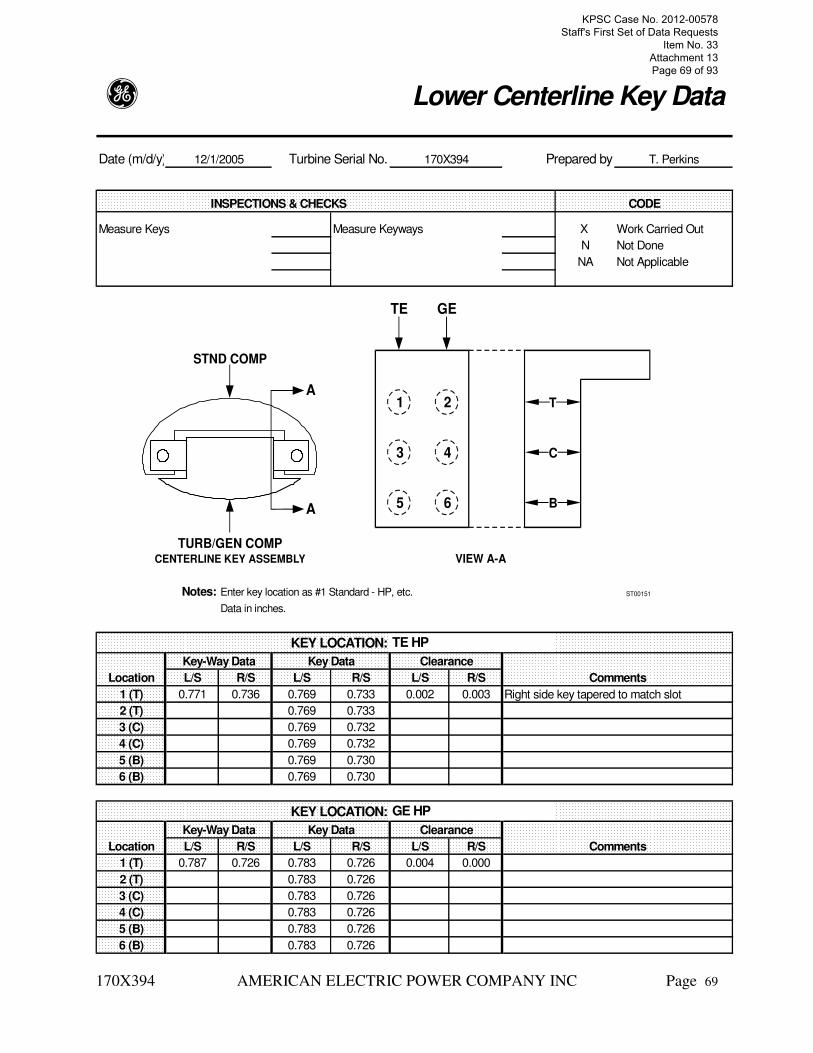
g Lower Centerline Key Data
Date (m/d/y) Turbine Serial No. Prepared by
INSPECTIONS & CHECKS CODE
Measure Keys Measure Keyways X Work Carried Out
N Not Done
NA Not Applicable
Notes: Enter key location as #1 Standard - HP, etc.
Data in inches.
KEY LOCATION:
Key-Way Data Key Data Clearance
Location L/S R/S L/S R/S L/S R/S Comments
1 (T) 0.771 0.736 0.769 0.733 0.002 0.003 Right side key tapered to match slot
2 (T) 0.769 0.733
3 (C) 0.769 0.732
4 (C) 0.769 0.732
5 (B) 0.769 0.730
6 (B) 0.769 0.730
KEY LOCATION:
Key-Way Data Key Data Clearance
Location L/S R/S L/S R/S L/S R/S Comments
1 (T) 0.787 0.726 0.783 0.726 0.004 0.000
2 (T) 0.783 0.726
3 (C) 0.783 0.726
4 (C) 0.783 0.726
5 (B) 0.783 0.726
6 (B) 0.783 0.726
GE HP
12/1/2005 170X394 T. Perkins
TE HP
1
STND COMP
TURB/GEN COMPCENTERLINE KEY ASSEMBLY VIEW A-A
2
3
A
A
4
5 6
TE GE
T
C
B
ST00151
KPSC Case No. 2012-00578 Staff's First Set of Data Requests
Item No. 33 Attachment 13 Page 69 of 93

170X394 AMERICAN ELECTRIC POWER COMPANY INC Page 70
g Upper Centerline Key Data
Date (m/d/y) Turbine Serial No. Prepared by
INSPECTIONS & CHECKS CODE
Measure Keys Measure Keyways X Work Carried Out
N Not Done
NA Not Applicable
Notes: Enter key location as #1 Standard - HP, etc.
Data in inches.
KEY LOCATION:
Key-Way Data Key Data Clearance
Location L/S R/S L/S R/S L/S R/S Comments
1 (T) 0.758 0.742 0.756 0.740 0.002 0.002
2 (T) 0.758 0.742 0.756 0.740 0.002 0.002
3 (C) 0.758 0.742 0.756 0.740 0.002 0.002
4 (C) 0.758 0.742 0.756 0.740 0.002 0.002
5 (B) 0.758 0.742 0.756 0.740 0.002 0.002
6 (B) 0.758 0.742 0.756 0.740 0.002 0.002
KEY LOCATION:
Key-Way Data Key Data Clearance
Location L/S R/S L/S R/S L/S R/S Comments
1 (T)
2 (T)
3 (C)
4 (C)
5 (B)
6 (B)
12/2/2005 170X394 T. Perkins
TE HP
1
STND COMP
TURB/GEN COMPCENTERLINE KEY ASSEMBLY VIEW A-A
2
3
A
A
4
5 6
TE GE
T
C
B
ST00151
KPSC Case No. 2012-00578 Staff's First Set of Data Requests
Item No. 33 Attachment 13 Page 70 of 93

170X394 AMERICAN ELECTRIC POWER COMPANY INC Page 71
Upper(a)
g Radial Rotor Position
Date:(m/d/y) 12/1/2005 Turbine Serial No. 170X394 Prepared by T. Perkins
As Found As Charted Final
LOCATION Tops-Off At Assembly Tops-On
T1 Oil Bore 10.002 10.002 9.978 10.025 9.993 10.016
9.985 10.006 10.000
N1 G1 0.000 0.004 0.766 0.760 0.002 0.000
0.003 0.743 -0.009
N3 G5 0.000 0.003 0.774 0.779 0.004 0.000
-0.023 0.750 -0.016
T2 Oil Bore 10.006 10.010 9.978 10.033 9.986 10.028
10.003 10.012 10.022
Comments:
KPSC Case No. 2012-00578 Staff's First Set of Data Requests
Item No. 33 Attachment 13 Page 71 of 93
170X394 AMERICAN ELECTRIC POWER COMPANY INC Page 72
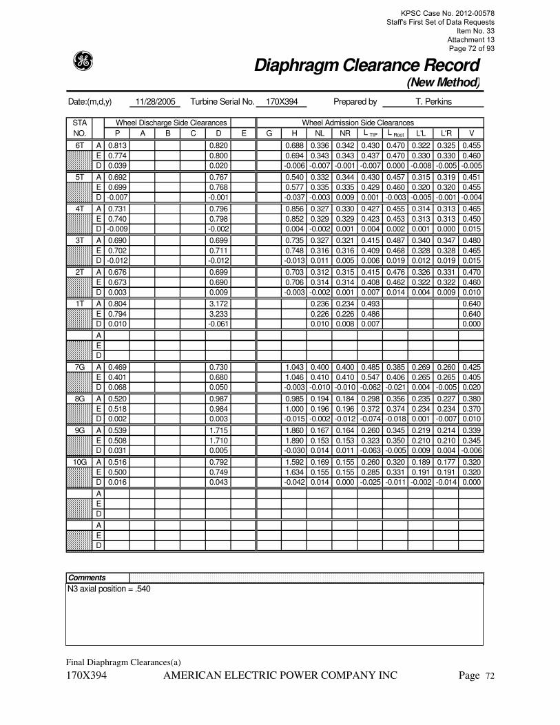
g Diaphragm Clearance Record(New Method)
Date:(m,d,y) 11/28/2005 Turbine Serial No. 170X394 Prepared by T. Perkins
STA Wheel Discharge Side Clearances Wheel Admission Side Clearances
NO. P A B C D E G H NL NR L TIP L Root L'L L'R V
6T A 0.813 0.820 0.688 0.336 0.342 0.430 0.470 0.322 0.325 0.455
E 0.774 0.800 0.694 0.343 0.343 0.437 0.470 0.330 0.330 0.460
D 0.039 0.020 -0.006 -0.007 -0.001 -0.007 0.000 -0.008 -0.005 -0.005
5T A 0.692 0.767 0.540 0.332 0.344 0.430 0.457 0.315 0.319 0.451
E 0.699 0.768 0.577 0.335 0.335 0.429 0.460 0.320 0.320 0.455
D -0.007 -0.001 -0.037 -0.003 0.009 0.001 -0.003 -0.005 -0.001 -0.004
4T A 0.731 0.796 0.856 0.327 0.330 0.427 0.455 0.314 0.313 0.465
E 0.740 0.798 0.852 0.329 0.329 0.423 0.453 0.313 0.313 0.450
D -0.009 -0.002 0.004 -0.002 0.001 0.004 0.002 0.001 0.000 0.015
3T A 0.690 0.699 0.735 0.327 0.321 0.415 0.487 0.340 0.347 0.480
E 0.702 0.711 0.748 0.316 0.316 0.409 0.468 0.328 0.328 0.465
D -0.012 -0.012 -0.013 0.011 0.005 0.006 0.019 0.012 0.019 0.015
2T A 0.676 0.699 0.703 0.312 0.315 0.415 0.476 0.326 0.331 0.470
E 0.673 0.690 0.706 0.314 0.314 0.408 0.462 0.322 0.322 0.460
D 0.003 0.009 -0.003 -0.002 0.001 0.007 0.014 0.004 0.009 0.010
1T A 0.804 3.172 0.236 0.234 0.493 0.640
E 0.794 3.233 0.226 0.226 0.486 0.640
D 0.010 -0.061 0.010 0.008 0.007 0.000
A
E
D
7G A 0.469 0.730 1.043 0.400 0.400 0.485 0.385 0.269 0.260 0.425
E 0.401 0.680 1.046 0.410 0.410 0.547 0.406 0.265 0.265 0.405
D 0.068 0.050 -0.003 -0.010 -0.010 -0.062 -0.021 0.004 -0.005 0.020
8G A 0.520 0.987 0.985 0.194 0.184 0.298 0.356 0.235 0.227 0.380
E 0.518 0.984 1.000 0.196 0.196 0.372 0.374 0.234 0.234 0.370
D 0.002 0.003 -0.015 -0.002 -0.012 -0.074 -0.018 0.001 -0.007 0.010
9G A 0.539 1.715 1.860 0.167 0.164 0.260 0.345 0.219 0.214 0.339
E 0.508 1.710 1.890 0.153 0.153 0.323 0.350 0.210 0.210 0.345
D 0.031 0.005 -0.030 0.014 0.011 -0.063 -0.005 0.009 0.004 -0.006
10G A 0.516 0.792 1.592 0.169 0.155 0.260 0.320 0.189 0.177 0.320
E 0.500 0.749 1.634 0.155 0.155 0.285 0.331 0.191 0.191 0.320
D 0.016 0.043 -0.042 0.014 0.000 -0.025 -0.011 -0.002 -0.014 0.000
A
E
D
A
E
D
Comments
N3 axial position = .540
Final Diaphragm Clearances(a)
KPSC Case No. 2012-00578 Staff's First Set of Data Requests
Item No. 33 Attachment 13 Page 72 of 93

170X394 AMERICAN ELECTRIC POWER COMPANY INC Page 73
g Packing Clearances &Wear Measurements
Date:(m,d,y) 11/28/2005 Turbine Serial No. 170X394 Prepared by T. Perkins
Data Final Turbine Section HP /RH
(As Found/Final)
Ring/ Axial Radial Packing Ring Segments Height (Ht) (Mils)
Stage Fig. (Mils) (Mils) Left Top Right Bottom Left
No. No. X Y Left Right 1 2 3 4 5 6 7 8 9 10 11 12
N1G1 295 562 38 32
N1G2 291 567 34 28
N1G3 291 565 16 18
N1G4 298 566 18 20
N1G5 291 567 20 15
N1G6 297 577 24 22
N1 G7 290 570 24 19
N2G1 249 329 60 40 Note: Tops-on change moves N2 15 mils to the right
N2G2 243 305 64 37
N2G3 250 299 60 34
N2G4 240 310 68 38
N2G5 251 301 68 37
N2G6 240 307 67 35
N2G7 236 315 68 35
N3G1 198 209 13 13
N3G2 197 213 13 14
N3G3 191 227 17 40
N3G4 181 235 32 29
N3G5 247 165 25 36
Fin
al N Packing Clearances(a)
KPSC Case No. 2012-00578 Staff's First Set of Data Requests
Item No. 33 Attachment 13 Page 73 of 93

170X394 AMERICAN ELECTRIC POWER COMPANY INC Page 74
g Spill Strip & Packing Clearance
Date:(m/d/y) 11/28/2005 Turbine Serial No. 170X394 Prepared by T. Perkins
STAGE Radial Clearances Axial Clearances
NO. M Z-1L Z-1R Z-2L Z-2R WL WR RL RR X Y Z-3 Z-4 XA Fig.
6T A 0.280 0.032 0.036 0.039 0.045 0.045 0.050 0.027 0.028 0.285 0.562 0.681 0.129 1
E 0.250 0.030 0.030 0.030 0.030 0.040 0.040 0.025 0.025 0.296 0.556 0.653 0.115
D 0.030 0.002 0.006 0.009 0.015 0.005 0.010 0.002 0.003 -0.011 0.006 0.028 0.014
5T A 0.275 0.039 0.044 0.040 0.047 0.050 0.050 0.024 0.029 0.275 0.563 0.288 0.117 1
E 0.250 0.030 0.030 0.030 0.030 0.040 0.040 0.025 0.025 0.296 0.556 0.306 0.115
D 0.025 0.009 0.014 0.010 0.017 0.010 0.010 -0.001 0.004 -0.021 0.007 -0.018 0.002
4T A 0.275 0.040 0.041 0.039 0.045 0.042 0.046 0.028 0.030 0.290 0.563 0.296 0.119 5
E 0.250 0.030 0.030 0.030 0.030 0.040 0.040 0.025 0.025 0.296 0.556 0.311 0.115
D 0.025 0.010 0.011 0.009 0.015 0.002 0.006 0.003 0.005 -0.006 0.007 -0.015 0.004
3T A 0.275 0.035 0.031 0.035 0.033 0.040 0.041 0.030 0.024 0.295 0.549 0.292 0.210 5
E 0.250 0.030 0.030 0.030 0.030 0.040 0.040 0.025 0.025 0.296 0.556 0.316 0.175
D 0.025 0.005 0.001 0.005 0.003 0.000 0.001 0.005 -0.001 -0.001 -0.007 -0.024 0.035
2T A 0.277 0.037 0.035 0.037 0.038 0.042 0.040 0.030 0.024 0.278 0.564 0.281 0.133 5
E 0.250 0.030 0.030 0.030 0.030 0.040 0.040 0.025 0.025 0.296 0.557 0.321 0.137
D 0.027 0.007 0.005 0.007 0.008 0.002 0.000 0.005 -0.001 -0.018 0.007 -0.040 -0.004
1T A 0.250 0.060 0.046 0.070 0.058 0.359
E 0.229 0.050 0.050 0.060 0.060 0.365
D 0.021 0.010 -0.004 0.010 -0.002 -0.006
7T A 0.067 0.048
E 0.050 0.050
D 0.017 -0.002
7G A 0.275 0.060 0.041 0.051 0.034 0.067 0.045 0.073 0.049 0.251 0.300 0.196 0.157 2
E 0.250 0.040 0.040 0.040 0.040 0.050 0.050 0.055 0.055 0.238 0.299 0.213 0.146
D 0.025 0.020 0.001 0.011 -0.006 0.017 -0.005 0.018 -0.006 0.013 0.001 -0.017 0.011
8G A 0.310 0.063 0.042 0.069 0.045 0.082 0.053 0.180 0.238 0.172 2
E 0.250 0.040 0.040 0.050 0.050 0.060 0.060 0.156 0.256 0.197
D 0.060 0.023 0.002 0.019 -0.005 0.022 -0.007 0.024 -0.018 -0.025
9G A 0.315 0.055 0.036 0.062 0.040 0.068 0.048 0.041 0.021 0.190 0.232 0.188 0.076 0.250 2
E 0.250 0.040 0.040 0.040 0.040 0.050 0.050 0.025 0.025 0.154 0.258 0.173 0.080 0.250
D 0.065 0.015 -0.004 0.022 0.000 0.018 -0.002 0.016 -0.004 0.036 -0.026 0.015 -0.004 0.000
10G A 0.300 0.060 0.030 0.064 0.026 0.065 0.040 0.045 0.015 0.190 0.215 0.127 0.192 2
E 0.250 0.040 0.040 0.040 0.040 0.050 0.050 0.025 0.025 0.155 0.257 0.140 0.189
D 0.050 0.020 -0.010 0.024 -0.014 0.015 -0.010 0.020 -0.010 0.035 -0.042 -0.013 0.003
A
E
D
A
E
D
Comments:
Note: .015 tops on movement in the reheat to the right. HP diaphragm movement .005 left.
KPSC Case No. 2012-00578 Staff's First Set of Data Requests
Item No. 33 Attachment 13 Page 74 of 93

170X394 AMERICAN ELECTRIC POWER COMPANY INC Page 75
g Spill Strip & Packing Clearance(Special)
Date:(m/d/y) 11/19/2005 Turbine Serial No. 170X394 Prepared by T. Perkins
STAGE Radial Clearances Axial Clearances
NO. Z-5L Z-5R R'L R'R X' Y' Fig.
6T A 0.021 0.029 1
E 0.020 0.020
D
5T A 0.022 0.030 1
E 0.020 0.020
D
4T A 0.024 0.028 0.056 0.051 NA 5
E 0.020 0.020 0.045 0.045 0.331
D
3T A 0.021 0.020 0.055 0.051 NA 5
E 0.020 0.020 0.045 0.045 0.331
D
2T A 0.026 0.022 0.055 0.047 NA 5
E 0.020 0.020 0.045 0.045 0.331
D
1T A
E
D
N2 G1 A 0.091 0.076 NA 6
E 0.065 0.065 0.333
D
N2 G3 A 0.084 0.060 NA 6
E 0.065 0.065 0.334
D
8G A 0.079 0.051 2
E 0.050 0.050
D
9G A 0.069 0.046 2
E 0.050 0.050
D
10G A 2
E
D
A
E
D
A
E
D
Comments:
Anti-whirl teeth are not like clearance dwg. No place to measure axial clearance.
KPSC Case No. 2012-00578 Staff's First Set of Data Requests
Item No. 33 Attachment 13 Page 75 of 93

g GE Energy Services
BEARINGS
170X394 AMERICAN ELECTRIC POWER COMPANY INC Page 76
Thrust Bearing
Assembly;
The thrust bearing was disassembled and inspected. The plates and seal rings were in
good condition and were re-used. Taper checks and flatness checks were performed on
the plates. New shims were machined for rotor position and thrust clearance. The thrust
ball was pinch checked and torque checked. The ball was scraped to achieve 85%
contact. A 2 mil shim was added to the saddle to achieve 1 mils loose fit and torque of
1300 ft-lbs.
Turbine Journal Bearing
Assembly; T1, T2
The T1 and T2 bearings were sent to the Pittsburgh Service Center for inspection and
reconditioning. The pads were rebabbitted to restore correct radial position and bored for
clearance to the rotor. New anti-rotation pins were installed. New upper rocker plates
were installed due to wear in the pin holes. (The existing pads were re-used, these are an
old modified rocker plate design which is obsolete.) The T1 bearing was bored to 16.016.
T2 was bored to 16.991. NOTE: These bearings are the original joint feed design, and
have not been modified to the individual pad feed type.
Consider obtaining new design bearing pads for the next HP/RH turbine inspection. New
design pads have replaceable anti-rotation pin inserts in the upper pads.
Oil Deflector
Assembly; T1, T2
The T1 and T2 oil deflectors were found rubbed and packed with coal dust. Both were
retoothed by AEP and aligned at assembly.
KPSC Case No. 2012-00578 Staff's First Set of Data Requests
Item No. 33 Attachment 13 Page 76 of 93

170X394 AMERICAN ELECTRIC POWER COMPANY INC Page 77
g Thrust BearingStraddle
Date(m/d/y) 11/26/2005 Turbine Serial No. 170X394 Prepared by T. Kudas
INSPECTIONS & CHECKS CODE
Ball Contact Check X Runner Inspection X X Work Carried Out
Ball Pinch Check X Wear Device Inspection N Not Done
Ball Torque Check X Screens and Orifices NA Not Applicable
Parallelism Check X Thermocouples Calib. C See Comments
Thrust Plate Inspection X Seal Rings Inspection X V Visual Inspection
Babbitt Inspection X MP Mag. Particle
UT Ultrasonic
PT Penetrant
THRUST BEARING DATA
"A" Shim .563"
"B" Plate 1.249"
"C" Shim .415"
"D" Plate 1.262"
"E" Casing 11.496"
"T" Total 14.985"
"F" Rotor 15.007"
THRUST CLEARANCE
Clearance (F minus T) .022"
Clearance (By float) .022"
Difference .000"
Stack Check ����
RUNOUT (mils TIL)
G BALL TORQUE
H Ball Diam. Inches
Reading 1300 Ft-Lb
Check
SEAL RING CLEARANCES
Turbine End Generator End
0° 90° Out of Round 0° 90° Out of Round
Seal Diameter (J) 15.009" 15.010" .001" 15.011" 15.005" .006"
Rotor Diameter (K) 15.000" 15.000" 15.000" 15.000"
Clearance .009" .010" .011" .005"
Comments
2 mil shim was added at assembly for 1 mil loose pinch.
A C
B D
G
TURBINEEND
GENERATOREND
K
J
H
ST00081
E
T
F
CL
Thrust Bearing(a)
KPSC Case No. 2012-00578 Staff's First Set of Data Requests
Item No. 33 Attachment 13 Page 77 of 93

170X394 AMERICAN ELECTRIC POWER COMPANY INC Page 78
g Thrust Bearing Independently Mounted - Tapered Land
Date(m,d,y) 9/23/2005 Turbine Serial No. 170X394 Prepared by T. Perkins
Axial Location
Gen
(Turb or Gen End)
Joint Orientation
Vert
(Vert or Horiz)
LAND TAPER
Position/Land 1 2 3 4 5 6 7 8 9 10 11 12
A 0 0 0 0 0 0 0 0 0 0
B -2 -2 -1 -2 -2 -1 -1 -1 -1 -2
OD C -5 -5 -4 -5 -6 -5 -5 -4 -4 -6
D -8 -8 -8 -8 -9 -8 -9 -8 -8 -9
E -12 -12 -12 -11 -13 -12 -12 -11 -12 -13
F 0 0 -1 -1 0 0 -1 -1 0 0
G -2 -2 -2 -2 -2 -2 -2 -3 -2 -2
MEAN H -5 -6 -6 -6 -5 -5 -6 -7 -6 -6
J -9 -10 -10 -9 -9 -9 -9 -10 -10 -10
K -14 -14 -14 -13 -14 -13 -14 -14 -14 -14
L -1 -1 -2 -1 -1 -1 -1 -1 -1 -1
M -2 -3 -4 -3 -2 -2 -2 -3 -3 -2
ID N -7 -7 -7 -7 -7 -6 -6 -7 -8 -6
P -10 -11 -11 -11 -10 -10 -10 -11 -11 -10
Q -14 -15 -16 -15 -15 -14 -15 -16 -16 -15
LAND HAS TC
(Yes or No)
PERCENT *
*Actual width of land (flat) in percent of total land width.
Comments
ST00098
Runner
Rotation
10% TotalLand Width
Outside Diam.of Babbitt
Flat
Trailing EdgeInside Diam.
of Babbitt
Mean Diam.of Babbitt
Leading Edge Radius
Design Edge of Flat(approx. 10% of total
land width)F
LMNP
GHJK
D C B AE
Sketch in Joint Split(horizontal or vertical)and Land NumberSequence for DataListed Below. Use Toolbar.
Total Land Width
100%Active Land Length
75%
25%
50%
ShaftRotation
KPSC Case No. 2012-00578 Staff's First Set of Data Requests
Item No. 33 Attachment 13 Page 78 of 93

170X394 AMERICAN ELECTRIC POWER COMPANY INC Page 79
g Thrust Bearing Independently Mounted - Tapered Land
Date(m,d,y) 9/23/20005 Turbine Serial No. 170X394 Prepared by J. Groll
Axial Location
TE
(Turb or Gen End)
Joint Orientation
Vert
(Vert or Horiz)
LAND TAPER All readings are in mils
Position/Land 1 2 3 4 5 6 7 8 9 10 11 12
A 0 0 0 0 0 0 0 0 0 0
B -2 -2 -2 -2 -3 -3 -3 -3 -2 -1
OD C -5 -6 -5 -5 -6 -7 -6 -7 -4 -3
D -9 -9 -9 -8 -9 -10 -10 -10 -8 -7
E -12 -13 -12 -13 -12 -13 -13 -13 -11 -9
F 0 0 0 0 0 -2 -1 -1 -1 -1
G -2 -2 -2 -2 -3 -4 -4 -4 -2 -2
MEAN H -5 -6 -6 -6 -6 -8 -8 -8 -5 -5
J -10 -10 -10 -10 -10 -12 -11 -12 -9 -9
K -13 -14 -13 -13 -14 -15 -15 -15 -13 -12
L 0 -1 -1 -1 0 -3 -2 -2 -2 -1
M -2 -2 -2 -3 -2 -5 -4 -4 -2 -3
ID N -6 -6 -6 -7 -7 -9 -8 -8 -6 -6
P -10 -11 -12 -11 -12 -14 -13 -13 -10 -11
Q -14 -14 -14 -15 -15 -17 -17 -16 -14 -14
LAND HAS TC
(Yes or No)
PERCENT *
*Actual width of land (flat) in percent of total land width.
Comments
ST00097
Runner
Rotation10% TotalLand Width
Outside Diam.of Babbitt
Flat
Flat
Trailing Edge Inside Diam.of Babbitt
Mean Diam.of Babbitt
Leading Edge Radius
Design Edge of Flat(approx. 10% of total
land width)A
F
L M N P
G H JK
DCBE Shaft
Rotation
Sketch in Joint Split(horizontal or vertical)and Land NumberSequence for DataListed Below. Use Toolbar.
Total Land Width
100%Active Land Width
75%
25%
50%
KPSC Case No. 2012-00578 Staff's First Set of Data Requests
Item No. 33 Attachment 13 Page 79 of 93

170X394 AMERICAN ELECTRIC POWER COMPANY INC Page 80
T1 Oil Deflector Coal Dust Contamination
KPSC Case No. 2012-00578 Staff's First Set of Data Requests
Item No. 33 Attachment 13 Page 80 of 93

170X394 AMERICAN ELECTRIC POWER COMPANY INC Page 81
g Oil Deflector
Date(m,d,y) 10/16/2005 Turbine Serial No. 170X394 Prepared by B. Haglock
INSPECTIONS & CHECKS CODE
Teeth Inspected X Work Carried Out
Journals Inspected N Not Done
Drain Holes Inspected NA Not Applicable
Inspect for Rubs C See Comments
V Visual Inspection
All retoothed MP Mag. Particle
UT Ultrasonic
PT Penetrant
Location Oil Deflector Journal Clearance Condition
Number A-Dia B-Dia C-Dia Dia Average Min. Max. Comment
T-1 OB 18.527" 18.527" 18.527" 18.497" .030" .030" .030"
T-1 IB 18.528" 18.530" 18.529" 18.497" .032" .031" .033"
T-2 OB 18.024" 18.020" 18.025" 17.991" .032" .029" .034"
T-2 IB 18.024" 18.020" 18.024" 17.991" .032" .029" .033"
Comments:
A
B
B
A
C
C
Oil Deflectors Final(a)
KPSC Case No. 2012-00578 Staff's First Set of Data Requests
Item No. 33 Attachment 13 Page 81 of 93

170X394 AMERICAN ELECTRIC POWER COMPANY INC Page 82
g Oil DeflectorAlignment
Date (m,d,y) 12/2/2005 Turbine Serial No. 170X394 Prepared by T. Perkins
Deflector POSITION (Mils) CLEARANCE IDEAL POSITION
Location 1 2 3 4 5 6 Median Min. Max Top Bottom Sides
T1 14 8 14 14 20 14 14 8 20 19 9 14
T2 13 6 13 13 20 13 13 6 20 17 9 13
Comments
ST00381
2
OILDEFLECTOR
LEFT RIGHT
6
1
4
3
5
ROTOR
Oil Deflector Alignment(a)
KPSC Case No. 2012-00578 Staff's First Set of Data Requests
Item No. 33 Attachment 13 Page 82 of 93

g GE Energy Services
LUBRICATION SYSTEM
170X394 AMERICAN ELECTRIC POWER COMPANY INC Page 83
Main Oil Pump
Valve - Check;
The main oil pump check valve was disassembled and inspected. The stop nut was found
too low, causing the disk to hit the pipe when open. The nut was built up with weld per
customer procedure.
Main Oil Pump
Assembly;
The main shaft driven oil pump was inspected. The seal rings were mic'd and were in
good condition. The bearing had excess clearance and was rebabbitted by the customer.
The casing was removed during the outage and a new gasket was installed to allow
realignment. The casing was aligned transversely to the rotor after coupling alignment.
Elevation was good after bearing shim changes. The steady bearing was movement
checked and force checked and aligned at assembly.
KPSC Case No. 2012-00578 Staff's First Set of Data Requests
Item No. 33 Attachment 13 Page 83 of 93

170X394 AMERICAN ELECTRIC POWER COMPANY INC Page 84
g Main Oil PumpCentrifugal Pump, Double Suction
Date(m/d/y) 11/27/2005 Turbine Serial No. 170X394 Prepared by T. Perkins
INSPECTIONS & CHECKS CODE
Mechanical Condition V X Work Carried Out
Internal Clearances X N Not Done
Bearing Condition & NA Not Applicable
Clearance X C See Comments
Steady Bearing Force V Visual Inspection
and Movement Checks X MP Mag. Particle
UT Ultrasonic
PT Penetrant
Ring I.D. 5.379 Left .126
Shaft O.D. 5.371 Right .124
Clearance .008 Bottom
Ring I.D. 8.740 Left .133
Impeller O.D. 8.730 Right .132
Clearance .010 Bottom
Left .750
Right .750
Ring I.D. 8.742
Impeller O.D. 8.731 Left .797
Clearance .011 Right .797
Left .134
Bearing I.D. 5.318 Right .133
Sleeve O.D. 5.312 Bottom .128
Clearance .006
Left .003
Right .003
Bottom .002
Left
Right
STEADY BEARING FORCE CHECK Bottom
FORCE(lbs) MOVEMENT (inches)
500 Comments:
1000
1500
2500
3000
SLIPS 2700#
MOP Final(a)
KPSC Case No. 2012-00578 Staff's First Set of Data Requests
Item No. 33 Attachment 13 Page 84 of 93

g GE Energy Services
TURNING GEAR
170X394 AMERICAN ELECTRIC POWER COMPANY INC Page 85
Turning Gear
Rod; Engagement
The turning gear toggle mechanism is not centered in its travel. This results in lower
spring force holding it engaged, and the angle is just barely adequate to hold it
disengaged.
The turning gear engagement mechanism should be inspected and repaired next
opportunity.
KPSC Case No. 2012-00578 Staff's First Set of Data Requests
Item No. 33 Attachment 13 Page 85 of 93

g GE Energy Services
STANDARDS
170X394 AMERICAN ELECTRIC POWER COMPANY INC Page 86
Front Standard
Assembly;
Rusted surfaces were found in the front standard and mid-standard. This could indicate
water in the lube oil, or condensation from extended periods with the lube oil off during
sectionalized maintenance.
Lube oil condition should be frequently monitored for water content to prevent rusting of
oil side components.
Mid Standard
Guard; A Coupling
While installing “A” coupling balance weights, an excessive amount of oil was spraying
from the coupling guard. Possibly the orifice is missing from the spray line.
Investigate excessive "A" coupling oil spray next inspection. Check spray line orifice.
KPSC Case No. 2012-00578 Staff's First Set of Data Requests
Item No. 33 Attachment 13 Page 86 of 93

g GE Energy Services
CONTROL SYSTEM
170X394 AMERICAN ELECTRIC POWER COMPANY INC Page 87
TSI
Detector; Thrust Position
The thrust position detector meter was set in the wrong direction at assembly, resulting in
the position shifting from negative to more negative.
The thrust position detector should be readjusted to position the meter at zero when the
rotor is centered in the thrust travel.
TSI
Instrumentation; Key Phaser
Prior to start-up, the key phaser was not functioning when the unit was placed on turning
gear. Investigation showed the notch in a different axial location than the removed rotor.
The probe was moved about 1" toward the generator to line up with the notch. Also,
during start-up, the key phaser became erratic at times. Customer personnel made
changes to the electrical connections to correct the problem.
TSI
Probe; T2 Right
During start-up, the 2X vibration probe failed. The connections were changed to the spare
probe.
The key-phaser and #2 bearing vibration probe problems should be investigated and
corrected next opportunity.
KPSC Case No. 2012-00578 Staff's First Set of Data Requests
Item No. 33 Attachment 13 Page 87 of 93

g GE Energy Services
ALIGNMENT & CLEARANCE OVERVIEW
170X394 AMERICAN ELECTRIC POWER COMPANY INC Page 88
A GE Laser Alignment Specialist performed a tops-on, tops-off laser alignment of the steam
path. The line was fixed in each bolt-on packing casing for the tops-on, tops-off, so all
movement is relative to the packing casing bores. During disassembly, titewire checks and
distortion checks showed the packing casings in good alignment with the outer shell, so the
lower halves were not removed this outage. The final tops-off line was set to compensate for
existing distortion in the packing casings, and the shell was aligned to the rotor after coupling
alignment to match these setpoints. (N1 was smaller vertically by .016. N3 was smaller vertically
by .040. Reroundable packing was adjusted to correct for N3 distortion. The N1 distortion was
minimal enough to use standard hook diameter packing.) The bolt-on packing casing bores were
measured in both the tops-off, and tops-on shell bolted condition. No significant change in
distortion was measured. A large change in internal component position was seen from tops-off
to tops-on. The vertical movement of the components in the inner shell was in the range of .008
to .026 in the upward direction. The HP diaphragms moved about .005 to the left. The N2 and
reheat diaphragms moved about .015 to the right. The out-of-plane upper inner shell joint
probably contributed to this large lateral movement.
At disassembly, the generator end of the inner shell was found about .025 higher than the turbine
end with respect to the outer shell joint. This condition had to be duplicated at assembly to
achieve the expected float on the axial locating fit. Radial alignment of the shell bores was also
good in this condition.
Comparing tops-off shell keys to gaps at disassembly showed the left side keys larger than the
gaps by an additional .012 than the right side. Optical checks of the lower outer shell joint also
showed the left side higher than the right by about .035. Optical and laser checks showed the
lower shell four corners in plane, with only a 2 mil twist. (4 mils low at TE left with respect to
other three corners.) This was corrected with final keys. The building keys were machined to
make the key vs gap difference the same on all four corners, keeping the joint in plane and
making it more level left to right, and matching the levelness with existing running keys. From
this point, all shell key changes were made equal left to right. Final tops-off keys were sized to
position the shell 10 mils higher than tops-on so the upper spill strips would not land on top of
the bucket covers when the shells were in the unbolted condition.
During assembly, the #3 bearing was moved to the left to close up a large face opening at "B"
coupling. (This large face opening was not seen at the disassembly coupling check.) This was
done prior to the HP assembly, so the HP rotor was installed temporarily before the inner shell
was installed to check the "A" coupling alignment. This confirmed the expected HP bearing side
moves to correct the face and rim. The bearings were moved to the left based on this check and
the shell was moved to match prior to installing the rotor in the steam path. The bearings were
also raised to correct elevation at this time. However, coupling checks with upper components on
showed the "A" face open now on the right. Shim changes were made to correct the alignment,
KPSC Case No. 2012-00578 Staff's First Set of Data Requests
Item No. 33 Attachment 13 Page 88 of 93

g GE Energy Services
ALIGNMENT & CLEARANCE OVERVIEW
170X394 AMERICAN ELECTRIC POWER COMPANY INC Page 89
but the full face correction was not realized. Based on inconsistent lateral face alignment at the
couplings, it appears that the standards are moving laterally over time, back and forth, possibly
with ambient condition changes.
Axial and radial clearances were approved by GE Engineering. All clearances were close to
design except axial packing clearances in the reheat and at N3. The "X" clearances were
progressively larger toward the generator from N2. No rotor packing land machining was done
on the rotor. All bucket machining was based on the first stage wheel. Since wheel clearances
and HP axial packing clearances were good, the existing rotor lands must be off drawing. (Rotor
shorter.) Also, the N3 G5 "X" clearance is 1/16" larger than the other N3 grooves due to an
original rotor machining deviation.
KPSC Case No. 2012-00578 Staff's First Set of Data Requests
Item No. 33 Attachment 13 Page 89 of 93

g GE Energy Services
STARTUP COMMENTS
170X394 AMERICAN ELECTRIC POWER COMPANY INC Page 90
The unit was first rolled 12/17/05, and tripped at about 200 rpm due to noise at the "C" coupling.
The coupling cover was removed and a long bolt was found in the coupling guard rubbing the
generator end windage covers. While the unit was down for this repair, tube leaks were found in
the boiler. Boiler repairs were completed and the unit was rolled again 12/21/05. The unit had to
be tripped several times below running speed due to high #4 bearing vibration. With the unit at
speed, varying vibration data indicated rubs in the 2nd reheat. The unit was rolled and
synchronized 12/22/05, still with high #4 bearing vibration, varying from 6 to 9 mils. Load was
increased to 360 MW. T4 bearing was still in the 7 to 8 mil range, T2 was at 6 mils. The unit was
shut down 12/23 for balance shots in the "A" and "B" couplings. The "B" coupling had the
expected effects, but the "A" coupling showed a larger effect angle than expected. The unit was
loaded to 660 MW and was removed from service 12/25/05 due to boiler tube leaks. The
previous "A" coupling shot was rotated and a couple shot was installed in LP A. This reduced T2
and T4 to about 3.5 mils. Future trim shots were planned in the "A" and "B" couplings. (See
attached data sheet.)
KPSC Case No. 2012-00578 Staff's First Set of Data Requests
Item No. 33 Attachment 13 Page 90 of 93

170X394 AMERICAN ELECTRIC POWER COMPANY INC Page 91
g Mitchell #2 Vibration Data Sheet
Date(m/d/y) 1/4/2006 Turbine Serial No. 170X394 Prepared by T. Perkins
1X 2X A COUPLING 3X 4X B COUPLING 5X 6X
DATE, TIME BRG BRG TURB END GEN END BRG BRG TURB END GEN END BRG BRG
LOAD/SPEED FILTER AMP DEG AMP DEG AMP DEG AMP DEG AMP DEG AMP DEG AMP DEG AMP DEG AMP DEG AMP DEG
12/23/05, 8:45 OUT 1.6 6.4 4.5 7.7 4.1 2.5
356 MW IN 1.5 284 6 39 8.9 270 7.5 260 4.5 33 7.6 136 9.5 0 9.5 5 4 108 2.2 302
12/23/05,17:00 OUT Added 12 oz @ 245 degrees in "A" cplg
Balance Shot IN Added 18 oz @ 300 degrees in "B" cplg
12/24/05, 8;20 OUT 1.8 5.3 3.2 4.7 2.9 3.2
335 MW IN 1.7 204 5.1 355 6.7 230 5.7 220 3.1 349 4.5 135 5 345 5 0 2.8 93 3 263
12/25/05, 3:33 OUT 1 5.5 2.8 5.2 2.6 3.6
660 MW IN 0.9 312 5.3 322 8.5 215 5.3 200 2.6 335 5 151 5.4 0 5.5 15 2.6 90 3.5 251
12/27/05,12:00 OUT Rotated previous "A" cplg shot from 245 to 205 degrees
Balance Shot IN Added 12.5 oz @ 225 degrees TE of LPA; added 12.5 oz @ 45 degrees GE of LPA
1/4/06, 13:02 OUT 0.7 3.4 1.8 3.6 1.7 1.7
681 MW IN 0.5 4 3.3 335 5.9 230 2.5 190 1.6 342 3.4 121 4.5 325 3.8 355 1.6 84 1.3 270
OUT
IN
OUT
IN
OUT
IN
Rotor Critical Speeds -
Frequency Scan -
Equipment Used - B/N - Brgs; IRD - Cplgs
Equipment Lag Angle -
Zero Ref Mark Color -
Inlet Oil Temp -
Comments:
Note: Phase angles are raw data. Key phaser is 45L. IRD data on couplings read at right horizontal joint.
Mitchell Vibration(a)
KPSC Case No. 2012-00578 Staff's First Set of Data Requests
Item No. 33 Attachment 13 Page 91 of 93

170X394 AMERICAN ELECTRIC POWER COMPANY INC Page 92
g Mitchell #2 Vibration Data Sheet
Date(m/d/y) 1/4/2006 Turbine Serial No. 170X394 Prepared by T. Perkins
C COUPLING 7X 8X D COUPLING 9X 10X 12X 13X
DATE, TIME TURB END GEN END BRG BRG TURB END GEN END BRG BRG BRG BRG
LOAD/SPEED FILTER AMP DEG AMP DEG AMP DEG AMP DEG AMP DEG AMP DEG AMP DEG AMP DEG AMP DEG AMP DEG
12/23/05, 8:45 OUT 0.8 1.5 1.8 3.2 0.7 2
356 MW IN 0.8 225 3 230 0.6 331 1.5 232 5 130 3 100 1.6 21 2.8 73 0.3 271 0.8 106
12/23/05,17:00 OUT Added 12 oz @ 245 degrees in "A" cplg
Balance Shot IN Added 18 oz @ 300 degrees in "B" cplg
12/24/05, 8;20 OUT 0.8 2 1.9 3.2 0.7 2
335 MW IN 1.8 155 3.3 205 0.5 303 1.8 243 5.7 130 3.5 115 1.8 352 2.6 60 0.2 270 0.8 105
12/25/05, 3:33 OUT 1.4 1.3 2.9 3.7 0.7 1.7
660 MW IN 1.9 130 2.9 185 1.2 268 1.1 237 5.3 140 2.8 125 2.8 4 3.2 56 0.2 274 0.8 113
12/27/05,12:00 OUT Rotated previous "A" cplg shot from 245 to 205 degrees
Balance Shot IN Added 12.5 oz @ 225 degrees TE of LPA; added 12.5 oz @ 45 degrees GE of LPA
1/4/06, 13:02 OUT 0.6 1.3 2.8 3.5 0.6 1.5
681 MW IN 0.1 350 2.2 220 0.4 325 1.1 239 4.6 125 2.5 100 2.7 16 3.1 55 0.2 249 0.7 114
OUT
IN
OUT
IN
OUT
IN
Rotor Critical Speeds -
Frequency Scan -
Equipment Used - B/N - Brgs; IRD - Cplgs
Equipment Lag Angle -
Zero Ref Mark Color -
Inlet Oil Temp -
Comments:
Mitchell Vibration(b)
KPSC Case No. 2012-00578 Staff's First Set of Data Requests
Item No. 33 Attachment 13 Page 92 of 93

g GE Energy Services
APPENDIX
170X394 AMERICAN ELECTRIC POWER COMPANY INC Page 93
KPSC Case No. 2012-00578 Staff's First Set of Data Requests
Item No. 33 Attachment 13 Page 93 of 93


