FOR YOUR SAFETYPLEASE READ THESE INSTRUCTIONS CAREFULLYAND RETAIN THEM FOR FUTURE USE.
OWNER’S MANUAL
SC100VAIR COMPRESSOR
PAGE 2
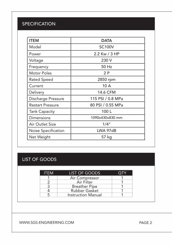
SPECIFICATION
ITEM DATA
Model SC100V
Power 2.2 Kw / 3 HP
Voltage 230 V
Frequency 50 Hz
Motor Poles 2 P
Rated Speed 2850 rpm
Current 10 A
Delivery 14.6 CFM
Discharge Pressure 115 PSI / 0.8 MPa
Restart Pressure 80 PSI / 0.55 MPa
Tank Capacity 100 L
Dimensions 1090x430x830 mm
Air Outlet Size 1/4”
Noise Specification LWA 97dB
Net Weight 57 kg
LIST OF GOODS
ITEM LIST OF GOODS QTY1 Air Compressor 12 Air Filter 13 Breather Pipe 14 Rubber Gasket 15 Instruction Manual 1
WWW.SGS-ENGINEERING.COM
PAGE 3
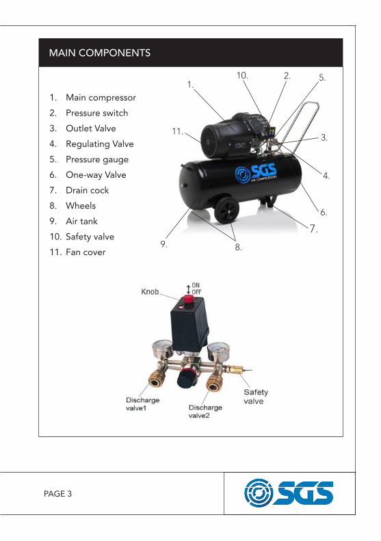
MAIN COMPONENTS
1. Main compressor
2. Pressure switch
3. Outlet Valve
4. Regulating Valve
5. Pressure gauge
6. One-way Valve
7. Drain cock
8. Wheels
9. Air tank
10. Safety valve
11. Fan cover
1.2.
3.
4.
5.
6.
7.
8.9.
10.
11.
PAGE 4
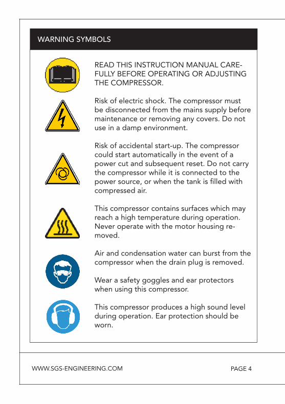
WARNING SYMBOLS
READ THIS INSTRUCTION MANUAL CARE-FULLY BEFORE OPERATING OR ADJUSTING THE COMPRESSOR.
Risk of electric shock. The compressor must be disconnected from the mains supply before maintenance or removing any covers. Do not use in a damp environment.
Risk of accidental start-up. The compressor could start automatically in the event of a power cut and subsequent reset. Do not carry the compressor while it is connected to thepower source, or when the tank is filled with compressed air.
This compressor contains surfaces which may reach a high temperature during operation. Never operate with the motor housing re-moved.
Air and condensation water can burst from the compressor when the drain plug is removed.
Wear a safety goggles and ear protectors when using this compressor.
This compressor produces a high sound level during operation. Ear protection should be worn.
WWW.SGS-ENGINEERING.COM
PAGE 5
TRAINING: Prior to use, all users must become familiar with the
instructions given in this manual. In particular, become familiar with
the ON/OFF control for stopping the compressor in the event of an
emergency.
ALWAYS USE EYE PROTECTION: When operating the air com-
pressor, always use eye protection such as goggles, and make sure
that other people in the work area are also using eye protection.
Eye protectors must provide protection from flying particles both
from the front and from the side.
PROTECT YOUR HEARING: Hearing protection should be worn
when operating this compressor, use ear plugs or ear defenders.
NEVER TOUCH MOVING PARTS: Never place your hand near
any moving parts on the air compressor or operate with the covers
removed.
PROTECT YOUR SELF AGAINST ELECTRIC SHOCK: Never oper-
ate the air compressor in wet or damp locations.
DRESS PROPERLY: Loose clothing or jewellery may be caught in
moving parts. Always tie long hair back, and wear suitable clothing.
SAFETY PRECAUTIONS
PAGE 6
KEEP VISITORS/CHILDREN AWAY: Do not allow visitors/children
to handle the air compressor or attachments and ensure that any
people in the work area are suitably dressed.
KEEP THE WORK AREA CLEAN: Cluttered areas mean accidents,
so clear the work area of all unnecessary tools, debris and furniture.
DO NOT TOUCH HOT SURFACES: During operation, the motor,
connections, compressor body, cylinder head and tubes may get
hot, do not touch.
DO NOT DIRECT AN AIR STREAM AT THE BODY: Do not direct
the air stream at people or animals, as injury may result. Com-
pressed air can cause soft tissue damage and propel dirt and other
particles at high speed.
BREATHING AIR: This compressor should not be used to supply
breathing quality air. Never use it as breathing apparatus.
STAY ALERT: Watch what you are doing, use common sense, and
do not operate the air compressor when you are tired. The air
compressor should not be used if you are under the influence of
alcohol, drugs or any medication that makes you drowsy.
SAFETY PRECAUTIONS
WWW.SGS-ENGINEERING.COM
PAGE 7
DISCONNECT THE AIR COMPRESSOR: Always disconnect the air
compressor from the mains power supply and decompress before
performing maintenance, changing any parts and when not in use.
MAINS POWER CABLE PRECAUTIONS: Never pull on the cable
when removing the plug from the mains socket, or lift the compres-
sor by the mains cable.
AVOID UNINTENTIONAL STARTING: When connecting the air
compressor to the mains supply make sure the red button on top of
the air compressor is in the OFF (down) position.
STORE THE AIR COMPRESSOR PROPERLY: When not in use the
air compressor should be stored in a secure, dry place out of the
reach of children. Always lock up the storage area.
MAINTAIN THE AIR COMPRESSOR WITH CARE: If the air com-
pressor is damaged in any way, have it repaired by a qualified
engineer.
DO NOT USE EXTENSION LEADS: Using extension leads can
cause your compressor motor to burn out. Only use extension
hoses.
SAFETY PRECAUTIONS
PAGE 8
DISPOSAL INFORMATION: The air compressor should be disposed
of in a safe an environmentally friendly manner. Contact your local
Council for disposal assistance.
DO NOT WELD TO THE PRESSURE VESSEL: Do not weld or
modify the pressure vessel in any manner.
SAFETY PRECAUTIONS
WWW.SGS-ENGINEERING.COM

PAGE 9
ASSEMBLY
- Use a spanner to attach the wheels to the compressor.- Use the washers and spring washer in the positions shown.
Insert the support foot into the position shown.
PAGE 10
PREPARATION FOR STARTING
1. Check all nuts and bolts.
Make sure all loosened parts
are tightened before starting.
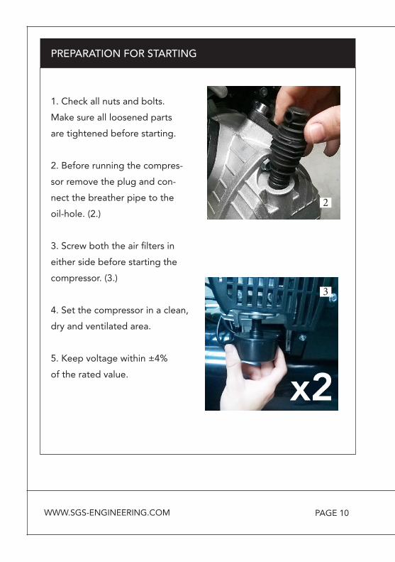
2. Before running the compres-
sor remove the plug and con-
nect the breather pipe to the
oil-hole. (2.)
3. Screw both the air filters in
either side before starting the
compressor. (3.)
4. Set the compressor in a clean,
dry and ventilated area.
5. Keep voltage within ±4%
of the rated value.
2
3
WWW.SGS-ENGINEERING.COM
PAGE 11
PREPARATION FOR STARTING
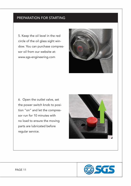
5. Keep the oil level in the red
circle of the oil glass sight win-
dow. You can purchase compres-
sor oil from our website at:
www.sgs-engineering.com
6. Open the outlet valve, set
the power switch knob to posi-
tion “on” and let the compres-
sor run for 10 minutes with
no load to ensure the moving
parts are lubricated before
regular service.
PAGE 12
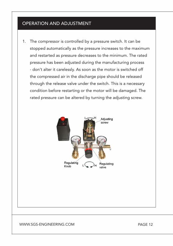
1. The compressor is controlled by a pressure switch. It can be
stopped automatically as the pressure increases to the maximum
and restarted as pressure decreases to the minimum. The rated
pressure has been adjusted during the manufacturing process
- don’t alter it carelessly. As soon as the motor is switched off
the compressed air in the discharge pipe should be released
through the release valve under the switch. This is a necessary
condition before restarting or the motor will be damaged. The
rated pressure can be altered by turning the adjusting screw.
OPERATION AND ADJUSTMENT
WWW.SGS-ENGINEERING.COM

PAGE 13
OPERATION AND ADJUSTMENT
PRESSURE GAUGES
There are two pressure gauges on the compressor.
1. The pressure gauge on the RIGHT shows the current pres-sure in the reservoir tank.
2. The pressure gauge on the LEFT shows the ‘user set’ outlet pressure. This can be adjusted using the regulator.
2. The output pressure
of compressed air can be
adjusted by the regulat-
ing valve. Grip the regula-
tion valve knob and turn it
clockwise to increase the
pressure.
PAGE 14
OPERATION AND ADJUSTMENT
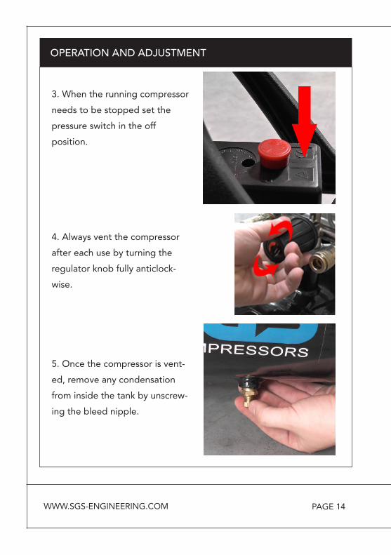
3. When the running compressor
needs to be stopped set the
pressure switch in the off
position.
4. Always vent the compressor
after each use by turning the
regulator knob fully anticlock-
wise.
5. Once the compressor is vent-
ed, remove any condensation
from inside the tank by unscrew-
ing the bleed nipple.
WWW.SGS-ENGINEERING.COM
PAGE 15
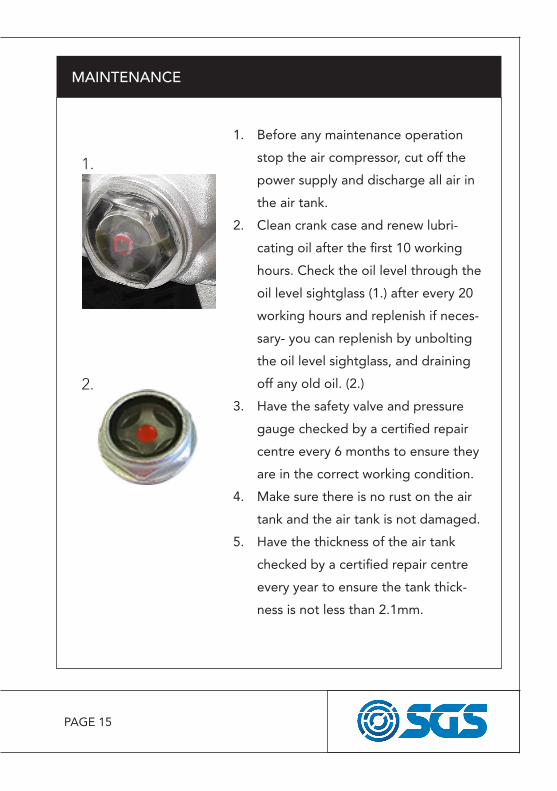
1. Before any maintenance operation
stop the air compressor, cut off the
power supply and discharge all air in
the air tank.
2. Clean crank case and renew lubri-
cating oil after the first 10 working
hours. Check the oil level through the
oil level sightglass (1.) after every 20
working hours and replenish if neces-
sary- you can replenish by unbolting
the oil level sightglass, and draining
off any old oil. (2.)
3. Have the safety valve and pressure
gauge checked by a certified repair
centre every 6 months to ensure they
are in the correct working condition.
4. Make sure there is no rust on the air
tank and the air tank is not damaged.
5. Have the thickness of the air tank
checked by a certified repair centre
every year to ensure the tank thick-
ness is not less than 2.1mm.
MAINTENANCE
1.
2.

PAGE 16
MAINTENANCE
CLEAN THE AIR FILTERS (MONTHLY)
The air filters must be examined month-ly, more often in dusty conditions:
1. Remove the filter covers from the compressor.
2. Remove the filter covers from the filters.
3. Remove the filters from the filter covers.
4. Clean the sponge and both the filters cover using a soft brush.If necessary, the filters can be care-fully cleaned in warm soapy water.Rinse and let the filters dry com-pletely before refitting.
5. Make sure that the filters and filter covers are replaced into position. If the filters are damaged, you must replace them.
WWW.SGS-ENGINEERING.COM

PAGE 17
MAINTENANCE
CHECK THE NON-RETURN VALVE (EVERY 6 MONTHS)
If the reservoir pressure decreases for no apparent reason, it is possible that the non-return valve is leaking. To check: 1. Make sure that the reservoir
is not under pressure and the compressor is switched OFF.
2. Examine the non-return valve, and replace the gasket and valve if necessary.
PAGE 18
THERMAL RESET SWITCH
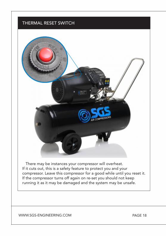
There may be instances your compressor will overheat. If it cuts out, this is a safety feature to protect you and your compressor. Leave this compressor for a good while until you reset it. If the compressor turns off again on re-set you should not keep running it as it may be damaged and the system may be unsafe.
WWW.SGS-ENGINEERING.COM
PAGE 19
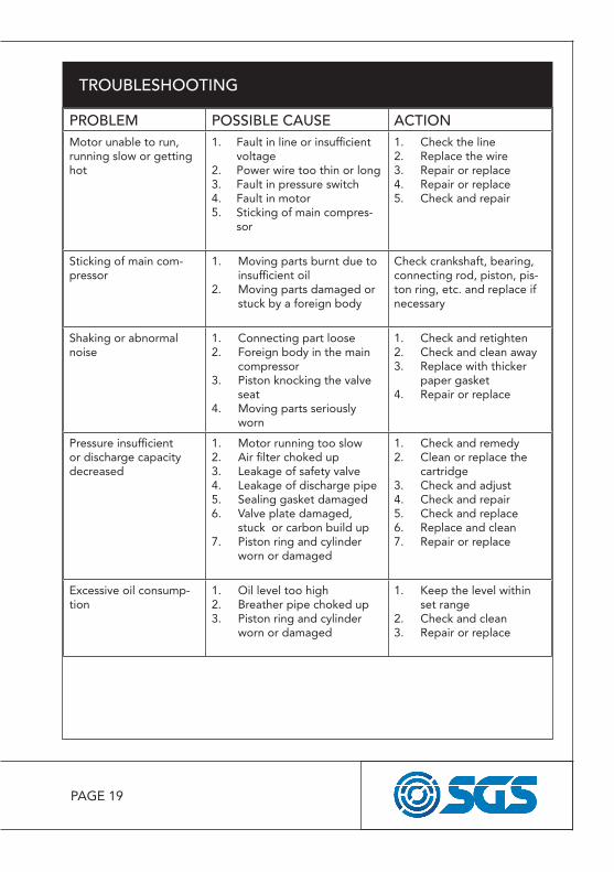
TROUBLESHOOTING
PROBLEM POSSIBLE CAUSE ACTIONMotor unable to run, running slow or getting hot
1. Fault in line or insufficient voltage
2. Power wire too thin or long3. Fault in pressure switch4. Fault in motor5. Sticking of main compres-
sor
1. Check the line2. Replace the wire3. Repair or replace4. Repair or replace5. Check and repair
Sticking of main com-pressor
1. Moving parts burnt due to insufficient oil
2. Moving parts damaged or stuck by a foreign body
Check crankshaft, bearing,connecting rod, piston, pis-ton ring, etc. and replace ifnecessary
Shaking or abnormal noise
1. Connecting part loose2. Foreign body in the main
compressor3. Piston knocking the valve
seat4. Moving parts seriously
worn
1. Check and retighten2. Check and clean away3. Replace with thicker
paper gasket4. Repair or replace
Pressure insufficient or discharge capacity decreased
1. Motor running too slow2. Air filter choked up3. Leakage of safety valve4. Leakage of discharge pipe5. Sealing gasket damaged6. Valve plate damaged,
stuck or carbon build up7. Piston ring and cylinder
worn or damaged
1. Check and remedy2. Clean or replace the
cartridge3. Check and adjust4. Check and repair5. Check and replace6. Replace and clean7. Repair or replace
Excessive oil consump-tion
1. Oil level too high2. Breather pipe choked up3. Piston ring and cylinder
worn or damaged
1. Keep the level within set range
2. Check and clean3. Repair or replace
PAGE 20
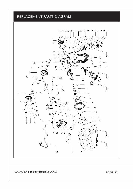
REPLACEMENT PARTS DIAGRAM
WWW.SGS-ENGINEERING.COM
PAGE 21
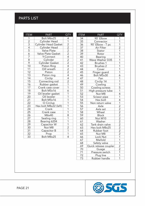
PARTS LIST
ITEM PART QTY1 Bolt M6x25 42 Cylinder Head 13 Cylinder Head Gasket 24 Cylinder Head 25 Valve Plate 26 Valve Plate Gasket 27 Y-Connect 48 Cylinder 29 Cylinder Gasket 210 Piston Ring 411 Oill wreath 212 Piston 213 Piston ring 414 Circlip 415 Connecting rod 216 Rubber gasket 117 Crank case cover 118 Bolt M5x16 619 Oil leveler gasket 120 Oil leveler 121 Bolt M5x16 122 O Circlup 123 Hex bolt M8x22 (left) 124 Crank 125 Crank case 126 M6x40 827 Sealing ring 128 Bearing 6204 129 Capacitor W 130 Nut M8 231 Capacitor B 132 Prop 133 Bolt M8x25 4
ITEM PART QTY34 90’ Elbow 135 Connector 136 90’ Elbow - T pc 137 Air Filter 238 Stator 139 Rotor 140 Bearing 141 Wave Washer D35 142 Brushes 1 143 Brushes 2 144 Cover 145 Finger guard 146 Bolt M5x30 647 Fan 148 Circlip 14 149 Cowling 150 Cowling screws 551 High pressure tube 152 Nut M8 453 Scissor pipe 154 Hex bolt 455 Non return valve 156 Axle 257 Axle set 258 Wheel 259 Block 260 Nut M10 261 Washer 262 Tank drain valve 263 Hex bolt M8x25 264 Rubber foot 265 Nut M8 266 Lock Nut 167 Maifold 168 Safety valve 169 Quick release coupler 270 Guage 271 Pressure switch 172 Plug line 173 Rubber handle 1

EC Declaration of Conformity
This is an important document and should be retained
MANUFACTURER’S NAME:
TYPE OF EQUIPMENT:
PART NUMBER:
I, the undersigned, hereby declare that the equipment specified above con-forms to the above European Communities Directive(s) and Standard(s).
PLACE:
DATE: (Signature)
Robert WyattCompany Secretary
Derby, UK
24th JUNE 2017
SGS Engineering (UK) Ltd
SGS Engineering (UK) LtdWest Side Park
RayneswayDerby, DE21 7AZ
Air Compressor
SC100V
EN 1012-1:2010 AfPS GS 2014:01 PAKEN 61000-6-1:2007EN 61000-6-3:2007/A1:2011Machinery Directive 2006/42/ECLow Voltage Directive 2014/35/EUElectromagnetic Compatibility 2014/30/EU Simple Pressure Vessel Directive 2009/105/EC Directive of Emission 2010/26/ECDirective of EU Noise 2005/88/EC
Rated Voltage 230V~Rated Power 2200WRated Frequency 50HzProtection Class IProtection Degree IP20Max. Working Pressure 0.8MPa; 0.8MPa 1.0MPa; 0.8MPaRemark Indoors only
PARAMETERS:
APPLICATION OF EC COUNCIL DIRECTIVES / STANDARD:


