
Catalog
2010
Magnecraft®
Solid State Relays
Courtesy of Steven Engineering, Inc.-230 Ryan Way, South San Francisco, CA 94080-6370-Main Office: (650) 588-9200-Outside Local Area: (800) 258-9200-www.stevenengineering.com
2
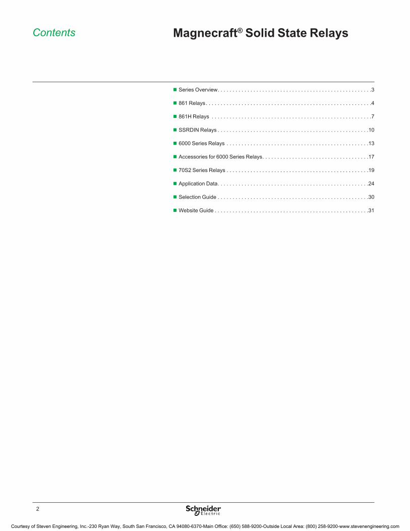
Contents Magnecraft® Solid State Relays
Series Overview � � � � � � � � � � � � � � � � � � � � � � � � � � � � � � � � � � � � � � � � � � � � � � � � � � � � �3
861 Relays � � � � � � � � � � � � � � � � � � � � � � � � � � � � � � � � � � � � � � � � � � � � � � � � � � � � � � � � �4
861H Relays � � � � � � � � � � � � � � � � � � � � � � � � � � � � � � � � � � � � � � � � � � � � � � � � � � � � � � �7
SSRDIN Relays � � � � � � � � � � � � � � � � � � � � � � � � � � � � � � � � � � � � � � � � � � � � � � � � � � � �10
6000 Series Relays � � � � � � � � � � � � � � � � � � � � � � � � � � � � � � � � � � � � � � � � � � � � � � � � �13
Accessories for 6000 Series Relays � � � � � � � � � � � � � � � � � � � � � � � � � � � � � � � � � � � � �17
70S2 Series Relays � � � � � � � � � � � � � � � � � � � � � � � � � � � � � � � � � � � � � � � � � � � � � � � � �19
Application Data � � � � � � � � � � � � � � � � � � � � � � � � � � � � � � � � � � � � � � � � � � � � � � � � � � � �24
Selection Guide � � � � � � � � � � � � � � � � � � � � � � � � � � � � � � � � � � � � � � � � � � � � � � � � � � � �30
Website Guide � � � � � � � � � � � � � � � � � � � � � � � � � � � � � � � � � � � � � � � � � � � � � � � � � � � � �31
Courtesy of Steven Engineering, Inc.-230 Ryan Way, South San Francisco, CA 94080-6370-Main Office: (650) 588-9200-Outside Local Area: (800) 258-9200-www.stevenengineering.com
3
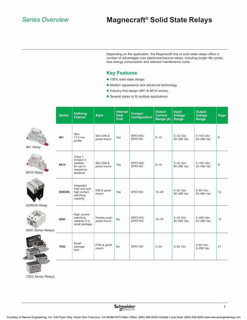
Series Defining Feature Style
Internal Heat Sink
Contact Configuration
Output Current Range (A)
Input Voltage Range
Output Voltage Range
Page
861 Slim 17�5 mm profile
Slim DIN & panel mount Yes SPST-NO;
SPST-NC 8–15 3–32 Vdc;90–280 Vac
3–150 Vdc;24–480 Vac 6
861H
Class 1, Division 2 certified for use in hazardous locations
Slim DIN & panel mount Yes SPST-NO;
SPST-NC 8–15 3–32 Vdc;90–280 Vac
3–150 Vdc;24–480 Vac 9
SSRDIN
Integrated heat sink and high current switching capacity
DIN & panel mount Yes SPST-NO 10–45 4–32 Vdc;
90–280 Vac0–60 Vdc;24–660 Vac 12
6000High current switching capacity in a small package
Hockey puck-panel mount No SPST-NO;
DPST-NO 10–75 3–32 Vdc;90–280 Vac
3–200 Vdc;24–480 Vac 15
70S2Small package size
PCB & panel mount No SPST-NO 3–25 3–32 Vdc 3–60 Vdc;
8–280 Vac 21
Series Overview Magnecraft® Solid State Relays
Depending on the application, the Magnecraft line of solid state relays offers a number of advantages over electromechanical relays, including longer life cycles, less energy consumption and reduced maintenance costs�
Key Features100% solid state design �
Modern appearance and advanced technology �
Industry first design (861 & 861H series) �
Several styles to fit multiple applications �
861 Relay
861H Relay
SSRDIN Relay
6000 Series Relays
70S2 Series Relays
Courtesy of Steven Engineering, Inc.-230 Ryan Way, South San Francisco, CA 94080-6370-Main Office: (650) 588-9200-Outside Local Area: (800) 258-9200-www.stevenengineering.com
4
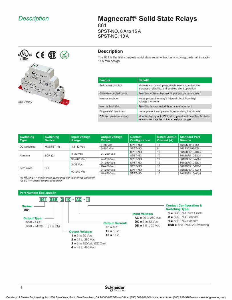
DescriptionThe 861 is the first complete solid state relay without any moving parts, all in a slim 17�5 mm design�
Switching Type
Switching Device
Input Voltage Range
Output Voltage Range
Contact Configuration
Rated Output Current (A)
Standard Part Number
DC switching MOSFET (1) 3�5–32 Vdc3–50 Vdc SPST-NO 15 861SSR115-DD3–150 Vdc SPST-NO 8 861SSR208-DD
Random SCR (2)3–32 Vdc 24–280 Vac
SPST-NO 10 861SSR210-DC-2SPST-NC 10 861SSR210-DC-4
90–280 Vac 24–280 Vac SPST-NO 10 861SSR210-AC-2
Zero cross SCR3–32 Vdc
24–280 Vac SPST-NO 10 861SSR210-DC-148–480 Vac SPST-NO 10 861SSR410-DC-1
90–280 Vac24–280 Vac SPST-NO 10 861SSR210-AC-148–480 Vac SPST-NO 10 861SSR410-AC-1
(1) MOSFET = metal oxide semiconductor field-effect transistor(2) SCR = silicon-controlled rectifier
Part Number Explanation
Series:861
Output Type:SSR = SCRSSR = MOSFET (DD Only)
Output Voltage: 1 = 3 to 50 Vdc2 = 24 to 280 Vac2 = 3 to 150 Vdc (DD Only)4 = 48 to 480 Vac
Output Current:08 = 8 A10 = 10 A15 = 15 A
Input Voltage:AC = 90 to 280 VacDC = 3 to 32 VdcDD = 3.5 to 32 Vdc
Contact Con�guration & Switching Type:
1 = SPST-NO, Zero Cross2 = SPST-NO, Random4 = SPST-NC, RandomNull = SPST-NO, DC Switching
Feature BenefitSolid state circuitry Involves no moving parts which extends product life,
increases reliability, and enables silent operation
Optically coupled circuit Provides isolation between input and output circuits
Internal snubber Helps protect the relay’s internal circuit from high voltage transients
Internal heat sink Provides factory-tested thermal management
Fingersafe® terminals Helps prevent an operator from touching live circuits
DIN and panel mounting Mounts directly onto DIN rail or panel and provides flexibility to accommodate last minute design changes
Description Magnecraft® Solid State Relays861SPST-NO, 8 A to 15 ASPST-NC, 10 A
861 Relay
Courtesy of Steven Engineering, Inc.-230 Ryan Way, South San Francisco, CA 94080-6370-Main Office: (650) 588-9200-Outside Local Area: (800) 258-9200-www.stevenengineering.com

5
Specifications (UL 508)Part Number 861SSR•••-DD 861SSR•••-DC-• 861SSR•••-AC-•
Input Characteristics Input Voltage Range 3�5–32 Vdc 3–32 Vdc 90–280 VacMust Release Voltage 1 Vdc 10 Vac Nominal Input Impedance Current regulator 16–25 kWTypical Input Current at 5 Vdc 12 mA 16 mA; 12 mA
(861SSR210-DC-4)12 mA
Reverse Polarity Protection Yes Yes N/A
Output CharacteristicsSwitching Device MOSFET SCR (2)
Switching Type DC switching Zero cross; Random
Contact Configuration SPST-NO SPST-NO; SPST-NC
Output Voltage Range 3–150 Vdc 24–480 Vac
Maximum Rate of Rise Off State Voltage (dv/dt) N/A 500 V/us; 350 V/us (861SSR410); 200 V/us (861SSR210-DC-4)
Output Current Range 8–15 A 10 A (rms)
Minimum Load Current–Maintain On 20 mA 50 mA
Non-Repetitive Surge Current (8�3 ms) 8 A: 35 A; 15 A: 50 A
500 A (rms)
Maximum rms Overload Current (1 s) 8 A: 17 A; 15 A: 24 A;
24 A (rms)
Maximum Off State Leakage Current 0�25 mA 10 mA (rms)
Typical On State Voltage Drop N/A 1�25 Vac (rms)
Maximum On State Voltage Drop 0�5 Vdc 1�6 Vac (rms)
Maximum On State Resistance 40 mW N/A
Maximum Turn-On Time 5 ms 8�3 ms
Maximum Turn-Off Time 5 ms 8�3 ms
Maximum I² T for Fusing N/A 1250 A²sec (861SSR210); 850 A²sec (861SSR410)
General CharacteristicsElectrical Life N/A for solid state relays
Thermal Resistance (Junction–Case) 8 A: 0�5 °C/W; 15 A: 1�4 °C/W
0�66 °C/W
Internal Heat Sink 4�0 °C/W
Dielectric Strength (Input–Output) 2500 V (rms) 4000 V (rms)
Dielectric Strength (Terminals–Chassis) 2500 V (rms)
Operating Temperature Range -30 °C–+ 80 °C (derating applies)
Storage Temperature Range -40 °C–+100 °C
Weight 127�1 g (4�1 oz)
Input Indication Green LED
Terminal Wire Capacity (Input and Output) 14 AWG (2�5 mm²) maximum
Terminal Screw Torque 7�1 lb-in (0�8 N•m) maximum
Safety Cover IP20
Agency Approvals UL Listed (E258297); CE (per IEC60947-4-2); CSA (168986); RoHS
Specifications Magnecraft® Solid State Relays861SPST-NO, 8 A to 15 ASPST-NC, 10 A
Courtesy of Steven Engineering, Inc.-230 Ryan Way, South San Francisco, CA 94080-6370-Main Office: (650) 588-9200-Outside Local Area: (800) 258-9200-www.stevenengineering.com

6
INPUT
+
INP
UT
OU
TP
UT
OUTPUTPOWER SOURCE
POWER SUPPLY
SSR
-
LOAD
(-) 18A2 (-)
(+) 15A1 (+)
MOSFET ONLY
0.56(14.2)
0.3
0.7(17.6)
0.2(5.0)
(6.9)
3.5
2.6
1.8(90)
(66.8)
(45.3) 1.4(35.6)
0.1
0.7
1.4
2.6 MAX.
(16.0)
(34.6)
(65.0)
0.20.6
(6)(15.8)
(3.4)
0.6(14.0)
1.4(35.2)
0.6(14.3)
0.1(1.7)
3.6(92.4)
0.2(5)
INPUT
OUTPUT
De-Rating Curves
AMBIENT TEMPERATURE IN °C
LOA
D C
UR
RE
NT
IN A
MP
ER
ES 14
16
12
10
8
6
4
2
13
15
11
9
7
5
3
1
0 10 20 30 40 50 60 70 80 905 15 25 35 45 55 65 75 85
Note: A minimum spacing of 17.5 mm (0.7 in) between adjacent 861 relays is required in order to acheive the maximum ratings.
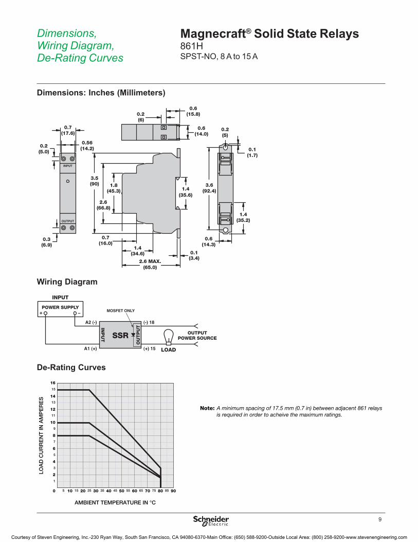
Dimensions, Wiring Diagram, De-Rating Curves
Magnecraft® Solid State Relays861SPST-NO, 8 A to 15 ASPST-NC, 10 A
Dimensions: Inches (Millimeters)
Wiring Diagram
Courtesy of Steven Engineering, Inc.-230 Ryan Way, South San Francisco, CA 94080-6370-Main Office: (650) 588-9200-Outside Local Area: (800) 258-9200-www.stevenengineering.com

7
DescriptionThe 861H is the first complete solid state relay approved for use in hazardous locations. Patent pending.
Switching Type
Switching Device
Input Voltage Range
Output Voltage Range
Contact Configuration
Rated Output Current (A)
Standard Part Number
DC switching MOSFET 3.5–32 Vdc3–50 Vdc SPST-NO 15 861HSSR115-DD3–150 Vdc SPST-NO 8 861HSSR208-DD
Zero cross SCR (2)
3–32 Vdc24–280 Vac SPST-NO 10 861HSSR210-DC-148–480 Vac SPST-NO 10 861HSSR410-DC-148–600 Vac SPST-NO 10 861HSSR610-DC-1
90–280 Vac24–280 Vac SPST-NO 10 861HSSR210-AC-148–480 Vac SPST-NO 10 861HSSR410-AC-148–600 Vac SPST-NO 10 861HSSR610-AC-1
Feature BenefitClass 1, Division 2 certification (1)
UL-approved relay for use in hazardous locations
Solid state circuitry Involves no moving parts, which extends product life, increases reliability, and enables silent operation
Optically coupled circuit Provides isolation between input and output circuits
Internal snubber Helps protect the relay’s internal circuit from high voltage transients
Internal heat sink Provides factory-tested thermal management
Fingersafe® terminals Helps prevent an operator from touching live circuits
DIN and panel mounting Mounts directly onto DIN rail or panel and provides flexibility to accommodate last minute design changes
(1) See page 30 for more information on Class 1, Division 2.
Class 1, Division 2 certification for use in hazardous locations.
(Temperature code: T5)
Part Number Explanation
Series:861H
Output Type:SSR = SCRSSR = MOSFET (DD Only)
Output Voltage: 1 = 3 to 50 Vdc2 = 24 to 280 Vac2 = 3 to 150 Vdc (DD Only)4 = 48 to 480 Vac6 = 48 to 600 Vac
Output Current:08 = 8 A10 = 10 A15 = 15 A
Input Voltage:AC = 90 to 280 VacDC = 3 to 32 VdcDD = 3.5 to 32 Vdc
Contact Con�guration & Switching Type:
1 = SPST-NO, Zero CrossNull = SPST-NO, DC Switching
Description Magnecraft® Solid State Relays861HSPST-NO, 8 A to 15 A
861H Relay
Courtesy of Steven Engineering, Inc.-230 Ryan Way, South San Francisco, CA 94080-6370-Main Office: (650) 588-9200-Outside Local Area: (800) 258-9200-www.stevenengineering.com

8
Specifications (UL 508)Part Number 861SSR•••-DD 861SSR•••-DC-• 861SSR•••-AC-•
Input Characteristics Input Voltage Range 3�5–32 Vdc 3–32 Vdc 90–280 VacMust Release Voltage 1 Vdc 10 Vac Nominal Input Impedance Current regulator 16–25 kWTypical Input Current at 5 Vdc 12 mA 16 mA; 12 mA
(861SSR210-DC-4)12 mA
Reverse Polarity Protection Yes Yes N/A
Output CharacteristicsSwitching Device MOSFET SCR (2)
Switching Type DC switching Zero cross; Random
Contact Configuration SPST-NO SPST-NO; SPST-NC
Output Voltage Range 3–150 Vdc 24–480 Vac
Maximum Rate of Rise Off State Voltage (dv/dt) 8 A: 3–150 V:15 A: 3–50 V
500 V/us; 350 V/us (861SSR410); 200 V/us (861SSR210-DC-4)
Output Current Range 8–15 A 10 A (rms)
Minimum Load Current–Maintain On 20 mA 50 mA
Non-Repetitive Surge Current (8�3 ms) 8 A: 35 A; 15 A: 50 A
500 A (rms)
Maximum rms Overload Current (1 s) 8 A: 17 A; 15 A: 24 A;
24 A (rms)
Maximum Off State Leakage Current 0�25 mA 10 mA (rms)
Typical On State Voltage Drop N/A 1�25 Vac (rms)
Maximum On State Voltage Drop 0�5 Vdc 1�6 Vac (rms)
Maximum On State Resistance 40 mW N/A
Maximum Turn-On Time 5 ms 8�3 ms
Maximum Turn-Off Time 5 ms 8�3 ms
Maximum I² T for Fusing N/A 1250 A²sec (861SSR210); 850 A²sec (861SSR410)
General CharacteristicsElectrical Life N/A for solid state relays
Thermal Resistance (Junction–Case) 8 A: 0�5 °C/W; 15 A: 1�4 °C/W
0�66 °C/W
Internal Heat Sink 4�0 °C/W
Dielectric Strength (Input–Output) 2500 V (rms) 4000 V (rms)
Dielectric Strength (Terminals–Chassis) 2500 V (rms)
Operating Temperature Range -30 °C–+ 80 °C (derating applies)
Storage Temperature Range -40 °C–+100 °C
Weight 127�1 g (4�1 oz)
Input Indication Green LED
Terminal Wire Capacity (Input and Output) 14 AWG (2�5 mm²) maximum
Terminal Screw Torque 7�1 lb-in (0�8 N•m) maximum
Safety Cover IP20
Agency Approvals Class 1, Division 2 (for hazardous locations); UL Recognized (E317746); RoHS
Specifications Magnecraft® Solid State Relays861HSPST-NO, 8 A to 15 A
Courtesy of Steven Engineering, Inc.-230 Ryan Way, South San Francisco, CA 94080-6370-Main Office: (650) 588-9200-Outside Local Area: (800) 258-9200-www.stevenengineering.com
9
Wiring Diagram
INPUT
+IN
PU
T
OU
TP
UT
OUTPUTPOWER SOURCE
POWER SUPPLY
SSR
-
LOAD
(-) 18A2 (-)
(+) 15A1 (+)
MOSFET ONLY
0.56(14.2)
0.3
0.7(17.6)
0.2(5.0)
(6.9)
3.5
2.6
1.8(90)
(66.8)
(45.3) 1.4(35.6)
0.1
0.7
1.4
2.6 MAX.
(16.0)
(34.6)
(65.0)
0.20.6
(6)(15.8)
(3.4)
0.6(14.0)
1.4(35.2)
0.6(14.3)
0.1(1.7)
3.6(92.4)
0.2(5)
INPUT
OUTPUT
De-Rating Curves
AMBIENT TEMPERATURE IN °C
LOA
D C
UR
RE
NT
IN A
MP
ER
ES 14
16
12
10
8
6
4
2
13
15
11
9
7
5
3
1
0 10 20 30 40 50 60 70 80 905 15 25 35 45 55 65 75 85
Note: A minimum spacing of 17.5 mm (0.7 in) between adjacent 861 relays is required in order to acheive the maximum ratings.
Dimensions, Wiring Diagram, De-Rating Curves
Magnecraft® Solid State Relays861HSPST-NO, 8 A to 15 A
Dimensions: Inches (Millimeters)
Courtesy of Steven Engineering, Inc.-230 Ryan Way, South San Francisco, CA 94080-6370-Main Office: (650) 588-9200-Outside Local Area: (800) 258-9200-www.stevenengineering.com

10
DescriptionThe SSRDIN relays offer a complete solid state package that is an energy-efficient, current switching alternative to standard electromechanical relays� Advantages include longer life cycles, less energy consumption, and reduced maintenance costs�
Switching Type Switching Device
Input Voltage Range
Output Voltage Range
Contact Configuration
Rated Output Current (A) Standard Part Number
DC switching MOSFET 4–32 Vdc 0–60 Vdc SPST-NO10 SSR310DIN-DC22 (1)20 SSR320DIN-DC22 (1)30 SSR330DIN-DC22 (1)
Zero cross SCR
4–32 Vdc 24–280 Vac SPST-NO10 SSR210DIN-DC2220 SSR220DIN-DC2230 SSR230DIN-DC22
3–32 Vdc 24–280 Vac SPST-NO 45 SSR245DIN-DC45
4–32 Vdc 48–660 Vac SPST-NO10 SSR610DIN-DC2220 SSR620DIN-DC2230 SSR630DIN-DC22
SPST-NO 45 SSR645DIN-DC45
90–280 Vac 24–280 Vac SPST-NO10 SSR210DIN-AC2220 SSR220DIN-AC2230 SSR230DIN-AC22
90–140 Vac 24–280 Vac SPST-NO 45 SSR245DIN-AC45
90–280 Vac 48–660 Vac SPST-NO10 SSR610DIN-AC2220 SSR620DIN-AC2230 SSR630DIN-AC22
SPST-NO 45 SSR645DIN-AC45
(1) No agency approvals on MOSFET versions
Feature BenefitSolid state circuitry Involves no moving parts
Optically coupled circuit Provides isolation between input and output circuits
Internal snubber Helps protect the relay’s internal circuit from high voltage transients
Internal heat sink Provides factory tested thermal management
Integrated chassis ground Simplifies system wiring
Fingersafe® terminals Helps prevent an operator from touching live circuits
DIN and panel mounting Increases functionality and ease of use and fits a variety of applications
Part Number Explanation
SeriesSSR
Output Voltage2 = SCR, 24 to 280 Vac3 = MOSFET, 0 to 60 Vdc
Current Rating10 = 10 A20 = 20 A30 = 30 A45 = 45 A
Input VoltageAC = 90 to 280 VacDC = 4 to 32 Vdc
Size22 = 22 mm width45 = 45 mm width
SSRDIN Relay
Description Magnecraft® Solid State RelaysSSRDINSPST-NO, 10 A to 45 A
Courtesy of Steven Engineering, Inc.-230 Ryan Way, South San Francisco, CA 94080-6370-Main Office: (650) 588-9200-Outside Local Area: (800) 258-9200-www.stevenengineering.com

11
Specifications (UL 508)Part Number SSR2••DIN-DC•• SSR3••DIN-DC22 SSR6••DIN-DC•• SSR2••DIN-AC•• SSR6••DIN-AC••
Input CharacteristicsInput Voltage Range 4–32 Vdc 90–280 Vac
Maximum Turn-On Voltage 4 Vdc 90 Vrms
Minimum Turn-Off Voltage 1 Vdc 10 Vrms
Typical Input Current 8–12 mA 9–11 mA 8–12 mA 2–4 mA
Output CharacteristicsOutput Type SCR MOSFET SCR
Switching Type Zero voltage DC switching Zero voltage
Output Voltage 24–280 Vac 0–60 Vdc 48–660 Vac 24–280 Vac 48–660 Vac
Load Current Range 10–45 A 10–30 A 10–45 A
Transient Over-Voltage 600 Vpk N/A 1200 Vpk 600 Vpk 1200 Vpk
Maximum Surge Current 10 A: 120 Apk; 20 A: 250 Apk; 30/45 A: 625 Apk (at 16�6 ms)
10 A: 30 Apk; 20 A: 60 Apk; 30 A: 90 Apk (at 10 ms)
625 Apk (at 16�6 ms)
10 A: 120 Apk; 20 A: 250 Apk; 30/45 A: 625 Apk (at 16�6 ms)
625 Apk (at 16�6 ms)
Maximum On-State Voltage Drop at Rated Current
1�6 Vpk 10 A: 0�2 Vpk; 20 A: 0�4 Vpk; 30 A: 0�5 Vpk
1�6 Vpk 1�6 Vpk 1�6 Vpk
Maximum I²t For Fusing, (8�3 ms)
10 A: 60 A²sec; 20 A: 260 A²sec; 30/45 A: 1620 A²sec
N/A 1620 A²sec 10 A: 60 A²sec; 20 A: 260 A²sec; 30/45 A: 1620 A²sec
1620 A²sec
Maximum Off-State Leakage Current at Rated Voltage
10 mA 0�1 mA 1 mA 10 mA 1 mA
Maximum Rate of Rise Off State Voltage (dv/dt)
500 V/us N/A 500 V/us
Maximum Response Time (On and Off)
1/2 cycle 1�0 ms 1/2 cycle
Maximum On State Resistance N/A 10 A: 20 mW; 20 A: 18 mW; 30 A: 16 mW
N/A
General CharacteristicsElectrical Life N/A for solid state relays
Operating Temperature Range -40–+80 °C (derating applies)
Storage Temperature Range -40–+125 °C
Weight 10/20/30 A: 272 g (9�6 oz); 45 A: 482 g (17 oz)
Input Indication Green LED
Encapsulation Thermally conductive epoxy
Input Terminal Screw Torque 10/20/30 A: 5�0-6�0 in lb (0�6-0�7 N•m); 45 A: 5�0-6�0 in lb (0�6-0�7 N•m)
Output Terminal Screw Torque 10/20/30 A: 5�0-6�0 in lb (0�6-0�7 N•m); 45 A: 10�0-15�0 in lb (1�1-1�7 N•m)
Mount Type DIN rail and panel mount
Agency Approvals UL Recognized (E258297) SCR output only; CSA (168986) SCR output only; CE (per IEC 60950 and 61000); RoHS
Specifications Magnecraft® Solid State RelaysSSRDINSPST-NO, 10 A to 45 A
Courtesy of Steven Engineering, Inc.-230 Ryan Way, South San Francisco, CA 94080-6370-Main Office: (650) 588-9200-Outside Local Area: (800) 258-9200-www.stevenengineering.com

12
Dimensions: Inches (Millimeters)
Wiring Diagram
De-Rating Curves
INPUT
+IN
PU
T
OU
TP
UT
OUTPUTPOWER SOURCE
POWER SUPPLY
SSR
-
LOAD
(-) 24 (-)
(+) 13 (+)
MOSFET ONLY
20
15
25
30
35
45
40
10
5
100 30 50 70 9020 40 60 80
Load Current vs Ambient Temperature (100% Duty Cycle)
LOA
D C
UR
REN
T IN
AM
PS
MAXIMUM AMBIENT TEMP. IN °C
SSRDIN 30 A
SSRDIN 45 A
SSRDIN 20 A
SSRDIN 10 A
0.89(22.6)0.88
(22.4)
1.79(45.5)
0.88(22.4)
MOUNTING HOLE0.17 (4.3) DIA.
3.44(87.4)
3.1(78.7)
2.51(63.7)
4.2(106.7)
3.1(78.7)0.88
(22.4)
0.44(11.2)
3.15(80.0)
3.53(89.7)
3.15(80.0)
2.61(66.2)
MOUNTING HOLE0.17 (4.3) DIA.
3.8(97.7)
22 mm 45 mm
INPUT
OUTPUT
INPUT
OUTPUT
a
100.39
22 mm
a 6 mm2
AWG 1010 mm2
AWG 84 mm2
AWG 12
input output45 mm
input output
Dimensions, Wiring Diagram, De-Rating Curves
Magnecraft® Solid State RelaysSSRDINSPST-NO, 10 A to 45 A
Courtesy of Steven Engineering, Inc.-230 Ryan Way, South San Francisco, CA 94080-6370-Main Office: (650) 588-9200-Outside Local Area: (800) 258-9200-www.stevenengineering.com

13
DescriptionThe 6000 Series solid state relays offer an energy-efficient, current switching alternative to standard electromechanical relays� Advantages include longer life cycles, less energy consumption, and reduced maintenance costs�
Switching Type Switching Device
Input Voltage Range
Output Voltage Range
Contact Configuration
Rated Output Current (A)
Standard Part Number
DC switching MOSFET 3.5–32 Vdc 3–200 Vdc SPST-NO12 6312AXXMDS-DC325 6325AXXMDS-DC340 6340AXXMDS-DC3
Zero cross
SCR
3–32 Vdc24–280 Vac SPST-NO
10 6210AXXSZS-DC325 6225AXXSZS-DC340 6240AXXSZS-DC350 6250AXXSZS-DC3
48–480 Vac SPST-NO25 6425AXXSZS-DC350 6450AXXSZS-DC3
90–280 Vac24–280 Vac SPST-NO
10 6210AXXSZS-AC9025 6225AXXSZS-AC9040 6240AXXSZS-AC9050 6250AXXSZS-AC9075 6275AXXSZS-AC90
48–480 Vac SPST-NO10 6410AXXSZS-AC9025 6425AXXSZS-AC90
Triac 3–32 Vdc24–280 Vac DPST-NO 10 6210BXXTZB-DC3*
48–480 VacSPST-NO 25 6425AXXTZB-DC3*DPST-NO 25 6425BXXTZB-DC3*
* Blade terminals.
Part Number Explanation
Series6000
Output Voltage2 = 24 to 280 Vac3 = 3 to 200 Vdc4 = 48 to 530 Vac
Current Rating10 = 10 A 40 = 40 A12 = 12 A 50 = 50 A25 = 25 A 75 = 75 A
Contact Con�gurationAXX = SPST-NOBXX = DPST-NO
Output TypeM = MOSFETS = SCRT = TRIAC
Switching TypeD = DC SwitchingZ = Zero Cross
Connection TypeB = Blade TerminalsS = Screw Terminals
Input VoltageAC90 = 90–280 VacDC3 = 3–32 Vdc
Feature BenefitSolid state circuitry Involves no moving parts
Optically coupled circuit Provides isolation between input and output circuits
Internal snubber Helps protect the relay’s internal circuit from high voltage transients
Fingersafe® terminals Helps prevent an operator from touching live circuits
6000 Series Relays
Description Magnecraft® Solid State Relays6000SPST-NO, 10 A to 75 ADPST-NO, 10 A to 25 A
Courtesy of Steven Engineering, Inc.-230 Ryan Way, South San Francisco, CA 94080-6370-Main Office: (650) 588-9200-Outside Local Area: (800) 258-9200-www.stevenengineering.com

14
Specifications (UL 508)Part Number 62••AXXSZS-AC90 64••AXXSZS-AC90 62••AXXSZS-DC3 64••AXXSZS-DC3
Input CharacteristicsControl Voltage Range 90–280 Vac (rms) 3–32 Vdc 4–32 VdcMaximum Turn-On Voltage 90 Vac (rms) 3 Vdc 4 VdcMinimum Turn-Off Voltage 10 Vac (rms) 1 VdcNominal Input Impedance 60 KW N/ATypical Input Current 2 mA at 120 V (rms), 4 mA at 240 V (rms) 10 mA at 12 Vdc 15 mA DC
Output CharacteristicsSwitching Device SCRSwitching Type Zero Cross
Contact Configuration SPST-NOOutput Current Range 10–75 A 10–25 A 10–50 A 25–50 AOutput Voltage Range (47–63 Hz) 24–280 Vac (rms) 48–530 Vac (rms) 24–280 Vac (rms) 48–530 Vac (rms)Transient Over-voltage 600 Vpk 1200 Vpk 600 Vpk 1200 VpkMaximum Off-State Leakage Current at Rated Voltage 10 mA (rms) 1 mA (rms)Minimum Off-State dv/dt at Maximum Rated Voltage 500 V/usMinimum Load Current 40 mA (rms) 150 mA (rms)Maximum Surge Current (16�6 ms) 10 A: 120 Apk;
25 A: 250 Apk; 40/50 A: 625 Apk; 75 A: 1000 Apk
10 A: 140 Apk; 25 A: 250 Apk
10 A: 120 Apk; 25 A: 250 Apk; 40/50 A: 625 Apk
25 A: 250 Apk; 50 A: 625 Apk
Maximum On-State Voltage Drop at Rated Current 1�6 V (rms) 1�7 V (rms) 1�6 V (rms)Maximum I²T for Fusing (8�3 ms) 10 A: 60 A²sec;
25 A: 260 A²sec; 40/50A: 1620 A²sec; 75A: 4150 A²sec
10 A: 81 A²sec; 25 A: 260 A²sec
10 A: 60 A²sec; 25 A: 260 A²sec; 40/50 A: 1620 A²sec
25 A: 260 A²sec; 50 A: 1620 A²sec
Minimum Power Factor (with Maximum Load) 0�5
General CharacteristicsElectrical Life N/A for solid state relaysMaximum Turn-On Time 10 ms 1/2 Cycle Maximum Turn-Off Time 40 ms 1/2 Cycle Thermal Resistance (Junction–Case) 10 A: 1�48 °C/W; 25 A: 1�02 °C/W; 40/50A: 0�63 °C/W; 75 A: 0�31 °C/WDielectric Strength, Input/Output/Base (50/60 Hz) 4000 Vac (rms)Minimum Insulation Resistance (at 500 Vdc) 1E+9 WMaximum Capacitance (Input/Output) 8 pFAmbient Operating Temperature Range -40–80 °C (derating applies)Ambient Storage Temperature Range -40–125 °C
Weight (typical) 86�5 g (3 oz)
Input Indication Green LED
Encapsulation Thermally conductive epoxy
Terminals Screw and saddle clamps furnished, unmounted
Recommended Terminal Screw Torque Range 6-32 Screws: 10 lb-in; 8-32 & 10-32 Screws: 20 lb-in (Screws dry without grease)
Safety Cover Yes
Wire Clamp Plates Yes
Agency Approvals UL Recognized (E258297); CE (per IEC 60950 and 61000); CSA (168986); RoHS
Specifications Magnecraft® Solid State Relays6000SPST-NO, 10 A to 75 ADPST-NO, 10 A to 25 A
Courtesy of Steven Engineering, Inc.-230 Ryan Way, South San Francisco, CA 94080-6370-Main Office: (650) 588-9200-Outside Local Area: (800) 258-9200-www.stevenengineering.com
15
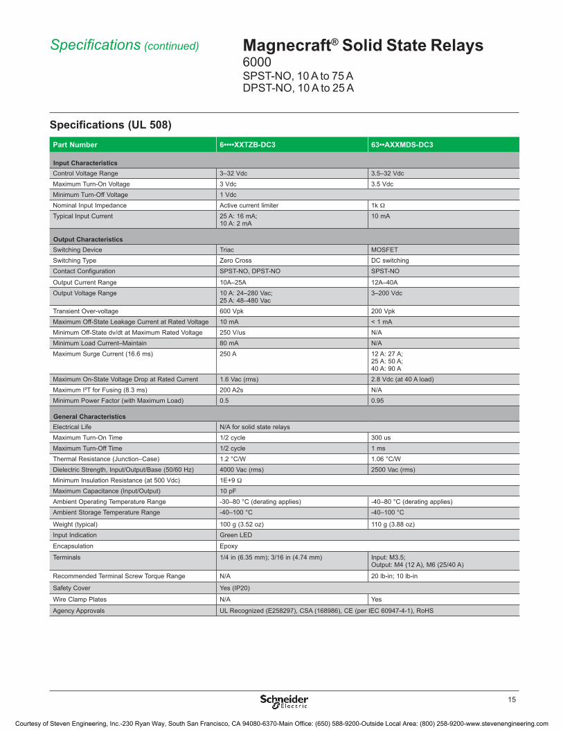
Specifications (UL 508)Part Number 6••••XXTZB-DC3 63••AXXMDS-DC3
Input CharacteristicsControl Voltage Range 3–32 Vdc 3�5–32 VdcMaximum Turn-On Voltage 3 Vdc 3�5 VdcMinimum Turn-Off Voltage 1 VdcNominal Input Impedance Active current limiter 1k WTypical Input Current 25 A: 16 mA;
10 A: 2 mA10 mA
Output CharacteristicsSwitching Device Triac MOSFETSwitching Type Zero Cross DC switchingContact Configuration SPST-NO, DPST-NO SPST-NO
Output Current Range 10A–25A 12A–40AOutput Voltage Range 10 A: 24–280 Vac;
25 A: 48–480 Vac3–200 Vdc
Transient Over-voltage 600 Vpk 200 VpkMaximum Off-State Leakage Current at Rated Voltage 10 mA < 1 mAMinimum Off-State dv/dt at Maximum Rated Voltage 250 V/us N/AMinimum Load Current–Maintain 80 mA N/AMaximum Surge Current (16�6 ms) 250 A 12 A: 27 A;
25 A: 50 A; 40 A: 90 A
Maximum On-State Voltage Drop at Rated Current 1�6 Vac (rms) 2�8 Vdc (at 40 A load)Maximum I²T for Fusing (8�3 ms) 200 A2s N/AMinimum Power Factor (with Maximum Load) 0�5 0�95
General CharacteristicsElectrical Life N/A for solid state relaysMaximum Turn-On Time 1/2 cycle 300 usMaximum Turn-Off Time 1/2 cycle 1 msThermal Resistance (Junction–Case) 1�2 °C/W 1�06 °C/WDielectric Strength, Input/Output/Base (50/60 Hz) 4000 Vac (rms) 2500 Vac (rms)Minimum Insulation Resistance (at 500 Vdc) 1E+9 WMaximum Capacitance (Input/Output) 10 pFAmbient Operating Temperature Range -30–80 °C (derating applies) -40–80 °C (derating applies)Ambient Storage Temperature Range -40–100 °C -40–100 °C
Weight (typical) 100 g (3�52 oz) 110 g (3�88 oz)Input Indication Green LED
Encapsulation Epoxy
Terminals 1/4 in (6�35 mm); 3/16 in (4�74 mm) Input: M3�5;Output: M4 (12 A), M6 (25/40 A)
Recommended Terminal Screw Torque Range N/A 20 lb-in; 10 lb-in
Safety Cover Yes (IP20)
Wire Clamp Plates N/A Yes
Agency Approvals UL Recognized (E258297), CSA (168986), CE (per IEC 60947-4-1), RoHS
Specifications (continued) Magnecraft® Solid State Relays6000SPST-NO, 10 A to 75 ADPST-NO, 10 A to 25 A
Courtesy of Steven Engineering, Inc.-230 Ryan Way, South San Francisco, CA 94080-6370-Main Office: (650) 588-9200-Outside Local Area: (800) 258-9200-www.stevenengineering.com

16
INPUT
+
INP
UT
OU
TP
UT
OUTPUTPOWER SOURCE
POWER SUPPLY
SSR
-
LOAD
(-) 14 (-)
(+) 23 (+)
MOSFET ONLY
02
10 A
Load Current (Arms)
Pow
er D
issi
patio
n
Bas
e P
late
Tem
p (°
C)
Ambient Temp. (°C)3 6 8 10 20 40 60 80
4120
115
110
8
123°C/W
5°C/W
7°C/W
9°C/W
NO HEATSINK
010
50 A
Load Current (Arms)
Pow
er D
issi
patio
n
Bas
e P
late
Tem
p (°
C)
Ambient Temp. (°C)20 30 40 50 20 40 60 80
20
120
100
90
40
60
110
NO HEATSINK
1°C/W
2°C/W
0.5°C/W
1.5°C/W
0
5
10
15
20
25
30
5
25 A
Load Current (Arms)
Pow
er D
issi
patio
n
Bas
e P
late
Tem
p (°
C)
Ambient Temp. (°C)10 15 20 25 20 40 60 80
120
110
100
95
NO HEATSINK
1°C/W
2°C/W3°C/W
015
75 A
Load Current (Arms)
Pow
er D
issi
patio
n
Bas
e P
late
Tem
p (°
C)
Ambient Temp. (°C)30 45 60 75 20 40 60 80
40
120
110
95
80
120
1000.3°C/W0.5°C/W
1°C/W
12 A MOSFET
25/40 A MOSFET
0
50
40
30
20
10
10 20 30 40 50 60 70 80Ambient Temp. (°C)
Load
Cur
rent
(Arm
s)
Mounted on heat sink with0.5 ºC/W thermal resistance
0
50
40
30
20
10
10 20 30 40 50 60 70 80Ambient Temp. (°C)
Load
Cur
rent
(Arm
s)
Mounted on heat sink with3.2 ºC/W thermal resistance
Mounted on heat sink with0.5 ºC/W thermal resistance
4.2 (0.163)
Terminal
Input
Output
Min. Max. 3.5
(0.138) 5
(0.197)6.35
(0.25)
10 max0.393
mmin
OUTPUT
Cu 75°Cmax. ambient25°C
0..50A 50..125A
1.4(35.9)
2.28(57.91)
1.74 (44.14)
1.7(43.42)
Blade TerminalsScrew Terminals
INPUT
OUTPUT
INPUT
OUTPUT
1.87(47.5)
1.74 (44.14)
0.41(10.5)
0.125 (3.2)
1 (-) 2 (+)
4 (-) 3 (+)
1 (-) 2 (+)
5 (-) 6 (+)
4 (-) 3 (+)
0.192 (4.9) DIA.
Side View(25 & 40 A MOSFET versions only)
Side View
Dimensions, Wiring Diagram, De-Rating Curves
Magnecraft® Solid State Relays6000SPST-NO, 10 A to 75 ADPST-NO, 10 A to 25 A
Dimensions: Inches (Millimeters)
Wiring Diagram
De-Rating Curves
Courtesy of Steven Engineering, Inc.-230 Ryan Way, South San Francisco, CA 94080-6370-Main Office: (650) 588-9200-Outside Local Area: (800) 258-9200-www.stevenengineering.com
17
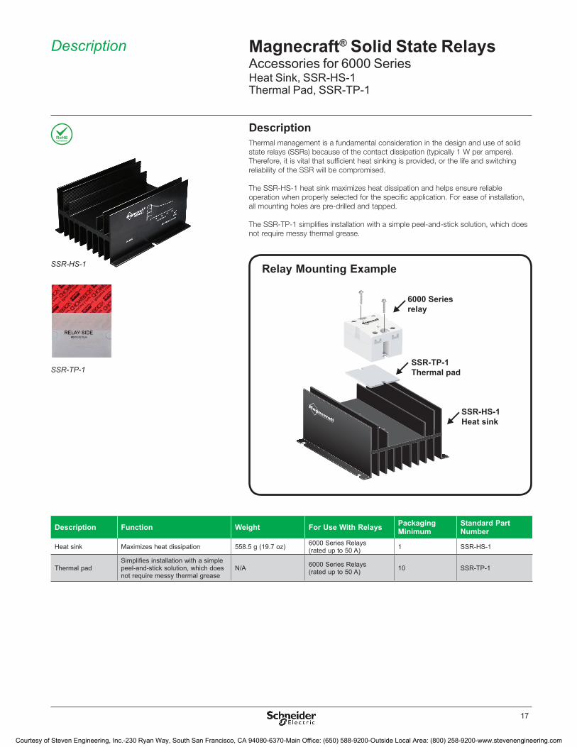
Relay Mounting Example
DescriptionThermal management is a fundamental consideration in the design and use of solid state relays (SSRs) because of the contact dissipation (typically 1 W per ampere). Therefore, it is vital that sufficient heat sinking is provided, or the life and switching reliability of the SSR will be compromised.
The SSR-HS-1 heat sink maximizes heat dissipation and helps ensure reliable operation when properly selected for the specific application. For ease of installation, all mounting holes are pre-drilled and tapped.
The SSR-TP-1 simplifies installation with a simple peel-and-stick solution, which does not require messy thermal grease.
Description Function Weight For Use With Relays Packaging Minimum
Standard Part Number
Heat sink Maximizes heat dissipation 558�5 g (19�7 oz) 6000 Series Relays (rated up to 50 A) 1 SSR-HS-1
Thermal padSimplifies installation with a simple peel-and-stick solution, which does not require messy thermal grease
N/A 6000 Series Relays (rated up to 50 A) 10 SSR-TP-1
6000 Seriesrelay
SSR-TP-1Thermal pad
SSR-HS-1Heat sink
SSR-HS-1
SSR-TP-1
Description Magnecraft® Solid State RelaysAccessories for 6000 SeriesHeat Sink, SSR-HS-1Thermal Pad, SSR-TP-1
Courtesy of Steven Engineering, Inc.-230 Ryan Way, South San Francisco, CA 94080-6370-Main Office: (650) 588-9200-Outside Local Area: (800) 258-9200-www.stevenengineering.com
18
De-Rating Curves (when used with thermal pad and heat sink)
0
10
100
20
30
40
60
AMBIENT TEMPERATURE (ºC)50 6030 70402010 80 90
50
0
10
100
20
30
40
60
AMBIENT TEMPERATURE (ºC)50 6030 70402010 80 90
50
200 6040 80
0.2
100 120 140
0.4
0.6
0.8
1.00.92
0.69
0.55 0.520.51
DISSIPATION (W)
THER
MA
L R
ESIS
TAN
CE
(ºC/W
)
50A 6000 Series Relay without Fan
Thermal Resistance vs Power Dissipation
CU
RR
ENT
RAT
ING
(A)
CU
RR
ENT
RAT
ING
(A)
37
28
47
38
24
19 14
Load Current vs Ambient Temperature (100% Duty Cycle)
50A 6000 Series Relay with (70 Cfm) Fan
2.22(56.3)
1.72(43.63)
0.88(22.45)
0.29(7.35)
INSTALLATION:1. RELEASE LINER ON ONE
SIDE OF THE THERMAL PAD,PLACE UNDERNEATH CLASS 6 SOLID STATE RELAY.
2. RELEASE LINER ON OTHER SIDE OF THERMAL PAD AND PLACE RELAY AND PAD ONTO HEAT SINK OR PANEL.
SSR-TP-1
TOP VIEW
FRONT VIEW
4.73(120.14)
1.75(44.45)
0.13(3.18)
0.19(4.95)
3.86(97.92)
0.34(8.69)
1.99(50.63)
0.07(1.69)
2.65(67.31)
5.51(139.95)
SIDE VIEW
0.24(6.04)
SSR-HS-1
Dimensions, De-Rating Curves
Magnecraft® Solid State RelaysAccessories for 6000 SeriesHeat Sink, SSR-HS-1Thermal Pad, SSR-TP-1
Dimensions: Inches (Millimeters)
Courtesy of Steven Engineering, Inc.-230 Ryan Way, South San Francisco, CA 94080-6370-Main Office: (650) 588-9200-Outside Local Area: (800) 258-9200-www.stevenengineering.com
19
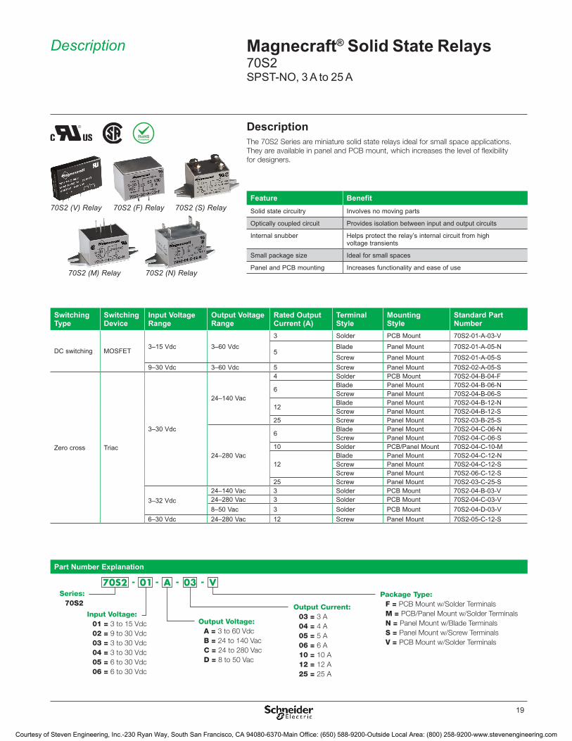
DescriptionThe 70S2 Series are miniature solid state relays ideal for small space applications. They are available in panel and PCB mount, which increases the level of flexibility for designers.
Switching Type
Switching Device
Input Voltage Range
Output Voltage Range
Rated Output Current (A)
Terminal Style
Mounting Style
Standard Part Number
DC switching MOSFET3–15 Vdc 3–60 Vdc
3 Solder PCB Mount 70S2-01-A-03-V
5Blade Panel Mount 70S2-01-A-05-NScrew Panel Mount 70S2-01-A-05-S
9–30 Vdc 3–60 Vdc 5 Screw Panel Mount 70S2-02-A-05-S
Zero cross Triac
3–30 Vdc
24–140 Vac
4 Solder PCB Mount 70S2-04-B-04-F
6Blade Panel Mount 70S2-04-B-06-NScrew Panel Mount 70S2-04-B-06-S
12Blade Panel Mount 70S2-04-B-12-NScrew Panel Mount 70S2-04-B-12-S
25 Screw Panel Mount 70S2-03-B-25-S
24–280 Vac
6Blade Panel Mount 70S2-04-C-06-NScrew Panel Mount 70S2-04-C-06-S
10 Solder PCB/Panel Mount 70S2-04-C-10-M
12Blade Panel Mount 70S2-04-C-12-NScrew Panel Mount 70S2-04-C-12-SScrew Panel Mount 70S2-06-C-12-S
25 Screw Panel Mount 70S2-03-C-25-S
3–32 Vdc24–140 Vac 3 Solder PCB Mount 70S2-04-B-03-V24–280 Vac 3 Solder PCB Mount 70S2-04-C-03-V8–50 Vac 3 Solder PCB Mount 70S2-04-D-03-V
6–30 Vdc 24–280 Vac 12 Screw Panel Mount 70S2-05-C-12-S
70S2 (V) Relay 70S2 (F) Relay
70S2 (M) Relay 70S2 (N) Relay
70S2 (S) Relay
Part Number Explanation
Series:70S2
Package Type:F = PCB Mount w/Solder TerminalsM = PCB/Panel Mount w/Solder TerminalsN = Panel Mount w/Blade TerminalsS = Panel Mount w/Screw TerminalsV = PCB Mount w/Solder Terminals
Output Voltage: A = 3 to 60 VdcB = 24 to 140 VacC = 24 to 280 VacD = 8 to 50 Vac
Output Current:03 = 3 A04 = 4 A05 = 5 A06 = 6 A10 = 10 A12 = 12 A25 = 25 A
Input Voltage:01 = 3 to 15 Vdc02 = 9 to 30 Vdc03 = 3 to 30 Vdc04 = 3 to 30 Vdc05 = 6 to 30 Vdc06 = 6 to 30 Vdc
Feature BenefitSolid state circuitry Involves no moving parts
Optically coupled circuit Provides isolation between input and output circuits
Internal snubber Helps protect the relay’s internal circuit from high voltage transients
Small package size Ideal for small spaces
Panel and PCB mounting Increases functionality and ease of use
Description Magnecraft® Solid State Relays70S2SPST-NO, 3 A to 25 A
Courtesy of Steven Engineering, Inc.-230 Ryan Way, South San Francisco, CA 94080-6370-Main Office: (650) 588-9200-Outside Local Area: (800) 258-9200-www.stevenengineering.com
20
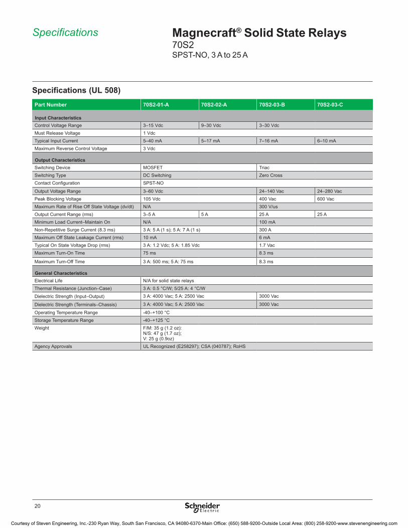
Specifications (UL 508)Part Number 70S2-01-A 70S2-02-A 70S2-03-B 70S2-03-C
Input Characteristics Control Voltage Range 3–15 Vdc 9–30 Vdc 3–30 VdcMust Release Voltage 1 VdcTypical Input Current 5–40 mA 5–17 mA 7–16 mA 6–10 mAMaximum Reverse Control Voltage 3 Vdc
Output Characteristics Switching Device MOSFET TriacSwitching Type DC Switching Zero CrossContact Configuration SPST-NO
Output Voltage Range 3–60 Vdc 24–140 Vac 24–280 VacPeak Blocking Voltage 105 Vdc 400 Vac 600 VacMaximum Rate of Rise Off State Voltage (dv/dt) N/A 300 V/usOutput Current Range (rms) 3–5 A 5 A 25 A 25 AMinimum Load Current–Maintain On N/A 100 mANon-Repetitive Surge Current (8�3 ms) 3 A: 5 A (1 s); 5 A: 7 A (1 s) 300 AMaximum Off State Leakage Current (rms) 10 mA 6 mATypical On State Voltage Drop (rms) 3 A: 1�2 Vdc; 5 A: 1�85 Vdc 1�7 VacMaximum Turn-On Time 75 ms 8�3 ms
Maximum Turn-Off Time 3 A: 500 ms; 5 A: 75 ms 8�3 ms
General Characteristics Electrical Life N/A for solid state relaysThermal Resistance (Junction–Case) 3 A: 0�5 °C/W; 5/25 A: 4 °C/W
Dielectric Strength (Input–Output) 3 A: 4000 Vac; 5 A: 2500 Vac 3000 Vac
Dielectric Strength (Terminals–Chassis) 3 A: 4000 Vac; 5 A: 2500 Vac 3000 Vac
Operating Temperature Range -40–+100 °CStorage Temperature Range -40–+125 °CWeight F/M: 35 g (1�2 oz):
N/S: 47 g (1�7 oz); V: 25 g (0�9oz)
Agency Approvals UL Recognized (E258297); CSA (040787); RoHS
Specifications Magnecraft® Solid State Relays70S2SPST-NO, 3 A to 25 A
Courtesy of Steven Engineering, Inc.-230 Ryan Way, South San Francisco, CA 94080-6370-Main Office: (650) 588-9200-Outside Local Area: (800) 258-9200-www.stevenengineering.com

21
Specifications (UL 508)Part Number 70S2-04-B 70S2-04-C 70S2-04-D 70S2-05-C 70S2-06-C
Input Characteristics Control Voltage Range 3 A: 3–32 Vdc; 4/6/10/12 A: 3–30 Vdc 6–30 Vdc 3–30 Vdc
Must Release Voltage 1 VdcTypical Input Current 3 A: 1–19 mA; 4/6/10/12 A: 7–16 mA 6–10 mA 1–17 mAMaximum Reverse Control Voltage 3 Vdc
Output Characteristics Switching Device TriacSwitching Type Zero CrossContact Configuration SPST-NO
Output Voltage Range 24–140 Vac 24–280 Vac 8–50 Vac 24–280 VacPeak Blocking Voltage 400 Vac 600 Vac 200 Vac 600 VacMaximum Rate of Rise Off State Voltage (dv/dt) 300 V/usOutput Current Range (rms) 3–12 A 3–12 A 3 A 12 AMinimum Load Current–Maintain On 3/4/6 A: 75 mA; 10/12 A: 100 mANon-Repetitive Surge Current (8�3 ms) 3/4/6 A: 60 A; 10/12 A: 150 AMaximum Off State Leakage Current (rms) 6 mA 10 mA 6 mATypical On State Voltage Drop (rms) 1�6 VacMaximum Turn-On Time 8�3 ms
Maximum Turn-Off Time 8�3 ms
General Characteristics Electrical Life N/A for solid state relaysThermal Resistance (Junction–Case) 3 A: 0�5 °C/W ; 4/6/10/12 A: 4 °C/W 2�4 °C/W
Dielectric Strength (Input–Output) 3 A: 4000 Vac; 4/6/10/12 A: 3000 Vac
Dielectric Strength (Terminals–Chassis) 3 A: 4000 Vac; 4/6/10/12 A: 3000 Vac
Operating Temperature Range -40–+100 °C (derating applies)Storage Temperature Range -40–+125 °CWeight F/M: 35 g (1�2 oz):
N/S: 47 g (1�7 oz); V: 25 g (0�9 oz);
Agency Approvals UL Recognized (E258297); CSA (040787); RoHS
Specifications (continued) Magnecraft® Solid State Relays70S2SPST-NO, 3 A to 25 A
Courtesy of Steven Engineering, Inc.-230 Ryan Way, South San Francisco, CA 94080-6370-Main Office: (650) 588-9200-Outside Local Area: (800) 258-9200-www.stevenengineering.com
22
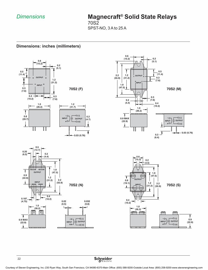
Dimensions: inches (millimeters)
1.7(43.2)
1.02(26.0)
0.9(22.9)
1.1(27.9)
0.2(5.1)
0.3(7.6)
0.4(10.2)
0.16(4.1)
0.4(10.2)
0.04 DIA.(1.0)
+
-
0.032(0.8)
0.02(0.5)
OUTPUT
INPUT
0.2(4.4)
1.2(31.2)
1.9(47.5)
2.2(55.9)
0.4(10.2)
1.0(26.2)
0.9 MAX(22.9)
0.5(12.7)
0.9(22.9)
0.187(4.75)
0.25(6.5)
0.2(5.1)
1.2(31.2)
0.4(10.2)
0.3(7.6)
0.6(15.2)
0.5(11.4)
0.3(7.6)
0.2(4.7)
1.0 (26.2)
0.8 (20.7)
1.2(31.7)
0.03 (0.76)
70S2 (F) 70S2 (M)
70S2 (N)
70S2 (V)
70S2 (S)
0.2(4.4)
1.2(31.2)
1.9(47.5)
2.2(55.9)
1.0(26.2)
0.9 MAX(22.9)
0.4(10.2)
0.6(15.2) 0.2
(5.1)
0.3(7.6)
0.5(11.4)
0.3(7.6)
0.3(6.4)
INPUT
OUTPUT
INPUT
OUTPUT
0.03 (0.76)
0.8(19.1)
0.9 (22.9)
+
-
+
-
+
-
0.4(10.2)
0.6(15.3) 0.2
(4.5)
2.2(55.9)
1.9(47.5)
1.2(31.2)
1.0(26.2)
OUTPUT
INPUT
OUTPUTINPUT– + – +
(-)
(+)
(-)
(+)
(-)
(+)
(-)
(+)INPUT INPUT
INPUTINPUT
OUTPUT OUTPUT
OUTPUTOUTPUT
Magnecraft® Solid State Relays70S2SPST-NO, 3 A to 25 A
Dimensions
Courtesy of Steven Engineering, Inc.-230 Ryan Way, South San Francisco, CA 94080-6370-Main Office: (650) 588-9200-Outside Local Area: (800) 258-9200-www.stevenengineering.com
23
Wiring Diagram
INPUT
+
INP
UT
OU
TP
UT
OUTPUTPOWER SOURCE
POWER SUPPLY
SSR
-
LOAD
(-)(-)
(+)(+)
MOSFET ONLY
De-Rating Curves
1.7(43.2)
1.02(26.0)
0.9(22.9)
1.1(27.9)
0.2(5.1)
0.3(7.6)
0.4(10.2)
0.16(4.1)
0.4(10.2)
0.04 DIA.(1.0)
+
-
0.032(0.8)
0.02(0.5)
OUTPUT
INPUT
0.2(4.4)
1.2(31.2)
1.9(47.5)
2.2(55.9)
0.4(10.2)
1.0(26.2)
0.9 MAX(22.9)
0.5(12.7)
0.9(22.9)
0.187(4.75)
0.25(6.5)
0.2(5.1)
1.2(31.2)
0.4(10.2)
0.3(7.6)
0.6(15.2)
0.5(11.4)
0.3(7.6)
0.2(4.7)
1.0 (26.2)
0.8 (20.7)
1.2(31.7)
0.03 (0.76)
70S2 (F) 70S2 (M)
70S2 (N)
70S2 (V)
70S2 (S)
0.2(4.4)
1.2(31.2)
1.9(47.5)
2.2(55.9)
1.0(26.2)
0.9 MAX(22.9)
0.4(10.2)
0.6(15.2) 0.2
(5.1)
0.3(7.6)
0.5(11.4)
0.3(7.6)
0.3(6.4)
INPUT
OUTPUT
INPUT
OUTPUT
0.03 (0.76)
0.8(19.1)
0.9 (22.9)
+
-
+
-
+
-
0.4(10.2)
0.6(15.3) 0.2
(4.5)
2.2(55.9)
1.9(47.5)
1.2(31.2)
1.0(26.2)
OUTPUT
INPUT
OUTPUTINPUT– + – +
(-)
(+)
(-)
(+)
(-)
(+)
(-)
(+)INPUT INPUT
INPUTINPUT
OUTPUT OUTPUT
OUTPUTOUTPUT
Dimensions: inches (millimeters)
Load Current vs Ambient Temperature (100% Duty Cycle)
16
12
20
24
28
32
8
4
100
10
25
30
30 50 7020 40 60 80
LOA
D C
UR
REN
T IN
AM
PER
ES
MAX. AMBIENT TEMPERATURE IN °C
10, 12 & 25 A
4
3
5
6
7
8
2
1
100 30 50 7020 40 60 80
4 & 6 A
LOA
D C
UR
REN
T IN
AM
PER
ES
MAX. AMBIENT TEMPERATURE IN °C
4
3
5
6
7
8
2
1
100 30 50 7020 40 60 80
3 & 5 A
LOA
D C
UR
REN
T IN
AM
PER
ES
MAX. AMBIENT TEMPERATURE IN °C
Magnecraft® Solid State Relays70S2SPST-NO, 3 A to 25 A
Dimensions (continued), Wiring Diagram, De-Rating Curves
Courtesy of Steven Engineering, Inc.-230 Ryan Way, South San Francisco, CA 94080-6370-Main Office: (650) 588-9200-Outside Local Area: (800) 258-9200-www.stevenengineering.com

24
EMR vs SSR Technology
ARMATURE
MECHANICALCONTACTS
COIL
MAGNETICCOUPLING
EMR
OPTICALCOUPLING
CURRENTLIMITER
LED
PHOTODETECTOR
SNUBBER
TRIGGER
OUTPUTDEVICE(SSR)
SSR
Application Data Magnecraft® Solid State Relays
DefinitionA solid state relay (SSR) can perform many tasks that an electromechanical relay (EMR) can perform� The SSR differs in that it has no moving mechanical parts� It is essentially an electronic device that relies on the electrical and optical properties of semiconductors to achieve its isolation and switching function�
Principle of OperationSSRs are similar to electromechanical relays, in that both use a control circuit and a separate circuit for switching the load� When voltage is applied to the input of the SSR, the relay is energized by a light emitting diode� The light from the diode is beamed into a light sensitive semiconductor which conditions the control circuit to turn on the output solid state switch� In the case of zero voltage crossover relays, the output solid state switch is turned on at the zero crossing of AC voltage� Removal of the input power disables the control circuit and the solid state switch also turns off when the load current passes through the zero point of its cycle� Zero cross is only applied to AC switching circuits� DC switching circuits operate at an instant on/off rate�
AdvantagesWhen used correctly in the intended application, the SSR provides many of the characteristics that are often difficult to find in the EMR: a high degree of reliability, long service life, significantly reduced electromagnetic interference, fast response and high vibration resistance are significant benefits of the SSR� The SSR has no moving parts to wear out or arcing contacts to deteriorate, which are often the primary cause of failure with an EMR�
Long life (reliability) > 1E+9 operations �
Zero voltage turn on, low EMI/RFI �
Shock and vibration resistant �
Random turn-on, proportional control �
No contact bounce �
Arc-less switching �
No acoustical noise �
TTL compatible �
Fast response �
No moving parts �
Courtesy of Steven Engineering, Inc.-230 Ryan Way, South San Francisco, CA 94080-6370-Main Office: (650) 588-9200-Outside Local Area: (800) 258-9200-www.stevenengineering.com

25
ApplicationsSince its introduction, SSR technology has gained acceptance in many applications that had previously been the sole domain of the EMR or contactor� The major growth areas have come from industrial process control applications; particularly heat/cool temperature control, motors, lamps, solenoids, valves, and transformers� The list of applications for the SSR is almost limitless�
Oil & GasBurner assemblies, chemical injection systems, extraction machines, re�ning machines, solenoid control
Electronic AppliancesDomestic appliances, cooking appliances, heating elements, audio equipment
Idustrial AutomationAutomotive assembly plants, conveyance, motor control
Industrial AppliancesIndustrial cleaning equipment, commercial coffee machines, commercial/industrial cooking equipment
PackagingConveyor motors, heaters, product/shrink wrap, solenoid control
High ReliabilityMedical equipment, lifts & escalators, low switching noise, low electromagnetic interference, automatic door operation
HVAC & RefridgerationAnti-condensation equipment, compressor control, blower control, motorized duct/vent control
Lighting ControlTraf�c signal systems, motorway information systems, theatrical lighting
Food & BeverageCommercial/industrial cooking equipment, �ltration systems, bottleing, chillers, convection ovens
Industrial Heater ControlPlastics industry: drying, extrusion/thermoforming, heat tracing, solder wave/re�ow systems, car wash pumps and dryers
MiningBlower control, motorized duct/vent control, drill control, explosive control, mineral extractors
Typical Examples of SSR Applications
Application Data (continued) Magnecraft® Solid State Relays
Courtesy of Steven Engineering, Inc.-230 Ryan Way, South San Francisco, CA 94080-6370-Main Office: (650) 588-9200-Outside Local Area: (800) 258-9200-www.stevenengineering.com
26
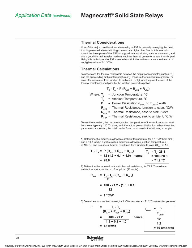
Thermal ConsiderationsOne of the major considerations when using a SSR is properly managing the heat that is generated when switching currents are higher than 5 A� In this scenario mount the base plate of the SSR on a good heat conductor, such as aluminum, and use a good thermal transfer medium, such as thermal grease or a heat transfer pad� Using this technique, the SSR case to heat sink thermal resistance is reduced to a negligible value of 0.1 ˚C/W.
Thermal CalculationsTo understand the thermal relationship between the output semiconductor junction (TJ) and the surrounding ambient temperature (TA) measure the temperature gradient, or drop of temperature, from junction to ambient (TJ - TA); which equals the sum of the thermal resistances multiplied by the junction power dissipation�
TJ - TA = P (RөJC + RөCS + RөSA)
Where: TJ = Junction Temperature, °C TA = Ambient Temperature, °C P = Power Dissipation (ILOAD 3 EDROP) watts RөJC = Thermal Resistance, junction to case, °C/W RөCS = Thermal Resistance, case to sink, °C/W RөSA = Thermal Resistance, sink to ambient, °C/W
To use the equation, the maximum junction temperature of the semiconductor must be known, typically 125 ˚C, along with the actual power dissipation. When these two parameters are known, the third can be found as shown in the following example:
Application Data (continued) Magnecraft® Solid State Relays
1) Determine the maximum allowable ambient temperature, for a 1 ̊ C/W heat sink and a 10 A load (12 watts) with a maximum allowable junction temperature (TJ) of 100 ˚C, and assume a thermal resistance from junction to case (RөJC) of 1�3:
TJ - TA = P (RөJC + RөCS + RөSA) = 12 (1.3 + 0.1 + 1.0) hence: = 28.8
2) Determine the required heat sink thermal resistance, for 71.2 ˚C maximum ambient temperature and a 10 amp load (12 watts):
RөSA = TJ - TA - (RөJC + RөCS) P
= 100 - 71.2 - (1.3 + 0.1) 12
= 1 °C/W
3) Determine maximum load current, for 1 ˚C/W heat sink and 71.2 ˚C ambient temperature:
P = TJ - TA
(RөJC + RөCS + RөSA)
= 100 - 71.2 hence: 1.3 + 0.1 + 1.0 = 12 watts
TA = TJ–28.8 = 100–28.8 = 71.2 °C
ILOAD = P EDROP
12 1.2 = 10 amperes
Courtesy of Steven Engineering, Inc.-230 Ryan Way, South San Francisco, CA 94080-6370-Main Office: (650) 588-9200-Outside Local Area: (800) 258-9200-www.stevenengineering.com
27
Application Data (continued) Magnecraft® Solid State Relays
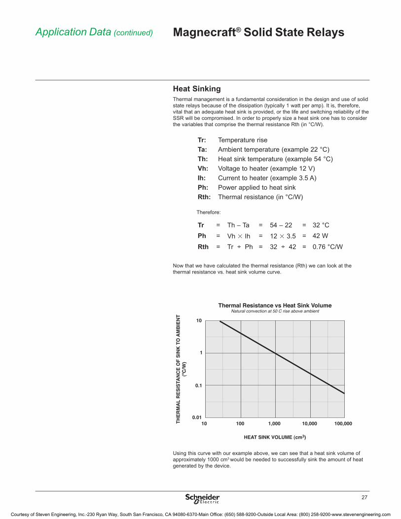
Heat SinkingThermal management is a fundamental consideration in the design and use of solid state relays because of the dissipation (typically 1 watt per amp)� It is, therefore, vital that an adequate heat sink is provided, or the life and switching reliability of the SSR will be compromised� In order to properly size a heat sink one has to consider the variables that comprise the thermal resistance Rth (in °C/W)�
Tr: Temperature riseTa: Ambient temperature (example 22 °C)Th: Heat sink temperature (example 54 °C)Vh: Voltage to heater (example 12 V)Ih: Current to heater (example 3�5 A)Ph: Power applied to heat sinkRth: Thermal resistance (in °C/W)
Therefore:
Tr = Th – Ta = 54 – 22 = 32 °CPh = Vh 3 Ih = 12 3 3�5 = 42 W
Rth = Tr ÷ Ph = 32 ÷ 42 = 0�76 °C/W
Now that we have calculated the thermal resistance (Rth) we can look at the thermal resistance vs� heat sink volume curve�
Using this curve with our example above, we can see that a heat sink volume of approximately 1000 cm3 would be needed to successfully sink the amount of heat generated by the device�
Thermal Resistance vs Heat Sink VolumeNatural convection at 50 C rise above ambient
10
1
0.1
0.01
THER
MA
L R
ESIS
TAN
CE
OF
SIN
K T
O A
MB
IEN
T(ºC
/W)
10 100 1,000 10,000 100,000
HEAT SINK VOLUME (cm3)
Courtesy of Steven Engineering, Inc.-230 Ryan Way, South San Francisco, CA 94080-6370-Main Office: (650) 588-9200-Outside Local Area: (800) 258-9200-www.stevenengineering.com
28
Load ConsiderationsThe major cause of application problems with SSRs is improper heat sinking� Following that are issues which result from operating conditions which specific loads impose upon an SSR� Carefully considered the surge characteristics of the load when designing an SSR as a switching solution�
• Resistive LoadsLoads of constant value of resistance are the simplest application of SSRs� Proper thermal consideration along with attention to the steady state current ratings is important for reliable operation�
• DC LoadsDC loads are inductive loads� Place a diode across the load to absorb surges during turn off�
• Lamp LoadsIncandescent lamp loads, though basically resistive, require special consideration� Because the resistance of the cold filament is about 5 to 10 percent of the heated value, a large inrush current can occur� It is essential to verify that this inrush current is within the surge specifications of the SSR� One must also check that the lamp rating of the SSR is not exceeded� This is a UL rating based on the inrush of a typical lamp� Due to the unusually low filament resistance at the time of turn-on, a zero voltage turn on characteristic is particularly desirable with incandescent lamps�
• Capacitive LoadsThese types of loads can be difficult because of their initial appearance as short circuits� High surge currents can occur while charging, limited only by circuit resistance� Use caution with low impedance capacitive loads to verify that the dl/dt capabilities are not exceeded� Zero voltage turn on is a particularly valuable means of limiting dl/dt with capacitive loads�
• Motors and SolenoidsMotor and solenoid loads require special attention for reliable SSR functionality� Solenoids have high initial surge currents because their stationary impedance is very low� Motors also frequently have severe inrush currents during starting and can impose unusually high voltages during turn off� As a motor’s rotor rotates, it creates a back EMF that reduces the flow of current� This back EMF can add to the applied line voltage and create an over voltage condition during turn off� Likewise, verify that the inrush currents associated with mechanical loads having high starting torque or inertia, such as fans and flywheels, are within the surge capabilities of the SSR� Use a current shunt and oscilloscope to examine the duration of the inrush current�
Application Data (continued) Magnecraft® Solid State Relays
Courtesy of Steven Engineering, Inc.-230 Ryan Way, South San Francisco, CA 94080-6370-Main Office: (650) 588-9200-Outside Local Area: (800) 258-9200-www.stevenengineering.com
29
TransformersIn controlling transformers, consider the characteristics of the secondary load because they reflect the effective load on the SSR� Voltage transients from secondary loads circuits, similarly, are frequently transformers and can be imposed on the SSR� Transformers present a special challenge in that, depending on the state of the transformer flux at the time of turn off, the transformer may saturate during the first half-cycle of subsequently applied voltage� This saturation can impose a very large current (10 to 100 times rated typical) on the SSR which far exceeds its half cycle surge rating� SSRs having random turn on may have a better chance of survival than a zero cross turn on device for they commonly require the transformer to support only a portion of the first half cycle of the voltage� On the other hand, a random turn on device will frequently close at the zero cross point and then the SSR must sustain the worst case saturation current� A zero cross turn on device has the advantage that it turns on in a known mode and will immediately demonstrate the worst case condition� The use of a current shunt and an oscilloscope is recommended to verify that the half cycle surge capability is not exceeded�
A rule of thumb in applying an SSR to a transformer load is to select an SSR having a half cycle current surge rating greater than the maximum applied line voltage divided by the transformer primary resistance� The primary resistance is usually easily measured and can be relied on as a minimum impedance limiting the first half cycle of inrush current� The presence of some residual flux plus the saturated reactance of the primary will then further limit, in the worst case, the half cycle surge safely within the surge rating of the SSR�
Switching DevicesThe power family of semiconductors consists of several switching devices� The most widely used of this family are metal-oxide semiconductor field effect transistors (MOSFETs), silicon controlled rectifiers (SCRs), Triac, and Alternistor Triac� In many applications these devices perform key functions and therefore it is imperative that one understand their advantages as well as their shortcomings to properly design a reliable system� Once applied correctly SSRs are an asset in meeting environmental, speed, and reliability specifications which their electromechanical counterparts could not fulfill�
• MOSFETA power MOSFET is a specific type of metal oxide semiconductor field-effect transistor (MOSFET) designed to handle large amounts of power� It is a vertical structured transistor capable of sustaining high blocking voltage and high current� Power MOSFET’s are used in DC switching applications� Care must be taken to ensure that there is proper polarity for all DC ports� Failure to do so can lead to permanent device damage�
• TriacA TRIAC, is an electronic component approximately equivalent to two silicon-controlled rectifiers joined in inverse parallel (paralleled but with the polarity reversed) and with their gates connected together� This results in a bidirectional electronic switch which can conduct AC current only� The Triac is ideal for switching non-reactive loads�
• Alternistor TriacThe Alternistor has been specifically designed for applications that switch highly inductive AC loads� A special chip offers similar performance as two SCRs wired inverse parallel (back-to-back), providing better turn-off behavior than a standard Triac� The Alternistor Triac is an economical solution; ideal for switching inductive AC loads�
• SCRThe SCR (silicon-controlled rectifier) acts as a switch, conducting when its gate receives a current pulse, and continue to conduct for as long as it is forward biased� The SCR is ideal for switching all types of AC loads�
Application Data (continued) Magnecraft® Solid State Relays
Courtesy of Steven Engineering, Inc.-230 Ryan Way, South San Francisco, CA 94080-6370-Main Office: (650) 588-9200-Outside Local Area: (800) 258-9200-www.stevenengineering.com
30
The Magnecraft Range of Solid State RelaysDepending on the application, the Magnecraft line of solid state relays offers a number of advantages over electromechanical relays, including longer life cycles, less energy consumption and reduced maintenance costs�
Selecting a Solid State RelayThe list below is an example of the specifications to look for when selecting a solid state relay�
Use the catalog specifications or online parametric search to determine a recommended part number (www.magnecraft.com)�
Selection Guide Magnecraft® Solid State Relays
Class 1, Division 2 certification (y/n):
Input voltage:
Output voltage:
Load rating:
Contact configuration:
Ambient temperature:
In-rush currents:
Mounting style:
__________________
__________________
__________________
__________________
__________________
__________________
__________________
__________________
More About Class 1, Division 2 Certified ProductsClass 1, Division 2 is a classification which was developed by American National Standards Institute (ANSI) to provide requirements for the design and construction of electrical equipment and parts that will be used in hazardous locations� Certified components, when used properly, are not capable of igniting the surrounding atmosphere�
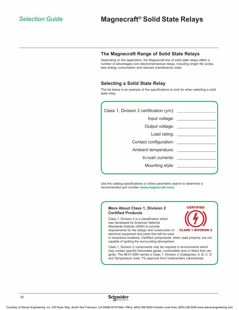
Class 1, Division 2 components may be required in environments which may contain specific flammable gases, combustible dust or fibers that can ignite� The 861H SSR carries a Class 1, Division 2 (Categories: A, B, C, D and Temperature code: T5) approval from Underwriters Laboratories�
Courtesy of Steven Engineering, Inc.-230 Ryan Way, South San Francisco, CA 94080-6370-Main Office: (650) 588-9200-Outside Local Area: (800) 258-9200-www.stevenengineering.com
31
Website Guide Magnecraft® Solid State Relays
The Magnecraft website (www.magnecraft.com) was designed to enable users to easily find the proper relay to fit design requirements and to help simplify and shorten workflow�
Easily find the proper relay to fit design requirements
� Online CatalogFind the right product by choosing specifications, compare products side-by-side, and view technical specifications, 2D and 3D drawings, and associated accessories�
� Cross Reference SearchSearch our comprehensive database to identify products by manufacturer and part number, and link directly to part specifications�
� 3D CAD LibraryView, email, download or insert a file directly into your open CAD software pane and select from 18 different file formats�
� Order Free SamplesMagnecraft offers free samples as a courtesy to individuals and companies evaluating our products in their designs and applications� Sample orders are subject to approval�
Simplify and shorten workflow
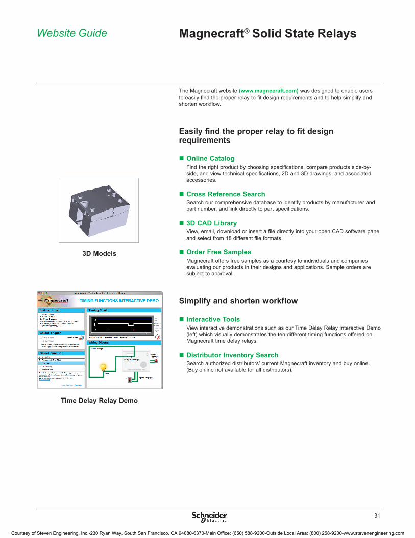
� Interactive ToolsView interactive demonstrations such as our Time Delay Relay Interactive Demo (left) which visually demonstrates the ten different timing functions offered on Magnecraft time delay relays�
� Distributor Inventory SearchSearch authorized distributors’ current Magnecraft inventory and buy online� (Buy online not available for all distributors)�
Time Delay Relay Demo
3D Models
Courtesy of Steven Engineering, Inc.-230 Ryan Way, South San Francisco, CA 94080-6370-Main Office: (650) 588-9200-Outside Local Area: (800) 258-9200-www.stevenengineering.com

The information and dimensions in this catalog are provided for the convenience of our customers� While this information is believed to be accurate, Schneider Electric reserves the right to make updates and changes without prior notification and assumes no liability for any errors or omissions.
Design: Schneider ElectricPhotos: Schneider Electric
© 2010 Schneider Electric� All Rights Reserved� October 2010
8501
CT1
002Schneider Electric USA, Inc. www�magnecraft�com
1300 S� Wolf Rd�Des Plaines, IL 60018Tel: 847-441-2540
Courtesy of Steven Engineering, Inc.-230 Ryan Way, South San Francisco, CA 94080-6370-Main Office: (650) 588-9200-Outside Local Area: (800) 258-9200-www.stevenengineering.com


