
S E R I E SSEISMIC ENGINEERING RESEARCH INFRASTRUCTURES FOR EUROPEAN SYNERGIES
COMMISSION OF THE EUROPEAN COMMUNITIESFP7- INFRASTRUCTURES-2008-1SP4-Capacities
SERIES LNEC Training Course, Lisbon, 23 September 2012
Physical Modelling,
Instrumentation and Testing
Paulo Xavier CandeiasPost-PhD Grant Holder LNEC

SEISMIC ENGINEERING RESEARCH INFRASTRUCTURES FOR EUROPEAN SYNERGIES
SERIES LNEC Training Course, Lisbon, 23 September 2012
Presentation outline
• Physical modelling
▫ Prototypes and models
▫ Similitude laws
• Instrumentation plan
▫ What to measure?
▫ Where to measure?
• Testing protocol
▫ Dynamic tests
▫ Seismic tests
• Shaking table operation

SEISMIC ENGINEERING RESEARCH INFRASTRUCTURES FOR EUROPEAN SYNERGIES
SERIES LNEC Training Course, Lisbon, 23 September 2012
Physical modelling
• Seismic behaviour of real structures is complex;
• In order to study it on a controlled environment, prototypes of real structures have to be selected;
• Prototypes should include all the relevant elements that influence the seismic behaviour:
▫ Main structural elements (columns, beams, slabs, walls);
▫ Influencing nonstructural elements (e.g., partition walls, heavy equipments).

SEISMIC ENGINEERING RESEARCH INFRASTRUCTURES FOR EUROPEAN SYNERGIES
SERIES LNEC Training Course, Lisbon, 23 September 2012
Physical modelling
• Construction of physical models in natural scale is frequently not possible due to several types of constraints :
▫ Geometrical
▫ Physical
• The construction of physical models can pose serious challenges:
▫ Materials
▫ Methods

SEISMIC ENGINEERING RESEARCH INFRASTRUCTURES FOR EUROPEAN SYNERGIES
SERIES LNEC Training Course, Lisbon, 23 September 2012
Example
• Consider a reinforced concrete model built in a 1:1.5 reduced scale
Issue Prototype Model
Concrete maximumaggregate diameter
2.4cm 1.6cm
Concrete cover 2cm 1.33cm
8mm steel rebar 8mm 5.33mm
16mm steel rebar 16mm 10.67mm
22×11×7 bricks 22×11×7 14.67×7.33×4.67
30×20×15 bricks 30×20×15 20×13.33×10

SEISMIC ENGINEERING RESEARCH INFRASTRUCTURES FOR EUROPEAN SYNERGIES
SERIES LNEC Training Course, Lisbon, 23 September 2012
Dimensional analysis
• Buckingham Pi Theorem:
▫ Any dimensionally homogeneous equation involving certain physical quantities can be reduced to an equivalent equation involving a complete set of dimensionless products.
• This theorem states that the solution equation for some physical quantity of interest, i.e.,
can equivalently be expressed in the form
( ) 0,,, 21 =nXXXF K
( ) 0,,, 21 =ΠΠΠ mG K

SEISMIC ENGINEERING RESEARCH INFRASTRUCTURES FOR EUROPEAN SYNERGIES
SERIES LNEC Training Course, Lisbon, 23 September 2012
Dimensional analysis
• The Pi terms are dimensionless products of the physical quantities X1, X2, ..., Xn.
• A complete set of dimensionless products are the m=n-r independent products that can be formed from the physical quantities X1, X2, ..., Xn.
• Generally, it can be stated that the number of dimensionless products (m) is equal to the difference between the number of physical variables (n) and the number of physical measures (r) that are involved.

SEISMIC ENGINEERING RESEARCH INFRASTRUCTURES FOR EUROPEAN SYNERGIES
SERIES LNEC Training Course, Lisbon, 23 September 2012
Physical quantities of interest in
seismic tests
Quantity Dimension Quantity Dimension
Length, L L Mass, m ρL3
Mass density, ρ ρ Force, F F
Young’s modulus, E FL-2 Weight, W F
Area, A L2 Moment, M FL
Volume, V L3 Stress, σ E or FL-2
Time, t T Strain, ε -
Frequency, f T-1 Poisson’s ratio, ν -
Displacement, d L Pressure, q FL-2
Velocity, v LT-1 Energy FL
Acceleration, a LT-2 Gravitational acceleration, g
LT-2
SEISMIC ENGINEERING RESEARCH INFRASTRUCTURES FOR EUROPEAN SYNERGIES
SERIES LNEC Training Course, Lisbon, 23 September 2012
Dimensional analysis
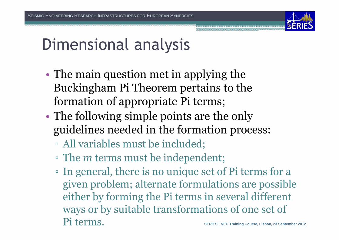
• The main question met in applying the Buckingham Pi Theorem pertains to the formation of appropriate Pi terms;
• The following simple points are the only guidelines needed in the formation process:
▫ All variables must be included;
▫ The m terms must be independent;
▫ In general, there is no unique set of Pi terms for a given problem; alternate formulations are possible either by forming the Pi terms in several different ways or by suitable transformations of one set of Pi terms.

SEISMIC ENGINEERING RESEARCH INFRASTRUCTURES FOR EUROPEAN SYNERGIES
SERIES LNEC Training Course, Lisbon, 23 September 2012
• Cauchy number:
• Froude number:
Dimensionless relations of interest
in seismic tests
ForceGravity
Force Inertial2
⇒=gl
vFr
Force Restoring Elastic
Force Inertial2
⇒=E
vCa
ρ
SEISMIC ENGINEERING RESEARCH INFRASTRUCTURES FOR EUROPEAN SYNERGIES
SERIES LNEC Training Course, Lisbon, 23 September 2012
Models used in seismic tests
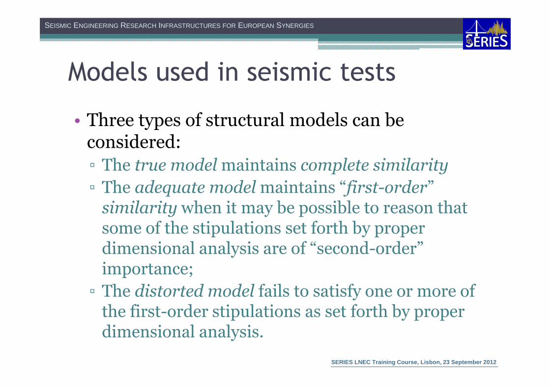
• Three types of structural models can be considered:
▫ The true model maintains complete similarity
▫ The adequate model maintains “first-order” similarity when it may be possible to reason that some of the stipulations set forth by proper dimensional analysis are of “second-order” importance;
▫ The distorted model fails to satisfy one or more of the first-order stipulations as set forth by proper dimensional analysis.

SEISMIC ENGINEERING RESEARCH INFRASTRUCTURES FOR EUROPEAN SYNERGIES
SERIES LNEC Training Course, Lisbon, 23 September 2012
Models used in seismic tests
• True replica models: Cauchy-Froude similitude
▫ Duplication of inertial, gravitational and restoring forces
▫ Such models are practically impossible to build and test because of the severe restrictions imposed on the model material properties, especially the mass density

SEISMIC ENGINEERING RESEARCH INFRASTRUCTURES FOR EUROPEAN SYNERGIES
SERIES LNEC Training Course, Lisbon, 23 September 2012
Models used in seismic tests
• Artificial mass simulation: Cauchy-Froude similitude
▫ Additional material of a nonstructural nature is added to simulate the required density of the model
• Gravity forces neglected: Cauchy-only similitude
▫ Applies in the case where gravity stresses can be neglected and where the same materials are used in both the model and the prototype to enable the testing to proceed to failure

SEISMIC ENGINEERING RESEARCH INFRASTRUCTURES FOR EUROPEAN SYNERGIES
SERIES LNEC Training Course, Lisbon, 23 September 2012
Cauchy-Froude scaling factors
Quantity Scale factor Quantity Scale factor
Length, L Lp/Lm=λ Mass, m eλ2
Mass density, ρ ρp/ρm=e/λ Weight, w eλ2
Young’s modulus, E Ep/Em=e Force, F eλ2
Area, A λ2 Moment, M λ3
Volume, V λ3 Stress, σ e
Time, t λ1/2 Strain, ε 1
Frequency, f λ-1/2 Poisson’s ratio, ν 1
Displacement, d λ Pressure, q e
Velocity, v λ1/2 Energy λ3
Acceleration, a 1 Gravitational acceleration, g
1

SEISMIC ENGINEERING RESEARCH INFRASTRUCTURES FOR EUROPEAN SYNERGIES
SERIES LNEC Training Course, Lisbon, 23 September 2012
Cauchy-only scaling factors
Quantity Scale factor Quantity Scale factor
Length, L Lp/Lm=λ Mass, m λ3
Mass density, ρ ρp/ρm=1 Weight, w λ3
Young’s modulus, E Ep/Em=1 Force, F λ2
Area, A λ2 Moment, M λ3
Volume, V λ3 Stress, σ 1
Time, t λ Strain, ε 1
Frequency, f λ-1 Poisson’s ratio, ν 1
Displacement, d λ Pressure, q 1
Velocity, v 1 Energy λ3
Acceleration, a λ-1 Gravitational acceleration, g
Neglected
SEISMIC ENGINEERING RESEARCH INFRASTRUCTURES FOR EUROPEAN SYNERGIES
SERIES LNEC Training Course, Lisbon, 23 September 2012
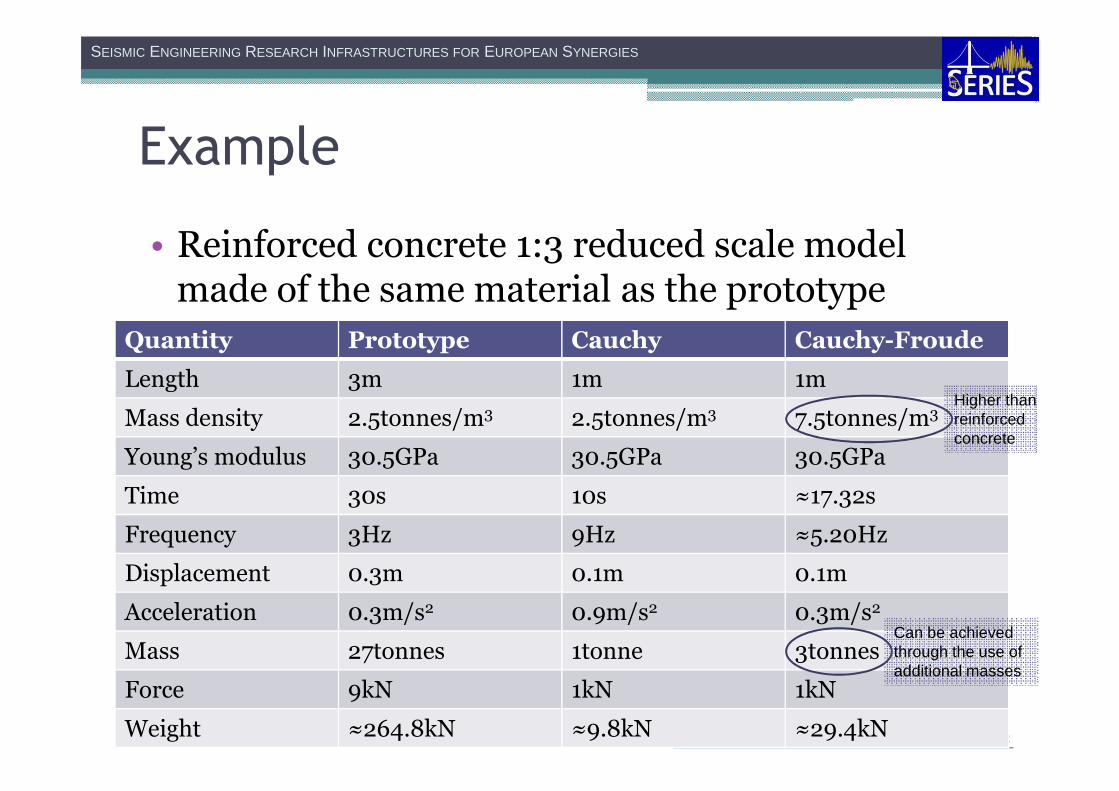
Example
• Reinforced concrete 1:3 reduced scale model made of the same material as the prototype
Quantity Prototype Cauchy Cauchy-Froude
Length 3m 1m 1m
Mass density 2.5tonnes/m3 2.5tonnes/m3 7.5tonnes/m3
Young’s modulus 30.5GPa 30.5GPa 30.5GPa
Time 30s 10s ≈17.32s
Frequency 3Hz 9Hz ≈5.20Hz
Displacement 0.3m 0.1m 0.1m
Acceleration 0.3m/s2 0.9m/s2 0.3m/s2
Mass 27tonnes 1tonne 3tonnes
Force 9kN 1kN 1kN
Weight ≈264.8kN ≈9.8kN ≈29.4kN
Can be achieved through the use of additional masses
Higher than reinforced concrete

SEISMIC ENGINEERING RESEARCH INFRASTRUCTURES FOR EUROPEAN SYNERGIES
SERIES LNEC Training Course, Lisbon, 23 September 2012
Instrumentation plan
• Measure the response of the physical model:
▫ Dynamic characteristics
▫ Seismic behaviour
• Adequate selection of measurement points;
• Must be adjusted to the dynamic/seismic behaviour of the physical model:
▫ Reinforced concrete
▫ Masonry (brick/block/stone)
▫ Steel

SEISMIC ENGINEERING RESEARCH INFRASTRUCTURES FOR EUROPEAN SYNERGIES
SERIES LNEC Training Course, Lisbon, 23 September 2012
Instrumentation plan
• Typical selection of measurements and measurement points in reinforced concrete structures (assuming rigid diaphragms):
▫ Three uniaxial accelerometers per floor
▫ Absolute floor displacements measured with optical transducers
▫ Relative displacements between floors measured with LVDT’s

SEISMIC ENGINEERING RESEARCH INFRASTRUCTURES FOR EUROPEAN SYNERGIES
SERIES LNEC Training Course, Lisbon, 23 September 2012
Instrumentation plan
• Typical selection of measurements and measurement points in masonry structures (assuming flexible diaphragms):
▫ Uniaxial accelerometers on the walls at the floor levels and at mid height
▫ Absolute wall displacements measured with optical transducers
▫ Relative displacements between floors measured with LVDT’s

SEISMIC ENGINEERING RESEARCH INFRASTRUCTURES FOR EUROPEAN SYNERGIES
SERIES LNEC Training Course, Lisbon, 23 September 2012
Example
• Instrumentation plan of the hands-on application
Sensors Quantity
Accelerometers 16
Optical displacementtransducers
4

SEISMIC ENGINEERING RESEARCH INFRASTRUCTURES FOR EUROPEAN SYNERGIES
SERIES LNEC Training Course, Lisbon, 23 September 2012
Testing protocol
• The testing protocol depends on the objectives of the test itself:
▫ Dynamic tests are carried out to identify the dynamic characteristics of the models;
▫ Seismic tests are carried out to assess the seismic vulnerability of the models.
SEISMIC ENGINEERING RESEARCH INFRASTRUCTURES FOR EUROPEAN SYNERGIES
SERIES LNEC Training Course, Lisbon, 23 September 2012
Testing protocol
• Seismic tests are carried out with increasing intensity signals (low, medium, high);
• Seismic behaviour depends on the dynamic characteristics of the structure;
• Dynamic characteristics change with each test stage due to damage.
SEISMIC ENGINEERING RESEARCH INFRASTRUCTURES FOR EUROPEAN SYNERGIES
SERIES LNEC Training Course, Lisbon, 23 September 2012
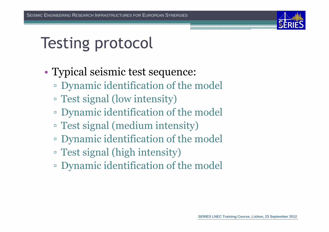
Testing protocol
• Typical seismic test sequence:
▫ Dynamic identification of the model
▫ Test signal (low intensity)
▫ Dynamic identification of the model
▫ Test signal (medium intensity)
▫ Dynamic identification of the model
▫ Test signal (high intensity)
▫ Dynamic identification of the model

SEISMIC ENGINEERING RESEARCH INFRASTRUCTURES FOR EUROPEAN SYNERGIES
SERIES LNEC Training Course, Lisbon, 23 September 2012
Shaking table operation
• LNEC large 3D shaking table characteristics:
▫ Maximum payload of 40tonnes
▫ Three independent axes (Transverse, Vertical, Longitudinal)
� Displacements controlled actively (actuators)
� Rotations passively restrained (torque tubes)
▫ Nominal stroke of 200mm
▫ Nominal peak velocity of 70cm/s
▫ Nominal peak acceleration depends on the mass of the model and the type of signal

SEISMIC ENGINEERING RESEARCH INFRASTRUCTURES FOR EUROPEAN SYNERGIES
SERIES LNEC Training Course, Lisbon, 23 September 2012
Shaking table operation
• The operation of the shaking table results from a combination of:
▫ Mechanical components
▫ Hydraulic components
▫ Electrical components
▫ Control algorithms

SEISMIC ENGINEERING RESEARCH INFRASTRUCTURES FOR EUROPEAN SYNERGIES
SERIES LNEC Training Course, Lisbon, 23 September 2012
Shaking table operation
• Mechanical components:
▫ Actuators
▫ Struts
▫ Swivels
▫ Torque tubes

SEISMIC ENGINEERING RESEARCH INFRASTRUCTURES FOR EUROPEAN SYNERGIES
SERIES LNEC Training Course, Lisbon, 23 September 2012
Shaking table operation
• Hydraulic components:
▫ Pipe lines
▫ Accumulator banks
• Electrical components
▫ Power supply
▫ Switch gear
▫ Pumps
▫ Substations

SEISMIC ENGINEERING RESEARCH INFRASTRUCTURES FOR EUROPEAN SYNERGIES
SERIES LNEC Training Course, Lisbon, 23 September 2012
Shaking table operation
• Control algorithms:
▫ Proportional–Integral–Derivative controller (PID controller) in the inner loop
▫ Shaking table tuning process on the outer loop
• The outer loop has been developed in LabVIEW and runs in a standard PC system;
• The inner loop (PID controller) runs in three dedicated FPGA boards connected to a LabVIEW Real Time PXI system

SEISMIC ENGINEERING RESEARCH INFRASTRUCTURES FOR EUROPEAN SYNERGIES
SERIES LNEC Training Course, Lisbon, 23 September 2012

SEISMIC ENGINEERING RESEARCH INFRASTRUCTURES FOR EUROPEAN SYNERGIES
SERIES LNEC Training Course, Lisbon, 23 September 2012
Shaking table control
• The PID controller calculation involves three separate constants:
▫ The Proportional value (P) depends on the present error
▫ The Integral value (I) depends on the accumulation of past errors
▫ The Derivative value (D) is a prediction of future errors based on current rate of change
• The weighted sum of these three actions is used to adjust the process via a control element.

SEISMIC ENGINEERING RESEARCH INFRASTRUCTURES FOR EUROPEAN SYNERGIES
SERIES LNEC Training Course, Lisbon, 23 September 2012
Shaking table operation
• The control loop feedback mechanism (controller):
▫ Calculates an “error” value as the difference between a measured process (y) and a desired setpoint (u)
▫ The controller attempts to minimize the error by adjusting the process control inputs.

SEISMIC ENGINEERING RESEARCH INFRASTRUCTURES FOR EUROPEAN SYNERGIES
SERIES LNEC Training Course, Lisbon, 23 September 2012
Shaking table control
• PID real time servo controller carried in FPGA boards:
)(teK p ×
∫×t
i deK0
)( ττ
dt
tdeKd
)(×
Σ Σ)(tu
+
Shaking table
)(ty
-
+
++
Feedback signal
)(te
SEISMIC ENGINEERING RESEARCH INFRASTRUCTURES FOR EUROPEAN SYNERGIES
SERIES LNEC Training Course, Lisbon, 23 September 2012
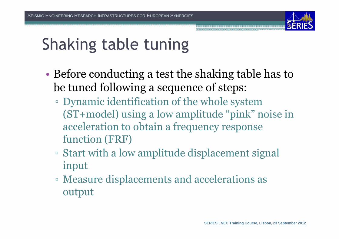
Shaking table tuning
• Before conducting a test the shaking table has to be tuned following a sequence of steps:
▫ Dynamic identification of the whole system (ST+model) using a low amplitude “pink” noise in acceleration to obtain a frequency response function (FRF)
▫ Start with a low amplitude displacement signal input
▫ Measure displacements and accelerations as output
SEISMIC ENGINEERING RESEARCH INFRASTRUCTURES FOR EUROPEAN SYNERGIES
SERIES LNEC Training Course, Lisbon, 23 September 2012
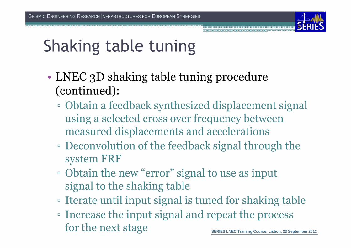
Shaking table tuning
• LNEC 3D shaking table tuning procedure (continued):
▫ Obtain a feedback synthesized displacement signal using a selected cross over frequency between measured displacements and accelerations
▫ Deconvolution of the feedback signal through the system FRF
▫ Obtain the new “error” signal to use as input signal to the shaking table
▫ Iterate until input signal is tuned for shaking table
▫ Increase the input signal and repeat the process for the next stage
SEISMIC ENGINEERING RESEARCH INFRASTRUCTURES FOR EUROPEAN SYNERGIES
SERIES LNEC Training Course, Lisbon, 23 September 2012
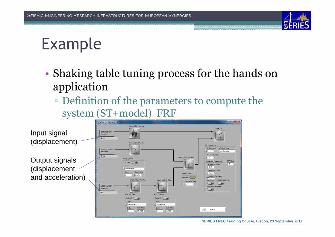
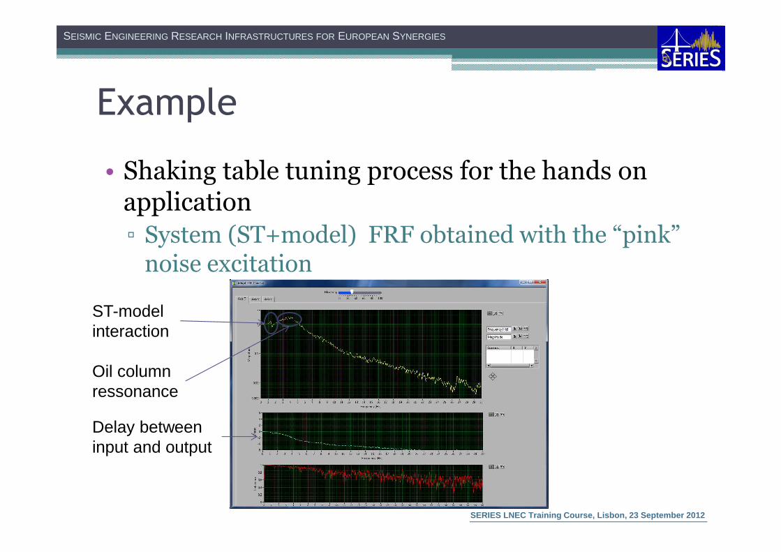
Example
• Shaking table tuning process for the hands on application
▫ Definition of the parameters to compute the system (ST+model) FRF
Input signal (displacement)
Output signals (displacement and acceleration)
SEISMIC ENGINEERING RESEARCH INFRASTRUCTURES FOR EUROPEAN SYNERGIES
SERIES LNEC Training Course, Lisbon, 23 September 2012
Example
• Shaking table tuning process for the hands on application
▫ System (ST+model) FRF obtained with the “pink” noise excitation
ST-model interaction
Oil column ressonance
Delay between input and output

SEISMIC ENGINEERING RESEARCH INFRASTRUCTURES FOR EUROPEAN SYNERGIES
SERIES LNEC Training Course, Lisbon, 23 September 2012
Example
• Shaking table tuning process for the hands on application
▫ Signal tuning iterative process
Previous drive
Next drive
Target signal
Inverse FRF deconvolution
Error correction factors
Error signal
Acquired signal

SEISMIC ENGINEERING RESEARCH INFRASTRUCTURES FOR EUROPEAN SYNERGIES
SERIES LNEC Training Course, Lisbon, 23 September 2012
Example
• Consider a target signal with a PGA of 0.2g and a correction factor of 65% in each iteration and 100% in the last one:
Drive Target Error Correction Acquired
0 0.2 0.2 0.65 0.13
1 0.2 0.07 0.65 0.1755
2 0.2 0.0245 0.65 0.191425
3 0.2 0.008575 1.00 0.2
SEISMIC ENGINEERING RESEARCH INFRASTRUCTURES FOR EUROPEAN SYNERGIES
SERIES LNEC Training Course, Lisbon, 23 September 2012
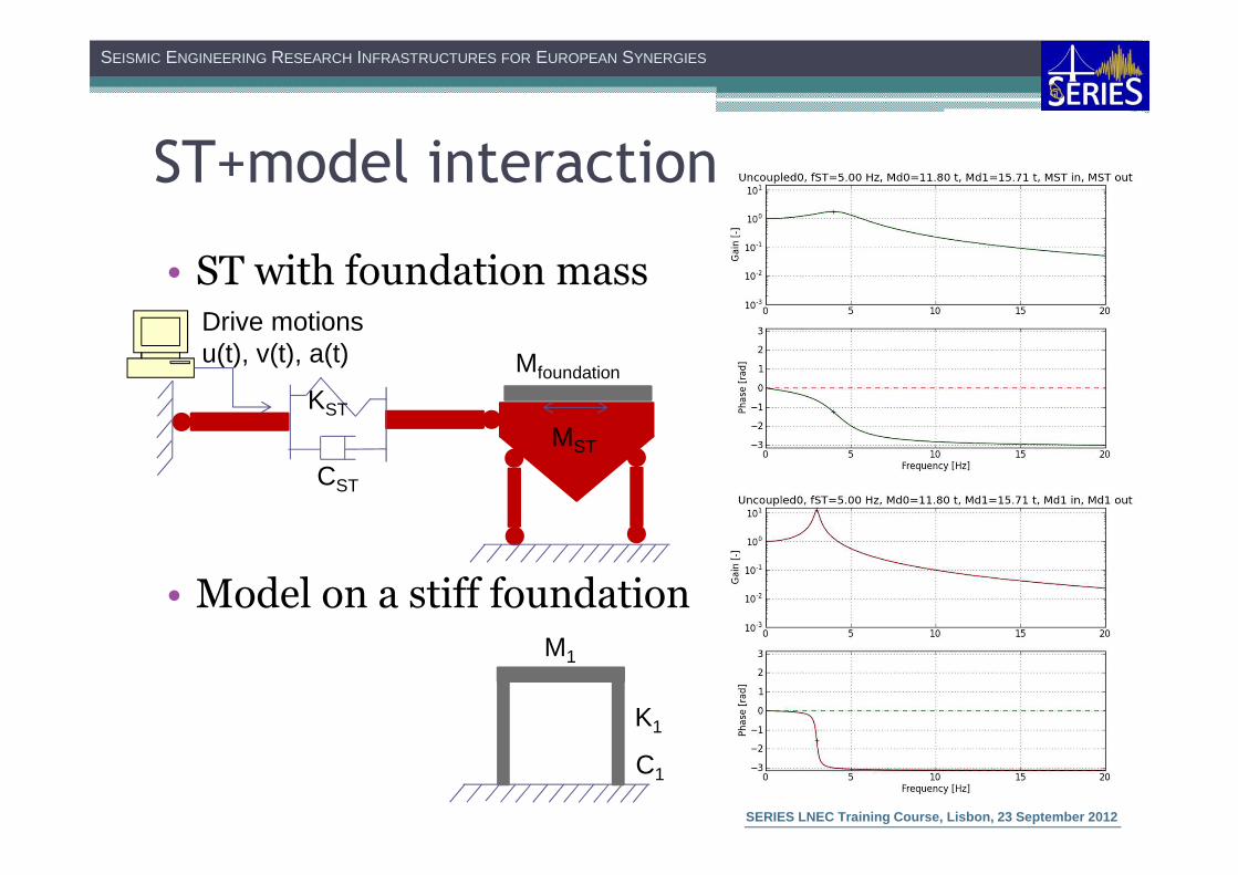
ST+model interaction
• ST with foundation mass
• Model on a stiff foundation
CST
KST
MST
M1
K1
C1
Drive motionsu(t), v(t), a(t) Mfoundation

SEISMIC ENGINEERING RESEARCH INFRASTRUCTURES FOR EUROPEAN SYNERGIES
SERIES LNEC Training Course, Lisbon, 23 September 2012
ST+model interaction
• Coupled (ST with model)
Drive motionsu(t), v(t), a(t)
CST
KST
MST
M1
K1
C1Mfoundation

SEISMIC ENGINEERING RESEARCH INFRASTRUCTURES FOR EUROPEAN SYNERGIES
SERIES LNEC Training Course, Lisbon, 23 September 2012
Example
• Numerical simulation in the longitudinal direction of the LNEC ST
▫ fST = 5.00Hz
▫ fmodel = 3.00 Hz
▫ Model foundation mass = 11.80 tonnes
▫ Model story mass = 15.71 tonnes
Frequency Uncoupled(ST with foundation mass)
Coupled(ST with model)
f1 (structural mode) 3.00 Hz 2.71 Hz
f2 (ST mode) 4.39 Hz 4.87 Hz

SEISMIC ENGINEERING RESEARCH INFRASTRUCTURES FOR EUROPEAN SYNERGIES
SERIES LNEC Training Course, Lisbon, 23 September 2012
References
• Harry G. Harris, Gajanan Sabnis, “Structural Modeling and Experimental Techniques”, Second Edition
• E. C. Carvalho, “Invited lecture: Seismic testing of structures”, 11ECEE

SEISMIC ENGINEERING RESEARCH INFRASTRUCTURES FOR EUROPEAN SYNERGIES
SERIES LNEC Training Course, Lisbon, 23 September 2012
Thank you for your attention!
![QUEENSLAND UNIVERSITY OF TECHNOLOGY BRISBANE, AUSTRALIA · Microsoft PowerPoint - SS1-1_Role of Research Infrastructures in Seismic Rehabilitation.ppt [Compatibility Mode] Author:](https://cdn.vdocument.in/doc/165x107/60e1fb9ec1bd1749507dae13/queensland-university-of-technology-brisbane-australia-microsoft-powerpoint-ss1-1role.jpg)

![SEISMIC ENGINEERING RESEARCH INFRASTRUCTURES FOR EUROPEAN ... · SEISMIC ENGINEERING RESEARCH INFRASTRUCTURES FOR EUROPEAN SYNERGIES Work package [WP9 – TA5 LNEC] THE LNEC EARTHQUAKE](https://cdn.vdocument.in/doc/165x107/5c15436709d3f2256b8d10f5/seismic-engineering-research-infrastructures-for-european-seismic-engineering.jpg)


