
Bomb Blast Resistant Structure________________________________________________________________________
A
SEMINAR REPORT
On
” BOMB BLAST RESISTENT STRUCTURE ”
SUBMITTED BY
Mr. SHANTANU SANJAY PATIL
DEPARTMENT OF CIVIL ENGINEERING
S.S.V.P.S.’s B.S.DEORE COLLEGE OF ENGINEERING,
DHULE- 424 0052014-2015
1
Bomb Blast Resistant Structure________________________________________________________________________
Chapter No.1
INTRODUCTION
The design of civilian or commercial buildings to withstand the
effects of a terrorist blast is unlike the design of military installations or
the design of embassy buildings. The objectives of the “Structural
Engineering Guidelines” for the Design of New Embassy Buildings are to
prevent heavy damage to components and structural collapse.
Adherence to the provisions of the guidelines will minimize injuries and
loss of life and facilitate the evacuation and rescue of survivors. The
blast-protection objective of any commercial or public building must be
similar to those of embassy structures, that is to prevent structural
collapse, to save lives, and to evacuate victims.
Architectural and structural features play a significant role in
determining how the building will respond to the blast loading. These
features can include adjacent or underground parking, atriums, transfer
girders, slab configurations, and structural-frame systems. The keep-out
distance is vital in the design of blast resistant structures since it is the
key parameter that determines the blast overpressures that load the
building and its structural elements. The degree of fenestration is another
key parameter as it determines the pressures that enter the structure.
The smaller the door and window openings the Embassies and military
structures occupy secure sites with substantial keep-out distances better
protected the occupants are within the structure.
2
Bomb Blast Resistant Structure________________________________________________________________________
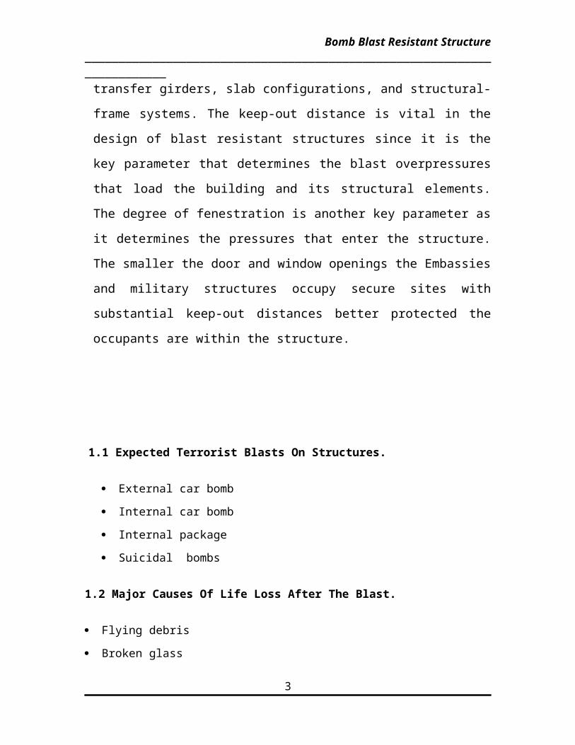
1.1 Expected Terrorist Blasts On Structures.
External car bomb
Internal car bomb
Internal package
Suicidal bombs
1.2 Major Causes Of Life Loss After The Blast.
Flying debris
Broken glass
Smoke and fire
Blocked glass
Power loss
Communications breakdown
Progressive collapse of structure
1.3. Goals Of Blast Resistant Design
The goals of blast-resistant design are to:
Reduce the severity of injury
Facilitate rescue
Expedite repair
Accelerate the speed of return to full operations.
Chapter No.2
3

Bomb Blast Resistant Structure________________________________________________________________________
DESIGN CONSIDERATION
2. 1 Structural Engineering
Structural engineering, or structural design, is the design of a building's
internal support system. Structural design includes the selection of a framing
method or structural system, as well as the selection and sizing of structural
members, based on loading and architectural requirements. Structural members
include beams, columns, the foundation, floor slabs, connections of these
elements to each other, and other ancillary components.
Building design (structural and architectural) can contribute to
infrastructure security by minimizing the extent and depth of damage in an attack.
Structural integrity can help mitigate blast and fire damage to the building; protect
inhabitants; protect equipment, property, and records; allow critical operations to
function immediately after an attack; and allow rescue operations in and around
the building preserved after an attack.
This section focuses on blasts and fires, describing engineering concepts for
structural integrity and strategies for minimizing damage. The concepts
discussed include:
Blast loads
Blast damage
Progressive collapse
Blast mitigation
The sections of most building codes relating to structural components
address service loads and methods to determine the proper size of structural
members and their connections. Service loads specified in building codes are
based on the location and intended use of the proposed structure, and include:
Minimum dead load: the weight of the structure
4

Bomb Blast Resistant Structure________________________________________________________________________
Live load: variable loads such as people, cars, furniture, etc.
Earth load: earth pressure on buried structures, retaining walls,
foundations, etc.
Wind load: pressure applied to the structure by wind
Snow load: the weight of snow on a building
Seismic load: loads induced on structural members during an earthquake
Building codes do not usually address "blast loads"; the force exerted on a
building from the detonation of an explosive device.
Blast loads are different from the usual types of service loads considered
by a structural engineer when designing a building. Service loads are relatively
predictable in their magnitude and placement on the structure. In contrast, blast
loads are much greater in magnitude, are unpredictable in size and placement.
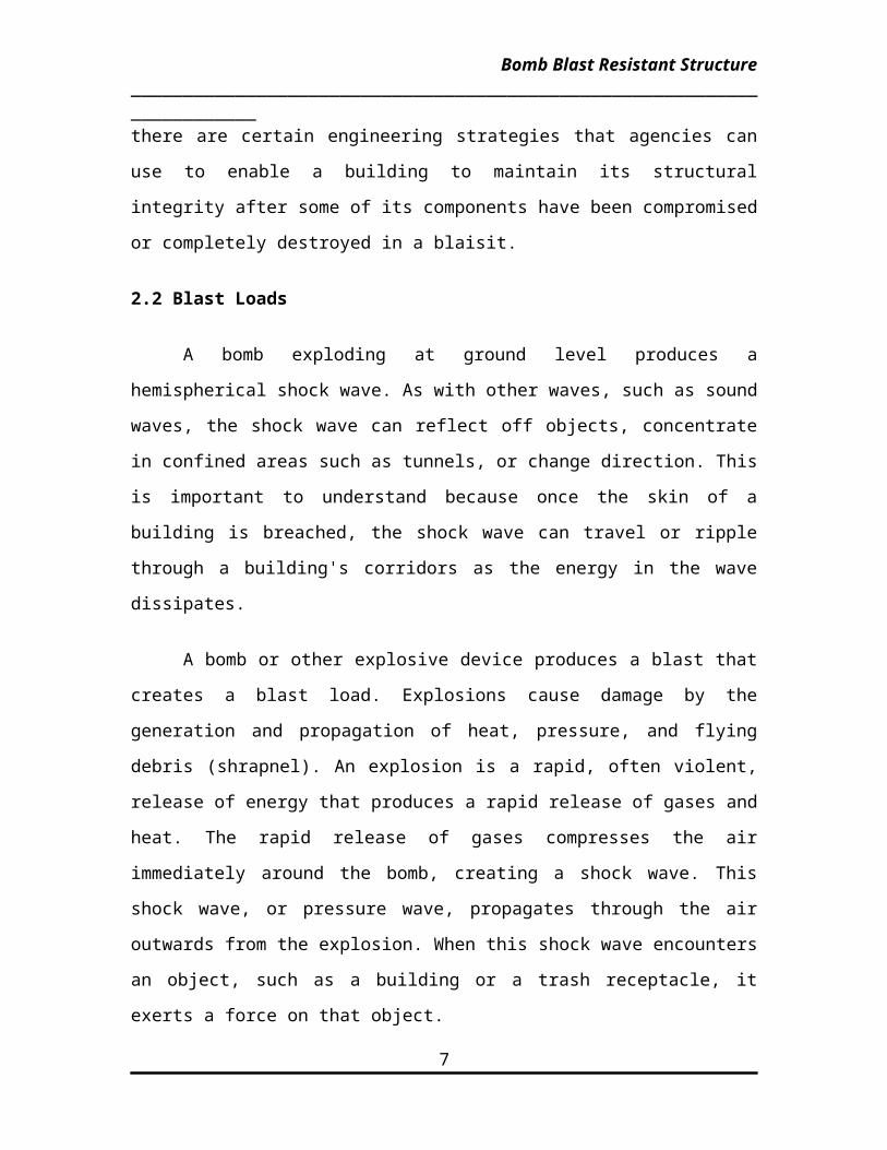
However, there are certain engineering strategies that agencies can use to
enable a building to maintain its structural integrity after some of its components
have been compromised or completely destroyed in a blaisit.
2.2 Blast Loads
A bomb exploding at ground level produces a hemispherical shock wave.
As with other waves, such as sound waves, the shock wave can reflect off
objects, concentrate in confined areas such as tunnels, or change direction. This
is important to understand because once the skin of a building is breached, the
shock wave can travel or ripple through a building's corridors as the energy in the
wave dissipates.
A bomb or other explosive device produces a blast that creates a blast
load. Explosions cause damage by the generation and propagation of heat,
pressure, and flying debris (shrapnel). An explosion is a rapid, often violent,
release of energy that produces a rapid release of gases and heat. The rapid
release of gases compresses the air immediately around the bomb, creating a
shock wave. This shock wave, or pressure wave, propagates through the air
5

Bomb Blast Resistant Structure________________________________________________________________________
outwards from the explosion. When this shock wave encounters an object, such
as a building or a trash receptacle, it exerts a force on that object.
Table Peak reflected overpressure (MPa) with different W-R combination
W R
100kgTNT
500kg TNT
1 tonTNT
2 tonTNT
1m 165.8 354.5 464.5 602.9
2.5m 34.2 89.4 130.8 188.4
5m 6.65 24.8 39.5 60.19
10m 0.85 4.25 8.15 14.7
15m 0.27 1.25 2.53 5.01
20m 0.14 0.54 1.06 2.13
25m 0.09 0.29 0.55 1.08
30m 0.06 0.19 0.33 0.63
The blast load striking a building or other object depends on the amount
and quality of explosive detonated and the distance of the explosion from the
building. Maximizing standoff distances is important; the farther away an
explosion, the weaker its effects. As the shockwave radiates away from the
explosion, the magnitude of the shockwave decreases and the duration of the
shockwave increases
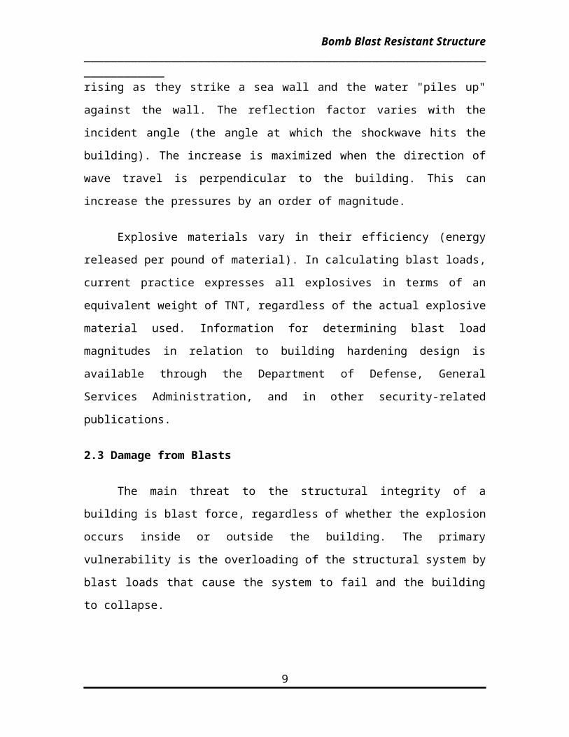
The peak magnitude of the shockwave increases by a reflection factor as
it encounters the face of a building. This increase in magnitude is analogous to
ocean waves rising as they strike a sea wall and the water "piles up" against the
wall. The reflection factor varies with the incident angle (the angle at which the
shockwave hits the building). The increase is maximized when the direction of
6
Bomb Blast Resistant Structure________________________________________________________________________
wave travel is perpendicular to the building. This can increase the pressures by
an order of magnitude.
Explosive materials vary in their efficiency (energy released per pound of
material). In calculating blast loads, current practice expresses all explosives in
terms of an equivalent weight of TNT, regardless of the actual explosive material
used. Information for determining blast load magnitudes in relation to building
hardening design is available through the Department of Defense, General
Services Administration, and in other security-related publications.
2.3 Damage from Blasts
The main threat to the structural integrity of a building is blast force,
regardless of whether the explosion occurs inside or outside the building. The
primary vulnerability is the overloading of the structural system by blast loads that
cause the system to fail and the building to collapse.
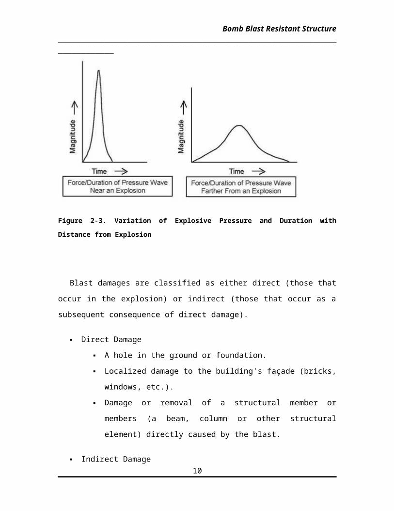
Figure 2-3. Variation of Explosive Pressure and Duration with Distance from Explosion
7

Bomb Blast Resistant Structure________________________________________________________________________
Blast damages are classified as either direct (those that occur in the
explosion) or indirect (those that occur as a subsequent consequence of direct
damage).
Direct Damage
A hole in the ground or foundation.
Localized damage to the building's façade (bricks, windows, etc.).
Damage or removal of a structural member or members (a beam,
column or other structural element) directly caused by the blast.
Indirect Damage
Flying shards of glass: Glass shards thrown from a window can
cause serious injury to people, even if they are several feet from
the window that shattered.
Progressive collapse: If a blast directly destroys a column or beam
locally, other structural members may fail. This can start a chain
reaction of failures that results in damage disproportionate to the
blast and collapse of the entire building.
2.4 Progressive Collapse
The worst-case consequence of blast damage related to structural engineering is
progressive collapse. This is the disproportionately large collapse of a building or
structure from an explosion, caused by the loss of one or more structural
members, resulting in only localized damage. Progressive collapse occurs
because most buildings are designed to carry the required loads, based on the
assumption that all structural members are in place.
Two types of progressive collapse are possible:
Pancaking is the stacking of floors on top of each other. It occurs when an
explosion destroys a structural member or members, causing the floor
8
Bomb Blast Resistant Structure________________________________________________________________________
directly above the destroyed members to collapse, which causes the next
floor above it to collapse, and so on.
Cascading is the collapsing of a series of bays (the section of a building
between two rows of columns) from the destruction of one or a few bays.
Cascading occurs when an explosion destroys a bay, or bays, causing the
adjacent bay or bays to collapse in succession.
Net upward pressure on slab
Fig. Progressive collapse
9
Bomb Blast Resistant Structure________________________________________________________________________
Chapter No.3
DESIGN TECHNIQUES
3.1 General Description Of Loading Requirements
To resist blast loads, the first requirement in the assessment of a structure
is to determine the threat. While numerous threats exist, the present seminar will
be limited to intentional explosions, such as those caused by terrorist bombings.
In recent terrorist attacks, the explosive device was a mixture of Ammonium
Nitrate and Fuel Oil (ANFO). These ingredients and detonating devices can be
purchased relatively easily; however there are many other types of explosive
devices, including TNT, C-4, and Semtex, which are more efficient and must be
considered. To standardize the criteria, the industry refers to the charge weight of
an explosive device in terms of equivalent TNT weight. The relative effect on
pressure and impulse can be scaled to an equivalent amount of TNT.
The threat for a conventional bomb is defined by two equally important
elements, the bomb size, or charge weight, and the standoff distance, the
minimum guaranteed distance between the blast source and the target. As
terrorist attacks range from the small letter bomb to the gigantic truck bomb as
experienced in Oklahoma City, the mechanics of a conventional explosion and
their effects on a target must be addressed. With the detonation of a mass of
TNT at or near the ground surface, the peak blast pressures resulting from this
hemispherical explosion decay as a function of the distance from the source as
the ever-expanding shock front dissipates with range. The incident peak
pressures are amplified by a reflection factor as the shock wave encounters an
object or structure in its path. Except for specific focusing of high intensity shock
waves at near 45° incidence, these reflection factors are typically greatest for
normal incidence (a surface adjacent and perpendicular to the source) and
diminish with the angle of obliquity or angular position relative to the source.
Reflection factors depend on the intensity of the shock wave, and for large
10

Bomb Blast Resistant Structure________________________________________________________________________
explosives at normal incidence these reflection factors may enhance the incident
pressures by as much as an order of magnitude.
The duration of the positive-phase blast wave increases with range,
resulting in a lower-amplitude, longer-duration shock pulse the further a target
structure is situated from the burst. Charges situated extremely close to a target
structure impose a highly impulsive, high intensity pressure load over a localized
region of the structure; charges situated further away produce a lower-intensity,
longer-duration uniform pressure distribution over the entire structure. In short, by
purely geometrical relations, the larger the standoff, the more uniform the
pressure distribution over the surface of the target. Eventually, the entire
structure is engulfed in the shock wave, with reflection and diffraction effects
creating focusing and shadow zones in a complex pattern around the structure.
Following the initial blast wave, the structure is subjected to a negative pressure,
suction phase and eventually to the quasi-static blast wind. During this phase,
the weakened structure may be subjected to impact by debris that may cause
additional damage.
While it may be possible to predict effects of a certain charge weight at a
specified standoff distance, the actual charge weight of explosive used by the
terrorist, the efficiency of the chemical reaction and the source location are not
reliably predictable. The most significant observation that one draws from blast-
pressure phenomenology is that the most effective means of protecting a
structure is to keep the bomb as far away as possible, by maximizing the keepout
distance. No matter what size the bomb, the damage will be less severe the
further the target is from the source. The external explosive threat is by no
means the only type of terrorist attack, but for the purpose of the present paper
an uncased bomb at street level is assumed.
Structural hardening should actually be the last resort in protecting a
structure; detection and prevention must remain the first line of defense. As the
cost of protection increases dramatically with the assumed charge weight, to the
11

Bomb Blast Resistant Structure________________________________________________________________________
point at which the cost of protection becomes untenable, and since the size of
the potential threat is such an unknown quantity, the structural engineer is put in
a very uncharacteristic role. Rather than designing to a specific charge weight, as
one would a live load or 50-year wind load that has a presumed return period, the
structural engineer must design a structure to exhibit its best behavior in the
presence of a blast loading. The blast loading may originate from any point
around the perimeter of the structure-within the loading dock, the mail room, or
the lobby. The engineer must design and detail specific components to withstand
the various threats such that catastrophic failure and progressive collapse is
avoided and the rescue of victims may proceed unhindered. The recognition of
the localized intensity of the close-in blast and the inability to design the entire
structure to withstand this type of loading is the first step in prescribing the design
forces to be withstood.
3.2 External Treatments
The two parameters that most directly influence the blast environment that
the structure will be subjected to are the bomb's charge weight and the standoff
distance. Of these two, the only parameter that anyone has any control over is
the standoff distance, and this is primarily dictated by the site. Regardless of the
selected charge weight, the maximum attainable standoff or keep out distance
must be secured around the entire perimeter of the building.
For the building under consideration, it is clear that only the pubic sidewalk
around the building can be controlled to limit the standoff distance. Thus the
building is extremely vulnerable to unimpeded hand-delivered or car-bomb
attacks. The most directly affected building elements are the lower-floor facade
and structural members. Therefore, the site parameter and the exterior elements
at the lower floors require special attention.
12
Bomb Blast Resistant Structure________________________________________________________________________
Stand Off
The keep out distance, within which explosives-laden vehicles may not
penetrate, must be maximized and guaranteed. As we all know, the greater the
standoff distance, the more the blast forces will dissipate resulting in reduced
pressures on, and impulse imparted to, the building. Several recommendations
can be made to maintain and improve the standoff distance for the building.
1. The public parking lot at the corner of the building must be secured to
guarantee the prescribed keepout distance from the face of the structure.
Securing this parking lot means that all vehicles must be cleared, i.e., employee
owned or visually inspected, such as delivery trucks. Preferably, the parking lot
should be eliminated.
2. Street parking should not be permitted on the near side of the street, adjacent
to the building. However, the city typically gains large revenue from street parking
and might require annual fees from the owner to compensate for the losses.
3. An additional measure to reduce the chances of an attack would be to prevent
parking on the opposite side of the street. While this does not improve the keep
out distance, it could eliminate the "parked" bomb, thereby limiting bombings to
"park and run," drive-by, and suicide bombers. Unfortunately, as was the case
with the Oklahoma City Bombing, the truck laden with explosives was only
parked for approximately two minutes. Even in the most security-aware
environments, this may not be long enough to draw the attention of security
officers.
Note that the practical benefit of increasing the standoff depends on the charge
weight. If the charge weight is small, this measure will significantly reduce the
forces to a more manageable level. If the threat is a large charge weight, the
blast forces may overwhelm the structure despite the addition of nine or ten feet
to the standoff distance, and the measure may not significantly improve the
survivability of the occupants or the structure.
13
Bomb Blast Resistant Structure________________________________________________________________________
Lower Floor Exterior
The architectural design of the building of interest currently calls for
window glass around the first floor. Unless this area is constructed in reinforced
concrete, the damage to the lower floor structural elements and their connections
will be quite severe. Consequently, the injury to the lower floor inhabitants will be
equally severe, especially at these short standoffs. In general, three sizes of
charges can be discussed.
1. To protect against a small charge weight, a nominal 300 mm (12 in.) thick wall
with 0.3% steel doubly reinforced in both directions might be required.
2. For intermediate charge weight protection, a 460 mm (18 in.) thick wall with
0.5% steel might be needed.
3. Finally, a large charge weight at these small standoffs will likely breach any
reasonably sized wall at the lower levels. Therefore, precautions have to be
taken and adjustments made for the design of the entire structure.
3.3 Glazing
Glazing has been described as the first weak link. It should be assumed
that all glazing on the target structure will fail for most realistic car bomb threats,
particularly on the side of the building facing the bomb. Commonly used
annealed glass behaves poorly when loaded dynamically. The failure mode for
annealed glass creates large sharp edged shards, resembling knives and
daggers. Historically, failed window glazing due to the direct pressures produced
by an explosion has resulted in a considerable proportion of the injuries and
casualties. For the window assemblies to behave properly, the glazing, mullions,
and anchorage must all be capable of resisting the blast pressures and transfer
the loads to the adjacent structure.
14
Bomb Blast Resistant Structure________________________________________________________________________
While typical annealed plate glass is only capable of resisting, at most, 14
kPa (2 psi) of blast pressure, there exist several other types of glazing that can
resist some modest blast pressures. Thermally Tempered Glass (TTG) and
Polycarbonate layups can be made in sheets up to about l-in. thick and can resist
pressures up to about 200 to 275 kPa (30 to 40 psi). The true abilities of each of
these window types is highly dependent on the actual dimensions. The greatest
benefit of TTG is the way that it fails. Unlike annealed glass, TTG breaks into
rock-salt sized pieces that will inflict less injury on the occupants. TTG is used for
the side and rear windows of automobiles. The failed Polycarbonate glass
unfortunately remains in one piece, similar to the windshield of a car, and can
cause injury similar to a large flying object. Equally important to the design of the
glass is the design of the attachments. For the window to fail properly, it must be
held in place long enough to develop the proper stresses that cause failure. Short
of that, the window would dislodge from the housing intact and cause serious
damage or injury. Unfortunately, as the pressures on the window get large, the
thickness of the supporting wall also drastically increases.
Attaining that delicate balance between adequate protection and properly
distributing blast-construction funds can become challenging. The cost
associated with blast-resistant walls and glazing can be expensive, despite the
fact that it is unlikely the windows will survive any sizable terrorist blast.
3.4 Facade And Atrium
As the building's exterior is its first real defense against the effects of a
bomb, how the facade responds to this loading will significantly effect the
behavior of the structure. The facade is comprised of the glazing and the exterior
wall. The glazing, a pressure sensitive element, is the first building component
likely to fail in response to the initial blast pressure that engulfs the building.
Although the wall may be hardened to resist the loading, the options available for
the glass are much more limited. Consequently, the windows will break easily
and the blast will enter the building causing additional damage and injury. There
15

Bomb Blast Resistant Structure________________________________________________________________________
exists a direct correlation between the degree of fenestration and the amount of
blast that is allowed to enter the occupied space. Limiting the amount of
fenestration will limit the blast effects.
Atriums are common in prestigious office buildings. This architectural
feature enhances the building's appearance not only by providing a grand
entrance, but also by bringing natural light into the work space and providing
impressive function spaces and balcony elevator lobbies. Atriums are inviting
targets; all the broken glass gives the appearance of extensive damage and
exposes many internal structural elements to blast loading. In the building
described above, the atrium has a large window at the building's exterior that
cannot be designed to withstand the blast pressures. Not only do fragments from
the failed glazing create a hazard, but the failed glazing allows the blast
overpressures to enter the interior of the building. Vented the blast deep into the
structure will result in multiple reflections that will increase the damage area and
cause more injury. If the atrium is extensive, providing a significant open space
relative to the size and shape of the structure, the blast pressures may even
attempt to split the building apart.
Exterior of Atrium
It is not reasonable to harden the exterior walls of the structure and leave
the atrium's exterior wall as an inviting target.
Therefore, these walls of glass must be redesigned to protect occupants
against a small charge or completely eliminated to protect occupants against a
moderate-size charge.
Interior of Atrium
Once within the structure, the blast waves will both dissipate with distance
and reflect off of the internal surfaces. The pressure distributions resulting from a
small charge opposite the plate-glass atrium facade exceed the nominal 14 kPa
16
Bomb Blast Resistant Structure________________________________________________________________________
(2 psi) capacity over its entire height, though, depending on the charge weight,
there will be a height above which the pressure is diminished to approximately
70-100 kPa (10-15 psi), a magnitude associated with a reduced likelihood of
human fatality. At this elevation and above, the overpressures that enter the
structure through the shattered glass facades will be reduced sufficiently to pose
a diminished threat to the occupants.
A moderate-size explosion opposite the glass facade, however, produces
dangerously large pressures in excess of 200 kPa (30 psi) over the entire height
of the structure. The shock waves entering the structure, and subsequent internal
reflections, would destroy internal partitions facing the atrium and pose a serious
threat to the occupants. The protection of the occupants from these pressures
can only be achieved by a reinforced concrete wall along the face of the building.
It must be reiterated that the small charge weight, as well as the medium charge
weight, do not correspond to a realistic threat scenario, and therefore decisions
to retain the glass facades would be made in spite of the historical precedent of
recent terrorist car bomb attacks.
To summarize, the presence of an atrium along the face of the structure
will require two protective measures. On the outside of the structure, the glass
and glass framing must be strengthened to withstand the loads. On the inside,
the balcony parapets, spandrel beams, and exposed slabs must be strengthened
to withstand the loads that enter through the shattered glass.
3.5 Floor Slabs
The reinforced-concrete flat-plate structural system supports the gravity
loads within the building. It is an economical solution, which provides for
maximum use of vertical space, particularly for buildings in areas with height
restriction. This allows for mechanical systems to pass unobstructed, and permits
easy forming and fabrication of the slab system. Note that the building, as
designed, does not require the use of drop panels or column capitals. The live
17
Bomb Blast Resistant Structure________________________________________________________________________
load requirements is typical throughout the building. Therefore, with the
exception of localized areas, the slab thickness and reinforcement requirements
remain the same for both interior and exterior bays of the building.
If this building is subjected to a blast load, the flat slab construction will be
exposed to a large dynamic pressure load. Punching shear and softening of the
moment-resisting capacity of the slabs will reduce the lateral-load-resisting
capacity of the system. Once the moment-resisting capacity of the slabs at the
columns is lost, the ability of the slab to transfer forces to the shear walls is
diminished and the structure is severely weakened. This may result in several
possible modes of failure, such as the following:
1. The slab itself may experience localized failure .
2. The loss of contact between the slab and the columns may increase the
unsupported column lengths, which may lead to the buckling of those columns.
epicts the case in which the slab column connection is weakened and the
unsupported length of the column is therefore significantly increased.
3. The lateral load resisting system, which consists of the shear walls, the
columns, and the slab diaphragms that transfer the lateral loads, may be
weakened to such an extent that the whole building may become laterally
unstable.Depicts a case in which the lateral load resisting system is dependent
on the presence of the slab. When the flat slab becomes unstable, the lateral
load resisting system will be degraded.
To avoid such calamity, the following improvements for conventional flat-
plate design must be considered:
1. More attention must be paid to the design and detailing of exterior bays and
lower floors, which are the most susceptible to blast loads .
18
Bomb Blast Resistant Structure________________________________________________________________________
2. Spandrel beams, which are included in the building but are not mandatory,
must be included to tie the structure together and enhance the response of the
slab edge.
3. In exterior bays/lower floors, drop panels and column capitols are required to
shorten the effective slab length and improve the punching shear resistance .
4. If vertical clearance is a problem, spearheads embedded in the slab will
improve the shear resistance and improve the ability of the slab to transfer
moments to the columns.
5. The ductility demands and shear capacity required to resist multiple-load
reversals often force the engineer to provide beams to span over critical sections
of the slab. The inclusion of beams will enhance greatly the ability of the framing
system to transfer lateral loads to the shear walls.
6. The slab-column interface should contain closed-hoop stirrup reinforcement
properly anchored around flexural bars within a prescribed distance from the
column face.
7. Bottom reinforcement must be provided continuous through the column. This
reinforcement serves to prevent brittle failure at the connection and provides an
alternate mechanism for developing shear transfer once the concrete has
punched through.
8. The development of membrane action in the slab, once the concrete has failed
at the column interface, provides a safety net for the postdamaged structure.
Continuously tied reinforcement, spanning both directions, must be detailed
properly to ensure that the tensile forces can be developed at the lapped splices.
Anchorage of the reinforcement at the edge of the slab or at a structural
discontinuity is required to guarantee the development of the tensile forces.
19
Bomb Blast Resistant Structure________________________________________________________________________
In all, the slab should be designed to prevent a punching shear failure that
in turn develops into a progressive collapse. Although Hawkins and Mitchell have
shown that punching shear failures at interior columns are more likely to result in
a progressive collapse than a failure at an exterior column, for the external bomb
threat, the external bay around the perimeter of the structure must be hardened
at all intersecting columns.
3.6 Columns
The columns of the typical building were primarily designed to resist
gravity loads in which no special accounting for ductility demands has been
taken. For blast consideration, the distance from the explosion determines, to a
great extent, the characteristics of the loading on the structure. Two different
scenarios can be considered.
1. Buildings situated at a substantial distance from a protected perimeter
approximately 30 m (100 ft) or more will be exposed to relatively low pressures
fairly uniformly distributed over the facade. This 30 m (100 ft) enforced standoff,
keep-out distance, is one of the basic tenets of the DOS-FBO guidelines
2. Buildings that are situated less than 30 m (100 ft) from the curb will be
exposed to more localized, higher intensity blast pressures. In an urban setting,
such as the typical building under consideration and the Oklahoma City incident,
where large keep-out distances are unattainable, this is the prevalent scenario.
It is clear that special treatment of the columns is required if this building it is to
resist blast effects. The direct blast pressure will result in severe bending of the
column, in addition to the axial loads that it supports. The column will require
sufficient ductility to sustain the combined effects of axial load and lateral
displacement.
20
Bomb Blast Resistant Structure________________________________________________________________________
Furthermore, the blast pressures that enter the structure through the
shattered windows and failed curtain walls will load the underside and
subsequently the top surfaces of the floor slabs along the height of the building.
Both the delay in the sequence of loading and the difference in magnitude of
loading will determine the net pressures acting on the slabs. Consequently, there
will be a brief time for which each floor will receive a net upward loading. This
upward load requires that the slab be reinforced to resist loads opposing the
effects of gravity. Furthermore, it is possible that the uplift, the net upward load
on the slab, will result in a brief tensile force in the columns. Conventional
reinforced concrete columns, such as those in this building, are not designed to
resist the combined effects of bending and tension and may therefore be prone
to damage under these conditions. shows a schematic representation of this
uplift phenomenon.
Given all the limitations of the conventionally designed columns,
adaptation of one or more of the following recommendations will improve the
blast-resisting mechanism:
1. The potential for direct lateral loading on the face of the columns, resulting
from the blast pressure and impact of explosive debris, requires that the lower-
floor columns be designed with adequate ductility and strength .
2. The perimeter columns supporting the lower floors must also be designed to
resist this extreme blast effect .
3. Encasing these lower-floor columns in a steel jacket will provide confinement,
increase shear capacity, and improve the columns' ductility and strength. An
alternative, which provides similar benefits, is to embed a steel column within the
perimeter concrete columns or wall section.
4. The possibility of uplift must be considered, and, if deemed likely, the columns
must be reinforced to withstand a transient tensile force.
21

Bomb Blast Resistant Structure________________________________________________________________________
5. For smaller charge weights, spiral reinforcement provides a measure of core
confinement that greatly improves the capacity and the behavior of the reinforced
concrete columns under extreme load.
3.7 Transfer Girders
The building relies on transfer girders at the top of the atrium to distribute
the loads of the columns above the atrium to the adjacent columns outside the
atrium. The transfer girder spans the width of the atrium, which insures a column-
free architectural space for the entrance to the building.
The presence of transfer girders in a blast-designed building must be
handled with utmost care. Transfer girders typically concentrate the load-bearing
system into a smaller number of structural elements. This load-transfer system
runs contrary to the concept of redundancy desired in a blast environment. A
blast that might adversely affect the transfer girder may end up affecting the
whole building in a progressive collapse mechanism. The column connections,
which support the transfer girders, are to provide sustained strength despite
inelastic deformations. If transfer girders are to be used in the building , the
following recommendations must be met:
1. The transfer girder and the column connections must be properly designed
and detailed, using an adequate blast loading description.
2. A progressive-collapse analysis must be performed, particularly if the blast
loading exceeds the capacity of the girder
3.8 Internal Explosion Threats
The blast environment could be introduced into the interior of the structure
in four vulnerable locations: the entrance lobby, the basement mechanical rooms,
the loading dock, and the primary mail rooms . These are areas where
unsecured packages can be delivered with little forewarning. Specific
22
Bomb Blast Resistant Structure________________________________________________________________________
modifications to the features of these unprotected spaces can prevent an internal
explosion from causing extensive damage and injury inside the building. The
following structural modifications to the building under consideration are
recommended:
1. Walls and slabs adjacent to the lobby, loading dock, and mail rooms must be
hardened to protect against the hand delivered package bomb, nominally a 10-20
kg (25-50 lb) explosive. Hardening these internal spaces will help confine the
explosion and prevent the spread of extensive internal damage or injuries. This
hardening can be achieved by redesigning the slabs and erecting cast-in-place
reinforced-concrete walls, with the thickness and reinforcement determined
relative to the appropriate threat.
2. The basement must be similarly isolated from all adjacent occupied office
space, including the floor above, from the threat of a small package bomb.
3. Any other unsecured spaces in which package bombs may be detonated must
be similarly isolated. This would include protecting any occupied office space,
mechanical rooms, or utility feed rooms located adjacent to an unsecured
underground parking garage.
23
Bomb Blast Resistant Structure________________________________________________________________________
Chapter 4
FIRE PROTECTION
While accidental fires may occur, fires resulting from an attack may have a
different kind of impact. For example, an accidental fire usually starts at one
location and often, but not always, spreads relatively slowly. On the other hand, a
fire from arson is often strategically set in multiple locations to maximize the rate
of spread and damage. An arsonist may also sabotage the fire protection system.
An incendiary bomb that produces a fireball or intense heat (as opposed to a
bomb that produces only a shock wave) ignites a large area and can cause
substantial damage, including local damage to the fire suppression system.
Well-established design and construction practices for protecting structural
members from fire are particularly important in case of an attack. Although not all
structural materials will "burn," all structural members, regardless of their material
composition, will lose a percentage of their original strength when subjected to
intense heat. Excessive heat is the principal cause of a fire's detrimental effects
on a structure. Therefore, upgrading or hardening the automatic sprinkler system
is of tremendous benefit in mitigating the effects of fire on a structure.
Additionally, many of the mitigation measures for blast impacts apply to fire
management as well, such as isolating vulnerable areas to prevent the spread of
fire and avoiding progressive collapse This section discusses the effects of fire
on four major structural construction materials: steel (structural steel), reinforced
concrete, pre-stressed concrete, and timber.
4.1 Steel
At high temperatures, unprotected steel looses its strength. For this reason
structural steel members used in building construction are protected
(fireproofed). Fireproofing methods to protect steel members from heat insulate
24

Bomb Blast Resistant Structure________________________________________________________________________
the steel from the fire. This increases the time required for heat to transfer from
the fire to the steel.
There are several insulating methods for steel members:
Concrete encasement. Encasing steel members in concrete
provides excellent insulation to the steel. Lightweight concrete
provides better insulation than standard concrete. The selection of
concrete type depends on several design factors that are beyond
the scope of this document. This method is well suited to
insulating columns. It may also be used to insulate floor beams
supporting a concrete floor slab. However this can be expensive
due to complicated forming and increased dead load.
Sprayed on mineral fiber coatings. Mineral fiber coatings are easy
to apply, and they provide excellent protection when applied
correctly. However, these coatings are easy to scrape off, and
explosive blasts may damage portions of the insulation. Protection
of the insulation is discussed at the end of this section.
Cementitious material coatings. Cementitious coatings form a
continuous coating around the steel. However, during a fire, they
can spall (chip or flake on the surface), and there is a history of
problems with lack of adhesion to the steel.
Intumescent paints and coatings. Intumescent coatings swell
when heated, thereby insulating the steel and retarding the effects
of the flames and high temperatures. These coatings work well to
protect the steel from heat. Exposure to flames can damage or
destroy this type of coating and therefore should only be applied
to components unlikely to be directly exposed to flames.
There are several concerns when selecting a method to fireproof steel, including
method of building construction, and installation and maintenance costs. During a
blast, it is likely that the fire proofing on the steel in the immediate vicinity of the
25

Bomb Blast Resistant Structure________________________________________________________________________
blast will be damaged. However, the fire that may result (and spread) will have
an effect similar to conventional fires. Assuming the progressive collapse
considerations were used in design, protection of the remaining steel members
will be effective.
4.2 Reinforced Concrete
Concrete is often used as an insulating material. Although concrete structures
rarely collapse from fire damage, the strength of concrete and reinforced
concrete members is reduced by exposure to high temperatures. Type of
aggregate and moisture content are the principal factors that determine
concrete's sensitivity to heat.
Type of aggregate is the most significant factor. Lightweight aggregates such as
vermiculite and perlite are used in lightweight concrete. Lightweight concrete, in
addition to having better insulating characteristics, has better strength retention
when exposed to intense heat.
The amount of moisture in a concrete affects the member's resistance to heat.
The moisture is trapped in the small capillaries within the concrete. As heat
energy is absorbed, the water in the concrete vaporizes, which locally helps
maintain the concrete's strength until the moisture is burned off. However, voids
left by the vaporized moisture weakens the area. Structural engineers should
consider this when fire is a concern for concrete members.
4.3 Pre-Stressed Concrete
The relevance of aggregates and moisture content for pre-stressed concrete are
similar to those for reinforced concrete. The concrete used for pre-stressed
concrete members is usually stronger than the concrete used for reinforced
concrete members and has better fire resistance, but tends to spall and expose
the reinforcement.
26

Bomb Blast Resistant Structure________________________________________________________________________
Pre-stressing steel is the principal concern when exposing pre-stressed
members to intense heat. High carbon-cold drawn steel used in pre-stressing is
more sensitive to intense heat than low carbon, hot rolled steel used in reinforced
concrete. Also, the loss of strength in pre-stressing steel is permanent and not
regained upon cooling. For example, the pre-stressing steel is initially under
great tension. Over time this tension decreases, as the steel tends to creep
(continually deform or lengthen). This is taken into account during the design
process; however exposure to high temperatures, exacerbated by the spalling
concrete, accelerates this "creeping" process. Engineers should consider this
when considering fire effects on building hardening.
4.4 Timber
Unlike steel and concrete, wood will burn. The principal factors that determine
how timber responds during a fire are the size of the timber member and its
moisture content.
As wood burns, a charcoal layer forms on the wood's exterior. This char layer is
an insulator and as the layer thickens, it slows down the rate of burning. The
unburned interior wood retains its strength. Buildings constructed with large
timber members can maintain their integrity for a long time during a fire, providing
an opportunity for the fire to be extinguished before structural failure occurs. As is
in all cases, but especially for timber construction, a hardened sprinkler system is
important. Fire retardants can slow combustion and delay ignition of wooden
members
27
Bomb Blast Resistant Structure________________________________________________________________________
CONCLUSION
After studying the behaviour of building subjected to a blast loading,
different structural and architectural features of the building were analyzed, and
their vulnerability to blast loading was presented. Several techniques were
presented for each of the identified features. The implementation of these
techniques will greatly improve the blast – resisting capability of the building.
28
Bomb Blast Resistant Structure________________________________________________________________________
REFERENCES
1. Civil engineering journal (oct. 1995)
2. Fire engineering journal (nov. 1995)
3. Structural design and construction journal (nov. 1996)
4. American concrete institute American society of civil engineering
Committee 352 (1985).
5. www.structuremag.org
6. www.berkley.edu
7. www.sciam.com
8. www.civil.usyd.edu
29


