
Final Report 2014 | Executive Summary 0
Raymond S Pell
Construction Management Option
Faculty Advisor: Robert Leicht
Submitted: April 9, 2014
Senior Thesis
Final Report
2014
Senior Thesis
Final Report
2014

Final Report 2014 | Executive Summary 1
Executive Summary
This Senior Thesis Final Report intends to present analyses of three aspects of the Central Ohio
Elementary School renovation/addition project. The 140 year old school was damaged by fire
and forced to close. A recent availability of funding has allowed the school to undergo a
complete restoration and the addition of more modern facilities. The areas of analyses include
photo documentation, structural modification and alternate plumbing materials.
Analysis 1: Use of Multivista Construction Documentation
The project uses a third-party photo documentation service to visually document the
construction process from pre-build site conditions to project completion. The service is an
additional cost incurred by the owner. This analysis investigates the benefits of a service such
as this and analyzes the potential monetary return.
Analysis 2: Use of Steel Deck and Cast-In-Place Concrete
A portion of the project is new construction that will connect two existing buildings. Precast
hollow core planks will be used for the flooring system. Establishing accurate dimensions of the
space has been difficult as the aging structure does not provide level surfaces or consistently
straight walls from which to take the necessary measurements. The design of a steel deck and
cast-in-place concrete alternative would prove more flexible and therefore eliminate the
potential for delays associated with the production of replacement precast planks. Installation
of the deck and concrete will also benefit other trades as highly detailed coordination will not
be required as early in the project as is necessary with precast.
Analysis 3: Use of PEX Tubing for Domestic Plumbing
The plumbing system for this elementary school is designed using copper with soldered joints;
the industry standard for commercial construction. Time and monetary savings are a
consideration on every job and installing PEX instead of copper on this project can achieve
both. This analysis estimates the actual savings, compares the friction loss associated with both
systems and investigates the advantages and disadvantages of PEX.

Final Report 2014 | Table of Contents 2
Table of Contents Executive Summary ......................................................................................................................... 1
Table of Contents ............................................................................................................................ 2
Project Background ......................................................................................................................... 4
Analysis 1: Use of Multivista® Construction Documentation ......................................................... 7
Problem Identification ................................................................................................................ 7
Research Goal .............................................................................................................................. 7
Methodology ............................................................................................................................... 7
Background Information ............................................................................................................. 8
Case Study ................................................................................................................................. 11
Sample Situations ...................................................................................................................... 13
Vertical Reinforcement between Windows .......................................................................... 13
Copper Pipe Stolen................................................................................................................ 14
Window Leak ......................................................................................................................... 14
Cracked Wall ......................................................................................................................... 15
Ceiling Leak ........................................................................................................................... 15
Advantages and Disadvantages ................................................................................................ 15
Third-Party Photo Documentation Conclusion ......................................................................... 17
Analysis 2: Use of Steel Deck and Cast-In-Place Concrete ............................................................ 18
Problem Identification .............................................................................................................. 18
Research Goal ............................................................................................................................ 19
Methodology ............................................................................................................................. 20
Original Solution ........................................................................................................................ 20
Cast-in-Place Solution ............................................................................................................... 21
Cost and Schedule ..................................................................................................................... 21
Structural Breadth ..................................................................................................................... 22
Introduction .......................................................................................................................... 22
Calculations for Dead and Live Loads ................................................................................... 23
Calculations for Joist AB1 ...................................................................................................... 24
Flooring System Conclusion ...................................................................................................... 25

Final Report 2014 | Table of Contents 3
Analysis 3: Use of PEX Tubing for Domestic Plumbing ................................................................. 26
Problem Identification .............................................................................................................. 26
Research Goal ............................................................................................................................ 26
Methodology ............................................................................................................................. 26
Original Solution ........................................................................................................................ 26
PEX Solution .............................................................................................................................. 27
Cost & Schedule ........................................................................................................................ 27
Advantages and Disadvantages ................................................................................................ 30
Plumbing Breadth ...................................................................................................................... 31
Introduction .......................................................................................................................... 31
Calculations for 2” Type L Copper Pipe ................................................................................. 31
PEX Tubing Conclusion .............................................................................................................. 33
Conclusion ..................................................................................................................................... 34
Appendix A: Use of Steel Deck and Cast-In Place Concrete ......................................................... 35
Appendix B: Use of Pex Tubing for Domestic Plumbing ............................................................... 45
Appendix C: Table and Figure Index ............................................................................................. 59
Table Index ................................................................................................................................ 60
Figure Index ............................................................................................................................... 61
Appendix D: Acknowledgements .................................................................................................. 62
Appendix E: References ................................................................................................................ 65

Final Report 2014 | Project Background 4
Project Background
The project selected for use in this research project is an elementary school located in central
Ohio. The project consists of new construction and renovation work. The original building,
constructed in 1874, was damaged by fire. The building was subsequently closed and the
students were relocated to adjacent schools as the cost of repairs were deemed an
unnecessary expense.
A district-wide push toward the neighborhood school concept revitalized interest in reopening
the school. As funding became available, a plan to renovate the 28,000 square feet of existing
space and add 18,000 square feet of modern amenities was developed. The school is located at
the intersection of two historical districts, resulting in a compromised list of restrictions
affecting exterior materials, scale and setbacks and requiring special attention paid to the brick
alleyway.
The project consists of the abatement of hazardous materials, demolition of a portion of the
building, complete renovation of the remaining structure, construction of the addition,
completion of sitework and the demolition of an adjacent building. The construction costs are
$9.07 million. The total project costs, excluding demolishing the secondary building, are $11.2
million.
The design process began on July 5, 2011. After the lengthy approval process, construction
began on June 4, 2013. The substantial completion date is scheduled for 435 days later, on
August 13, 2014. Contract completion, January 23, 2015, follows winter commissioning.
Figure 1: Architect's rendering of the completed project. (Hardlines Design Company)

Final Report 2014 | Project Background 5
The existing buildings are comprised of three stories. The ground floor is partially below grade
but provides means of egress. The first floor is located entirely above grade and is the main
point of entrance. The structures also contain attic space that will be unoccupied.
The existing building is wrapped in limestone veneer and red brick. The stone architectural
features were preserved and if necessary repaired. The renovation will include new aluminum
window systems installed in the existing openings. The existing space will be used mainly for
classrooms and will also contain the cafeteria, restrooms, art room and offices. Some work will
be needed to repair the effects of the fire. This will mainly involve replacing the existing
flooring system in the rooms where the fire started with steel deck and cast-in-place concrete
supported by a wide flange beam and the masonry walls. The wood joist floors that survived
the fire will remain. The interior finishes will be replaced and the interior walls will be
reconfigured to better accommodate the needs of a modern educational facility.
The new construction mainly occurs to the north of the existing structure and does not include
attic space. This portion of the completed facility will include classrooms, the gymnasium, food
preparation and storage areas and mechanical rooms. One section of new construction is
located between the two existing structures and is referred to as the “Connector”. This section
of the building will house offices, storage, a classroom, the music room and the facilities
elevator.
The new exterior walls will be 8” CMU with limestone and brick to match the existing exterior
finishes. The windows will be more modern in style than those installed in the existing building.
The structure of the building will be a combination of CMU bearing walls and wide flange steel
members. Precast hollow core planks with a concrete topping will be used for the floors. Cold-
formed steel framing will be used for interior wall construction throughout the project.
Suspended ceilings will be installed in the offices, corridors, restrooms, classrooms and all other
student-oriented areas.
A majority of the heating and cooling will be accomplished using Variable Refrigerant Flow
(VRF) units. These units will provide room-specific conditioning while being more efficient than
traditional HVAC methods. Air handlers will be used to condition the gymnasium, cafeteria and
corridors.
Power is supplied to the building from a 500 KVA pad mounted transformer. The building’s
main switchboard is rated at 2000 Amps. An electrical closet is located on each floor. In the
case of a power outage, a 60KW natural gas generator will provide the facility’s emergency
electricity. Recessed fluorescent lights will be used throughout the building with the main
exceptions being the gymnasium, which will use suspended fluorescent fixtures and mechanical
rooms, which will use surface mounted fluorescent fixtures.

Final Report 2014 | Project Background 6
The delivery method for this project is Single Prime with CM advisor. The construction manager
has been participating since the project’s inception. Figure 2 shows the project’s organizational
structure.
Once completed, the school will provide a local solution for the educational needs of this
neighborhood. The 350 children in grades K-5 will no longer need to be bused to school each
day but will be able to walk to this new facility that has been meticulously renovated to
accommodate a modern learning environment.
Figure 2: Project organization diagram.

Final Report 2014 | Analysis 1: Use of Multivista® Construction Documentation 7
Analysis 1: Use of Multivista® Construction Documentation
Problem Identification
The viability of third party photographic construction documentation is analyzed in this section,
as this service is utilized at Central Ohio Elementary School with the purpose of providing the
owner with “visual as-builts” of the building.
As-built drawings are a crucial element of maintaining a building. Unfortunately, the owner is
at the mercy of the conscientiousness of the contractors as it pertains to their accuracy. While
the contractors are required to provide as-built drawings, they are sometimes rushed or
incomplete. Often any changes made to the drawings are recollected from notes or memory,
leaving open the possibility of a slightly inaccurate representation of what actually exists. The
presence of photographic documentation to substantiate or dispute the drawings can be a vital
tool.
Research Goal
The goal of this analysis is to research the viability of third-party photographic documentation.
A case study will be used to find advantages to this service. The research will also include a
background study of the particular service used on this project.
Methodology
Review Multivista Systems, LLC’s documentation to identify proposed benefits of the
service.
Interview Multivista contact to gain deeper insight into the service and obtain financial
evidence of benefits.
Interview Smoot Construction contacts to discuss benefits and shortcomings of the
documentation service on current projects.
Research the average cost of and time spent on investigatory procedures that could be
rendered obsolete by this service.
Compare cost of service to projected savings.

Final Report 2014 | Analysis 1: Use of Multivista® Construction Documentation 8
Background Information
The photographic documentation service for this project is being provided by Midwest
Documentation, the Ohio division of Multivista Systems, LLC (Multivista). The company
provides this service as well as construction webcams and construction and owner training
videos for projects in the United States, Canada and United Kingdom. Multivista was the only
company found to be offering photo documentation of this nature in Central Ohio.
Multivista’s service includes both
construction progress photography and
milestone documentation. The milestone
documentations are one-time photo shoots
providing an exact record of the construction
site at critical stages of the project. An
example of this type of shoot would be the
MEP Exact-Built® (Figure 3). This captures the
mechanical, electrical and plumbing systems
installed in the walls and ceilings following
inspection but before insulation and finishes
are installed. The progress photography is a
series of interior and exterior photos of the
project taken at regular intervals, usually
monthly, throughout the project’s duration.
These photos provide a visual timeline of the
project’s progress that can be later used to
identify hidden conditions or determine the
timeframe of specific work.
The service is typically contracted on a square foot pricing structure. The price per square foot
varies depending on the required number of milestone photo shoots and complication level of
the construction project (e.g., warehouses typically have a lower cost than hospitals). The cost
for a school similar to the one used for this research project would be approximately $0.20 per
square foot. This would translate into a contract cost of $9,443 for this 47,219 square foot
project.
The photographers are former tradesmen, not professional photographers. They are required
to have earned their 10- and 30-hour OSHA cards. The photographs are taken with wide angle
lenses using high megapixel cameras. The photographers are trained at the corporate
headquarters in Vancouver, British Columbia, Canada. When photographing any jobsite, the
photos are always taken in the same prescribed order, so as to ensure accuracy. Additionally,
Figure 3: Example of MEP milestone photo. (Multivista®)

Final Report 2014 | Analysis 1: Use of Multivista® Construction Documentation 9
taking pictures of workers is avoided when at all possible. These requirements and equipment
allow for the photographers to be safe, knowledgeable of the construction process,
comfortable on a construction site and able to avoid interference with ongoing work.
After the completion of a photo shoot, the photographs are accessible to the owner using
Multivista web-based software. Using an architect-provided floor plan, the photographs are
mapped to their location, seen in Figure 4. These photos are then available to anyone granted
permission by the owner.
Figure 4: Example floor plan viewed on Multivista web-based software. (Multivista®)
The software uses indicators to denote available photos (Figure 5). There are separate
indicators for downward, upward and horizontal photographs. All photographs can be printed,
saved or emailed by the viewer. Emailed photographs are delivered as a web-link. The photo
remains on the website and the recipient has access to the photo for up to 7 days. The
software also allows for notations to be added to the pictures and shared with the project
team. Figure 6 shows an example of an interior photo viewed using the web-based software.
The photographs are high megapixel images allowing for maximum detail and zooming
capabilities. Once a photograph is selected, the viewer may cycle through adjacent
photographs or choose to cycle chronologically through photographs of the same location
(Figure 7). This allows for easy determination of both the most relevant view and the date of
demolition or installation.

Final Report 2014 | Analysis 1: Use of Multivista® Construction Documentation 10
Figure 5: Enlarged view of floor plan showing photo indicators. (Multivista®)
Figure 6: Example of interior photo viewed with Multivista software. (Multivista®)

Final Report 2014 | Analysis 1: Use of Multivista® Construction Documentation 11
Figure 7: Example of exterior progression photos. (Multivista®)
The owner has access to the photos via the web-based software for up to 6 months after the
completion of the project. Following the contract’s conclusion, the software and photos are
available using a Multivista supplied DVD or USB flash-drive that accesses a web browser in an
offline capacity. The photographs are the property of the owner and may be shared or
published at the owner’s discretion.
Case Study
A newly constructed children’s hospital in Ohio neared completion and was set to open in
several weeks. As work was coming to an end, several of the ADA handrails installed in the
patient bathrooms (Figure 8) detached from
the wall. Destructive testing of the affected
handrails discovered that the proper
blocking was not present to support the
handrail.
Once the reason for the issue was
determined, the concern became how many
bathrooms were completed without the
proper support being installed. There were
400 patient rooms in the hospital and
potentially all 400 bathrooms could be
missing the required backing. Completing the destructive testing and reinstallation of each
handrail would be extremely expensive. Additionally, being so close to the completion date,
Figure 8: Typical bathroom with ADA handrail installed behind the toilet. (Multivista®)

Final Report 2014 | Analysis 1: Use of Multivista® Construction Documentation 12
the time necessary to complete the repairs would have delayed the opening date for the
hospital, causing loss of income.
However, instead of proceeding with the demolition and investigation, they were able to
consult the Multivista software to determine the extent of the problem. By using the
progression photos of the bathrooms, it was determined that the walls were properly framed
and that the locations of the handrails were located and marked (Figure 9). While the intention
to install the blocking was evident in the progression photos, they did not provide with 100
percent certainty proof of whether or not the blocking was actually installed.
Because the MEP Exact-Built®
photographs show the exact condition
of the wall interiors before insulation
and drywall are installed, these photos
were able to identify which bathrooms
were lacking the handrail support. This
issue was identified to be present in
only 42 rooms, thus saving the cost and
time of physically investigating the
other 358 rooms. In addition, the client
reported a savings in the 42 affected
rooms because they were better
prepared for the conditions in the wall
and could more accurately proceed
with the repairs.
Figure 9: Photographic evidence of missing handrail blocking. (Multivista®)
Table 1: Cost comparison for ADA handrail repairs.
Activity Time Labor Material Total
Supervision 1 $84 $0 $84
Destructive Testing 2 $76 $0 $76
Repair 6 $376 $27 $403
Total 9 $536 $27 $563
$225,200
Activity Time Labor Material Total
Supervision 0.5 $42 $0 $42
Demolition 1 $19 $0 $19
Repair 4.5 $282 $22 $304
Total 6 $343 $22 $365
$15,330Total Cost for 42 Bathrooms
Cost with Photo Documentation
Cost without Photo Documentation
Total cost for 400 bathrooms
Final Report 2014 | Analysis 1: Use of Multivista® Construction Documentation 13
The cost of investigating, repairing and reinstalling the grab bar would have been $563 per
bathroom. The cost to complete this work in all 400 bathrooms would have totaled $225,200.
The cost to make the same repairs in just the 42 bathrooms requiring correction was $365 per
bathroom for a total of $15,330. That results in a savings of $209,870. These savings are
indicated in Table 1.
The savings weren’t just monetary in nature. There was also a savings of time. Using Multivista
resulted in a 3 hour savings in each of the affected rooms. It also saved 9 hours per unaffected
bathroom. Those savings combined for a total of 3,348 hours. This savings allowed the project
to finish on-time and resulted in no lost revenue.
Sample Situations
The following are situations where having photo documentation as a reference may be
beneficial.
Vertical Reinforcement between Windows
Soon after project completion and occupancy, a crack develops in a CMU bearing wall. The
crack is located in a one block wide section of the wall between two windows. The drawings
specified three vertical reinforcing rods to be installed in this narrow wall segment.
After reviewing the drawings, the architect became suspicious that the contractor had not
installed the reinforcement. The narrow space was also to include electrical conduit making for
a tight fit. The contractor maintained that the structure was completed per the drawings.
Unfortunately there was no documentation to prove or disprove the contractor’s claims.
The contractor was responsible for providing photographic documentation but hadn’t
proceeded in a manner commensurate with the intent of the contract. Adding to the potential
problem was the opportunity for the issue to spread as there were multiple locations where the
same situation could be present.
The most economical solution was to hire a forensic engineer to investigate the claim. The
engineer was able to determine that some reinforcement was present in the wall but was
unable to definitively reveal how much reinforcement was installed. Had a third-party been
responsible for the photo documentation the likelihood of corroborating evidence existing
would have increased.

Final Report 2014 | Analysis 1: Use of Multivista® Construction Documentation 14
Copper Pipe Stolen
As sometimes occurs on a construction site, tools or material can be stolen. One item that
must receive particular attention as to its security is copper pipe. The high resale and recycling
values make this a favorite target for theft. Often when materials are misappropriated an
insurance claim is filed. One potential scenario in which photo documentation might aid in
determining which entity should file an insurance claim in the event of theft is outlined below:
During the construction process a large quantity of copper pipe is discovered to be missing.
The plumbing contractor claims that the pipe had already been installed and was removed from
the structure. If this claim is valid, the general contractor’s insurance is then responsible.
However, the general contractor alleges that the pipe had not yet been installed in the area of
the building the plumber was claiming it had been taken from and was still being stored by the
plumbing contractor in their material trailer, making the plumber’s insurance responsible.
By having access to the project’s progression photos, it was easily determined that the copper
pipe was installed. Accepting the evidence, the general contractor submitted the loss to his
insurance.
Window Leak
After construction is completed and the building is occupied several of the windows in the
renovated portion of the project begin to leak. Not knowing if the underlying issue is particular
to the few windows exhibiting leaks or a more systemic problem, the school district now faces
the prospect of investigating each retrofitted window.
Using photos taken following the
window installation, the school
can determine that only a portion
of the windows are susceptible to
this failure. This information saves
the school district or contractor
the expense of investigating and
reinstalling the correctly installed
windows. It also provides
information about the affected
windows otherwise only available
through investigation, thus making
the repair process more efficient.
Activity Time Labor Material Total
Supervision 4 $336 $0 $336
Destructive Testing 4 $180 $0 $180
Repair 8 $752 $175 $927
Total 16 $1,268 $175 $1,443
$145,743
Activity Time Labor Material Total
Supervision 2 $168 $0 $168
Demolition 2 $90 $0 $90
Repair 4 $376 $89 $465
Total 8 $634 $89 $723
$14,460
Cost with Photo Documentation
Total Cost for 20 Windows
Cost without Photo Documentation
Total cost for 101 Windows
Table 2: Cost comparison for window repairs.

Final Report 2014 | Analysis 1: Use of Multivista® Construction Documentation 15
Additionally, it alleviates the possibility of closing classrooms and offices while the repair work
is done.
If, through the use of the photo documentation, 20 of the windows in the renovated portions of
the building are found to be installed incorrectly, a savings of 90% could be achieved when
compared to investigating and reinstalling all 101 windows. A 50% savings is realized with the
more efficient repair of leaking windows. The remainder of the savings comes from alleviating
the need to address all 101 windows.
Cracked Wall
The project’s owner receives a bill from the owner of an adjacent building for repairs to cracks
in the wall facing the jobsite. The neighbor asserts that the damage occurred during the
excavation process for the construction project. The project’s owner and contractor are able to
determine that the cracks were present before the start of construction by viewing the site
survey photographs.
Ceiling Leak
The ceiling of a rural elementary school classroom begins to leak. The teacher informs the
principal, who in turn calls the district office. The district office dispatches a maintenance
worker from another job located 30 miles from the elementary school. The worker arrives at
the school 45 minutes later prepared to address the plumbing issue.
Once inside the classroom, the maintenance worker removes the ceiling tile only to find that
there is no plumbing located in the ceiling. The area above the leak is void of any conduit,
piping or other obstruction, leaving a roof leak as the only available cause and the use of a
roofing contractor the only solution.
With access to the MEP photos, it could have quickly been determined that an issue with the
roof was most likely the source of the leak. This knowledge would have saved the nearly two
hours spent by the maintenance employee as well as the gas used to travel to and from the
school.
Advantages and Disadvantages
Through conversations with contacts at Multivista and Smoot Elford Resource International and
other industry members, the following advantages and disadvantages to third-party photo
documentation were discerned.

Final Report 2014 | Analysis 1: Use of Multivista® Construction Documentation 16
The contracting of a third-party to be responsible for providing photographic services for a
construction process allows the site superintendent to focus on tasks that he or she is more
suited to accomplish. A service such as Multivista provides a trained person whose sole
purpose is to exhaustively photograph the jobsite and the work occurring there.
The photos are only as useful as their organization allows them to be. A computer folder filled
with unlabeled and uncategorized pictures is difficult, if not impossible, to navigate and only
serves to confuse those requiring its contents. The organized nature of the software and its
instant accessibility from multiple locations is a near perfect solution.
The knowledge that this service is being used on a jobsite has the unintended potential to
improve production and quality of work. Workers may approach their responsibilities in a more
conscientious manner if they are aware that their progress is being documented in such a
detailed way.
While not the initial incentive for offering such a service, a reduction in litigation is likely. Many
disputes that rise to a level requiring a litigious solution are based in ambiguity. A well-
documented process will alleviate much of this uncertainty and provide evidence that better
identifies responsibility.
The software solution provides a “green” alternative to as-built drawings and printed photos.
The software is accessible from multiple locations. Equivalent copies of drawings and printed
pictures would require a very large quantity of paper and printing supplies. The digital photos
have also been used for Leadership on Energy and Environmental Design (LEED) verification
purposes and are highly considered when attempting to obtain platinum certification.
Perhaps the most useful application of the service and its software is by the owner for
maintenance purposes. In many instances, facilities of a mid to small size do not employ people
with the technical knowledge or willingness to use a system like Building Information Modeling
(BIM). This is a reasonably priced and comparably simple alternative. If a person can use a
computer to access the internet, they can use this service.
The service isn’t without its deficits. The most apparent issue is the additional cost to the
project. On this project the extra cost would be nearly $10,000. While the potential for savings
is prevalent, it may be difficult to convince owners that the benefits will be worth the incurred
expense. In the future, third-party documentation could be required by the specifications
allowing for funding through the project contracts.
Despite the many benefits, this service is not a catch all. There will always be the potential to
accidentally exclude a portion or portions of job. Utilization of the service doesn’t guarantee
that a photo showing the needed information will be available.

Final Report 2014 | Analysis 1: Use of Multivista® Construction Documentation 17
While designed to be simple, there is still a small learning curve. The user must have a minimal
computer competency level. Someone who struggles with computers will most likely possess
an unwillingness to use the system. Additionally, an eagerness to learn and utilize the service
can only be expected of those who understand its benefits. This education of benefits may be
the largest hurdle to successfully incorporating the software into a construction project and
facility maintenance.
Third-Party Photo Documentation Conclusion
Most contracts require the contractor to provide photo documentation of the construction
process. While a site superintendent or other representative enters the job with every
intention of fulfilling this contractual obligation, they are often consumed with the other
aspects of their job. The result can potentially be a computer folder filled with poorly labeled
pictures that thoroughly document the start of the job but wane over the course of the project.
The implementation of a third-party documentation service is a viable solution to this issue. By
eliminating the photographic duties from the list of contractor responsibilities, it will free them
up to concentrate on the other aspects of their job. It will also provide for a better
documentation product by utilizing people trained to photograph the construction process.
With an approximate cost of $10,000 for a job the size of the one used for this research paper,
potential savings could easily surpass the cost of service. Simple investigative services or
window leak repairs can certainly exceed the initial cost. Or with the elimination of fifty two-
hour maintenance calls over the life of the facility, the $10,000 could be recouped.
The service has the potential to reduce litigation, decrease maintenance costs, increase
productivity and quality and provide a green alternative to as-builts and printed photos.
Additionally, it provides a comprehensive record of the project for the owner.

Final Report 2014 | Analysis 2: Use of Steel Deck and Cast-In-Place Concrete 18
Analysis 2: Use of Steel Deck and Cast-In-Place Concrete
Problem Identification
The construction documents call for a pre-cast concrete deck flooring system for the
“Connector” portion of the project. The “Connector” is located between the two remaining
structures, shown in white (Figure
10). This system is proving difficult
to procure and install. This
manifests in three separate issues.
1. The planks prove difficult to
install in the existing
structure because of
limited access and issues
with exact measurements
for connections.
2. The planks are unable to be
altered as last minute
changes to the design occur and connection points need to be moved.
3. The planks provide minimal penetrations for utility and system installation.
One issue that has plagued the Central Ohio Elementary School project is inconsistent
measurements. The age of the building is the main reason for the difficulty in procuring
accurate dimensions. Being more than 140 years old, the remaining structure does not provide
level or plumb surfaces. The undulating walls and inclined floors lend themselves to these poor
measurements. This is a difficult proposition for a pre-cast system that requires a high level of
accuracy to ease installation. There is very little ability to adjust the planks onsite if errors are
realized during installation.
The condition of the building as well as late changes in the room layouts have caused another
potential issue with the pre-cast planks. This being the inability to alter the planks once they
are produced. The relocation of chases may prove challenging. Also the anchor points for the
steel beam supports may need to be moved because of unknown structural deficits in the
existing structure.
Figure 10: Isometric drawing of project, highlighting new construction. (Hardlines Design Company)

Final Report 2014 | Analysis 2: Use of Steel Deck and Cast-In-Place Concrete 19
Figure 11: Connector portion of structural drawing. (Hardlines Design Company)
Research Goal
Replacing the pre-cast planks with steel decking and cast-in-place concrete could solve all three
problems outlined above. First, the issue of unreliable measurements and the misaligned
structure of the 140 year old building can be alleviated by the relative ease of installing the
steel decking into existing structure as compared to fitting the precast planks. Onsite
adjustments to the steel decking will occur routinely and with little difficulty.
Second, the aforementioned adjustability of the steel deck/cast-in-place system will allow for
last minute changes to the design. It will also provide a flexibility to move the steel beam

Final Report 2014 | Analysis 2: Use of Steel Deck and Cast-In-Place Concrete 20
connection points on the existing masonry structure if the predetermined locations are found
unreliable.
Finally, on-site placement of penetrations will be possible with the steel decking/cast-in-place
concrete solution. Alterations to the project design have forced the MEP systems to change
requiring the relocation of conduit, wiring and piping. This solution will enable other trades to
provide better input as to modified or new requirements.
Methodology
Estimate cost of precast concrete plank system.
Design and estimate new system.
Compare costs of the two systems.
Identify additional benefits of steel decking system. (e.g. onsite alterations and
penetrations)
Original Solution
The flooring system being used in the new construction portion of this project is comprised of
8” precast hollow core planks supported by W-shape steel members. In the “Connector”
section of the building
the planks are placed
longitudinally, while
the steel members are
installed in the
opposing direction.
The steel members
are anchored to the
existing masonry
walls. A 3” concrete
topping is placed over
the precast planks.
Wire mesh and fiber is
called for as
reinforcement for the
topcoat. Figure 12: Details of the original floor system design – precast hollow core planks w/ 3” concrete topping. (not to scale) (Hardlines Design Company)

Final Report 2014 | Analysis 2: Use of Steel Deck and Cast-In-Place Concrete 21
Cast-in-Place Solution
The proposed alternate flooring system is cast-in-place concrete over steel deck. A total
concrete depth of 3.5” will be used. The concrete will be poured over Vulcraft’s 1.5” VL
composite steel floor deck (1.5VL22). The resulting concrete thickness above the steel deck will
be 2”. This will be reinforced with wire mesh. The steel decking will be supported by W-shape
steel members. The main steel girders will
run laterally and be installed in the same
locations as those in the original design.
Intermediate steel joists will be the distance
between the girders. The steel deck will be
oriented in the lateral direction. Type 16
pour stop will be used (Table 17, Appendix
A). Type 16 was chosen to help
accommodate for the inconsistencies in the
masonry wall surfaces.
Cost and Schedule
As with any alternative solution, comparisons need to be made with the original idea to
determine its validity. In this case, two of the major comparisons are cost and duration. To
complete these comparisons an estimate was completed using data obtained from R.S. Means
(Table 3).
The estimate was performed for the first floor “Connector” portion of the project. The second
floor portion that occupies the same space has an identical design. Therefore the results of the
estimate are simply doubled to determine the final values.
Information for every item was not available in R.S. Means. For the steel members that weren’t
specifically listed a cost of $1.46 per pound was used for the material price. This was the
average value of the members that were listed in the data. The labor and equipment values
were assumed to be similar to the members of comparable sizes. The values for 2” deep, 22
gauge steel decking were used as no cost information was available for 1.5” deep, 22 gauge
decking. Finally, the information provided for 4” elevated concrete slab was used for both the
3.5” cast-in-place slab and the 3” topcoat of the original solution. Equipment such as a crane
and concrete pump are included in the crew costs (Table 13, Appendix A).
Figure 13: Example of cast-in-place concrete/steel deck solution. (Vulcraft)

Final Report 2014 | Analysis 2: Use of Steel Deck and Cast-In-Place Concrete 22
Table 3: Cost and duration estimate for first floor (second floor values are the same).
From the estimate, the total cost for the cast-in-place solution is $79, 216. The precast system
requires $62,652 to complete. If the precast system is able to be installed as designed and
requires no alterations or re-orders, it will cost $16,564 less than the cast-in-place concrete.
The total duration for the cast-in-place flooring system is approximately 5.25 days. This
configuration will also require an additional 7-10 days of cure time. The precast solution will
take approximately 4.25 days to install and require the same 7-10 days for the topcoat to cure.
Comparing these values shows a one day time savings by installing the precast. This, like the
cost comparison, is only valid if the precast is able to be installed as designed.
Structural Breadth
Introduction
The decision was made to place the redesigned girders in the same locations as the original
beams. This effort was made because the aging masonry walls of the existing structures
provide few options for solid anchoring. The original beams are located in areas determined to
be capable of carrying these loads. This beam placement creates four bays in which steel deck
will be placed over steel joists.
Daily Bare Bare Bare Bare Total Total
Output Material Labor Equip. Total Days CostW8X10 17.1 L.F. E2 600 $14.60 $4.68 $2.55 $21.83 0.029 $373
W8X13 27.5 L.F. E2 600 $18.98 $4.68 $2.55 $26.21 0.046 $721
W8X18 91.1 L.F. E2 600 $26.28 $4.68 $2.55 $33.51 0.152 $3,053
W8X21 19 L.F. E2 600 $30.50 $4.68 $2.55 $37.73 0.032 $717
W8X24 72 L.F. E2 550 $35.00 $5.10 $2.78 $42.88 0.131 $3,087
W8X31 57 L.F. E2 550 $45.00 $5.10 $2.78 $52.88 0.104 $3,014
W8X35 49.5 L.F. E2 550 $51.00 $5.10 $2.78 $58.88 0.090 $2,915
W10X45 50 L.F. E2 550 $65.70 $5.10 $2.78 $73.58 0.091 $3,679
W12X50 26 L.F. E2 750 $73.00 $3.75 $2.04 $78.79 0.035 $2,049
W12X58 18.5 L.F. E2 750 $84.50 $3.75 $2.04 $90.29 0.025 $1,670
W12X65 26.5 L.F. E2 640 $94.90 $4.39 $2.39 $101.68 0.041 $2,695
W12X79 45.2 L.F. E2 640 $115.34 $4.39 $2.39 $122.12 0.071 $5,520
Vulcraft 1.5VL22 1932 S.F. E4 3860 $1.86 $0.43 $0.04 $2.33 0.501 $4,502
6X6 W1.4XW1.4 Wire Mesh 19.32 C.S.F 2 Rodm 35 $14.50 $23.00 $0.00 $37.50 0.552 $725
3.5" Concrete 1932 S.F. C8 2613 $1.39 $0.87 $0.27 $2.53 0.739 $4,889
2.637 $39,608
W10X33 46.2 L.F. E2 550 $48.00 $5.10 $2.78 $55.88 0.084 $2,582
W10X49 18.5 L.F. E2 550 $71.50 $5.10 $2.78 $79.38 0.034 $1,469
W16X50 26.5 L.F. E2 800 $73.00 $3.51 $1.91 $78.42 0.033 $2,078
W16X67 25 L.F. E2 760 $97.50 $3.70 $2.01 $103.21 0.033 $2,580
8" Precast Hollow Core Plank 1932 S.F C11 3200 $7.10 $1.13 $0.57 $8.80 0.604 $17,004
6X6 W1.4XW1.4 Wire Mesh 19.32 C.S.F 2 Rodm 35 $14.50 $23.00 $0.00 $37.50 0.552 $725
3" Topcoat Concrete 1932 S.F. C8 2613 $1.39 $0.87 $0.27 $2.53 0.739 $4,889
2.079 $31,326
Flooring System Estimates
Crew
Steel Deck / Cast-in-Place Flooring System Total
Precast Flooring System Total
Pre
cast
Ste
el D
eck /
Cast-
in-P
lacee
Description Qty Unit

Final Report 2014 | Analysis 2: Use of Steel Deck and Cast-In-Place Concrete 23
With bay AB (Figure 15, Appendix A) having a width of 26’, a spacing of 6’6” would call for 5
joists. Using information from the Vulcraft Steel Roof and Floor Deck catalog (Table 14,
Appendix A), a total slab depth of 3.5” and deck type 1.5VL22 was chosen. This allows for an
unshored clear span of 7’10” when installed in a 2 span configuration. It also allows for a live
load of 206 lb/ft2 when a clear span of 6’6” is used.
Calculations for Dead and Live Loads
The dead load consists of the weight of concrete, steel deck and a miscellaneous category.
Miscellaneous includes an assumed value for lighting, conduit, pipes, ductwork and other items
that may be attached to the floor system.
The dead load for the girders also includes a value for the attached joists. These values were
calculated by multiplying the joists’ weight per foot and half their lengths. These figures were
totaled for each girder and divided by the tributary area for that girder. This resulted in a
uniformly distributed load approximate to the actual effect of the joists on the girder.
The live load was provided by ASCE’s Minimum Design Loads for Buildings and Other Structures.
Table 16, Appendix A is the applicable excerpt of this manual. The value for first-floor school
corridor was used for the design load. A portion of the connector will be corridor space. The
remaining areas will be offices, classrooms and restrooms. While these areas have a lower
minimum design load, the higher value for corridors was used. This will result in somewhat
over-sized beams, but will act as a safety factor for a structure that’s design may still evolve.
𝑪𝒐𝒏𝒄𝒓𝒆𝒕𝒆 = 𝟑𝟑 𝒍𝒃𝒇𝒕𝟐⁄ (Table 14, Appendix A)
𝑺𝒕𝒆𝒆𝒍 𝑫𝒆𝒄𝒌 = 𝟏. 𝟕𝟖 𝒍𝒃𝒇𝒕𝟐⁄ (Table 14, Appendix A)
𝑴𝒊𝒔𝒄. = 𝟏𝟎 𝒍𝒃𝒇𝒕𝟐⁄
𝑫𝒆𝒂𝒅 𝑳𝒐𝒂𝒅𝑱𝒐𝒊𝒔𝒕 = 𝑪𝒐𝒏𝒄𝒓𝒆𝒕𝒆 + 𝑫𝒆𝒄𝒌 + 𝑴𝒊𝒔𝒄 = 𝟑𝟑 + 𝟏. 𝟕𝟖 + 𝟏𝟎 = 𝟒𝟒. 𝟖 ≈ 𝟒𝟓 𝒍𝒃𝒇𝒕𝟐⁄
𝑫𝒆𝒂𝒅 𝑳𝒐𝒂𝒅𝑮𝒊𝒓𝒅𝒆𝒓 = 𝑪𝒐𝒏𝒄𝒓𝒆𝒕𝒆 + 𝑫𝒆𝒄𝒌 + 𝑴𝒊𝒔𝒄. +𝑱𝒐𝒊𝒔𝒕 ≈ 𝟒𝟓 𝒍𝒃𝒇𝒕𝟐⁄ + 𝑱𝒐𝒊𝒔𝒕
(load from joists, available in Table 18, Appendix A)
𝑳𝒊𝒗𝒆 𝑳𝒐𝒂𝒅 = 𝟏𝟎𝟎 𝒍𝒃𝒇𝒕𝟐⁄

Final Report 2014 | Analysis 2: Use of Steel Deck and Cast-In-Place Concrete 24
Calculations for Joist AB1
The first step in sizing the beam is to calculate the uniformly distributed load.
𝑾𝒅𝒆𝒂𝒅 = 𝑫𝒆𝒂𝒅 𝑳𝒐𝒂𝒅𝑱𝒐𝒊𝒔𝒕 × 𝑻𝒓𝒊𝒃𝒖𝒕𝒂𝒓𝒚 𝑾𝒊𝒅𝒕𝒉 = 𝟒𝟓 × 𝟑. 𝟐𝟓 = 𝟏𝟒𝟔. 𝟐𝟓 𝒍𝒃𝒇𝒕⁄
𝑾𝒍𝒊𝒗𝒆 = 𝑳𝒊𝒗𝒆 𝑳𝒐𝒂𝒅 × 𝑻𝒓𝒊𝒃𝒖𝒕𝒂𝒓𝒚 𝑾𝒊𝒅𝒕𝒉 = 𝟏𝟎𝟎 × 𝟑. 𝟐𝟓 = 𝟑𝟐𝟓 𝒍𝒃𝒇𝒕⁄
Once the load is determined, the shear values can be computed.
𝑽𝒅𝒆𝒂𝒅 =𝑾𝒅𝒆𝒂𝒅𝑳𝒃𝒆𝒂𝒎
𝟐(𝟏𝟎𝟎𝟎 𝒍𝒃𝒌⁄ )
=(𝟏𝟒𝟔. 𝟐𝟓)(𝟏𝟕)
𝟐(𝟏𝟎𝟎𝟎 𝒍𝒃𝒌⁄ )
= 𝟏. 𝟐𝟒 𝒌𝒊𝒑𝒔
𝑽𝒍𝒊𝒗𝒆 =𝑾𝒍𝒊𝒗𝒆𝑳𝒃𝒆𝒂𝒎
𝟐(𝟏𝟎𝟎𝟎 𝒍𝒃𝒌⁄ )
=(𝟑𝟐𝟓)(𝟏𝟕)
𝟐(𝟏𝟎𝟎𝟎 𝒍𝒃𝒌⁄ )
= 𝟐. 𝟕𝟔 𝒌𝒊𝒑𝒔
𝑽𝒖 = 𝟏. 𝟐𝑽𝒅𝒆𝒂𝒅 + 𝟏. 𝟔𝑽𝒍𝒊𝒗𝒆 = 𝟏. 𝟐(𝟏. 𝟐𝟒) + 𝟏. 𝟔(𝟐. 𝟕𝟔) = 𝟓. 𝟗𝟏𝒌 ∙ 𝒇𝒕
Since the loading of the beams is uniformly distributed, the following equations may be used to
find the moments.
𝑴𝒅𝒆𝒂𝒅 =𝑾𝒅𝒆𝒂𝒅𝑳𝒃𝒆𝒂𝒎
𝟐
𝟖(𝟏𝟎𝟎𝟎 𝒍𝒃𝒌⁄ )
=(𝟏𝟒𝟔. 𝟐𝟓 𝒍𝒃
𝒇𝒕⁄ )(𝟏𝟕𝒇𝒕)𝟐
𝟖(𝟏𝟎𝟎𝟎 𝒍𝒃𝒌⁄ )
= 𝟓. 𝟐𝟖 𝒌 ∙ 𝒇𝒕
𝑴𝒍𝒊𝒗𝒆 =𝑾𝒅𝒆𝒂𝒅𝑳𝒃𝒆𝒂𝒎
𝟐
𝟖(𝟏𝟎𝟎𝟎 𝒍𝒃𝒌⁄ )
=(𝟑𝟐𝟓 𝒍𝒃
𝒇𝒕⁄ )(𝟏𝟕𝒇𝒕)𝟐
𝟖(𝟏𝟎𝟎𝟎 𝒍𝒃𝒌⁄ )
= 𝟏𝟏. 𝟕𝟒 𝒌 ∙ 𝒇𝒕
𝑴𝒖 = 𝟏. 𝟐𝑴𝒅𝒆𝒂𝒅 + 𝟏. 𝟔𝑴𝒍𝒊𝒗𝒆 = 𝟏. 𝟐(𝟓. 𝟐𝟖) + 𝟏. 𝟔(𝟏𝟏. 𝟕𝟒) = 𝟐𝟓. 𝟏𝟐𝒌 ∙ 𝒇𝒕
Finally, the deflection and moment of inertia can be calculated.
∆𝒂𝒍𝒍𝒐𝒘=𝑳𝒃𝒆𝒂𝒎(𝟏𝟐 𝒊𝒏
𝒇𝒕)⁄
𝟑𝟔𝟎=
𝟏𝟕(𝟏𝟐)
𝟑𝟔𝟎= 𝟎. 𝟓𝟕𝒊𝒏.
𝑰 =𝟓𝑾𝒍𝒊𝒗𝒆𝑳𝒃𝒆𝒂𝒎
𝟒(𝟏𝟐 𝒊𝒏𝒇𝒕⁄ )𝟒
𝟑𝟖𝟒(𝟐𝟗, 𝟎𝟎𝟎, 𝟎𝟎𝟎)(∆𝒂𝒍𝒍𝒐𝒘)(𝟏𝟐 𝒊𝒏𝒇𝒕⁄ )
=𝟓(𝟑𝟐𝟓)(𝟏𝟕)𝟒(𝟏𝟐)𝟒
𝟑𝟖𝟒(𝟐𝟗, 𝟎𝟎𝟎, 𝟎𝟎𝟎)(𝟎. 𝟓𝟕)(𝟏𝟐)= 𝟑𝟕. 𝟏𝟕𝒊𝒏𝟒

Final Report 2014 | Analysis 2: Use of Steel Deck and Cast-In-Place Concrete 25
Table 18, Appendix A contains the calculated values for all the beams in the “Connector”. The
values were found using the process and equations presented above. A majority of the beams
were sized using their maximum moment. Several of the longer beams were controlled by their
corresponding moment of inertia. These beams are designated on the spreadsheet. The beam
layout and sizes are shown on Figure 15, Appendix A. Enlarged versions of the layout are
presented as Figures 16 and 17, Appendix A.
Flooring System Conclusion
Due to the inconsistent nature of the measurements for the “Connector” section of the
building, significant potential exists for installation issues with the precast. Because the precast
cannot be altered in the field to fit a space lacking the necessary clearance, a new piece of
decking would have to be ordered. The lead time for this would significantly delay the pouring
of the concrete topping and all other work dependent on a finished floor. Also, access to this
portion of the building is limited. Moving the planks to their installation locations will prove
challenging.
The use of the proposed cast-in-place system would essentially alleviate any problems created
by the uneven wall surfaces and limited access. The decking and pour stop can be readily
adjusted on site to fit the space and is easily transported through the building for final
placement. This flexibility also allows for the possible adjustment of the supporting steel
members if any of the anchor points are found to be incapable of carrying the required loads, a
situation the precast cannot be adapted for.
The inability to modify the precast planks also provides difficulty in accommodating room
reconfiguration and changes in the MEP systems. The project has undergone several design
iterations causing a need to relocate services. The cast-in-place alternative can easily be
adjusted to provide for additional or relocated penetrations and chases. These changes can
even occur after the concrete is poured. This is not the case with the precast system. The MEP
systems need to be adapted for the floor system instead of the floor system being able to
conform to the needs of the MEP system.
The steel deck/cast-in-place solution carries a 26% cost increase and adds one day to the
installation time. The $16,564 change in cost would account for 0.18% of the construction cost.
Both of these increases are only present if no alterations to the precast planks are required; as
a reorder of any portion of the precast system would cause delays and costs that would exceed
these differences. Additionally, the convenience of the cast-in-place system’s flexibility makes
it a viable alternative.
Final Report 2014 | Analysis 3: Use of PEX Tubing for Domestic Plumbing 26
Analysis 3: Use of PEX Tubing for Domestic Plumbing
Problem Identification
The cost of copper pipe and its installation is high compared to other plumbing materials.
Additionally, the urban setting of this and many school building projects provides challenges in
securing equipment and materials. One of the most sought after materials is copper piping
which is often stolen from storage and from installations. This issue potentially causes delays in
construction and an increase in costs.
Research Goal
The goal of this analysis is to identify the benefits and deficits of using cross-linked polyethylene
(PEX) tubing in lieu of the prescribed copper pipe. Replacing the copper pipe used for the
domestic supply plumbing with PEX tubing should reduce material and labor costs and decrease
schedule duration allotted for installation.
The switch to PEX will also alleviate the constant risk of theft associated with copper pipe. PEX
is not readily sought after for resale or recycling as copper is. Additionally, advantages such as
energy efficiency, flameless installation, and corrosion resistance further serve to illustrate the
need to consider this alternative.
Methodology
Identify the benefits and deficits of PEX compared with copper piping.
Perform cost and labor estimates of plumbing system utilizing copper pipe.
Design PEX plumbing system. Perform cost and labor estimates of new system.
Compare material and labor costs of the two systems as well as schedule
differences.
Original Solution
The domestic plumbing system has been designed using type L copper pipe. The sizes for cold
water range from 3” to ½”. The hot water ranges in size from 2” to ½”. The hot water return is
comprised of 1” and ¾” pipe. The supply lines for the fixtures are 1” for the water closets, ¾”
for the urinals and ½” for the lavatories, drinking fountains, shower and floor sinks. The system
will be installed using soldered joints.
Water service enters the building in the northwest corner of the structure. The plumbing lines
travel through the ceiling space on the ground and first floors. Fixtures on these floors are fed
Final Report 2014 | Analysis 3: Use of PEX Tubing for Domestic Plumbing 27
by drops, while fixtures on the second floor are fed by floor penetrations. After feeding the
gang bathrooms on the ground floor, the cold, hot and hot water return lines penetrate the first
floor in a chase located toward the southwest corner of the building. The facility will have 19
water closets, 6 urinals, 30 lavatories, 3 floor sinks, 3 drinking fountains and 1 shower.
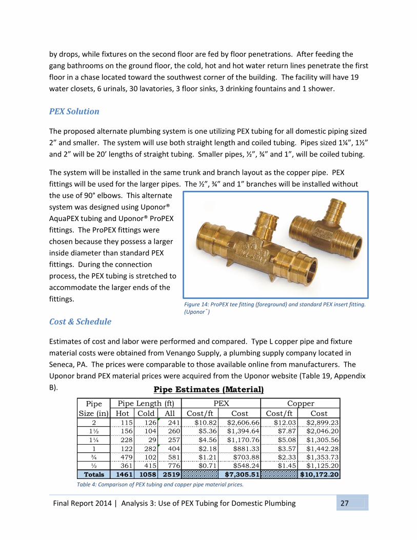
PEX Solution
The proposed alternate plumbing system is one utilizing PEX tubing for all domestic piping sized
2” and smaller. The system will use both straight length and coiled tubing. Pipes sized 1¼”, 1½”
and 2” will be 20’ lengths of straight tubing. Smaller pipes, ½”, ¾” and 1”, will be coiled tubing.
The system will be installed in the same trunk and branch layout as the copper pipe. PEX
fittings will be used for the larger pipes. The ½”, ¾” and 1” branches will be installed without
the use of 90° elbows. This alternate
system was designed using Uponor®
AquaPEX tubing and Uponor® ProPEX
fittings. The ProPEX fittings were
chosen because they possess a larger
inside diameter than standard PEX
fittings. During the connection
process, the PEX tubing is stretched to
accommodate the larger ends of the
fittings.
Cost & Schedule
Estimates of cost and labor were performed and compared. Type L copper pipe and fixture
material costs were obtained from Venango Supply, a plumbing supply company located in
Seneca, PA. The prices were comparable to those available online from manufacturers. The
Uponor brand PEX material prices were acquired from the Uponor website (Table 19, Appendix
B).
Figure 14: ProPEX tee fitting (foreground) and standard PEX insert fitting. (Uponor®)
Table 4: Comparison of PEX tubing and copper pipe material prices.
Pipe
Size (in) Hot Cold All Cost/ft Cost Cost/ft Cost2 115 126 241 $10.82 $2,606.66 $12.03 $2,899.23
1½ 156 104 260 $5.36 $1,394.64 $7.87 $2,046.20
1¼ 228 29 257 $4.56 $1,170.76 $5.08 $1,305.56
1 122 282 404 $2.18 $881.33 $3.57 $1,442.28
¾ 479 102 581 $1.21 $703.88 $2.33 $1,353.73
½ 361 415 776 $0.71 $548.24 $1.45 $1,125.20
Totals 1461 1058 2519 $7,305.51 $10,172.20
PEX CopperPipe Length (ft)
Pipe Estimates (Material)

Final Report 2014 | Analysis 3: Use of PEX Tubing for Domestic Plumbing 28
The price of ProPEX fittings is considerably higher than that of the corresponding copper fitting.
However, the ability to install the ½”, ¾” and 1” PEX tubing without the need for elbows to
change direction eliminates 428 fittings. Pricing for PEX fittings is available in Tables 20 and 21,
Appendix B.
Table 5: Comparison of PEX and copper 90 degree elbows material prices.
Table 6: Comparison of PEX and copper Tee fixture material prices.
The material and labor costs are combined for the pipe insulation. Published information was
not readily available. A combined price of $5.00 per foot was quoted by both Dalton Deeter,
Roy C. Deeter Plumbing and Heating, Cochranton, PA and Gregory Costa, McKamish, Inc.,
Pittsburgh, PA. This price was the same for both PEX and copper pipe systems. However,
because of the increased R-Value of PEX, insulation is not required on cold water lines to
prevent condensation.
Table 7: Comparison of pipe insulation material and labor costs.
Pipe
Size (in) Cost/Unit Cost Cost/Unit Cost2 14 $68.70 $961.80 $17.96 $251.44
1½ 10 $16.65 $166.50 $9.86 $98.60
1¼ 13 $12.50 $162.50 $5.75 $74.75
1 52 $5.05 $3.86 $200.72
¾ 100 $2.45 $1.57 $157.00
½ 276 $1.95 $0.70 $193.20
Totals $1,290.80 $975.71
QtyPEX Copper
90º Elbow Fitting Estimate (Material)
Pipe
Size (in) Cost/Unit Cost Cost/Unit Cost2 7 $84.60 $592.20 $31.74 $222.18
1½ 7 $19.90 $139.30 $20.36 $142.52
1¼ 13 $14.25 $185.25 $12.07 $156.91
1 11 $5.70 $62.70 $8.92 $98.12
¾ 13 $3.15 $40.95 $2.87 $37.31
½ 6 $1.95 $11.70 $1.19 $7.14
Totals $1,032.10 $664.18
Tee Fitting Estimate (Material)
QtyPEX Copper
Cost/ft Cost Cost/ft CostHot 1461 $5.00 $7,305.00 $5.00 $7,305.00
Cold 1058 $0.00 $0.00 $5.00 $5,290.00
Totals $7,305.00 $12,595.00
Pipe Insulation (Material + Labor)
L (ft)PEX Copper
Type

Final Report 2014 | Analysis 3: Use of PEX Tubing for Domestic Plumbing 29
Labor rates for the installation of PEX tubing and copper pipe were obtained from the
Mechanical Contractors Association of America’s (MCAA) Web-Based Labor Estimating Manual
(WebLEM). (Tables 22 and 23, Appendix B)
Table 8: Comparison of PEX tubing and copper pipe labor prices.
The labor information for PEX and copper fittings was also acquired from MCAA’s WebLEM.
(Tables 24 and 25, Appendix B)
Table 9: Comparison of PEX and copper 90 degree elbow labor prices.
Table 10: Comparison of PEX and copper Tee fittings labor prices.
Pipe
Size (in) Hot Cold All Hours/ft Hours Hours/ft Hours2 115 126 241 0.05 12.05 0.09 21.69
1½ 156 104 260 0.05 13.00 0.08 20.80
1¼ 228 29 257 0.05 12.85 0.08 20.56
1 122 282 404 0.05 20.20 0.07 28.28
¾ 479 102 581 0.05 29.05 0.06 34.86
½ 361 415 776 0.05 38.80 0.06 46.56
Totals 1461 1058 2519 125.95 172.75
$9,352.69Cost (based of Federal
prevailing wage rates of $54.14/hr.)$6,818.93
Pipe Estimates (Labor)
Pipe Length (ft) PEX Copper
Pipe
Size (in) Hrs./Unit Hours Hrs./Unit Hours2 14 0.25 3.50 0.85 11.90
1½ 10 0.20 2.00 0.74 7.40
1¼ 13 0.17 2.21 0.70 9.10
1 52 0.00 0.63 32.76
¾ 100 0.00 0.53 53.00
½ 276 0.00 0.40 110.40
Totals 7.71 224.56
$417.50 $12,157.68Cost ($54.14/hr.)
90º Elbow Fitting Estimate (Labor)
QtyPEX Copper
Pipe
Size (in) Hrs./Unit Hour Hrs./Unit Hour2 7 0.35 2.45 1.26 8.82
1½ 7 0.27 1.89 1.09 7.63
1¼ 13 0.23 2.99 1.03 13.39
1 11 0.19 2.09 0.92 10.12
¾ 13 0.15 1.95 0.77 10.01
½ 6 0.12 0.72 0.57 3.42
Totals 12.09 53.39
$654.55 $2,890.53Cost ($54.14/hr.)
Tee Fitting Estimate (Labor)
QtyPEX Copper

Final Report 2014 | Analysis 3: Use of PEX Tubing for Domestic Plumbing 30
The comparison of the total costs for the PEX and copper systems shows a cost savings of
$38,941.08 for the PEX alternative. This is a savings of 50%. In addition to a lower total cost,
the PEX system also saves 305 man-hours of installation time.
Advantages and Disadvantages
The previous section highlighted two of the more advantageous benefits of PEX systems. A 50%
monetary savings and 67% savings in installation time will benefit any project. These, however
are not the only advantages to PEX.
Another benefit to this system is the alleviation of open flames in plumbing installations. The
soldering of copper joints requires the use of a propane torch. The ProPEX fixtures are pressure
fit and only require an expander tool to prepare the tubing to receive the fitting. This type of
joint also mitigates the opportunity of “dry fit” joints, an issue created when a copper joint is fit
together but mistakenly not soldered together.
Due to the fewer number of fittings required, PEX systems are less likely to leak. Fittings are a
likely point of failure in any plumbing system, therefore, fewer fittings equates to fewer
opportunities for leaks. Instances of leaks are also lessened by PEX’s ability to expand, resulting
in less chance of rupture from freezing than with rigid copper pipe.
Additionally, the material itself has multiple advantages. Polyethylene is resistant to corrosion
and is not affected by acidic water, resulting in no buildup of scale and other flow reducing
debris and no metallic taste to the water. The material also is less likely than copper pipe to
transmit sounds associated with the flow of water.
The PEX product is not without deficits, however. Installing PEX fittings requires equipment
that contractors need to rent or purchase. This equipment carries with it a learning curve.
Employees will need to be trained and productivity will not be maximized until they are
comfortable with the new process.
Materials Labor Mat.+Labor Materials Labor Mat.+LaborPipe $7,305.51 $6,818.93 $14,124.44 $10,172.20 $9,352.69 $19,524.89
90º $1,290.80 $417.50 $1,708.30 $975.71 $12,157.68 $13,133.39
Tee $1,032.10 $654.55 $15,832.74 $664.18 $2,890.53 $32,658.28
Insulation $7,305.00 $12,595.00
Totals $38,970.48 $77,911.56
Total Costs
$7,305.00 $12,595.00
PEX CopperCategory
Table 11: Comparison of total costs of installation for PEX and copper systems.
Final Report 2014 | Analysis 3: Use of PEX Tubing for Domestic Plumbing 31
PEX has been in production for more than 30 years and has proved durable for at least that
length of time. Copper, however, has a longer history and in some installations is found to be
more than 100 years old. There is no way of knowing if PEX will share that longevity.
The copper material carries with it several benefits that PEX does not. Copper pipe is
bacteriostatic, which means it is resistant to the growth of bacteria. Copper pipe will not burn
in the case of a fire and it is UV resistant, allowing it to be used in exterior situations. PEX does
not share any of those characteristics.
Plumbing Breadth
Introduction
To compare the Type L copper pipe system to the alternate PEX/ProPEX system, the friction loss
was calculated for each. The fixture most distant from the domestic water supply was chosen.
This fixture was a lavatory on the first floor and was located at the end of the hot water supply
loop. Each system contained ½”, ¾”, 1”, 1¼”, 1½” and 2” pipe as well as 90 degree elbows and
Tees (Figure 18, Appendix B).
A design velocity of 4ft/s was chosen for use throughout the system. This velocity was chosen
in order to reduce the likelihood of noise caused by flowing water.
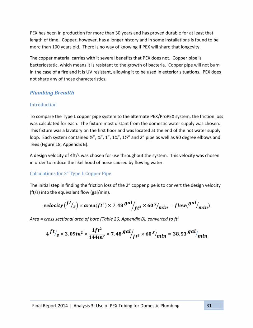
Calculations for 2” Type L Copper Pipe
The initial step in finding the friction loss of the 2” copper pipe is to convert the design velocity
(ft/s) into the equivalent flow (gal/min).
𝒗𝒆𝒍𝒐𝒄𝒊𝒕𝒚 (𝒇𝒕
𝒔⁄ ) × 𝒂𝒓𝒆𝒂(𝒇𝒕𝟐) × 𝟕. 𝟒𝟖𝒈𝒂𝒍
𝒇𝒕𝟑⁄ × 𝟔𝟎 𝒔𝒎𝒊𝒏⁄ = 𝒇𝒍𝒐𝒘(
𝒈𝒂𝒍𝒎𝒊𝒏⁄ )
Area = cross sectional area of bore (Table 26, Appendix B), converted to ft2
𝟒𝒇𝒕
𝒔⁄ × 𝟑. 𝟎𝟗𝒊𝒏𝟐 ×𝟏𝒇𝒕𝟐
𝟏𝟒𝟒𝒊𝒏𝟐× 𝟕. 𝟒𝟖
𝒈𝒂𝒍𝒇𝒕𝟑⁄ × 𝟔𝟎 𝒔
𝒎𝒊𝒏⁄ = 𝟑𝟖. 𝟓𝟑𝒈𝒂𝒍
𝒎𝒊𝒏⁄

Final Report 2014 | Analysis 3: Use of PEX Tubing for Domestic Plumbing 32
Once the flow is found, the friction loss can be calculated using the Hazen-Williams formula.
𝑷 =𝟒.𝟓𝟐×𝑸𝟏.𝟖𝟓
𝑪𝟏.𝟖𝟓×𝒅𝟒.𝟖𝟕 (Hazen-Williams formula)
P = friction loss (psi/ft)
Q = flow (gal/min)
d = average inside diameter (in) (Table 26, Appendix B)
C = Hazen-Williams Coefficient (typical design value for copper = 130) (Table 27, Appendix B)
𝑷 =𝟒. 𝟓𝟐 × 𝟑𝟖. 𝟓𝟑𝟏.𝟖𝟓
𝟏𝟑𝟎𝟏.𝟖𝟓 × 𝟏. 𝟗𝟖𝟓𝟒.𝟖𝟕= 𝟎. 𝟎𝟏𝟔𝟗
𝒑𝒔𝒊𝒇𝒕⁄
The final step is to determine the length of 2” pipe and the equivalent lengths for the fittings
(Table 28, Appendix B). The total equivalent length is then multiplied by the friction loss to find
the total friction loss for that section of the system (Table 12).
Table 12: Portion of Table 33, Appendix B for 2" copper pipe.
The same process was completed for ½”, ¾”, 1”, 1¼” and 1½” Type L copper pipe using a
spreadsheet (Table 33, Appendix B). This spreadsheet also calculated the total friction loss for
the most distant fixture.
A spreadsheet was also used to calculate the total friction loss for the same fixture using PEX
tubing and ProPEX fittings (Table 34, Appendix B). Tables 29-32, Appendix B were used to find
the friction loss and equivalent lengths for the tubing and fittings respectively.
The total friction loss calculated for each material did not include head loss due to elevation
change, as the intent was to compare the effects of one material to the other and the elevation
change is the same for both. Additionally, the friction loss for elements of the system located
before the occurrence of 2” pipe were not considered, as again, the intent was to compare the
copper and PEX systems and no PEX was used for pipe sizes larger than 2”.
The total friction loss for the copper pipe system was 23.24 psi. The total friction loss for the
PEX system was 24.45 psi. This equates to an increase of 1.21 psi when using PEX instead of
Type L copper pipe.
Pipe
Size
(in)
Velocity
(ft/s)
Flow
(gal/min)
Friction
Loss
(psi/ft)
System
Components
Equivalent
Length of
Component
Number of
Components
Total
Equivalent
Length (ft)
Total
Friction
Loss (psi)
Straight Pipe 89.00 1 89.00
90º Elbow 5.50 5 27.50
Tee 0.50 1 0.50
4.00 38.53 0.0169 117.00 1.9769
2

Final Report 2014 | Analysis 3: Use of PEX Tubing for Domestic Plumbing 33
PEX Tubing Conclusion
For years, PEX tubing has been replacing copper pipe in residential construction. However, it
has not been as widely in the commercial market. The benefits that endear PEX to residential
installers are the lower material costs and shorter installation times. Additionally, since PEX
requires fewer fittings, there are not as many opportunities for system failures. These qualities
should be just as advantageous to commercial construction.
For this elementary school, the plumbing system was designed using Type L copper pipe. An
alternate PEX system was proposed in order to compare the two. The PEX system used the
same sized pipe as the copper system, with the largest available size being 2”. Everything larger
than 2” remained copper. The alternate system also followed the same trunk and branch
design as the copper. The only main difference came in the elimination of 90 degree fittings for
the ½”, 3/4” and 1” PEX tubing. These sized pipes do not require fittings for direction changes.
After estimating the labor and material costs for the two systems, it was apparent that there
was a definite advantage to the alternate system. The material required for the PEX system
took 305 fewer hours to install than the copper system. It also saved $38,941. Those are 67%
and 50% reductions, respectively.
The remaining concern was whether the smaller inside diameter of the PEX and its fittings
cause an appreciable reduction in water pressure when compared to the copper pipe and
fittings. To calculate the friction loss of the two systems, the furthest most fixture was chosen.
Over the course of more than 650 feet of pipe, the PEX had a greater friction loss by 1.2108 psi.
Considering the impressive cost savings and the minimal decrease in pressure, the PEX system
appears to be a viable alternative for this elementary school construction project.

Final Report 2014 | Conclusion 34
Conclusion
The elementary school construction project chosen for the basis of this thesis combines the
renovation of a 140 year old, 28,000 ft2 building with the addition of 18,000 ft2 of modern
facilities. The analyses completed as part of this assignment are studies of alternate services or
systems that provide some advantages. They are not meant to be a critique of the current
design or process. Thank you to everyone who had a hand in the completion of this report.
Analysis 1: Use of Multivista® Construction Documentation
A relatively new service, third-party photo documentation provides the project owner with
reliable and detailed images of the project. Offering milestone photo shoots and progression
photos, the web-based software included with the service allows for simple access to the
product from multiple locations. Once the project is completed, the pictures serve as an exact
representation of building and its systems that maintenance and facility workers can use to
increase their productivity. The reasonable pricing structure makes this service something that
should be considered for every construction project.
Analysis 2: Use of Steel Deck and Cast-in-Place Concrete
The precast concrete plank flooring system designed for this building had the potential to delay
the schedule and did not provide for the most accommodating solution to the “Connector”
portion of the building. A steel deck/cast-in-place concrete solution provides for an easier
installation as it is not as constrained by limited access, can be adjusted onsite to fit difficult
areas and prepared in the field to accommodate last minute changes and MEP installations.
This alternate solution increases the schedule by just one day and the total construction cost by
less than 0.2%; both reasonable expenses when weighed against the benefits.
Analysis 3: Use of PEX tubing for Domestic Water
The domestic water system for this school was designed using copper with soldered joints.
While copper is the industry standard, a PEX system delivers cost and schedule reductions
without major deficit. Using the same sized pipe and “trunk and branch” installation, the PEX
system reduces costs by 50%, labor by 67% and contributes the other benefits associated with
PEX. With only a minimal reduction in water pressure, this alternative to the copper system will
benefit the project in many ways.

Final Report 2014 | Appendix A: 35
Appendix A: Use of Steel Deck and Cast-In-Place Concrete

Final Report 2014 | Appendix A: 36
Table 13: Description of crews as defined by R.S. Means.

Final Report 2014 | Appendix A: 37
Table 14: Steel deck and concrete slab information from Vulcraft Steel Roof and Floor Deck catalog.

Final Report 2014 | Appendix A: 38
Table 15: Concrete slab information from Vulcraft Steel Roof and Floor Deck catalog.

Final Report 2014 | Appendix A: 39
Table 16: Applicable portion of Table 4-1 of ASCE 7-10

Final Report 2014 | Appendix A: 40
Table 17: Pour stop selection table.

Final Report 2014 | Appendix A: 41
Figure 15: Drawing of beam locations and sizes.

Final Report 2014 | Appendix A: 42
Figure 16: Enlarged portion of Figure 15.
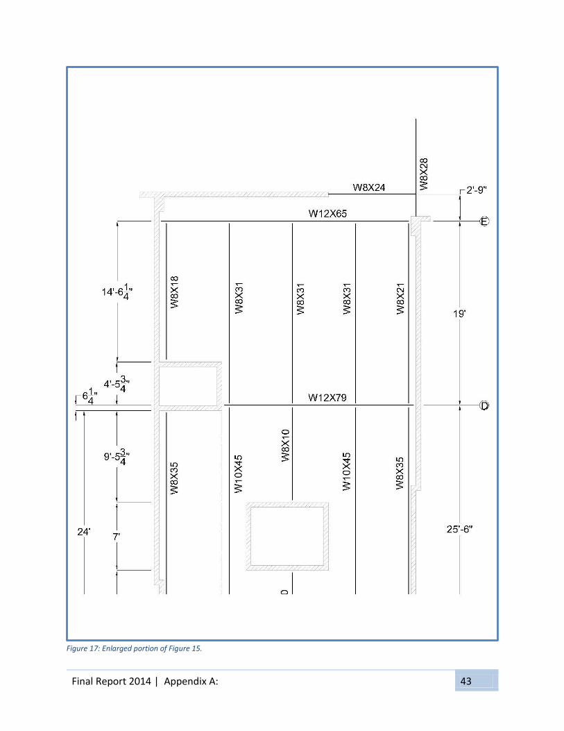
Final Report 2014 | Appendix A: 43
Figure 17: Enlarged portion of Figure 15.

Final Report 2014 | Appendix A: 44
Table 18: Steel Beam Calculation Spreadsheet
Tributary Beam Live WD WL MD ML MU VD VL VU Dallow I Beam
Width (ft) Length (ft) Deck Joists Load (psf) (lb/ft) (lb/ft) (k·ft) (k·ft) (k·ft) (kips) (kips) (kips) (in.) (in.4) Wt. (lb.)
AB 1 3.25 17.0 45.0 100.0 146.25 325.00 5.28 11.74 25.12 1.24 2.76 5.91 0.57 37.17 w8x 18 306.00
AB 2 6.50 17.0 45.0 100.0 292.50 650.00 10.57 23.48 50.25 2.49 5.53 11.82 0.57 74.33 w8x 24 408.00
AB 3 6.50 17.0 45.0 100.0 292.50 650.00 10.57 23.48 50.25 2.49 5.53 11.82 0.57 74.33 w8x 24 408.00
AB 4 6.48 17.0 45.0 100.0 291.56 647.92 10.53 23.41 50.09 2.48 5.51 11.79 0.57 74.09 w8x 24 408.00
AB 5 3.23 17.0 45.0 100.0 145.31 322.92 5.25 11.67 24.96 1.24 2.74 5.87 0.57 36.93 w8x 18 306.00
BC 1 3.25 12.5 45.0 100.0 146.25 325.00 2.86 6.35 13.58 0.91 2.03 4.35 0.42 14.77 w8x 13 162.50
BC 2 6.50 12.5 45.0 100.0 292.50 650.00 5.71 12.70 27.17 1.83 4.06 8.69 0.42 29.55 w8x 18 225.00
BC 3 6.50 15.0 45.0 100.0 292.50 650.00 8.23 18.28 39.12 2.19 4.88 10.43 0.50 51.06 w8x 18 270.00
BC 4 6.00 15.0 45.0 100.0 270.00 600.00 7.59 16.88 36.11 2.03 4.50 9.63 0.50 47.13 w8x 18 270.00
BC 5 2.75 15.0 45.0 100.0 123.75 275.00 3.48 7.73 16.55 0.93 2.06 4.41 0.50 21.60 w8x 13 195.00
CD 1 3.75 24.0 45.0 100.0 168.75 375.00 12.15 27.00 57.78 2.03 4.50 9.63 0.80 120.66 w8x 35 840.00
CD 2 6.50 24.5 45.0 100.0 292.50 650.00 21.95 48.77 104.37 3.58 7.96 17.04 0.82 222.49 w10x 45 1102.50
CD 3.1 6.50 7.5 45.0 100.0 292.50 650.00 2.06 4.57 9.78 1.10 2.44 5.22 0.25 6.38 w8x 10 75.00
CD 3.2 6.50 9.6 45.0 100.0 292.50 650.00 3.37 7.49 16.02 1.40 3.12 6.68 0.32 13.39 w8x 10 96.00
CD 4 6.00 25.5 45.0 100.0 270.00 600.00 21.95 48.77 104.37 3.44 7.65 16.37 0.85 231.57 w10x 45 1147.50
CD 5 3.25 25.5 45.0 100.0 146.25 325.00 11.89 26.42 56.53 1.86 4.14 8.87 0.85 125.43 w8x 35 892.50
DE 1 3.75 14.6 45.0 100.0 168.75 375.00 4.50 9.99 21.38 1.23 2.74 5.86 0.49 27.16 w8x 18 262.80
DE 2 6.50 19.0 45.0 100.0 292.50 650.00 13.20 29.33 62.77 2.78 6.18 13.21 0.63 103.77 w8x 31 589.00
DE 3 6.50 19.0 45.0 100.0 292.50 650.00 13.20 29.33 62.77 2.78 6.18 13.21 0.63 103.77 w8x 31 589.00
DE 4 6.00 19.0 45.0 100.0 270.00 600.00 12.18 27.08 57.94 2.57 5.70 12.20 0.63 95.79 w8x 31 589.00
DE 5 3.25 19.0 45.0 100.0 146.25 325.00 6.60 14.67 31.38 1.39 3.09 6.61 0.63 51.89 w8x 21 399.00
A 18 8.50 26.0 45.0 4.2 100.0 417.78 850.00 35.19 71.59 156.78 5.42 11.03 24.16 0.87 346.06 w12x 50 1297.92
B 17 16.00 25.0 45.0 7.3 100.0 836.96 1600.00 65.39 125.00 278.47 10.46 20.00 44.55 0.83 581.90 w12x 79 1975.00
C 47 20.25 18.5 45.0 7.1 100.0 1055.63 2025.00 44.96 86.24 191.94 9.74 18.69 41.59 0.62 296.42 w12x 58 1070.58
D 37 22.25 20.2 45.0 12.1 100.0 1270.48 2225.00 64.85 113.58 259.55 12.84 22.48 51.38 0.67 427.39 w12x 79 1596.46
E 18 10.88 26.5 45.0 5.8 100.0 552.67 1087.50 48.51 95.46 210.96 7.32 14.41 31.84 0.88 471.06 w12x 65 1722.50
denotes beams whose size is controlled by IX.
Beam
Shape
Steel Beam Calculation Spreadsheet
Beam
Jois
tsG
irders
Dead Load (psf)
Final Report 2014 | Appendix B: 45
Appendix B: Use of PEX Tubing for Domestic Plumbing

Final Report 2014 | Appendix B: 46
Table 19: PEX tubing price list - 4/9/14 (Uponor)

Final Report 2014 | Appendix B: 47
Table 20: PEX 90 degree elbow price list - 4/9/14 (Uponor)

Final Report 2014 | Appendix B: 48
Table 21: PEX Tee fitting price list - 4/9/14 (Uponor)

Final Report 2014 | Appendix B: 49
Table 22: PEX installation labor rates. (MCAA)
Table 23: Copper pipe installation labor rates. (MCAA)
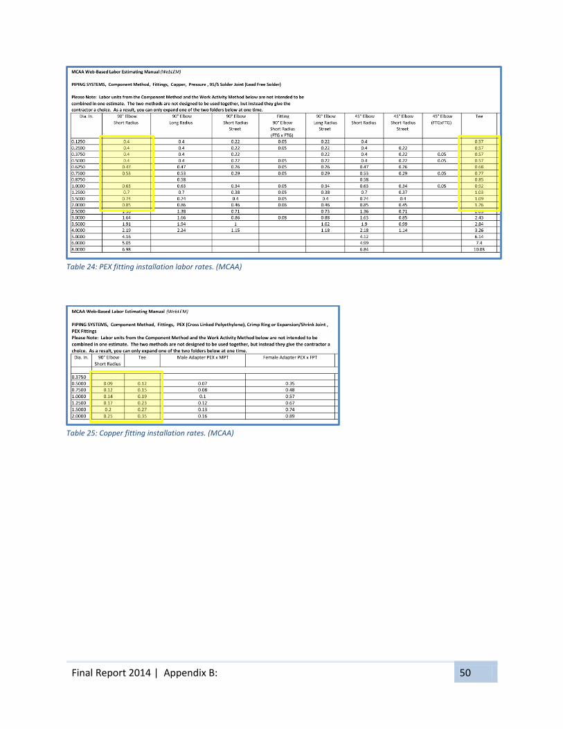
Final Report 2014 | Appendix B: 50
Table 24: PEX fitting installation labor rates. (MCAA)
Table 25: Copper fitting installation rates. (MCAA)
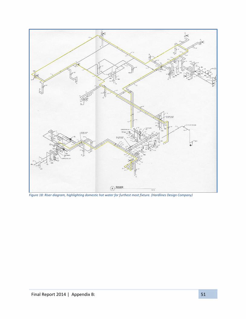
Final Report 2014 | Appendix B: 51
Figure 18: Riser diagram, highlighting domestic hot water for furthest most fixture. (Hardlines Design Company)
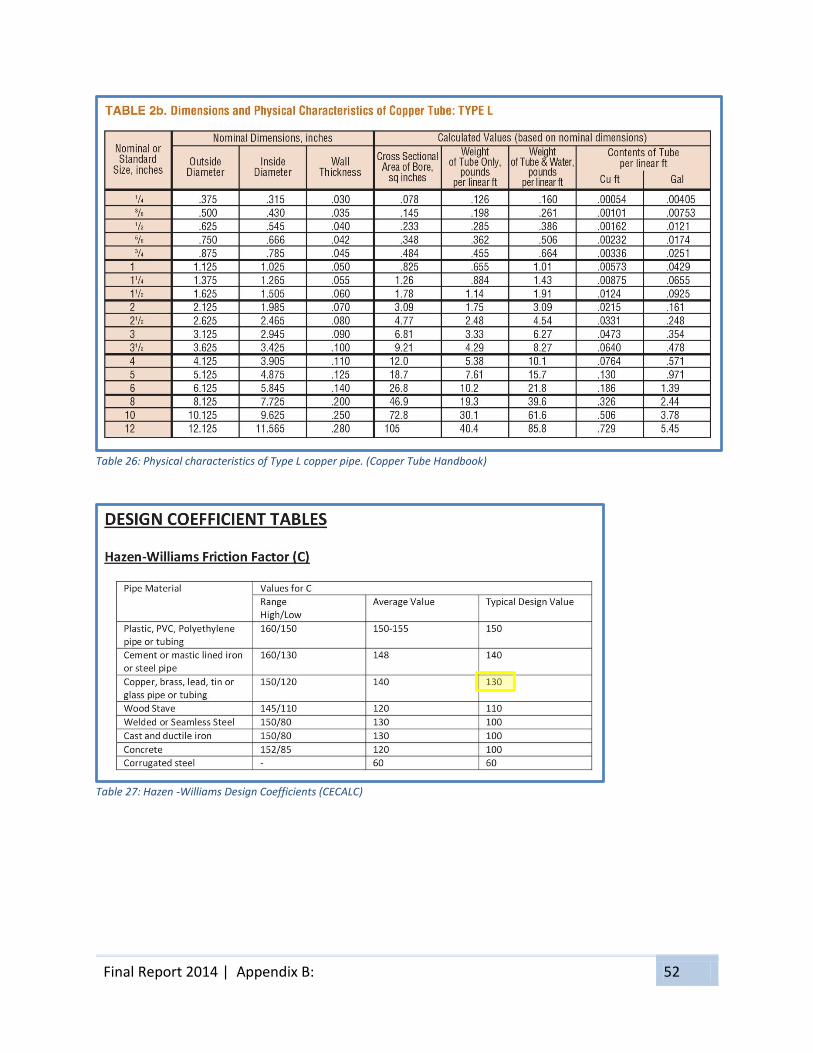
Final Report 2014 | Appendix B: 52
Table 26: Physical characteristics of Type L copper pipe. (Copper Tube Handbook)
Table 27: Hazen -Williams Design Coefficients (CECALC)

Final Report 2014 | Appendix B: 53
Table 28: Equivalent Length of copper fittings. (Copper Tube Handbook)

Final Report 2014 | Appendix B: 54
Table 29: 1/2" and 3/4" AquaPEX tubing friction loss. (Uponor)

Final Report 2014 | Appendix B: 55
Table 30: 1" and 1-1/4" AquaPEX tubing friction loss. (Uponor)

Final Report 2014 | Appendix B: 56
Table 31: 1-1/2" and 2" AquaPEX tubing friction loss. (Uponor)

Final Report 2014 | Appendix B: 57
Table 32: ProPEX Fittings Equivalent Lengths (Uponor)

Final Report 2014 | Appendix B: 58
Table 33: Total friction loss in copper pipe to most distant fixture.
Table 34: Total friction loss in PEX tubing to most distant fixture.
Pipe
Size
(in)
Velocity
(ft/s)
Flow
(gal/min)
Friction
Loss
(psi/ft)
System
Components
Equivalent
Length of
Component
Number of
Components
Total
Equivalent
Length (ft)
Total
Friction
Loss (psi)
Straight Pipe 89.00 1 89.00
90º Elbow 5.50 5 27.50
Tee 0.50 1 0.50
4.00 38.53 0.0169 117.00 1.9769
Straight Pipe 321.00 1 321.00
90º Elbow 4.00 8 32.00
Tee 0.50 7 3.50
4.00 22.19 0.0235 356.50 8.3599
Straight Pipe 80.00 1 80.00
90º Elbow 3.00 2 6.00
Tee (Branch) 0.50 1 0.50
4.00 15.71 0.0288 86.50 2.4946
Straight Pipe 103.00 1 103.00
90º Elbow 2.50 4 10.00
Tee (Branch) 4.50 5 22.50
4.00 10.29 0.0367 135.50 4.9729
Straight Pipe 64.00 1 64.00
90º Elbow 2.00 0.00
Tee 3.00 1 3.00
4.00 6.03 0.0502 67.00 3.3613
Straight Pipe 15.00 1 15.00
90º Elbow 1.00 8 8.00
Tee 2.00 2 4.00
4.00 2.90 0.0767 27.00 2.0711
23.2366Total Friction Loss to Most Distant Fixture
Friction Loss to Most Distant Fixture (Copper)
½
2
1½
1¼
1
¾
Pipe
Size
(in)
Velocity
(ft/s)
Flow
(gal/min)
Friction
Loss
(psi/ft)
System
Components
Equivalent
Length of
Component
Number of
Components
Total
Equivalent
Length (ft)
Total
Friction
Loss (psi)
Straight Pipe 89.00 1 89.00
90º Elbow 11.29 5 56.45
Tee (Branch) 1.56 1 1.56
4.00 25.99 0.0170 147.01 2.4992
Straight Pipe 321.00 1 321.00
90º Elbow 10.85 8 86.80
Tee (Branch) 2.07 7 14.49
4.00 15.16 0.0237 422.29 10.0083
Straight Pipe 80.00 1 80.00
90º Elbow 9.61 2 19.22
Tee (Thru) 1.64 1 1.64
4.00 10.88 0.0290 100.86 2.9249
Straight Pipe 103.00 1 103.00
90º Elbow 3.40 0 0.00
Tee (Thru) 2.00 5 10.00
4.00 7.28 0.0373 113.00 4.2149
Straight Pipe 64.00 1 64.00
90º Elbow 2.20 0 0.00
Tee (Thru) 0.80 1 0.80
4.00 4.41 0.0510 64.80 3.3048
Straight Pipe 15.00 1 15.00
90º Elbow 3.00 0 0.00
Tee (Branch) 2.00 2 4.00
4.00 2.21 0.0787 19.00 1.4953
24.4474Total Friction Loss to Most Distant Fixture
Friction Loss to Most Distant Fixture (PEX)
2
1½
1¼
1
¾
½

Final Report 2014 | Appendix C: 59
Appendix C: Table and Figure Index

Final Report 2014 | Appendix C: 60
Table Index
Table 1: Cost comparison for ADA handrail repairs...................................................................... 12
Table 2: Cost comparison for window repairs. ............................................................................. 14
Table 3: Cost and duration estimate for first floor (second floor values are the same). ............. 22
Table 4: Comparison of PEX tubing and copper pipe material prices. ......................................... 27
Table 5: Comparison of PEX and copper 90 degree elbows material prices. ............................... 28
Table 6: Comparison of PEX and copper Tee fixture material prices. .......................................... 28
Table 7: Comparison of pipe insulation material and labor costs. ............................................... 28
Table 8: Comparison of PEX tubing and copper pipe labor prices. .............................................. 29
Table 9: Comparison of PEX and copper 90 degree elbow labor prices. ...................................... 29
Table 10: Comparison of PEX and copper Tee fittings labor prices. ............................................. 29
Table 11: Comparison of total costs of installation for PEX and copper systems. ....................... 30
Table 12: Portion of Table 32, Appendix B for 2" copper pipe. .................................................... 32
Table 13: Description of crews as defined by R.S. Means. ........................................................... 36
Table 14: Steel deck and concrete slab information from Vulcraft Steel Roof and Floor Deck
catalog. .......................................................................................................................................... 37
Table 15: Concrete slab information from Vulcraft Steel Roof and Floor Deck catalog. ............. 38
Table 16: Applicable portion of Table 4-1 of ASCE 7-10 ............................................................... 39
Table 17: Pour stop selection table. ............................................................................................. 40
Table 18: Steel Beam Calculation Spreadsheet ............................................................................ 44
Table 19: PEX tubing price list - 4/9/14 (Uponor) ......................................................................... 46
Table 20: PEX 90 degree elbow price list - 4/9/14 (Uponor) ........................................................ 47
Table 21: PEX Tee fitting price list - 4/9/14 (Uponor) ................................................................... 48
Table 22: PEX installation labor rates. (MCAA) ............................................................................. 49
Table 23: Copper pipe installation labor rates. (MCAA) ............................................................... 49
Table 24: PEX fitting installation labor rates. (MCAA) .................................................................. 50
Table 25: Copper fitting installation rates. (MCAA) ...................................................................... 50
Table 26: Physical characteristics of Type L copper pipe. (Copper Tube Handbook) ................... 52
Table 27: Hazen -Williams Design Coefficients (CECALC) ............................................................. 52
Table 28: Equivalent Length of copper fittings. (Copper Tube Handbook) .................................. 53
Table 29: 1/2" and 3/4" AquaPEX tubing friction loss. (Uponor) ................................................. 54
Table 30: 1" and 1-1/4" AquaPEX tubing friction loss. (Uponor).................................................. 55
Table 31: 1-1/2" and 2" AquaPEX tubing friction loss. (Uponor).................................................. 56
Table 32: ProPEX Fittings Equivalent Lengths (Uponor) ............................................................... 57
Table 33: Total friction loss in copper pipe to most distant fixture. ............................................ 58
Table 34: Total friction loss in PEX tubing to most distant fixture. .............................................. 58
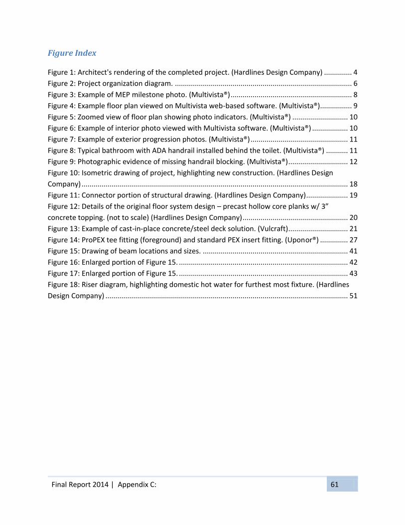
Final Report 2014 | Appendix C: 61
Figure Index
Figure 1: Architect's rendering of the completed project. (Hardlines Design Company) .............. 4
Figure 2: Project organization diagram. ......................................................................................... 6
Figure 3: Example of MEP milestone photo. (Multivista®) ............................................................. 8
Figure 4: Example floor plan viewed on Multivista web-based software. (Multivista®) ................ 9
Figure 5: Zoomed view of floor plan showing photo indicators. (Multivista®) ............................ 10
Figure 6: Example of interior photo viewed with Multivista software. (Multivista®) .................. 10
Figure 7: Example of exterior progression photos. (Multivista®) ................................................. 11
Figure 8: Typical bathroom with ADA handrail installed behind the toilet. (Multivista®) ........... 11
Figure 9: Photographic evidence of missing handrail blocking. (Multivista®) .............................. 12
Figure 10: Isometric drawing of project, highlighting new construction. (Hardlines Design
Company) ...................................................................................................................................... 18
Figure 11: Connector portion of structural drawing. (Hardlines Design Company) ..................... 19
Figure 12: Details of the original floor system design – precast hollow core planks w/ 3”
concrete topping. (not to scale) (Hardlines Design Company) ..................................................... 20
Figure 13: Example of cast-in-place concrete/steel deck solution. (Vulcraft) .............................. 21
Figure 14: ProPEX tee fitting (foreground) and standard PEX insert fitting. (Uponor®) .............. 27
Figure 15: Drawing of beam locations and sizes. ......................................................................... 41
Figure 16: Enlarged portion of Figure 15. ..................................................................................... 42
Figure 17: Enlarged portion of Figure 15. ..................................................................................... 43
Figure 18: Riser diagram, highlighting domestic hot water for furthest most fixture. (Hardlines
Design Company) .......................................................................................................................... 51

Final Report 2014 | Appendix D: 62
Appendix D: Acknowledgements

Final Report 2014 | Appendix D: 63
Robert Leicht Kevin Parfitt Moses Ling Stephen Treado
Peggy Murphy Matt Allen Joe Studer
Randy Johnson Matt Rolfe
Gary Runyan
Dalton Deeter

Final Report 2014 | Appendix D: 64
Shashi Savla
Raymond Roy
Matthew Barrett
Gregory Costa
. . . and to my family for giving me the opportunity and
encouragement to finish what I started.

Final Report 2014 | Appendix E: 65
Appendix E: References
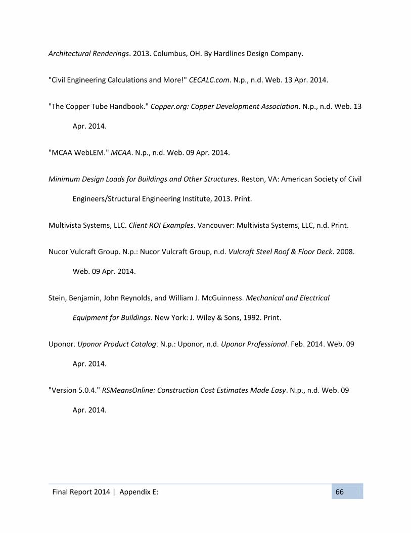
Final Report 2014 | Appendix E: 66
Architectural Renderings. 2013. Columbus, OH. By Hardlines Design Company.
"Civil Engineering Calculations and More!" CECALC.com. N.p., n.d. Web. 13 Apr. 2014.
"The Copper Tube Handbook." Copper.org: Copper Development Association. N.p., n.d. Web. 13
Apr. 2014.
"MCAA WebLEM." MCAA. N.p., n.d. Web. 09 Apr. 2014.
Minimum Design Loads for Buildings and Other Structures. Reston, VA: American Society of Civil
Engineers/Structural Engineering Institute, 2013. Print.
Multivista Systems, LLC. Client ROI Examples. Vancouver: Multivista Systems, LLC, n.d. Print.
Nucor Vulcraft Group. N.p.: Nucor Vulcraft Group, n.d. Vulcraft Steel Roof & Floor Deck. 2008.
Web. 09 Apr. 2014.
Stein, Benjamin, John Reynolds, and William J. McGuinness. Mechanical and Electrical
Equipment for Buildings. New York: J. Wiley & Sons, 1992. Print.
Uponor. Uponor Product Catalog. N.p.: Uponor, n.d. Uponor Professional. Feb. 2014. Web. 09
Apr. 2014.
"Version 5.0.4." RSMeansOnline: Construction Cost Estimates Made Easy. N.p., n.d. Web. 09
Apr. 2014.


