
Georgia DOT Research Project
Sensing System Development for HOV/HOT (High
Occupancy Vehicle) Lane Monitoring
Office of Materials and Research
Research and Development Branch


3
GDOT Research Project No. RP 07-26
Sensing System Development for HOV (High Occupancy Vehicle) Lane Monitoring
Draft Final Report
SENSING SYSTEM DEVELOPMENT FOR HOV (HIGH OCCUPANCY VEHICLE) LANE
MONITORING
By
Wayne Daley Principal Research Engineer
Omar Arif
John Stewart Jack Wood Colin Usher Erin Hanson
John Turgeson Doug Britton
Georgia Tech Research Institute
Contract with
Georgia Department of Transportation In cooperation with
U.S. Department of Transportation Federal Highway Administration
February, 2011
The contents of this report reflect the views of the author(s) who is (are) responsible for the facts and the accuracy of the data presented herein. The contents do not necessarily reflect the official views or policies of the Georgia Department of Transportation or of the Federal Highway Administration. This report does not constitute a standard, specification, or regulation.

i
ACKNOWLEDGEMENTS
We would like to acknowledge the assistance of GDOT personnel at the TMC, GDOT
Research, Randy Guenzler and Michael Hunter faculty of the school of CEE at Georgia
Tech.

ii
ABSTRACT
With continued interest in the efficient use of roadways the ability to monitor the use of
HOV/HOT lanes is essential for management, planning and operation. A system to
reliably monitor these lanes on a continuous basis and provide usage statistics would be
very helpful in supporting management operations and decision making. In this study
we evaluated the potential of an imaging system that would be installed on the median
wall of HOV/HOT lanes to acquire data on the vehicles using the lanes and the
occupancy of these vehicles. A lab prototype consisting of an IR illuminator, a camera,
vehicle trigger, a computer and software to control the system was integrated and
evaluated. Data was taken at GTRI facilities, sites on the Georgia Tech campus and also
on interstate 85. The images taken were then analyzed for their ability to provide the
information needed on the usage of the lanes. The results indicate that it would be
possible to build a system that would be able to provide the data needed to support the
operation of HOV/HOT lanes.

iii
Key words: HOV, HOV lanes, HOT lanes, traffic, vehicle occupancy, machine vision, computer vision
iv
TABLE OF CONTENTS
ACKNOWLEDGEMENTS ........................................................................................................ i
ABSTRACT .............................................................................................................................ii
TABLE OF CONTENTS........................................................................................................... iv
LIST OF FIGURES .................................................................................................................. vi
INTRODUCTION ................................................................................................................... 1
PROCEDURE ...................................................................................................................... 10
FINDINGS ........................................................................................................................... 11
SENSING ..................................................................................................................... 11
Geometry .............................................................................................................. 11
Trigger Selection ................................................................................................... 13
Imaging .................................................................................................................. 15
Window/Glass Studies ..................................................................................... 15
Camera Selection ............................................................................................. 17
Optics and Illumination .................................................................................... 19
Incident Angles ................................................................................................. 23
PROCESSING ASPECTS ................................................................................................ 26
CONTROL SYSTEM SOFTWARE .................................................................................. 28

v
IMAGE PROCESSING SOFTWARE ............................................................................... 30
SYSTEM TESTING ........................................................................................................ 31
Street Testing ........................................................................................................ 31
Interstate Testing .................................................................................................. 33
Distance and Illumination Tests ............................................................................ 34
Illumination Pattern Evaluation ....................................................................... 34
Working Distance Tests .................................................................................... 38
PROCESSING/ANALYSIS ..................................................................................................... 41
CONCEPT FOR DEMONSTRATION FIELD INSTALLATION ................................................... 44
Hardware ................................................................................................................... 45
Software ..................................................................................................................... 46
RECOMMENDATIONS ....................................................................................................... 46
REFERENCES ...................................................................................................................... 48
BIBLIOGRAPHY .................................................................................................................. 49
APPENDICES ...................................................................................................................... 50
Appendix I: Sample Output Images .......................................................................... 50
Appendix II: Software Design ..................................................................................... 52
Appendix III: Image Processing Approaches .............................................................. 63
Appendix IV: LED Evaluation ...................................................................................... 81
vi
LIST OF FIGURES
Figure 1: Passenger in Vehicle. .......................................................................................... 4
Figure 2: Extracted Passenger in Vehicle. ........................................................................... 4
Figure 3: Transmission Properties of Infrared-blocking Automobile Glass. ....................... 6
Figure 4 Overhead view of Potential site using Google Sketch Up ................................. 12
Figure 5 Example view angle providing view of rear seat ............................................... 12
Figure 6 Potential test site for demo system .................................................................... 13
Figure 7 Design for Glass Transmission Measurement System ........................................ 16
Figure 8 Comparison of transmission measurement apparatus with CARY
spectrophotometer ........................................................................................................... 16
Figure 9 Transmission data from samples of commercially available windshields .......... 17
Figure 10 Spectral response of the monochrome Chameleon camera ........................... 18
Figure 11 Perkin Elmer MVS 5770 IR Illuminator spectral output .................................... 20
Figure 12 Perkin Elmer MVS 5770 IR Illuminator power output vs. range ...................... 21
Figure 13 Sample Illumination LED array ........................................................................ 23
Figure 14 Test apparatus for LEDs ................................................................................... 23
Figure 15 Transmission measurements at various orientations...................................... 24
Figure 16 Effect of pitch on transmission ........................................................................ 25
Figure 17 Effect of yaw on transmission .......................................................................... 25
Figure 18 Initial System configuration IR illuminator t a laser trigger and camera. ........ 26
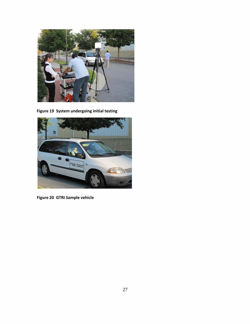
Figure 19 System undergoing initial testing .................................................................... 27

vii
Figure 20 GTRI Sample vehicle ......................................................................................... 27
Figure 21 Sample output image ....................................................................................... 28
Figure 22 second sample image ........................................................................................ 28
Figure 23 Graphical User Interface to control the system............................................... 30
Figure 24 Graphical User Interface for file viewing ......................................................... 30
Figure 25 Georgia Tech Test Site ...................................................................................... 31
Figure 26 Interstate-85 Test Site....................................................................................... 31
Figure 27 Campus Sample 1 .............................................................................................. 32
Figure 28 Campus Sample 2 .............................................................................................. 32
Figure 29 First I 85 Sample 1 ............................................................................................. 33
Figure 30 First I 85 Sample 2 ............................................................................................. 33
Figure 31 First I 85 Sample 3 ............................................................................................. 33
Figure 32 First I 85 Sample 4 ............................................................................................. 33
Figure 33 Nine feet from wall, No fresnel ........................................................................ 37
Figure 34 – Nine feet from wall, Fresnel with grooves out (the prescribed usage
orientation) ....................................................................................................................... 37
Figure 35 – Nine feet from wall, Fresnel with grooves in ................................................. 38
Figure 36 Reflected Energy at Different Distances ........................................................... 39
Figure 37 Falloff in reflected energy intensity vs. distance ............................................. 40
Figure 38 Second I 85 Sample 1 ........................................................................................ 41
Figure 39 Second I 85 Sample 2 ........................................................................................ 41
viii
Figure 40 Sample processed output green region window red region people ............... 44
Figure 41 Concept for demo system implementation ..................................................... 46
Figure 42 - Software Design Block Diagram ...................................................................... 56
Figure 43 - DoProcess Function Flowchart ....................................................................... 59
Figure 44 - Program Dialog with Camera Option .............................................................. 60
Figure 45 - Program Dialog with File Loading Option ....................................................... 60
Figure 46: Example template for window detection. ....................................................... 66
Figure 53: Voltage measured across LED array when pulsed ........................................... 82
Figure 54: Measuring cone of light from LED array .......................................................... 83
Figure 55: Cropped region used for LED tests .................................................................. 83
Figure 56: Colormap of intensity values for LED array ..................................................... 85
Figure 57: Contours of colormap for LED array ................................................................ 86
Figure 58: Experiment Setup ............................................................................................ 87

ix
1
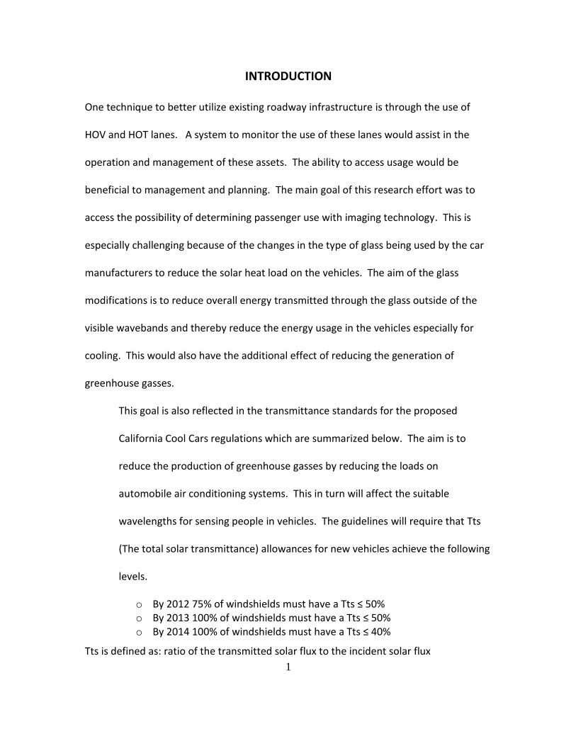
INTRODUCTION
One technique to better utilize existing roadway infrastructure is through the use of
HOV and HOT lanes. A system to monitor the use of these lanes would assist in the
operation and management of these assets. The ability to access usage would be
beneficial to management and planning. The main goal of this research effort was to
access the possibility of determining passenger use with imaging technology. This is
especially challenging because of the changes in the type of glass being used by the car
manufacturers to reduce the solar heat load on the vehicles. The aim of the glass
modifications is to reduce overall energy transmitted through the glass outside of the
visible wavebands and thereby reduce the energy usage in the vehicles especially for
cooling. This would also have the additional effect of reducing the generation of
greenhouse gasses.
This goal is also reflected in the transmittance standards for the proposed
California Cool Cars regulations which are summarized below. The aim is to
reduce the production of greenhouse gasses by reducing the loads on
automobile air conditioning systems. This in turn will affect the suitable
wavelengths for sensing people in vehicles. The guidelines will require that Tts
(The total solar transmittance) allowances for new vehicles achieve the following
levels.
o By 2012 75% of windshields must have a Tts ≤ 50% o By 2013 100% of windshields must have a Tts ≤ 50% o By 2014 100% of windshields must have a Tts ≤ 40%
Tts is defined as: ratio of the transmitted solar flux to the incident solar flux
2
Earlier attempts at using imaging utilized energy in the IR (infrared) wavelength bands.
With the proposed changes in the types of glass these systems will now be hampered in
their ability to provide the desired functionality.
The main goal of this effort is to assess the possibility for sensing in vehicles that are
using the current types of glass as well as the possibility for automated processing and
counting under these conditions.
Detecting and automatically counting vehicle occupants using a visual camera pose
numerous challenges such as reflection from the windshield, different operation
conditions, and shadows. Most of the work in this regard uses a combination of visual
and near infra-red (NIR) range. NIR is almost completely transmitted by the vehicle
windshields. Following is a brief description of the state of the art in automatic
detection of vehicle occupants.
Background
The work proposed would build on the knowledge and experience obtained from a
previous GDOT research project conducted during 1995-1998 titled “Computer Assisted
Infrared Imaging System for Determining Vehicle Occupancy” (called GVOS for Georgia
Vehicle Occupancy System). The goals of that study were twofold: the primary goal was
to develop and demonstrate new technology for planning data collection, and a
secondary goal was to determine the feasibility of the approach for HOV enforcement.
GTRI developed and demonstrated a system that accomplished the desired goals. A

3
sample image acquired at highway speed on I-285 using this first-generation system is
shown in Figure 1.
As part of the study, we also conducted a test using observers on the roadside
compared to observers using images acquired by the GVOS system. A total of 200
images were recorded in the car-by-car tests. The vehicles in this sample were carefully
selected by the observers, who believed that they had a clear view and that they could
accurately determine occupancy and seating configurations in each case. Their
observations were recorded on paper forms. The corresponding GVOS image data was
later examined in the laboratory and scored in the same manner, by two persons using
the same paper forms as the roadside observers.
Of the 200 GVOS images, 179 (90 percent) were useful and 21 were not, due to misfires.
When the 179 images were scored in the laboratory, one observer’s data agreed with
the roadside data in 95 percent of the cases, while the other observer agreed in 93
percent of the cases. The comparison also revealed another interesting fact: in four
cases (2 percent), the GVOS images clearly showed children in the back seat who were
not recorded by the roadside observers. We concluded that the GVOS system provided
the capability to accurately determine vehicle occupancy.
4
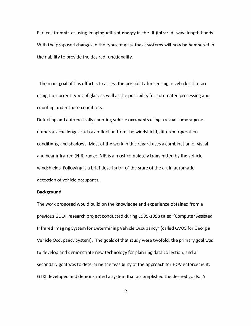
Figure 1: Passenger in Vehicle.
Figure 2: Extracted Passenger in Vehicle.
The system utilized invisible, near infrared (NIR) light (greater than 850nm wavelength)
that was provided by a Xenon strobe with a short flash duration (1/10,000 second). The
camera used was a low-light-level, intensified camera. It collected data of all of the
vehicles in the lane being monitored. For each vehicle, the system produced an infrared
(IR) flash and recorded an image with the IR camera that was digitized with a PC frame
grabber. This data was then stored for later retrieval and visual analysis. This system
demonstrated that it was possible to acquire images at 80 mph that would be suitable
for HOV occupancy determinations with human analysis. As part of this proposed
effort, we would develop a tool to automate this analysis process to reduce the
workload on the operators.

5
In addition, the technical opportunities and challenges have changed somewhat during
the past eight years, thus driving the need for a modified solution. The most significant
change is an industry trend toward a new type of automobile glass that has been
modified to reduce the transmission of IR sunlight as a means of reducing the heat load
on cars during the summer season. This means that the earlier system using an IR flash
in the 859 nm wavelength has limited practicality as that system would not see into
many vehicles that had glass with reduced IR transmission. A sample plot of the
transmission spectrum for this new glass is presented in Figure 3. It can be observed
that in the near IR (900 – 1400 nm) the transmission of ambient sunlight and the earlier
system’s IR flash strobe are significantly reduced, thereby hindering the ability to sense
energy in these wavebands in order to acquire an image.
It is proposed under this study to develop and evaluate a system that would function
close to the 700 nm limit of the visible spectrum. This will require the design of a
system that includes the sensing and illumination elements needed to acquire images at
the proposed new wavelengths.
6
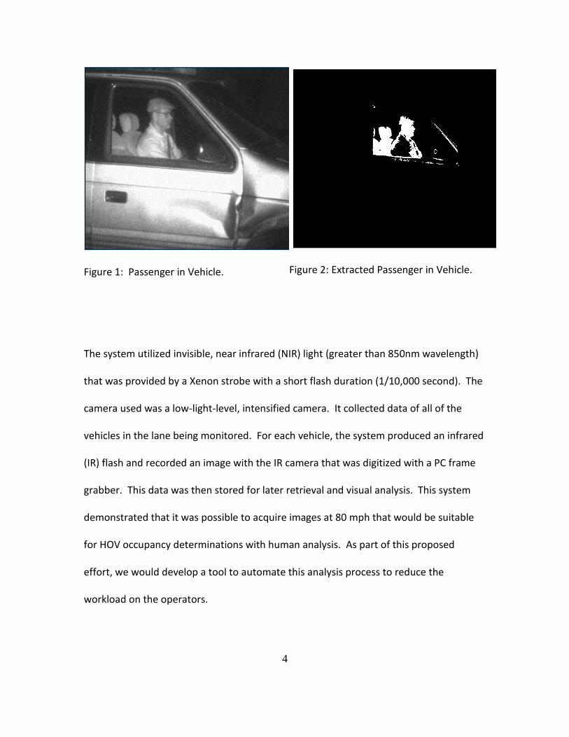
Figure 3: Transmission Properties of Infrared-blocking Automobile Glass.
A review of the technology in a study conducted by the Texas Transportation Institute
(TTI)[7] indicated that at the time of writing there was one commercial system under
development utilizing a dual band sensing approach: one in the visible and one in the
NIR. The system known as Cyclops is manufactured by Vehicle Occupancy Ltd. in
England. The study, however, indicated that the device needed improvements to be
considered sufficiently accurate and reliable based on field trials. The company’s
current website describes the system, but technical details on its operation and
performance are not known at this time.

7
The study also investigated certain within-vehicle occupancy technologies whose
primary purposes were for other reasons such as the intelligent control of seatbelts.
These technologies might potentially be used with a second purpose being occupancy
data acquisition. It has been proposed that some of these other technologies might be
utilized, but there is no current infrastructure to make this data available for monitoring
vehicle occupancy[5]. Developments underway might make this possible in the future,
but they will take years to bring into practice, require significant infrastructure
upgrades, and it would probably not be feasible to retrofit older vehicles. A system such
as the one being proposed that is capable of roadside monitoring of vehicle occupancy is
vital for providing the data needed for the proper management of HOV operations.
As part of the TTI study[7], researchers also investigated the range of technologies that
could be used for Roadside Monitoring and identified the use of near IR as one of the
more promising technologies based on somewhat generic operational specifications.
The results of the comparison from the TTI study are presented in Table 1. By this
analysis, a near IR system solution is the only one that meets the stated specifications.
This conclusion supports our proposal to build on the earlier Georgia Tech work and
develop a system to function in the near IR spectral region in the vicinity of the 700 nm
wavelength. The study will evaluate the requirement that the system will operate under
the desired environmental conditions while not being a distraction to drivers.

8
Table 1: Performance Comparison of Roadside Occupancy Detection Technologies.
Desirable Property Visible Light (Passive)
Near Infrared
Thermal Infrared
UWB Radar
Microwave
Not blocked by tinted vehicle windows
N Y N N N
Capable of all-weather and night-time operation
N Y Y Y Y
Capable of resolving vehicle cabin details
Y Y N N N
Fast enough to capture vehicles moving at freeway speeds
Y Y Y N N
Other technological advances beneficial to the study effort include: reduced cost
cameras, more controllable illumination sources, as well as the reduced cost and
improved capability of current computer systems. These developments should allow for
a more cost-effective implementation than the prototype developed in the previous
research effort. The other element of this project will be to begin development of an
image processing program to support people counting for evaluation of the system.
Preliminary work indicates that tools could be developed to support the automatic
counting of people in the vehicles as illustrated in Figure 1 and Figure 2. Figure 2 was
obtained by processing the digital image in Figure 1 to highlight the driver. Further
processing would be utilized to perform counting, for example, by looking at the shapes
and other features in the window area. It is anticipated that most of this development
would be conducted in the Phase 1 part 2 activities described below.

9
A review of current options found no system able to fully accommodate the proposed
changes. Detect provides a commercially available automated system for determining
the number of occupants within moving road vehicles
(http://www.vehicleoccupancy.com.) The system projects two low intensity beams of
Infrared (IR) light of different wavelengths onto the vehicle. Two digital photos are taken
and merged to produce a single image and then processed by software based
algorithms to detect the number of people.
Similarly in (Hao, Chen, Yao, Yang, Bi, & Wang, 2010), the authors use the near infra-red
(NIR) illuminator to illuminate the interior of the car and a digital photo is captured
using a camera equipped with an NIR filter. This setup reduces the effect of reflection of
light from the windshield of the car. The captured photo can be viewed by a human
screener or processed by computer vision algorithms to determine the number of
occupants. Other work that uses the NIR range is (Wood, Gimmestad, & Roberts, 2003).
Alternate to NIR range is to use thermal imaging systems to detect occupants using their
heat map. However the use of athermic metallic coatings on the glass prevents the
penetration of these wavelengths through the windshield. The changes being proposed
in the windshield specifications would pose operational problems for the
aforementioned systems. The main goal of this work is to develop and evaluate a
technique to allow systems to operate under these conditions and to provide the data
and information needed to support the operations on HOV/HOT systems.

10
PROCEDURE
This study will look at the two main elements of the system. These are: Sensing and
Processing. In addition there is testing of the proposed approaches and the generation
of a conceptual design of a test system that could be installed for evaluation under
operational conditions. The report will be structured as described below in the section
of titled Findings.
Sensing Aspects:
Geometry
Trigger selection
Imaging
o Window studies
o Camera selection
o Optics/Illumination
Processing Aspects:
Overall control system software
Image Processing Software
System Testing
Street Data acquisition
Highway data acquisition
Processing/Analysis
Conceptual Design System for Field Testing
Hardware
Software

11
FINDINGS
As presented earlier the work will be conducted in the areas of Sensing, Processing,
Testing and the Generation of a conceptual design. The sections that follow will address
each of these aspects.
SENSING
The work on the sensing area looked at the geometry involved in the system design. In
addition the imaging optics, of identification and selection of a trigger, camera and
processing unit are covered.
Geometry
It is required of this system that we be able to access the number of occupants in the
vehicles. We therefore had to have view angles that allowed us to see passengers as
currently the assumption could be made that there is a driver in the vehicle. In order to
meet the needs of HOT types of operation it is necessary to be able to look in the back
seats of vehicles as one HOT requirement will be that there has to be at least three
people in the vehicle. Using a utility called Google Sketch Up we were able to generate
CAD representations of the potentially different site configurations, poses and
orientations of the cameras as shown in Figure 4. This also enabled us to estimate
working distances and field of views that provided the parameters needed for our optics
calculations.
We initially considered a heads on view but changed to a more frontal/side view that
provided a view of the rear seat of the vehicle. An example is shown in Figure 5.

12
Figure 4 Overhead view of Potential site using Google Sketch Up
Figure 5 Example view angle providing view of rear seat
We visited a potential test site for a demonstration system at I-85 and Pleasant Hill road
as suggested by Mr. James Gordon with the GDOT.

13
Figure 6 Potential test site for demo system
Using data from the site visit and the Google Sketch-up we completed the specification
of the camera lens. In addition we discussed a technique for triggering the system and
settled on an IR range finder for the system trigger.
We also had an interest in the angles of incidences that would occur based on the
possible geometries and conducted tests to determine their effects.
Trigger Selection
We selected an MDL Laser Systems ILM OEM laser module for this project. It is capable
of measuring range, speed and height of vehicles. The device operates under the
principle of time-of-flight. There are two windows on the front end of the laser. One

14
window emits a short pulse of eye safe radiation and the second window, which
contains a photo detector circuit, collects the reflected light. The distance is calculated
by measuring the time it takes the light to reach back the laser module. The laser was
selected because it can work to a 1 square meter target at a distance of 150m at 200 Hz.
It was also eye safe. The selected laser is already being used in security, construction
and aviation markets. However, in practice there are several factors that define how
well the laser will work, such as the target reflectivity, size of the target and distance of
the target.
One issue that needs to be addressed is that the laser did not trigger in a timely manner
in about 10% of the vehicles. In some cases it triggered late and in some it did not
trigger at all. Mostly these were dark and shiny color vehicles. During the experiments it
was noted that if the distance between the laser and the vehicle is more than 15m, the
laser captured 100% of the vehicles. At closer distances, about 10% of the vehicles are
missed. We think it is due to the use of round (pencil) laser beam. At shorter distances
the laser beam is too focused and sometimes may hit the vehicle at an angle where all
light is scattered and nothings reflects back. This problem can be alleviated by using a
fanned laser module, which forces the beam to diverge in the vertical plane. In the
horizontal plane, the laser beam remains collimated. Figure 8 shows a picture of fanned
laser module.

15
Imaging
Window/Glass Studies
One of the motivating factors for this work is the knowledge that car makers were
moving to types of windshield and window glasses with the capability for rejecting more
of the solar load. One of the first tasks was to tests samples of current windshields to
observe their transmittance. A test apparatus was designed as shown in Figure 7. The
output from this apparatus was compared to the output from a standard lab
spectrophotometer for several samples and shown to produce representative results.
This data is presented in Figure 8 for a CARY spectrophotometer and our device. Using
our apparatus several wind shield samples were tested to obtain the transmission plots
as shown in Figure 9. We are able to see the fall off in transmission above 780 or so
nanometers in most of the models. This supported the need for an illumination system
that could penetrate the vehicle while still being unobtrusive. A system using IR as in
earlier demonstrations would not function under these conditions. A system to
penetrate the vehicle while being somewhat unobtrusive to the drivers was needed for
this problem. Our strategy is to design a system that would allow us to operate just
outside of the visible region in a ‘strobed’ mode to reduce the potential to distract the
drivers.

16
Figure 7 Design for Glass Transmission Measurement System
Figure 8 Comparison of transmission measurement apparatus with CARY spectrophotometer
0
20
40
60
80
100
500 700 900 1100
% T
ran
smis
sio
n
Wavelength (nm)
Filter Transmission
CARY
RG850
Orange Glass
800FS40
FB850
FB900
FB1000
OCEAN OPTICS
Orange Glass
17
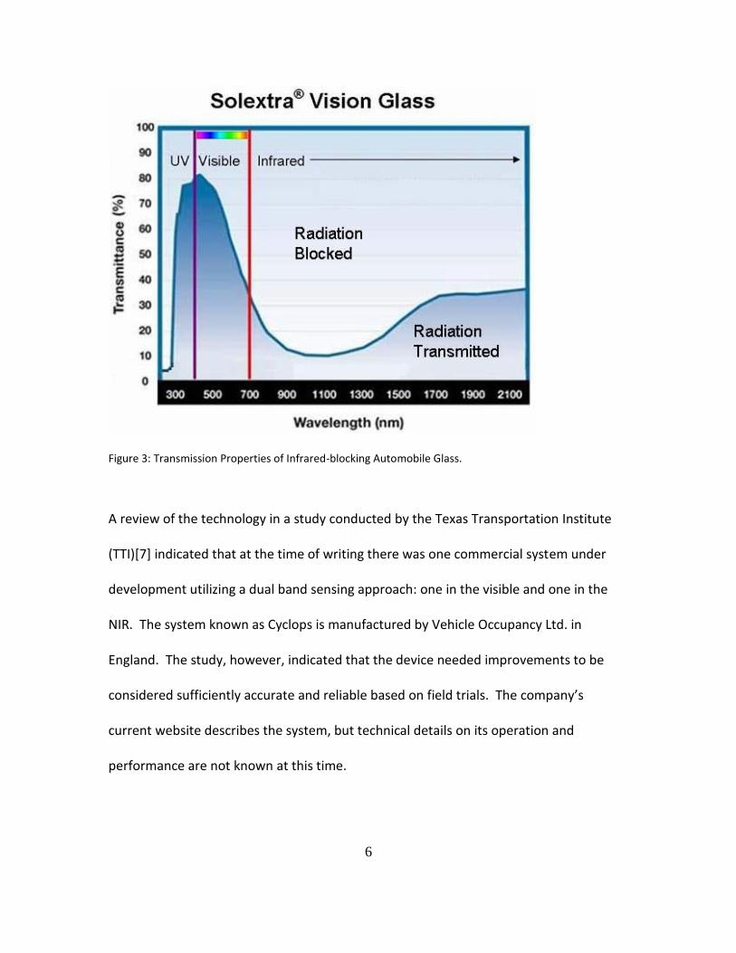
Figure 9 Transmission data from samples of commercially available windshields
We also began looking for sources of illumination that could provide energy in the
wavelength bands required to penetrate the vehicles.
Camera Selection
Based on the requirements for the sensing we chose a Point Grey monochrome
Chameleon camera with a response up to 850 nm. The general idea is that the cutoff
for the windshields would never be perfect so that there is always likely to be some
transmission in the wavelengths a little above the visible portion of the wavelength
bands. The ability to acquire data at these wavelengths would make the system
unobtrusive to the drivers. The Point Grey Research Chameleon CMLN-13S2M adheres
to the IIDC 1394-based Digital Camera Specification v1.31 but features the USB 2.0
0
10
20
30
40
50
60
70
80
90
100
400 500 600 700 800 900
Pe
rce
nt
Tran
smis
sio
n
Wavelength (nanometers)
Windshield Transmission 3/5/2010 at Glass Doctor in Norcross)
DW01255_GBYLOF
DW01231 GGNPPG
FW02009 GBNPPG
FW02012 ZTNPPG
FW02734 GBNPLK
FW02371 GGN
DW01582GBNPPG
DW01224 GBNPPG
FW2158

18
interface. The black and white 3.75 by 3.75 micrometer CCD (ICX445AL 1/3" EXview
HAD) supports frame rates of up to 18 frames per second at the maximum resolution,
1296 by 964. It is exceptionally small at only 25.5 by 41 by 44 mm, weighs a mere 37
grams and can be mounted with a standard 1/4"-20 bolt. It uses the standard CS-mount
for optics. It also features 7 GPIO (General Purpose Input/Output) pins: 4 for external
triggering and strobing, a +3.3v to power external circuits, an external power source and
a ground pin. Our camera's Serial Number is 10060265, has an IIDC Version of 1.31 and a
Firmware Version of 1.2.2.3. The spectral response for the camera sensor is shown in
Figure 10. A camera with a better response at the wavelengths of interest would
improve our signal.
Figure 10 Spectral response of the monochrome Chameleon camera

19
Optics and Illumination
Our initial tests using LEDs for illumination indicated no commercially available source
that would be adequate for our needs. As a result we decided for our tests to use a
Xenon IR illuminator that is capable of producing enough energy in the wavelengths of
interest for testing. Will continue to pursue possibilities for an LED solution (this would
be more reliable, cost effective and provide a more desirable form factor for a
deployable solution). We purchased a VIGI-Lux MVS5770 IR Illuminator from Perkin
Elmer. After delivery we performed tests on the illuminator to determine suitability for
the application. The results are shown in Figure 11 and Figure 12. The green line in
Figure 11 shows the response of the filter to be used on the camera to reduce the
influence ambient solar insolation. The results indicate that the power output should be
adequate for our tests. We did notice a visible flash when we fired the strobe. This
does not match the expected performance as it would be a distraction to drivers
especially at night. It turned out that the filter was cracked and returned to the
manufacturer for repair. The illumination system performed according to the
specifications after repair.

20
Figure 11 Perkin Elmer MVS 5770 IR Illuminator spectral output
0
0.2
0.4
0.6
0.8
1
1.2
0
1
2
3
4
5
6
7
400 450 500 550 600 650 700 750 800 850 900 950 1000 1050
Tran
smit
tan
ce
Lam
p Ir
rad
ian
ce( m
W/c
m2 /
nm
)
Wavelength (nm)
Vigi-Lux MVS 5770 IR Illuminator Absolute Irradiance on a 600 Micron
Diameter Fiber
Average of 5 Pulses
Pulse 1 of 5
Semrock FF01-832_37 filter transmittance
21
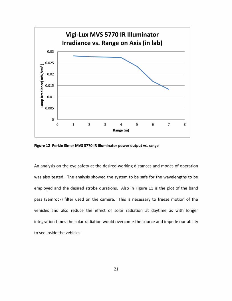
Figure 12 Perkin Elmer MVS 5770 IR Illuminator power output vs. range
An analysis on the eye safety at the desired working distances and modes of operation
was also tested. The analysis showed the system to be safe for the wavelengths to be
employed and the desired strobe durations. Also in Figure 11 is the plot of the band
pass (Semrock) filter used on the camera. This is necessary to freeze motion of the
vehicles and also reduce the effect of solar radiation at daytime as with longer
integration times the solar radiation would overcome the source and impede our ability
to see inside the vehicles.
0
0.005
0.01
0.015
0.02
0.025
0.03
0 1 2 3 4 5 6 7 8
Lam
p Ir
rad
ian
ce(
mW
/cm
2 )
Range (m)
Vigi-Lux MVS 5770 IR Illuminator Irradiance vs. Range on Axis (in lab)

22
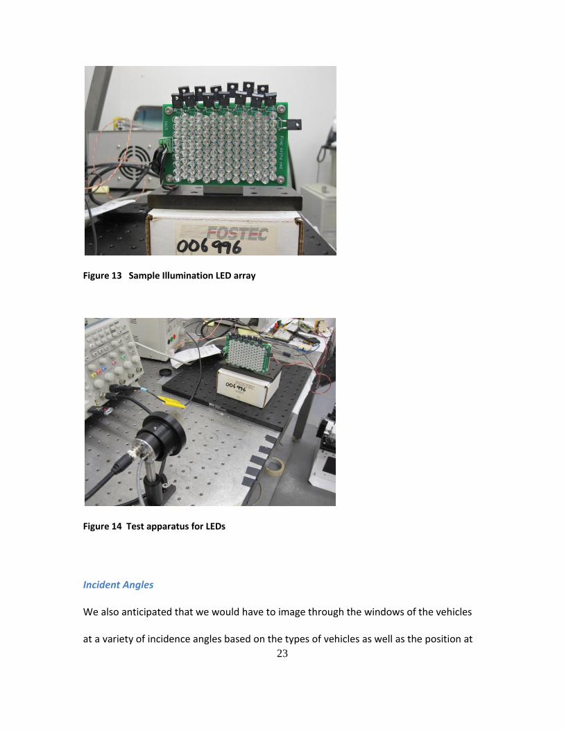
There was some concern about using the Xenon source in the long term both from the
viewpoint of the life of the device as well as the potential safety of the source. The main
safety concern is that since it is a filtered Xenon source if the filter is broken it could
potentially temporarily blind motorists. As mentioned earlier we looked at LEDs as
potential sources which would require us to drive them at fairly high currents to get the
power needed. The potential benefits would include a longer life as well as more
accurate control of both the illumination spectra as well as the on/off cycles. This
solution would also provide some flexibility in the form factors that could be used for
the illuminator to make it less observable. We therefore did some testing using a bank
of commercially available devices to estimate the numbers that would be needed to at
least match the Xenon strobe. We estimate that it would take ten of this bank of LEDs
running at high current to match the output from the Xenon strobe. Please see the
relevant section in the Appendix for more detail on the testing.
23
Figure 13 Sample Illumination LED array
Figure 14 Test apparatus for LEDs
Incident Angles
We also anticipated that we would have to image through the windows of the vehicles
at a variety of incidence angles based on the types of vehicles as well as the position at

24
which the image acquisition was triggered. We therefore did a study to access the
potential effects. This was accomplished by using the apparatus shown in Figure 15 to
image a black and white target to determine or ability to see the target at different
orientations.
Figure 15 Transmission measurements at various orientations
The results shown in Figure 16 and Figure 17 indicated that windshield angles up to
about 30 degrees in yaw or 45 degrees in pitch we don’t see appreciable changes in the
pixel values for the white and black pixels of the target. This means that for the
geometries under consideration the sensing should not be adversely affected by
windshield configuration.
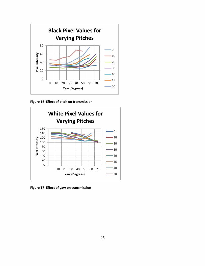
25
Figure 16 Effect of pitch on transmission
Figure 17 Effect of yaw on transmission
0
20
40
60
80
0 10 20 30 40 50 60 70
Pix
el I
nte
nsi
ty
Yaw (Degrees)
Black Pixel Values for Varying Pitches
0
10
20
30
40
45
50
0
20
40
60
80
100
120
140
160
0 10 20 30 40 50 60 70
Pix
el I
nte
nsi
ty
Yaw (Degrees)
White Pixel Values for Varying Pitches
0
10
20
30
40
45
50
60
26
PROCESSING ASPECTS
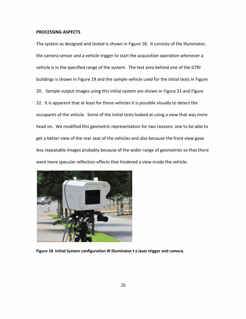
The system as designed and tested is shown in Figure 18. It consists of the illuminator,
the camera sensor and a vehicle trigger to start the acquisition operation whenever a
vehicle is in the specified range of the system. The test area behind one of the GTRI
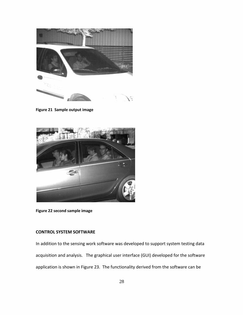
buildings is shown in Figure 19 and the sample vehicle used for the initial tests in Figure
20. Sample output images using this initial system are shown in Figure 21 and Figure
22. It is apparent that at least for these vehicles it is possible visually to detect the
occupants of the vehicle. Some of the initial tests looked at using a view that was more
head on. We modified this geometric representation for two reasons: one to be able to
get a better view of the rear seat of the vehicles and also because the front view gave
less repeatable images probably because of the wider range of geometries so that there
were more specular reflection effects that hindered a view inside the vehicle.
Figure 18 Initial System configuration IR illuminator t a laser trigger and camera.
27
Figure 19 System undergoing initial testing
Figure 20 GTRI Sample vehicle
28
Figure 21 Sample output image
Figure 22 second sample image
CONTROL SYSTEM SOFTWARE
In addition to the sensing work software was developed to support system testing data
acquisition and analysis. The graphical user interface (GUI) developed for the software
application is shown in Figure 23. The functionality derived from the software can be

29
discerned from the different GUI elements but allows for the acquisition and storage of
data in addition to the ability to run preliminary detection. Functionality was built into
the GUI in to allow for control of the camera and imaging parameters. The main form
controls whether any algorithms are to be performed on the input images and if the
output should be saved. The Camera tab is used for snapping a single image, saving a
single image, configuring the camera, and snapping and saving multiple images
automatically.
The software also operated in an offline mode as shown in Figure 23. This GUI in is
obtained by pressing the File tab on the first menu and is used for opening images in a
directory and scrolling through them, or just selecting and opening a single image. Both
options also implement the algorithm functionality and ability to view or save the
output image.

30
Figure 23 Graphical User Interface to control the system
Figure 24 Graphical User Interface for file viewing
IMAGE PROCESSING SOFTWARE
In conducting the evaluation one determining element would be the ability to
automatically process the images acquired to detect the presence of people in the
vehicles. This would be an integral part of the evaluation. Preliminary approaches to
conduct this analysis were done as part of the overall assessment.

31
SYSTEM TESTING
The next step was to obtain data for vehicles operating in their natural modes as would
be seen on the roadway or interstate. We were assisted by researchers in the
Department of Civil and Environmental Engineering at Georgia Tech to acquire data at
sites representative of a surface street on the Georgia Tech campus and also on an
interstate highway (Interstate 85 north of Atlanta). These two sites are shown in Figure
25 and Figure 26 respectively.
Figure 25 Georgia Tech Test Site
Figure 26 Interstate-85 Test Site
Street Testing
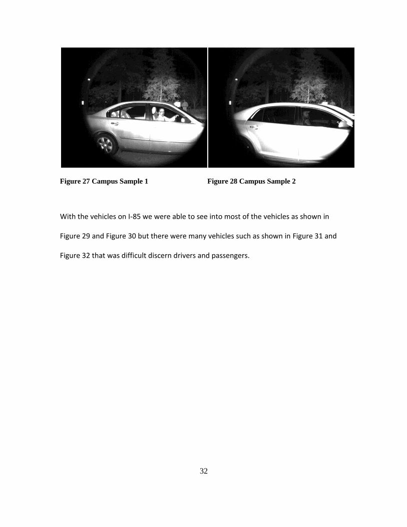
The samples from the Georgia Tech campus are shown in Figure 27 and Figure 28. With
the exception of a few missed triggers we seemed visually to be able to identify people
in the majority of vehicles.
32
Figure 27 Campus Sample 1
Figure 28 Campus Sample 2
With the vehicles on I-85 we were able to see into most of the vehicles as shown in
Figure 29 and Figure 30 but there were many vehicles such as shown in Figure 31 and
Figure 32 that was difficult discern drivers and passengers.

33
Interstate Testing
Figure 29 First I 85 Sample 1
Figure 30 First I 85 Sample 2
Figure 31 First I 85 Sample 3
Figure 32 First I 85 Sample 4

34
This data showed the system to be capable of acquiring data in vehicles at Interstate
highway speeds.
The system at the I-85 site is shown in Figure 26 and sample data is shown in Figure 29
to Figure 32 . It can be observed that it is possible to see the vehicle occupants example
in Figure 29 and Figure 30. We noticed however that for some vehicles such as shown in
Figure 31 and Figure 32 we were not able to penetrate the interior of the vehicles with
enough energy to be able to discern the occupants of the vehicles.
We suspected that the issue was the working distance to the vehicles at the I-85 site
which was on the order of 10 meters. We then did some further experiments to test
this hypothesis.
Distance and Illumination Tests
We suspected that the reason for the significant number of cars that we could not see in
was due to the working distance and the lower power that was being delivered into the
vehicle. We looked both the effect of the illumination pattern from the Xenon strobe
as well as the working distance.
Illumination Pattern Evaluation
During early testing, one issue that surfaced was that we were not getting enough light
onto target vehicles. We knew the output angle from the xenon strobe, and we
determined that we were overfilling the targets, losing light around them. Since we are
restricted as to how close we can get to the vehicles, we tested the idea of altering the
output of the strobe.
35
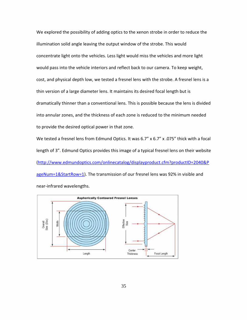
We explored the possibility of adding optics to the xenon strobe in order to reduce the
illumination solid angle leaving the output window of the strobe. This would
concentrate light onto the vehicles. Less light would miss the vehicles and more light
would pass into the vehicle interiors and reflect back to our camera. To keep weight,
cost, and physical depth low, we tested a fresnel lens with the strobe. A fresnel lens is a
thin version of a large diameter lens. It maintains its desired focal length but is
dramatically thinner than a conventional lens. This is possible because the lens is divided
into annular zones, and the thickness of each zone is reduced to the minimum needed
to provide the desired optical power in that zone.
We tested a fresnel lens from Edmund Optics. It was 6.7” x 6.7” x .075” thick with a focal
length of 3”. Edmund Optics provides this image of a typical fresnel lens on their website
(http://www.edmundoptics.com/onlinecatalog/displayproduct.cfm?productID=2040&P
ageNum=1&StartRow=1). The transmission of our fresnel lens was 92% in visible and
near-infrared wavelengths.

36
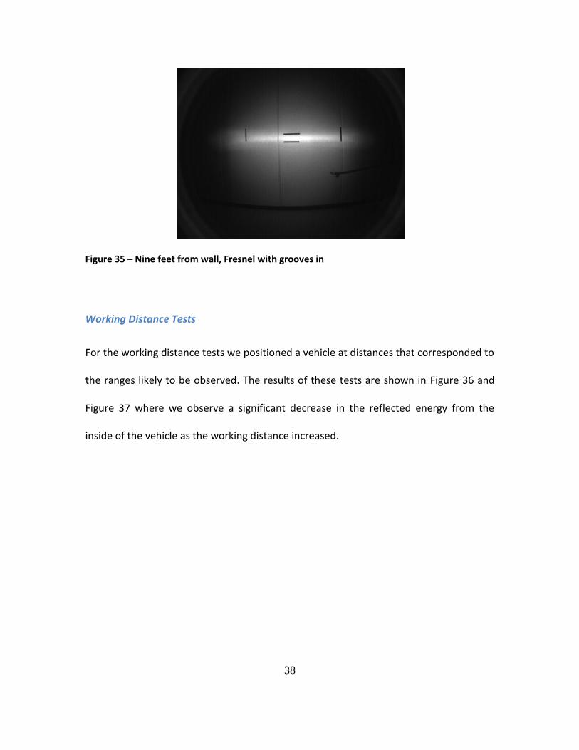
To test the effect of the fresnel, we setup the strobe in a large, open room where we
could control the ambient lighting. We aimed the strobe and camera at a wall nine feet
away to mimic our field conditions. We recorded images as the strobe fired. We placed
markers on the wall to indicate the edges of the illumination pattern. Control images
were collected without the fresnel lens. Then the fresnel was added, once with the
grooves pointed toward the strobe, once with them pointed away. The lens was
approximately one focal length from the strobe’s bulb. Our hypothesis was that the lens
would nearly collimate the light leaving the strobe. What we found, however, was that
the output dynamics of the strobe are complex. Not only does the strobe assembly
contain a slender, cylindrical bulb, it also incorporates a large cylindrical reflector. The
bulb and the reflector produced different effects through the fresnel lens, and the light
pattern that resulted was less desirable than the pattern without the strobe.
Examples shown in Figure 33, Figure 34, and Figure 35 are images captured of the wall
nine feet from the camera and strobe. It can be seen that the image without the fresnel
lens produced an illumination pattern that is rectangular and fairly homogeneous
though larger than we desire. The patterns with the fresnel are shapes that are not ideal
for our purposes, and they contain hot zones and shadows that would interfere with
image processing. Our conclusion was that a fresnel lens is not the best method of
concentrating light onto target vehicles.
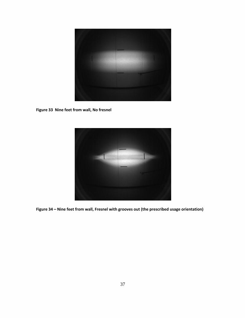
37
Figure 33 Nine feet from wall, No fresnel
Figure 34 – Nine feet from wall, Fresnel with grooves out (the prescribed usage orientation)
38
Figure 35 – Nine feet from wall, Fresnel with grooves in
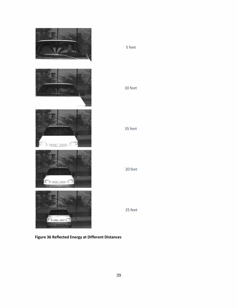
Working Distance Tests
For the working distance tests we positioned a vehicle at distances that corresponded to
the ranges likely to be observed. The results of these tests are shown in Figure 36 and
Figure 37 where we observe a significant decrease in the reflected energy from the
inside of the vehicle as the working distance increased.
39
Figure 36 Reflected Energy at Different Distances

40
Figure 37 Falloff in reflected energy intensity vs. distance
As a result we decided to conduct another test at working distances closer to the ones
likely to be used in a demonstration system with a working distance from the vehicles of
9 feet to 13 feet.
The results of these tests are shown in Figure 36 and Figure 37 where we observe a
significant decrease in the reflected energy from the inside of the vehicle as the working
distance increased. As a result we decided to conduct another test at working distances
closer to the ones likely to be used in a demonstration system (9 feet to 13 feet).
I-85 Test Number 2
We then made arrangements to return to the site to image on the exit ramp which
would allow for a geometric configuration that was closer to the campus setup and
more like what is likely to be experienced imaging from the median. Samples from this
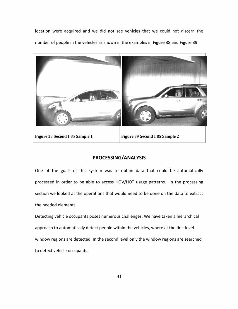
41
location were acquired and we did not see vehicles that we could not discern the
number of people in the vehicles as shown in the examples in Figure 38 and Figure 39
Figure 38 Second I 85 Sample 1
Figure 39 Second I 85 Sample 2
PROCESSING/ANALYSIS
One of the goals of this system was to obtain data that could be automatically
processed in order to be able to access HOV/HOT usage patterns. In the processing
section we looked at the operations that would need to be done on the data to extract
the needed elements.
Detecting vehicle occupants poses numerous challenges. We have taken a hierarchical
approach to automatically detect people within the vehicles, where at the first level
window regions are detected. In the second level only the window regions are searched
to detect vehicle occupants.

42
Based on the results of the background research into the detection algorithms, we
decided to look at four approaches for window regions and automated people
detection. The approaches chosen for investigation are: Chamfer matching, SIFT (Scale
Invariant Feature Transform) based detection, Haar and HOG features based detection.
A more detailed explanation of the techniques and their use are presented in Appendix
II.
In addition to the above mentioned methods, some other object detection algorithms
were also tested. In light of the performance of different algorithms, we decided to use
the HOG features for window detection and the Haar features for vehicle occupant’s
detection. Below we briefly summarize the advantages and disadvantages of the
algorithms tested.
The Chamfer matching based algorithm required no training. However it required a lot
of target object edge contours to give a reasonable detection performance. Having a
large set of object edge contours affected adversely the speed of the detection
algorithm. Moreover, catering for all the different shapes of the windows resulted in a
set of edge contours that gave much higher false positive rate. One thing that can be
done to improve the performance is to select the edges contours from among all
possible contours using Adaboost as is carried out in (Jamie, Blake, & Cipolla, 2005).

43
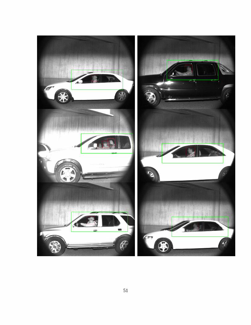
Sample images and their processed outputs using the approaches described earlier are
shown in. We demonstrated the ability to both locate the window regions of interest
and to locate the presence of passengers in the vehicles. Sample output is shown in
with more in Figure 40 where the region outlined in green identifies the window area of
the vehicle and the region outlined in red people located in these regions. More work
still needs to be done to automatically count people and also to assess vehicle
adherence to HOV/HOT operational guidelines.

44
Figure 40 Sample processed output green region window red region people
CONCEPT FOR DEMONSTRATION FIELD INSTALLATION
In order to fully prove out the concept for this system it would be beneficial to install a
demonstration system at a site that would be somewhat representative of a typical

45
HOV/HOT installation. We would like to suggest the site at the I-85 Pleasant Hill Road
exit ramp as a candidate. There are several reasons why this could potentially work
well.
There is an HOV lane
There is a Hub Building with power and network access
There are utilities located at the site
Hardware
The idea would be to have camera and illumination system located remotely on the
median at such a pose as to obtain the desired views into the vehicles. It might be
possible to use multiple cameras to obtain more complete views inside the vehicles and
to accommodate different vehicle types. These elements would then be connected to a
control computer that would be located in the hub building where direct access to the
GDOT and Georgia Tech Networks would be possible for system access as well as the
management and storage of data. A graphic of the proposed installation is shown in
Figure 41.
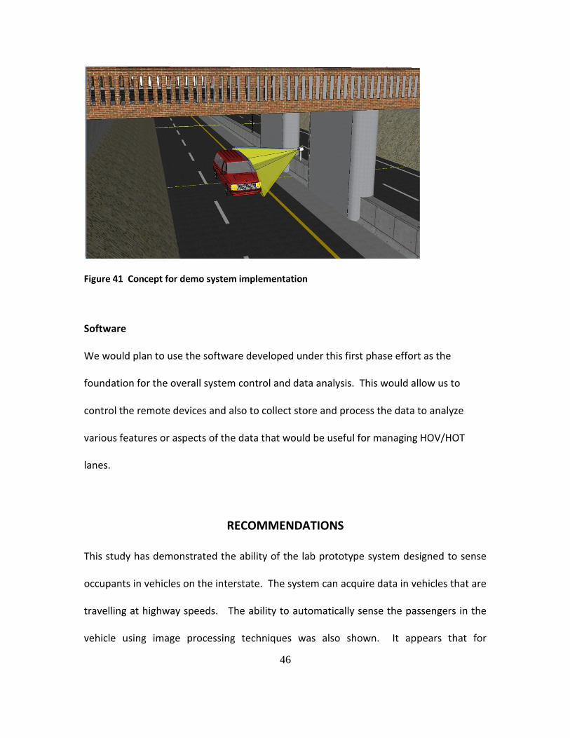
46
Figure 41 Concept for demo system implementation
Software
We would plan to use the software developed under this first phase effort as the
foundation for the overall system control and data analysis. This would allow us to
control the remote devices and also to collect store and process the data to analyze
various features or aspects of the data that would be useful for managing HOV/HOT
lanes.
RECOMMENDATIONS
This study has demonstrated the ability of the lab prototype system designed to sense
occupants in vehicles on the interstate. The system can acquire data in vehicles that are
travelling at highway speeds. The ability to automatically sense the passengers in the
vehicle using image processing techniques was also shown. It appears that for

47
HOV/HOT solutions a view that is somewhat from the sides of the vehicle appears to
give more reliable images in addition to allowing for improved observation of the rear
seats which would be required for HOT applications as planned in Georgia. We have
also looked at an alternate means of illumination using high powered LEDs. This
appears to be a possibility and would provide aspect ratios for the system that might
make it less obtrusive while reducing the possibility of distraction from the illumination
pulse.
The approach described appears to be technically feasible and we recommend an
evaluation at a representative HOV/HOT site such as the Pleasant Hill Road exit on I-85.

48
REFERENCES
1. Goodin, G. Enforcement of Managed Lanes with HOV Preference. in 12th International HOV Systems Conference: Improving Mobility and Accessibility with Managed Lanes, Pricing, and BRT, 2005. Houston, Texas.
2. Loudon, W.R. Improving the Estimation of Potential Travel-Time Savings from HOV Lanes. in Transportation Research Board 86th Annual Meeting. 2007. Washington, D.C.
3. Munnich, L.W. and K.R. Buckeye. I-394 MnPASS High-Occupancy Toll Lanes: Planning and Operational Issues and Outcomes (Lessons Learned in Year One). in Transportation Research Board 86th Annual Meeting. 2007. Washington, D.C.
4. Poole, R., A New Solution for HOV Occupancy Enforcement, in Surface Transportation Innovation. 2007.
5. Schijns, S. and P. Matthews. Automated Occupancy Monitoring Systems for HOV/HOT Monitoring and Enforcement. in 12th International HOV Systems Conference Improving Mobility and Accessibility with Managed Lanes, Pricing, and BRT. 2005. Houston, Texas.
6. Siegal, R. Arizona May Open HOV Lanes to Lone Drivers. 2007 [cited 2007 February 14, 2007]; Available from: http://www.npr.org/templates/story/story.php?storyId=7407266.
7. TTI, T.T.I., Automated Vehicle Occupancy Technologies Study (Draft Synthesis Report). 2006. p. HOV Pooled-Fund Study Current Projects.
8. Turnbull, K.F. HOV Lanes and Hybrid Vehicles. in Transportation Research Board 86th Annual Meeting, 2007. Washington, D.C.

49
BIBLIOGRAPHY
Dalal, N., & Triggs, B. (2005). Histograms of Oriented Gradients for Human Detection.
Computer Vision and Pattern Recognition.
Fulkerson, B., Vedaldi, A., & Soatto, S. (2009). Class Segmentation and Object
Localization with Superpixel Neighborhoods. International Conference on Computer
Vision.
Gavrilla, D. (1998). Multi-feature hierarchical template matching using. ICPR, (pp. 439-
444).
Hao, X., Chen, H., Yao, C., Yang, N., Bi, H., & Wang, C. (2010). A near-infrared imaging
method for capturing the interior of a vehicle through windshield. IEEE Southwest
Symposium on Image Analysis and Interpretation.
http://www.vehicleoccupancy.com.
Jamie, S., Blake, A., & Cipolla, R. (2005). Contour-Based Learning for Object Detection.
International conference on computer vision.
Viola, P., & Jones, M. (2001). Rapid object detection using a boosted cascade of simple
features. Computer Vision and Pattern Recognition.
Wood, J., Gimmestad, G., & Roberts, D. (2003). Covert camera for screening of vehicle
interiors and hov enforcement. SPIE-The international Society for optical Engineering.
50
APPENDICES
Appendix I: Sample Output Images
51
52
Appendix II: Software Design
GEORGIA TECH RESEARCH INSTITUTE – FPTD
H.O.V. Sensing Software Design Document
HOV Project Team
9/6/2010
53
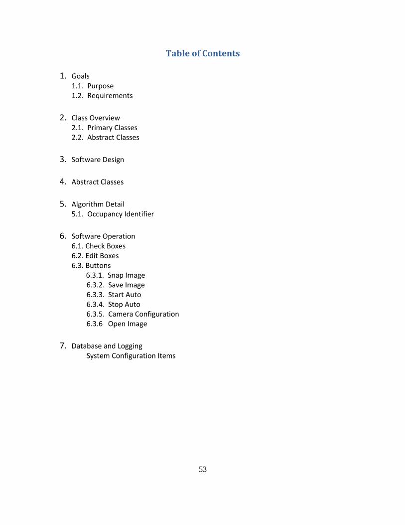
Table of Contents
1. Goals 1.1. Purpose 1.2. Requirements
2. Class Overview
2.1. Primary Classes 2.2. Abstract Classes
3. Software Design
4. Abstract Classes
5. Algorithm Detail
5.1. Occupancy Identifier
6. Software Operation
6.1. Check Boxes 6.2. Edit Boxes 6.3. Buttons 6.3.1. Snap Image 6.3.2. Save Image 6.3.3. Start Auto 6.3.4. Stop Auto 6.3.5. Camera Configuration 6.3.6 Open Image
7. Database and Logging
System Configuration Items

54
1. Goals
Purpose
The “H.O.V. Occupancy Sensing” project is primarily designed to detect HOV lane
utilization. This is performed by using an imaging system to identify and calculate the
number of occupants in vehicles in the HOV lanes in Atlanta, GA.
Requirements
Snap and save images of vehicles in motion at speeds up to 80 mph at rate of 1 per second
Allow for review/processing of images saved
Stub for processing images that can be modified as techniques are developed and enhanced
Allow settings to be modified from xml file(s)
Modify settings for trigger??
Support for setup/configuration??
1. Class Overview
Primary Classes
These provide the core functionality such as a graphical user interface, database
functionality, and configurability through an XML configuration file.
HOV_Sensing – Creates the application instance and instantiates the dialog
HOV_SensingDlg – Creates, draws, and handles all dialog Interactions
XMLConfiguration – Handles reading/writing configuration parameters
QueueData – Handles logging of data to a database
TabCtrl – initializes and controls dialogs within the tab control
CameraDlg – first tab; handles camera operations (start, stop, snap, save, config)
FileDlg – second tab; opens and scrolls through images from file

55
Abstract Classes
These classes all inherit from one of two base classes, GenericCamera and
ProcessorInterface. This allows for changing the acquisition method or processing
engine with minimal software development overhead.
Generic Camera – Generic camera interface that is allows easy switching of hardware without changing any software calls (will have to change included interfaces).
o GenericCamera – the generic class that includes very basic functionality that all cameras share.
o GenericImage Format – o GenericCameraException – Exception class used for error handling
PGRCamera – Internally (FPTD) written PointGrey Research Cameras class that inherits from GenericCamera. It also contains a great deal of additional functionality specific to PointGrey cameras. Uses PointGrey’s FlyCapture2.0 library to communicate with the camera.
o CameraInternal – Class hidden to the user. It includes and uses the FlyCapture2 library. By using this “hidden” class, the end user only needs to include CameraExternal and the PGRCamera library in their project and do not have to include or link to any of the PointGrey source code.
o CameraExternal – What the end user includes in the project and uses to access the camera. It merely “forwards” its calls to CameraInternal.
o CameraDefinitions – A file to declare definitions that are used in the camera classes.
ProcessorInterface o OccupancyIdentifier
56
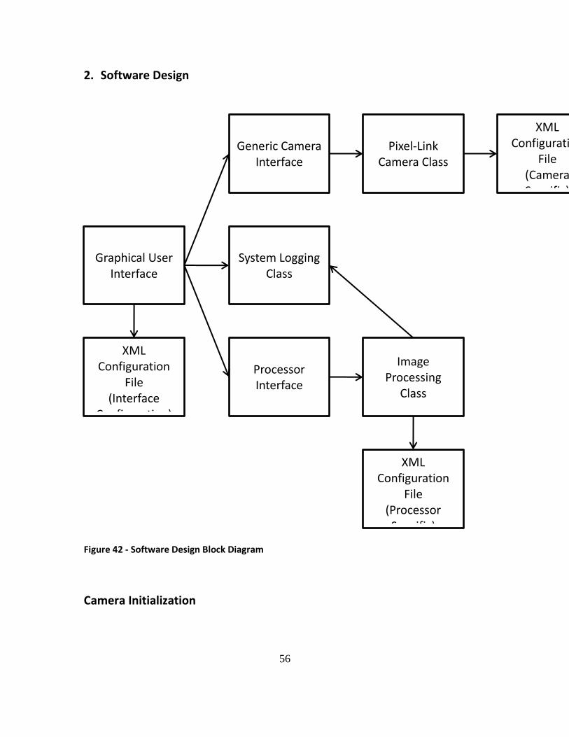
2. Software Design
Figure 42 - Software Design Block Diagram
Camera Initialization
Generic Camera Interface
Pixel-Link Camera Class
Graphical User Interface
Processor Interface
Image Processing
Class
XML Configuration
File
(Interface Configuration)
XML Configuration
File
(Processor Specific)
System Logging Class
XML Configuration
File
(Camera Specific)

57
There are several steps to setting up the camera. The reasons behind them are detailed
in Appendix II. There are two categories of parameters to initialize, Camera Settings and
hardware parameters.
The current camera settings initialized are:
Setting Value
Shutter .16 ms
Gain 22 dB
All others (Brightness, Exposure, Gamma, etc) are turned off.
The hardware initialization is done next. It sets the camera into the correct trigger
mode, sets up the external trigger and strobe, and sets the delays and durations to their
ideal values.
Additionally, the snap call actually turns the strobe on and off to prevent the light
source from triggering when the system is not taking a picture.
Software Operation
The program is a Dialog Based MFC program; therefore, all functionality is driven by
user interaction (button clicks, check boxes, etc.) A single function named DoProcess

58
will perform the actual image processing tasks required by the system. Figure 2 shows a
flowchart of the DoProcess Functionality. Figures 3 and 4 illustrate the dialog. The
following sub-sections will detail the functionality of each button, edit box, and check
box, using flowcharts where appropriate.
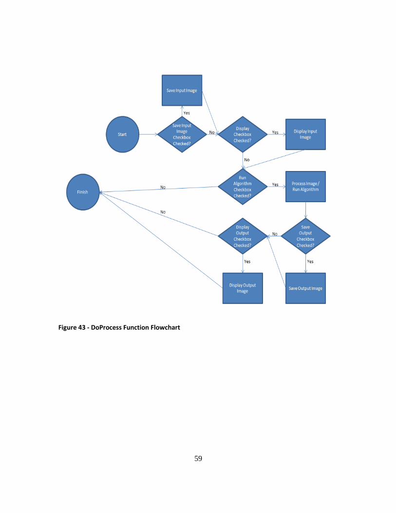
59
Figure 43 - DoProcess Function Flowchart
60
Figure 44 - Program Dialog with Camera Option
Figure 45 - Program Dialog with File Loading Option
Check Boxes
Show Input Image – Check box to toggle display for input (raw) image
Show Output Image – Check box to toggle display of processed image
Run Algorithm – Check box to enable image processing algorithm
Save Auto – Checkbox to enable saving all raw images in auto mode

61
Save Output – Check box to save output images (single snap and auto mode)
Edit Boxes
Save Directory – Set location to save files (separate selection for input and output images)
Image Name (suffix) – Enter an optional suffix to append to save file names
Current Image – Displays name of current image (for loading files functionality only)
Digits – Number of digits to use in file name
Image Directory – Set the directory from which to load images
Buttons
1. Snap Image
The Snap Image button will snap a single image from the camera and pass the captured
image into the function DoProcess(Image).
2. Save Image
The Save Image button will check if there is a valid image buffer. Upon success, it will
open a file save dialog allowing the user to specify a filename and save the image as a
.BMP. If there is no valid image buffer, meaning no image has been snapped, a message
box will report that there is not a valid image buffer to save.
3. Start Auto
The Start Auto button will create a timer that will fire once a second (user configurable).
Each time the timer fires, the Snap Image functionality will be activated (See Snap Image
Button 4.3.1).

62
4. Stop Auto
The Stop Auto button will kill the timer spawned in Start Auto (4.3.3). This will stop the
system from automatically acquiring images.
5. Camera Configuration
The Camera Configuration button will spawn a configuration dialog for the related
system. In this case, it is a PGR camera dialog. This allows the user to change camera
parameters from the HOV Sensing program.
6. Open Image
The Open Image button will open a single file selection dialog allowing the user to select
a .BMP file. Upon success, the file will be loaded and DoProcess(Image) will be called
with the loaded image as a parameter.
Algorithm Detail
Details on the algorithms are presented in Appendix III.

63
Appendix III: Image Processing Approaches
High Occupancy Vehicle People Detection
Background
Detecting and automatically counting vehicle occupants using a visual camera pose
numerous challenges such as reflection from the windshield, different operation
conditions, and shadows. Most of the work in this regard uses a combination of visual
and near infra-red (NIR) range. NIR is almost completely transmitted by the vehicle
windshields. Following is a brief description of the state of the art in automatic
detection of vehicle occupants.
Dtect provides a commercially available automated system for determining the number
of occupants within moving road vehicles (http://www.vehicleoccupancy.com.) The
system projects two low intensity beams of Infrared (IR) light of different wavelengths
onto the vehicle. Two digital photos are taken and merged to produce a single image
and then processed by software based algorithms to detect the number of people.
Similarly in (Hao, Chen, Yao, Yang, Bi, & Wang, 2010), the authors use the near infra-red
(NIR) illuminator to illuminate the interior of the car and a digital photo is captured
using a camera equipped with an NIR filter. This setup reduces the effect of reflection of
light from the windshield of the car. The captured photo can be viewed by a human
screener or processed by computer vision algorithms to determine the number of
occupants. Other work that uses the NIR range is (Wood, Gimmestad, & Roberts, 2003).
64
Alternate to NIR range is to use thermal imaging systems to detect occupants using their
heat map. However the use of athermic metallic coatings on the glass prevents the
penetration of these wavelengths through the windshield.
Algorithms
Detecting vehicle occupants poses numerous challenges. We have taken a hierarchical
approach to automatically detect people within the vehicles, where at the first level
window regions are detected. In the second level only the window regions are searched
to detect vehicle occupants.
Based on the results of the background research into the detection algorithms, we
decided to look at four approaches for window regions and automated people
detection. The approaches chosen for investigation are: Chamfer matching, SIFT (Scale
Invariant Feature Transform) based detection, Haar and HOG features based detection.
A more detailed explanation of the techniques and their use are presented in the next
section.
Chamfer Matching Based Window Detection.
Chamfer matching measures the distance between a template edge map and the edge
map of a given input image and uses a sliding window approach to measure distance
over whole of the image. The distance between the two edge maps can be effectively
computed using a distance transform (Gavrilla, 1998) of the given input image. Each
pixel value in the distance transform image is the distance to the closest edge in the

65
edge map of the input image. Figure 1 shows an input image, its edge map, distance
transform (the log of distance transforms is shown for better visualization), and the
chamfer matching score using a template of the window region.
To account for different size and shape of the vehicle windows, a variation of the
chamfer matching is used. It is explained below.
a) Generating template contours:
Instead of using a single edge template, the target object edge map is divided into number of different parts (Jamie, Blake, & Cipolla, 2005). Each part can translate and rotate around its origin, depending upon the variability in shape of the target object. Figure 2 shows the example of template used to detect windows of vehicles, where the template is divided into different line segments.
Figure 1 Input Image, edge map, distance transform and chamfer score.

66
b) Chamfer matching:
The search window (equal to the size of the template) is moved across the image. At each search location, the distance of each of the line segments to the edge map is computed using the distance transform. From each group of line segments, a line segment is chosen that gives the smallest chamfer score. The chamfer score of the search window is then computed by taking the sum of the chamfer scores of the chosen line segments from each group. The search window that gives the smallest distance is taken as the location of
the object in the image.
Super pixel Segmentation using SIFT
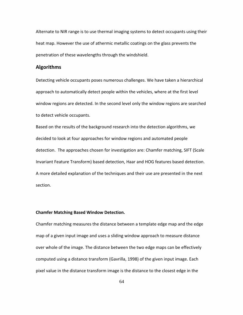
In the second method we looked at an algorithm that will give us the segmentation of
the target objects (window, people) and not just the rectangular boundary. This method
comprised of the following steps (Fulkerson, Vedaldi, & Soatto, 2009).
a) Super pixels segmentation:
The image is preprocessed to group similar pixels into super pixels. Mean shift algorithm is used to extract the super pixels from the input image. Examples of input image and its super pixel segmentation are shown in Figure 3. The super pixel segmentation consists of regions that preserve the boundaries in the original image. b) Scale Invariant Feature Transform (SIFT) descriptors extraction:
The next step is to extract from each super pixel a feature descriptor. For every ith pixel in the input image, SIFT features are extracted at a fixed orientation and scale. The extracted descriptors are then quantized using a K-means dictionary (formation of K-means dictionary is explained in the next step). For each super pixel, all the quantized descriptors are aggregated into one L1 normalized histogram. The final descriptor for each super pixel is obtained by
Figure 46: Example template for window detection. Figure 2 Example template for window detection.

67
merging the histograms of N neighboring super pixels and normalizing the result. Figures 4 shows the location where SIFT features are extracted (not all locations are shown), along with the SIFT descriptors for two of the locations in Figure 4b. Figure 4c shows a super pixel with SIFT features, whose normalized histogram is shown in Figure 4d.
c) K-means dictionary:
To build a K-means dictionary for quantizing the SIFT descriptors, SIFT descriptors are extracted for each pixel from a set of training images. K-means clustering is performed with K=100. To build a histogram for a super pixel using this K-means based dictionary, SIFT descriptors within a super pixel are aggregated to the K bins of the histogram corresponding to the least distance of the descriptor to the cluster centers.
Figure 4 a-d Input images and mean shift based super pixel segmentation.
68
d) Learning using SVM:
The positive and negative samples of super pixels are extracting from training images. Descriptor histogram of each super pixel is assigned a 1 or 0 depending upon whether it belongs to the object region or the background. This is then trained using SVM. During detection phase, histograms of super pixels are extracted and then fed to the SVM, which spits out the class labels.
e) Refinement using Graph cut:
Each super pixel is assigned a 1 or 0 by the SVM independently from neighboring super pixels. Graph cut is used to spatially link the neighboring super pixels, which smoothers the resulting segmentation.
Figure 5 : First row – location of SIFT features and two SIFT descriptors at two sample locations. Second row – super pixel with SIFT locations and the descriptor histogram for the super pixel.

69
HaarCascade Classifier (Face and Window)
Haar-like features compute the oriented contrasts between regions in the image using
simple rectangular features. The rectangular features consist of two sub rectangles:
one corresponds to a high interval and the other to low interval. The presence of Haar
feature is determined by subtracting the average intensity value of the high region from
the low region. If the difference is higher than a threshold value, that feature is present
in that region. OpenCV implementation of Haar-like features “HaarCascade classifier” is
used for face and window detection (Viola & Jones, 2001).
a) Training:
First a set of positive and negative image regions is generated. Positive samples were generated manually from the training images. For negative samples, regions in the image were selected that contained no positive samples. Examples of positive samples of faces and window regions are shown in Figure 5.
The locations and the type of Haar features are selected using AdaBoost. Adaboost combines many weak classifiers (Haar features with threshold) to create one strong classifier. The strong classifiers learned using Adaboost are arranged in a cascade in the order of complexity, where each successive
Figure 6 Examples of positive training samples.

70
strong classifier is trained using samples that pass through the preceding strong classifiers.
b) Detection:
During the detection phase, the search window is moved across the image at multiple scales. At each location, the cascade classifier is evaluated. If at any stage the cascade classifier rejects the region, no further classifiers in the cascade are processed and the search window is moved to the next location. The object is detected in a region if the region is not rejected by any classifier.
Histogram of Orientated Gradients (HOG).
This method using dense HOG features (Dalal & Triggs, 2005). The image window is
divided into a number of small spatial regions (cells). For each cell a histogram of
oriented gradients is computed. For better invariance to illumination changes, the
histogram is normalized using larger spatial regions (blocks). The histogram from all the
cells are concatenated into one vector called the HOG descriptor of the window region.
a) Training:
First a set of positive and negative image regions is generated. Positive samples were generated manually from the training images. For negative samples, regions in the image were selected that contained no positive samples. HOG descriptors are computed for all the positive and negative window regions. Binary support vector machine (SVM) is used to distinguish the positive samples from the negative ones.
b) Detection:
During the detection phase, the search window is moved across the image. At each location the HOG descriptor is computed for the window region. The HOG descriptor is passed onto the SVM, which classifies the window region into object or background.

71
Summary
In addition to the above mentioned methods, some other object detection algorithms
were also tested. In light of the performance of different algorithms, we decided to use
the HOG features for window detection and the Haar features for vehicle occupant’s
detection. Below we briefly summarize the advantages and disadvantages of the
algorithms tested.
The Chamfer matching based algorithm required no training. However it required a lot
of target object edge contours to give a reasonable detection performance. Having a
large set of object edge contours affected adversely the speed of the detection
algorithm. Moreover, catering for all the different shapes of the windows resulted in a
set of edge contours that gave much higher false positive rate. One thing that can be
done to improve the performance is to select the edges contours from among all
possible contours using Adaboost as is carried out in (Jamie, Blake, & Cipolla, 2005).
The pixel-wise segmentation algorithm using SIFT didn’t perform well in all cases. Some
of the results are shown in Figure 7, where red contour is the window detected by the
algorithm.
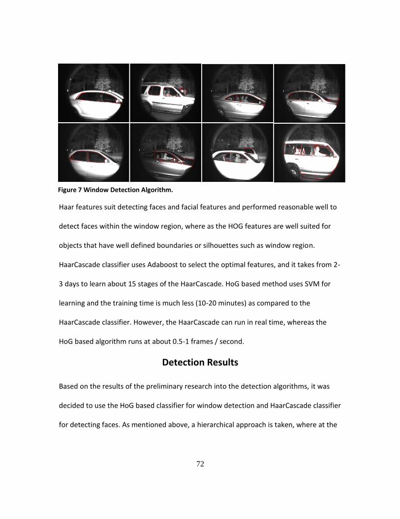
72
Haar features suit detecting faces and facial features and performed reasonable well to
detect faces within the window region, where as the HOG features are well suited for
objects that have well defined boundaries or silhouettes such as window region.
HaarCascade classifier uses Adaboost to select the optimal features, and it takes from 2-
3 days to learn about 15 stages of the HaarCascade. HoG based method uses SVM for
learning and the training time is much less (10-20 minutes) as compared to the
HaarCascade classifier. However, the HaarCascade can run in real time, whereas the
HoG based algorithm runs at about 0.5-1 frames / second.
Detection Results
Based on the results of the preliminary research into the detection algorithms, it was
decided to use the HoG based classifier for window detection and HaarCascade classifier
for detecting faces. As mentioned above, a hierarchical approach is taken, where at the
Figure 7 Window Detection Algorithm.

73
first level vehicle window regions are detected using a HoG classifier. In the second level
the detected window region is searched for faces using a HaarCascade classifier.
To train the classifiers, training images were taken at different sites. The training images
were used to extract the features (HoG for window and Haar-like features for faces),
which were then learned/selected using SVM and adaboost respectively. The trained
classifiers were then tested on a new set of images taken from a different site.
The test set consisted of 114 images. In six of the images, the laser trigger timing was off
a little. As a result, either the back or the front half of the vehicle was captured. For the
remaining 108 images, the table below shows the detected, missed and false positive
window regions and occupants. For window region the detection rate was 97% and the
detection rate for the occupants was 87%.
Window Detected 105
Missed 3
False Positive 5
Occupants Detected 100
Missed 15
False Positive 24
Figure 8 shows some of the detection results. The green rectangle shows the detected
window region and the red rectangle shows the detected faces. Please see the Appendix
A for more images.
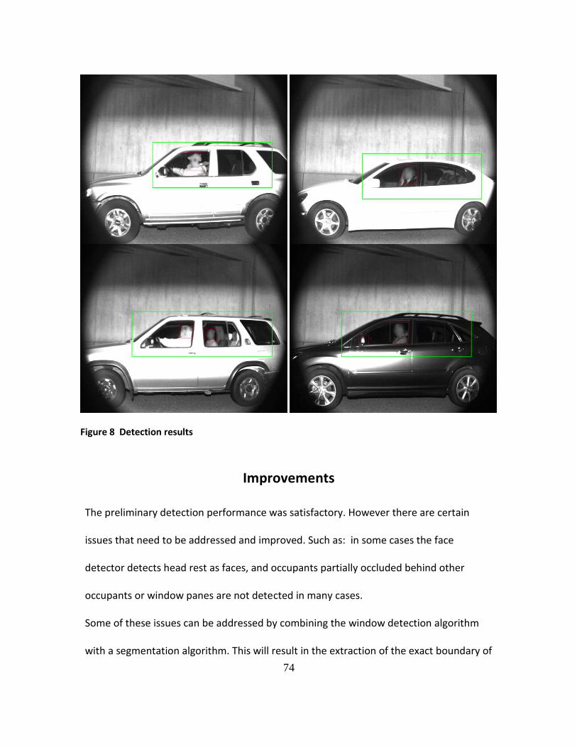
74
Improvements
The preliminary detection performance was satisfactory. However there are certain
issues that need to be addressed and improved. Such as: in some cases the face
detector detects head rest as faces, and occupants partially occluded behind other
occupants or window panes are not detected in many cases.
Some of these issues can be addressed by combining the window detection algorithm
with a segmentation algorithm. This will result in the extraction of the exact boundary of
Figure 8 Detection results

75
the window. The face detector when run within this boundary region should be able to
reject many false positives based on where they occur within the window region.
Additionally, if training and testing samples are generated from the same site, the
detection performance can be improved considerably. Also, the detection performance
can be improved if the imaging device is tuned to give a more uniform image from
vehicle to vehicle.
Another issue that needs to be addressed is that the laser did not trigger in a timely
manner in about 10% of the vehicles. In some cases it triggered late and in some it did
not trigger at all. Mostly these were dark and shiny color vehicles. During the
experiments it was noted that if the distance between the laser and the vehicle is more
than 15m, the laser captured 100% of the vehicles. At closer distances, about 10% of the
vehicles are missed. We think it is due to the use of round (pencil) laser beam. At
shorter distances the laser beam is too focused and sometimes may hit the vehicle at an
angle where all light is scattered and nothings reflects back. This problem can be
alleviated by using a fanned laser module, which forces the beam to diverge in the
vertical plane. In the horizontal plane, the laser beam remains collimated. Figure 9
shows a picture of fanned laser module.
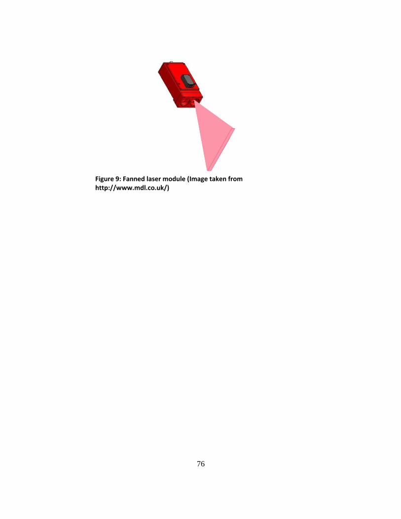
76
Figure 9: Fanned laser module (Image taken from http://www.mdl.co.uk/)

77
BIBLIOGRAPHY
Dalal, N., & Triggs, B. (2005). Histograms of Oriented Gradients for Human Detection. Computer
Vision and Pattern Recognition.
Fulkerson, B., Vedaldi, A., & Soatto, S. (2009). Class Segmentation and Object Localization with
Superpixel Neighborhoods. International Conference on Computer Vision.
Gavrilla, D. (1998). Multi-feature hierarchical template matching using. ICPR, (pp. 439-444).
Hao, X., Chen, H., Yao, C., Yang, N., Bi, H., & Wang, C. (2010). A near-infrared imaging method for
capturing the interior of a vehicle through windshield. IEEE Southwest Symposium on Image
Analysis and Interpretation.
http://www.vehicleoccupancy.com.
Jamie, S., Blake, A., & Cipolla, R. (2005). Contour-Based Learning for Object Detection.
International conference on computer vision.
Viola, P., & Jones, M. (2001). Rapid object detection using a boosted cascade of simple features.
Computer Vision and Pattern Recognition.
Wood, J., Gimmestad, G., & Roberts, D. (2003). Covert camera for screening of vehicle interiors
and hov enforcement. SPIE-The international Society for optical Engineering.
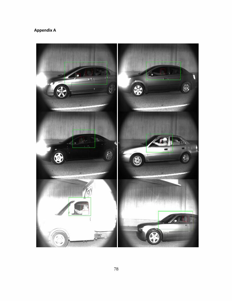
78
Appendix A
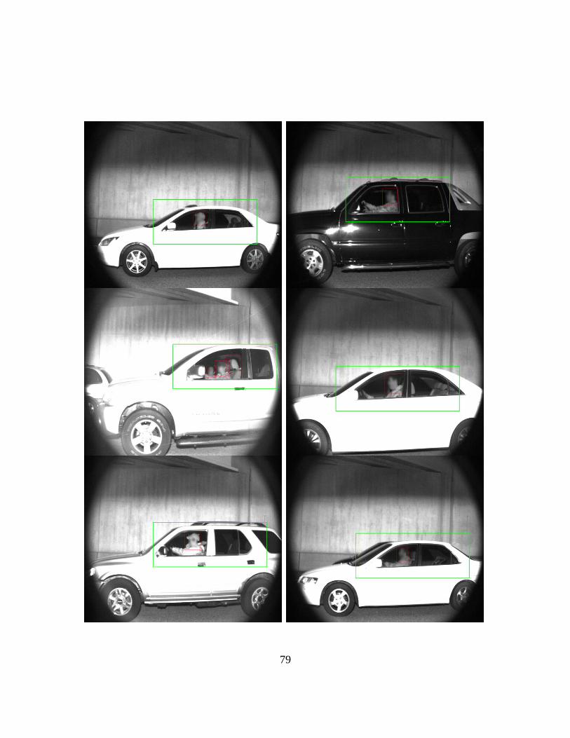
79

80

81
Appendix IV: LED Evaluation
Assessing Power Requirements for Prototype LED Board
To measure the current travelling through a string of LED I measured the voltage across
a 2 Ohm resister in an LED string using the Fluke 192B Scopemeter (battery powered
oscilloscope). The battery powered oscilloscope must be used on these boards because
of the way the strobe circuit is built. The LED board’s “+” is wired to VCC while its “–“ is
connected to a transistor that provides a path to ground when the transistor is
activated. If an oscilloscope that shares an earth ground with the power supply is used,
the LEDs will be on simply by being connected to the oscilloscope (having a path to
ground) and will burn out in a matter of seconds (meant to be strobed at only 100-150
microseconds at 1 amp). The Fluke measured roughly 2 volts (see image below) over
the 150 microseconds the LEDs were on. Using Ohms Law (V = IR), we can calculate the
amperage (I = V \ R). I = 2 \ 2 = 1 amp. A voltage of 29 volts was used to drive the LEDs
for this test. One board consisting of 14 strings of LEDs require 14 amps at 29 volts to
maximize light output while not burning itself out.
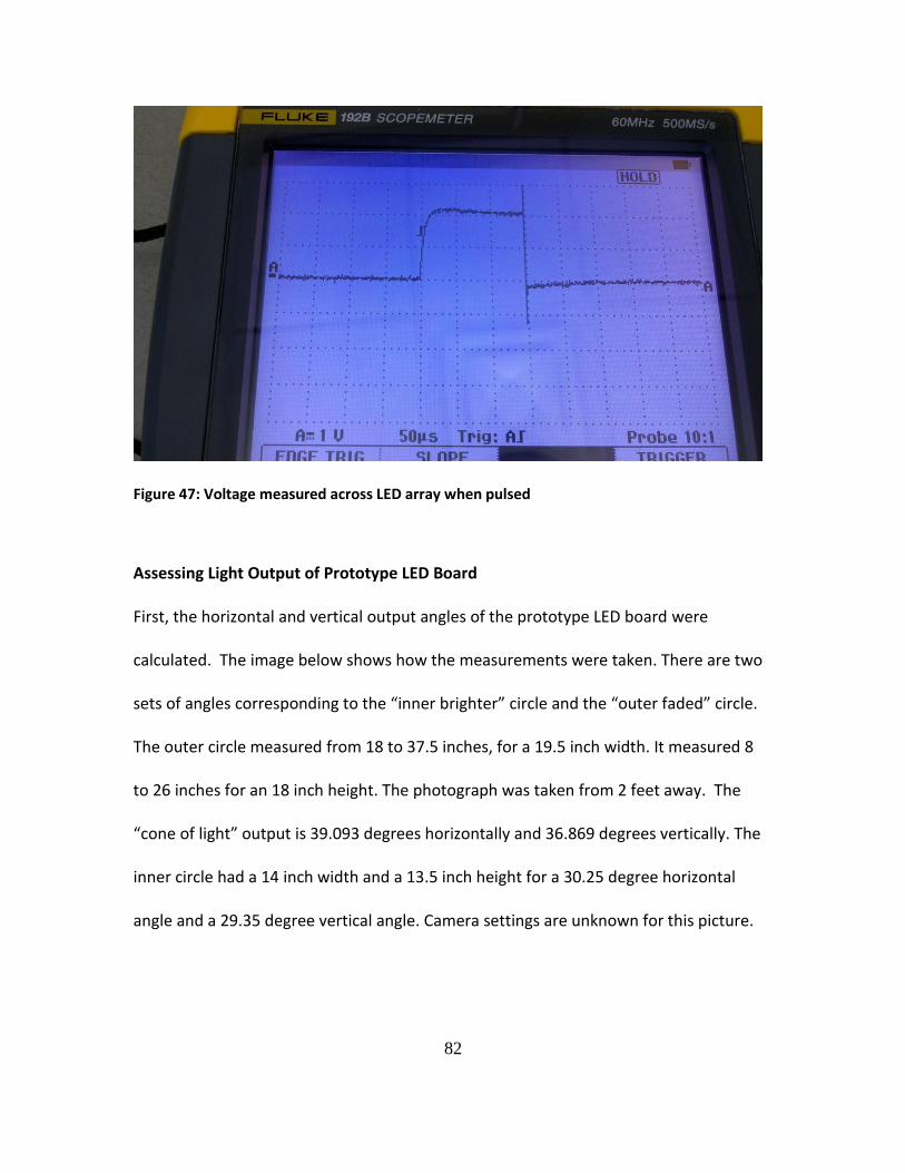
82
Figure 47: Voltage measured across LED array when pulsed
Assessing Light Output of Prototype LED Board
First, the horizontal and vertical output angles of the prototype LED board were
calculated. The image below shows how the measurements were taken. There are two
sets of angles corresponding to the “inner brighter” circle and the “outer faded” circle.
The outer circle measured from 18 to 37.5 inches, for a 19.5 inch width. It measured 8
to 26 inches for an 18 inch height. The photograph was taken from 2 feet away. The
“cone of light” output is 39.093 degrees horizontally and 36.869 degrees vertically. The
inner circle had a 14 inch width and a 13.5 inch height for a 30.25 degree horizontal
angle and a 29.35 degree vertical angle. Camera settings are unknown for this picture.
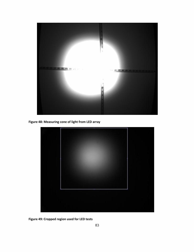
83
Figure 48: Measuring cone of light from LED array
Figure 49: Cropped region used for LED tests
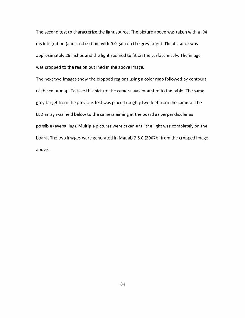
84
The second test to characterize the light source. The picture above was taken with a .94
ms integration (and strobe) time with 0.0 gain on the grey target. The distance was
approximately 26 inches and the light seemed to fit on the surface nicely. The image
was cropped to the region outlined in the above image.
The next two images show the cropped regions using a color map followed by contours
of the color map. To take this picture the camera was mounted to the table. The same
grey target from the previous test was placed roughly two feet from the camera. The
LED array was held below to the camera aiming at the board as perpendicular as
possible (eyeballing). Multiple pictures were taken until the light was completely on the
board. The two images were generated in Matlab 7.5.0 (2007b) from the cropped image
above.

85
Figure 50 Colormap of intensity values for LED array

86
Figure 51: Contours of colormap for LED array
Comparing Prototype LED Board with MVS-5770F-01
For this experiment the THORLABS PDA520 light meter and Tektronix TDS 2042B
oscilloscope were used and set up in the following manner (image below). Thor Lab’s
neutral density (ND) filters were placed in front of the light meter until a non-saturated
reading was taken. The test was done for the led array and the MVS-5770F-01 and the
results are shown on the following graphs.

87
Figure 52: Experiment Setup
-0.5
0
0.5
1
1.5
2
2.5
-0.0
00
5-0
.00
04
56
4-0
.00
04
12
8-0
.00
03
69
2-0
.00
03
25
6-0
.00
02
82
-0.0
00
23
84
-0.0
00
19
48
-0.0
00
15
12
-0.0
00
10
76
-6.4
E-0
5-2
.04
E-0
50
.00
00
23
26
.68
E-0
50
.00
01
10
40
.00
01
54
0.0
00
19
76
0.0
00
24
12
0.0
00
28
48
0.0
00
32
84
0.0
00
37
20
.00
04
15
60
.00
04
59
2
Vo
lts
Time
LED Array Light Source
ND 2.0, 1.0
Light Source
Light Meter
12 in
Neutral Density Filters
IR filter

88
The areas under the graphs during the pulses are 0.000611 for the MVS-5770F and
0.000422 for the LED array. The filters used were 2.0, 1.0, 0.5, 0.3, 0.2 for the MVS-5770
and 2.0, 1.0 for the LED array.
The power for the MVS-5770F would be 0.000611 * 10^2 * 10^1 * 10^.5 * 10^.3 * 10^.2
= .000611 * 100 * 10 * 3.1622 * 1.999 * 1.585 = 6.122
The power for the LED array would be 0.000422 * 10^2 * 10^1 = .422
Per unit area, the MVS-5770F is roughly 6.122 / .422 or 14.507 times stronger (where
the area is the surface area of the light meter.)
Now we need to take account the area projected by the light sources. I will use 10 feet
as the distance (math easier).
-0.5
0
0.5
1
1.5
2
2.5
3
3.5
4
4.5
-0.0
00
5-0
.00
04
56
4-0
.00
04
12
8-0
.00
03
69
2-0
.00
03
25
6-0
.00
02
82
-0.0
00
23
84
-0.0
00
19
48
-0.0
00
15
12
-0.0
00
10
76
-6.4
E-0
5-0
.00
00
20
40
.00
00
23
26
.68
E-0
50
.00
01
10
40
.00
01
54
0.0
00
19
76
0.0
00
24
12
0.0
00
28
48
0.0
00
32
84
0.0
00
37
20
.00
04
15
60
.00
04
59
2
Vo
lts
Time
MVS-5570F-01 Light Source
ND 2.0, 1.0, 0.5, 0.3, 0.2

89
The MVS-5770F outputs a rectangular pattern of 75 by 25 degrees. At 10 feet, it would
project a 15.347 by 4.434 foot rectangle for a 68.047 foot area.
The LED array outputs a 30.25 by 29.35 degree oval. At 10 feet, it would project a 5.406
by 5.238 oval. I will just approximate to a 5.3 foot circle to get a 22.061 area.
The MVS-5770F has an output area of roughly 68.047 / 22.061 or 3.084 times larger.
If we multiply the light output by area scaling factors, 14.507 * 3.084, we get 44.747 or
the number of LED arrays that equal one MVS-5770F. If it takes 44.747 led arrays of 9 by
14 LEDs or 126 total LEDs, roughly 5638 LEDs are need just to match the output power
of the strobe.


