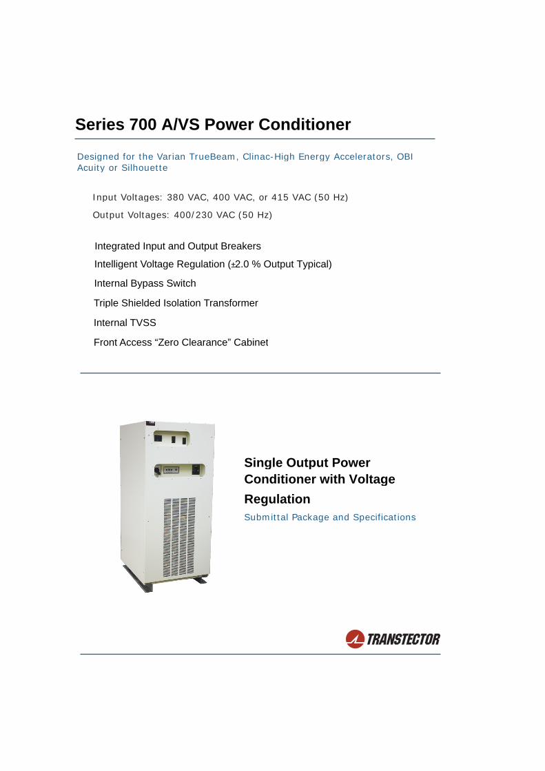
Series 700 A/VS Power Conditioner
Designed for the Varian TrueBeam, Clinac-High Energy Accelerators, OBIAcuity or Silhouette
Input Voltages: 380 VAC, 400 VAC, or 415 VAC (50 Hz)
Output Voltages: 400/230 VAC (50 Hz)
Integrated Input and Output Breakers
Intelligent Voltage Regulation (±2.0 % Output Typical)
Internal Bypass Switch
Triple Shielded Isolation Transformer
Internal TVSS
Front Access “Zero Clearance” Cabinet
Single Output Power Conditioner with Voltage Regulation Submittal Package and Specifications
A&E Specs/Submittal Package 2
TRANSTECTOR SERIES 700A/VS
Specifications for Single Output 50 Hz Power Conditioner, designed for Varian TrueBeam™, Clinac™-High Energy Linear Accelerators, OBI™ and Silhouette™.
1.0 SCOPEThis specification covers the electrical characteristics of the power conditioner with voltage regulation which provides clean,stable power to the connected load.
2.0 GENERALThe Power Line Conditioner consists of a front access power cabinet incorporating an all copper, multiple tapped, triple shield isolation/regulation transformer. The ultra low output impedance of the transformer in conjunction with the electrostatic shields assures precision hospital grade performance with excellent noise and transient attenuation. Independently controlled inverse parallel electronic switches for each of the 7 taps per phase provide tight regulation over a wide input range. Linear devices are used for line synchronization to prevent phase shift errors normally associated with simple CT zero current crossing acquisition. The microprocessor control accurately selects the correct tap to provide line voltage regulation of ±2.0 % typical, correcting for voltage disturbances within one cycle. Digital processing technique provides fast and accurate regulation without output voltage over or undershoots.
2.01 MODEL NUMBERSMODEL INPUT VOLTAGE OUTPUT VOLTAGE FREQUENCY
Model Input Voltage Output Voltages
8QSW- 50 K -700A/VS 400/230 VAC 50 Hz
8RSW- 50 K -700A/VS 400/230 VAC 50 Hz
8FSW- 50 K -700A/VS 415 VAC nominal input 400/230 VAC 50 Hz
2.1 AGENCIES
2.1.1 STANDARDSThe systems shall be designed in accordance with:
American National Standards Institute
Institute of Electrical and Electronic Engineers
National Electric Code (NEC)
National Fire Protection Association (NFPA Article 70)
Underwriters Laboratories (UL) 1449, 1012
CE Certification Requirements
FCC Article 15, Section J, Class A
ISO 9001
|/v
380 VAC nominal input
400 VAC nominal input
3
2.1.1 LISTINGSThe system shall be listed to UL standard UL1012
The system shall comply to: FCC Article 15, Section J, Class A and ANSI C62.14(electromagnetic compatibility)
The system shall be CE certified
3.0 DYNAMIC ELECTRICAL CHARACTERISTICS
3.1 OPERATING VOLTAGE AND OUTPUTSThe input voltage shall be 380 VAC, 400 VAC or 415 VAC, Delta, three phase, 50 Hz. The standard transformer design shall be capable of accepting one (1) of the three (3) input voltages: 380 VAC, 400 VAC or 415 VAC. Each unit will be pre-wired at the factory to accommodate the selected nominal input voltage. The input voltage can be changed in the field to accommodate any one of the three nominal input voltages.
3.2 LINE VOLTAGE REGULATION.Nominal Input Line Voltage +10 % to –15 %
Output Line Voltage Regulation ±2.0 % typical
The design of the system shall indicate that with an input voltage of -10 % of nominal, increasing the load to 1000 % shall cause the output voltage to fall no lower than -6 %.
3.3 OUTPUT VOLTAGEOutput voltage shall be 400/230 VAC 3 Phase 4 wire WYE.
3.4 OUTPUT CONNECTIONSAn 90 A three (3) pole circuit breaker is provided for the 400/230 VAC output. The Transtector surge suppressor will also have a dedicated circuit breaker or fuses.
3.5 INPUT/OUTPUT WIRINGInput wiring sizes:380 VAC #4 AWG to 350 KCMIL (25 mm2 to 150 mm2)400 VAC #4 AWG to 350 KCMIL (25 mm2 to 150 mm2)415 VAC #4 AWG to 350 KCMIL (25 mm2 to 150 mm2)
Output wiring sizes:400/230 VAC 80 A breaker #14 AWG to 1/0 (2.5 mm2 to 50 mm2)
The ILSCO TA-2/0 terminal allows wire sizes from #14 to 2/0 (2.5 mm2 to 50 mm2) to be connected to the ground.
1402-016
A&E Specs/Submittal Package 4
3.6 RESPONSE TIME
Response time is less than 1/2 cycle.
3.7 CORRECTION TIMEThe output voltage is corrected within 1 cycle.
3.8 LOAD REGULATION
The output is maintained to within 2 % of nominal or less, from no load to full load.
3.9 IMPEDANCE
Output impedance shall be less than 1.95 %
3.10 OPERATING FREQUENCY
50 Hertz ±3 Hertz
3.11 HARMONIC DISTORTIONLess than 1 % THD added to the output waveform under any dynamic linear loading conditions presented to the line regulator.
3.12 TURN-ON CHARACTERISTICSWhen energized the voltage overshoot is 5 % or less of the nominal voltage for less than 1 cycle.
3.13 OVERLOAD RATING200 % for ten seconds.1000 % for one cycle.
3.14 NOISE ATTENUATIONCommon mode noise attenuation is typically 140 dB or greater.Transverse mode noise attenuation is 3 dB down at 1000 Hertz, 40 dB down per decade to below 50 dB with a resistive load.
3.15 AUDIBLE NOISENot to exceed 55 dB measured @ 1 meter.
3.16 EFFICIENCYEfficiency shall be > 96.5 % typical at full load, continuous KVA rating. Excitation losses shall be less than 1.5 % of kVA rating.
3.17 HEAT OUTPUTNominal: 1000 W (3,410 BTU)Maximum: 2000 W (6,820 BTU)
3.18 POWER FACTORInput power factor shall be greater than .95 with a resistive load and reflect no triplen harmonics to the utility under non-linear loads.
|
5
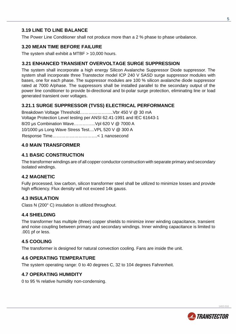
3.19 LINE TO LINE BALANCEThe Power Line Conditioner shall not produce more than a 2 % phase to phase unbalance.
3.20 MEAN TIME BEFORE FAILUREThe system shall exhibit a MTBF > 10,000 hours.
3.21 ENHANCED TRANSIENT OVERVOLTAGE SURGE SUPPRESSIONThe system shall incorporate a high energy Silicon Avalanche Suppressor Diode suppressor. The system shall incorporate three Transtector model ICP 240 V SASD surge suppressor modules with bases, one for each phase. The suppressor modules are 100 % silicon avalanche diode suppressor rated at 7000 A/phase. The suppressors shall be installed parallel to the secondary output of the power line conditioner to provide bi-directional and bi-polar surge protection, eliminating line or load generated transient over voltages.
3.21.1 SURGE SUPPRESSOR (TVSS) ELECTRICAL PERFORMANCEBreakdown Voltage Threshold…………………..Vbr 450 V @ 30 mAVoltage Protection Level testing per ANSI 62.41-1991 and IEC 61643-18/20 μs Combination Wave…………...Vpl 620 V @ 7000 A10/1000 μs Long Wave Stress Test....VPL 520 V @ 300 AResponse Time………………………….< 1 nanosecond
4.0 MAIN TRANSFORMER
4.1 BASIC CONSTRUCTIONThe transformer windings are of all copper conductor construction with separate primary and secondary isolated windings.
4.2 MAGNETICFully processed, low carbon, silicon transformer steel shall be utilized to minimize losses and provide high efficiency. Flux density will not exceed 14k gauss.
4.3 INSULATIONClass N (200° C) insulation is utilized throughout.
4.4 SHIELDINGThe transformer has multiple (three) copper shields to minimize inner winding capacitance, transient and noise coupling between primary and secondary windings. Inner winding capacitance is limited to .001 pf or less.
4.5 COOLINGThe transformer is designed for natural convection cooling. Fans are inside the unit.
4.6 OPERATING TEMPERATUREThe system operating range: 0 to 40 degrees C, 32 to 104 degrees Fahrenheit.
4.7 OPERATING HUMIDITY0 to 95 % relative humidity non-condensing.
1402-016

A&E Specs/Submittal Package 6
5.0 MAIN INPUT BREAKERA main input molded case thermal magnetic circuit breaker, rated at 175 As, is furnished as an integral part of the unit. The input breaker is appropriately sized to accommodate the 110K(I) rating and the input voltages of either 380, 400 or 415 VAC.
6.0 BY-PASS SWITCHA manually operated rotary bypass switch provides bypassing of the SCR controlled voltage regulator portion of the Power Line Conditioner. The Power Line Conditioner can be operated in either the on-line or bypassed mode with one turn of the switch. The transformer and surge suppression circuitry remains in the circuit when in the bypass mode. In bypass, Output #1 and Output #2 will be connected to the 400/230 VAC nominal tap, three (3) phase 4 wire WYE. The bypass switch is located on the front of the unit.
7.0 MONITORING
7.1 ALERT LIGHTAn indicator light shall annunciate that the output has been disabled by one of the following conditions:(1) Transformer over-temperature(2) SCR thermal over-temperature
7.2 INDICATING LAMPSOutput “ON” indicating lamps shall be provided for each phase.
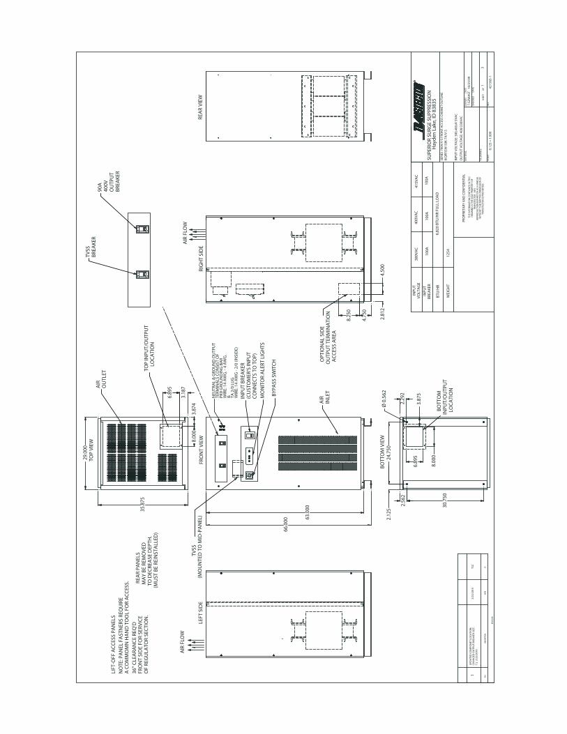
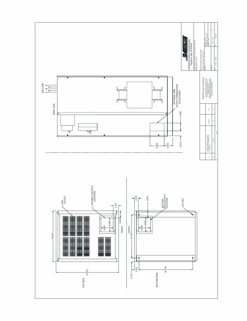
8.0 CABINET
8.1 TERMINATIONInput and output terminations shall be front access. Input terminations shall be made directly to the main input circuit breaker and the input ground terminal provided. Output terminations shall be made directly to the output circuit breaker and neutral & ground copper bus provided.
8.2 VENTILATIONVentilation originates from the front of the cabinet, exiting through the top.
8.3 MOBILITYThe Power Line Conditioner cabinets are equipped with angle iron supports that allow for transport by pallet jack or fork lift. These can be used for mounting unit to the floor in seismic zones.
8.4 ACCESSIBILITYThe Power Line Conditioner will have front access. Access to all wiring inputs, outputs, bypass and breakers will be accessible through the front access panels. The back of the unit may be set next to a wall without impeding access. It will also incorporate with lift off side panels.
8.5 WEIGHTUnit weight: Approximately 1254 lbs (568.8 kg)
8.6 DIMENSIONS73.6 cm X 91.12 cm X 167.64 cm 29" W X 35.875" D X 66" H
|/v
7
9.0 CONTROLSThe control portion of the cabinet containing the circuit boards and connection to the semi-conductor devices is separate from the transformer section and apart from the input and output power connections.
10.0 WARRANTYUnits shall include a comprehensive warranty for the two years, covering all parts and workmanship.
11.0 SERVICETranstector shall provide immediate phone support/consultation and if possible, same day parts shipment. (Contact must be prior to 12:00 PM PST). Consult factory for other services.
FOR ASSISTANCE CALL +1 208.762.6112 (8am-5pm Pacific Time)
AFTER HOURS CALL +1 208.755.2072
12.0 CONTACTRick Ribbeck Phone: +1 208.762.6112 or 1.800.882.9110 extension 6112Transtector Systems Cell: +1 208.755.207210701 Airport Dr. Fax: +1 208.762.6133Hayden Lake ID 83835 USA Email: [email protected]
1402-016
A&E Specs/Submittal Package 8
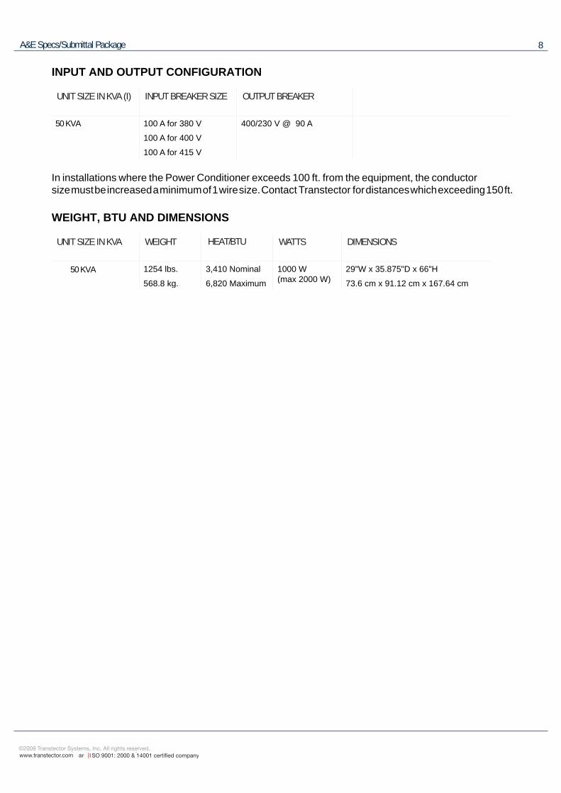
INPUT AND OUTPUT CONFIGURATION
UNIT SIZE IN KVA (I) INPUT BREAKER SIZE OUTPUT BREAKER
50 KVA 100 A for 380 V 400/230 V @ 90 A
100 A for 400 V
100 A for 415 V
In installations where the Power Conditioner exceeds 100 ft. from the equipment, the conductor size must be increased a minimum of 1 wire size. Contact Transtector for distances which exceeding 150 ft.
WEIGHT, BTU AND DIMENSIONS
UNIT SIZE IN KVA WEIGHT HEAT/BTU WATTS DIMENSIONS
50 KVA 1254 lbs. 3,410 Nominal 1000 W 29"W x 35.875"D x 66"H(max 2000 W)568.8 kg. 6,820 Maximum 73.6 cm x 91.12 cm x 167.64 cm
|
9
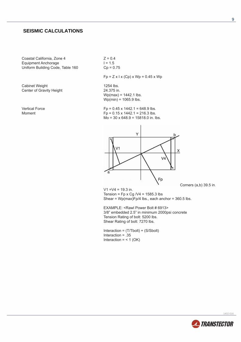
SEISMIC CALCULATIONS
1402-016
29.0
00
35.8
75
6.89
5
3.18
7
8.00
03.
874
8.00
0
6.89
5
2.29
22.
562
30.7
50
Ø 0
.562
2.12
524
.750
3.87
5
8.25
0
4.75
0
2.81
24.
500
66.0
00 63.0
00
1254
100A
100A
100A
415V
AC
400V
AC
380V
AC
6,82
0 B
TU/H
R FU
LL L
OA
D
INPU
TV
OLT
AG
E
INPU
TB
REA
KER
BTU
/HR
WEI
GH
T
BRE
AK
ERTV
SS
BRE
AK
ERO
UTP
UT
400V
90A
LEFT
SID
ERE
AR
VIE
W
OF
REG
ULA
TOR
SEC
TIO
N.
FRO
NT
SID
E FO
R SE
RVIC
E36
" C
LEA
RAN
CE
REQ
'D
A C
OM
MO
MN
HA
ND
TO
OL
FOR
AC
CES
S.N
OTE
: PA
NEL
FA
STN
ERS
REQ
UIR
E
LIFT
-OFF
AC
CES
S PA
NEL
S
T.S.
2/2
3/20
10C
HA
NG
ED O
UTP
UT
BRE
AK
ER S
IZE.
UPD
ATE
D C
OM
PON
ET L
OC
ATI
ON
,1
2/23
/201
0TS
Z
TOP
VIE
W
OU
TLET
AIR
L
OC
ATI
ON
TOP
INPU
T/O
UTP
UT
(MU
ST B
E RE
INST
ALL
ED)
TO
DEC
REA
SE D
EPTH
.
MA
Y B
E RE
MO
VED
R
EAR
PAN
ELS
LO
CA
TIO
NIN
PUT/
OU
TPU
T
BO
TTO
M
BO
TTO
M V
IEW
WIR
E: 1
4 A
WG
- 2/
0 (IN
SID
E)TA
2/0
LU
G&W
IRE:
14
AW
G. -
4 A
WG
.PK
9 G
ROU
ND
ING
BA
RTE
RMIN
ALS
CO
NSI
ST O
FN
EUTR
AL
& G
ROU
ND
OU
TPU
T
AIR
FLO
WA
IR F
LOW
RIG
HT
SID
E
AC
CES
S A
REA
OU
TPU
T TE
RMIN
ATI
ON
OPT
ION
AL
SID
E
FRO
NT
VIE
W
INLE
TA
IRCO
NN
ECTS
TO
TO
P)(C
UST
OM
ER'S
INPU
TIN
PUT
BRE
AK
ER
MO
NIT
OR
ALE
RT L
IGH
TS
BY
PASS
SW
ITC
H
(MO
UN
TED
TO
MID
-PA
NEL
)
T
VSS
OU
TPU
T V
OLT
AG
E: 4
00/2
30V
AC
INPU
T V
OLT
AG
E: 3
80,4
00,4
15V
AC
8(Q
RF)S
W-5
0K-7
A/V
-S
T.SZ
WA
ST
10/2
1/09
.
3
SERI
ES 7
00A
/V-S
FRO
NT
AC
CES
S C
AB
INET
OU
TLIN
E
Hay
den
Lak
e, ID
838
35SU
PERI
OR
SURG
E SU
PPRE
SSIO
N
R
0.12
5 =
1.0
00
1
.
.MA
TERI
AL
SCA
LE
TOLE
RAN
CE
SHEE
T
O
F
NO
.
CH
ECK
ED
D
ATE
DRA
WN
D
ATE
4215
65-1
PRO
PRIE
TARY
AN
D C
ON
FID
ENTI
AL
THE
INFO
RMA
TIO
N C
ON
TAIN
ED IN
TH
ISD
RAW
ING
IS T
HE
SOLE
PRO
PERT
Y O
FTR
AN
STEC
TOR.
AN
Y RE
PRO
DU
CTI
ON
IN P
ART
OR
AS
A W
HO
LEW
ITH
OU
T TH
E W
RITT
EN P
ERM
ISSI
ON
OF
TRA
NST
ECTO
R IS
PRO
HIB
ITED
.BY
DATE
DESC
RIPT
ION
REV.
REVI
SIONS
8.25
0
4.75
0
2.81
24.
500
8.00
0
6.89
5
2.29
22.
562
30.7
50
2.12
5
3.87
5
24.7
50
Ø 0
.562
29.0
00
35.8
75
6.89
5
3.18
7
3.87
4
8.00
0
AIR
FLO
W
RIG
HT
SID
E AC
CES
S A
REA
OU
TPU
T TE
RMIN
ATI
ON
OPT
ION
AL
SID
E
LO
CA
TIO
NIN
PUT/
OU
TPU
T
BO
TTO
M
BO
TTO
M V
IEW
TOP
VIE
W
L
OC
ATI
ON
TOP
INPU
T/O
UTP
UT
OU
TLET
AIR
FRO
NT
FRO
NT
TSZ
2/23
/201
0T.
S. 2
/23/
2010
CH
AN
GED
OU
TPU
T B
REA
KER
SIZ
E.U
PDA
TED
CO
MPO
NET
LO
CA
TIO
N,
1
OU
TPU
T V
OLT
AG
E: 4
00/2
30V
AC
INPU
T V
OLT
AG
E: 3
80,4
00,4
15V
AC
8(Q
RF)S
W-5
0K-7
A/V
-S
T.SZ
WA
ST
10/2
1/09
.
3
SERI
ES 7
00A
/V-S
FRO
NT
AC
CES
S C
AB
INET
OU
TLIN
E
Hay
den
Lak
e, ID
838
35SU
PERI
OR
SURG
E SU
PPRE
SSIO
N
R
0.12
5 =
1.0
00
.
.MA
TERI
AL
SCA
LE
TOLE
RAN
CE
SHEE
T
O
F
NO
.
CH
ECK
ED
D
ATE
DRA
WN
D
ATE
2
4215
65-1
REVI
SIONS
REV.
DESC
RIPT
ION
DATE
BY
PRO
PRIE
TARY
AN
D C
ON
FID
ENTI
AL
THE
INFO
RMA
TIO
N C
ON
TAIN
ED IN
TH
ISD
RAW
ING
IS T
HE
SOLE
PRO
PERT
Y O
FTR
AN
STEC
TOR.
AN
Y RE
PRO
DU
CTI
ON
IN P
ART
OR
AS
A W
HO
LEW
ITH
OU
T TH
E W
RITT
EN P
ERM
ISSI
ON
OF
TRA
NST
ECTO
R IS
PRO
HIB
ITED
.

TSZ
2/23
/201
0
UPD
ATE
D C
OM
PON
ET L
OC
ATI
ON
,C
HA
NG
ED O
UTP
UT
BRE
AK
ER S
IZE.
T.S.
2/2
3/20
101
TOP
VIE
W
FRO
NT
REV.
DESC
RIPT
ION
DATE
BY
4215
65-1
SERI
ES 7
00A
/V-S
FRO
NT
AC
CES
S C
AB
INET
OU
TLIN
E
Hay
den
Lak
e, ID
838
35SU
PERI
OR
SURG
E SU
PPRE
SSIO
N
R
8(Q
RF)S
W-5
0K-7
A/V
-S
.
3
0.12
5 =
1.0
00
.
.MA
TERI
AL
SCA
LE
TOLE
RAN
CE
SHEE
T
O
F
NO
.
CH
ECK
ED
D
ATE
DRA
WN
D
ATE
3
T.SZ
WA
ST 1
0/21
/09
INPU
T V
OLT
AG
E: 3
80,4
00,4
15V
AC
OU
TPU
T V
OLT
AG
E: 4
00/2
30V
AC
PRO
PRIE
TARY
AN
D C
ON
FID
ENTI
AL
THE
INFO
RMA
TIO
N C
ON
TAIN
ED IN
TH
ISD
RAW
ING
IS T
HE
SOLE
PRO
PERT
Y O
FTR
AN
STEC
TOR.
AN
Y RE
PRO
DU
CTI
ON
IN P
ART
OR
AS
A W
HO
LEW
ITH
OU
T TH
E W
RITT
EN P
ERM
ISSI
ON
OF
TRA
NST
ECTO
R IS
PRO
HIB
ITED
.


