
Singapore LandXML Mapping
and Structure Technical Paper for Singapore Land Authority, Version 1.4.0
Author: Curt Wilkinson. Seaconis Incorporated, California USA © 2017.
Created: 11 Oct, 2014
Last Revision: 11 Oct, 2017

SG LandXML Mapping and Structure 1.4 Technical Paper
Seaconis Inc. P a g e | 2
Contents
1 Introduction ........................................................................................................... 6
1.1 Purpose ............................................................................................................. 6
1.2 Abbreviations ..................................................................................................... 6
1.3 Audience ............................................................................................................ 6
1.4 Using this document .......................................................................................... 7
2 File Definition – Element Trees .............................................................................. 10
3 Elements and attributes ......................................................................................... 13
3.1 XML Prolog ........................................................................................................ 13
3.2 LandXML ........................................................................................................... 13
3.3 Units .................................................................................................................. 14
3.4 Metric ................................................................................................................. 14
3.5 CoordinateSystem ............................................................................................. 15
3.6 Application ......................................................................................................... 16
3.7 FeatureDictionary ............................................................................................... 16
3.8 DocFileRef ......................................................................................................... 17
3.9 CgPoints ............................................................................................................ 17
3.10 CgPoint .............................................................................................................. 18
3.11 Monuments ........................................................................................................ 18
3.12 Monument .......................................................................................................... 19
3.13 Parcels ............................................................................................................... 19
3.14 Parcel ................................................................................................................ 20
3.15 LocationAddress ................................................................................................ 22
3.16 ComplexName ................................................................................................... 22
3.17 RoadName ......................................................................................................... 23
3.18 AddressPoint ..................................................................................................... 23
3.19 Center ................................................................................................................ 24
3.20 CoordGeom ....................................................................................................... 25
3.21 Line .................................................................................................................... 26
3.22 Curve ................................................................................................................. 27
3.23 IrregularLine ....................................................................................................... 28
3.24 Start ................................................................................................................... 29
3.25 End .................................................................................................................... 29
3.26 PntList2D ........................................................................................................... 30
3.27 PntList3D ........................................................................................................... 31
3.28 VolumeGeom ..................................................................................................... 32
3.29 PlanFeatures ..................................................................................................... 32
3.30 PlanFeature ....................................................................................................... 33
3.31 Survey ............................................................................................................... 33
3.32 SurveyHeader .................................................................................................... 34
3.33 AdministrativeArea ............................................................................................. 35
3.34 PurposeOfSurvey ............................................................................................... 36
3.35 AdministrativeDate ............................................................................................. 36
3.36 Annotation .......................................................................................................... 37
3.37 SurveyorCertificate ............................................................................................ 38
3.38 Personnel ........................................................................................................... 39

SG LandXML Mapping and Structure 1.4 Technical Paper
Seaconis Inc. P a g e | 3
3.39 FieldNote ........................................................................................................... 39
3.40 ObservationGroup .............................................................................................. 40
3.41 ReducedObservation ......................................................................................... 41
3.42 Backsight ........................................................................................................... 42
3.43 BacksightPoint ................................................................................................... 43
3.44 InstrumentSetup ................................................................................................. 44
3.45 InstrumentPoint .................................................................................................. 44
3.46 Feature .............................................................................................................. 45
3.47 Property ............................................................................................................. 45
3.48 Amendment ....................................................................................................... 45
3.49 AmendmentItem ................................................................................................. 46
4 SG Specific Objects ............................................................................................... 48
4.1 Transformation ................................................................................................... 49
4.1.1 Parameters ..................................................................................................... 50
4.1.2 Residuals ....................................................................................................... 50
4.1.3 Residual ......................................................................................................... 51
4.1.4 Misclosure ...................................................................................................... 52
4.1.5 Misclose ......................................................................................................... 52
4.2 AdjustedLines .................................................................................................... 53
4.3 EDM ................................................................................................................... 53
4.3.1 Certificate ....................................................................................................... 54
4.3.2 Hardware ........................................................................................................ 55
4.3.3 ResidualSeries ............................................................................................... 56
4.3.4 Constants ....................................................................................................... 57
4.3.5 Precisions ....................................................................................................... 58
4.4 Occupational Details .......................................................................................... 59
4.4.1 Introduction ..................................................................................................... 59
4.4.2 Occupations ................................................................................................... 59
4.4.3 Occupation ..................................................................................................... 59
4.4.4 Occupation Properties .................................................................................... 61
4.4.5 Encroachments .............................................................................................. 61
4.4.6 Encroachment ................................................................................................ 62
4.4.7 Encroachment Properties ............................................................................... 63
4.5 Levelling............................................................................................................. 64
5 Complex Structures and Scenarios ....................................................................... 66
5.1 Parcels ............................................................................................................... 66
5.1.1 Parcel ............................................................................................................. 66
5.1.2 Parcel Class ................................................................................................... 67
5.1.3 Parcel Lineage ............................................................................................... 68
5.1.4 Physical Relationship ..................................................................................... 71
5.1.5 State Reserve ................................................................................................. 72
5.1.6 Balance Lot .................................................................................................... 73
5.1.7 Area Class and Description ............................................................................ 73
5.1.8 Old Format Lot Numbers ................................................................................ 73
5.1.9 Survey Type ................................................................................................... 73
5.2 Voids .................................................................................................................. 74
5.2.1 Parcels ........................................................................................................... 74

SG LandXML Mapping and Structure 1.4 Technical Paper
Seaconis Inc. P a g e | 4
5.2.2 Name Convention ........................................................................................... 74
5.2.3 Attributes ........................................................................................................ 74
5.2.4 Land Lot Void ................................................................................................. 74
5.3 Airspace and Subterranean Lots ........................................................................ 75
5.3.1 Airspace Lot Boundaries ................................................................................. 75
5.3.2 Subterranean Boundaries ............................................................................... 75
5.4 Part Lots ............................................................................................................ 76
5.5 SG Modified ICSM Structuring Spatial Elements ................................................ 77
5.6 Linking Observations to CgPoints ...................................................................... 78
5.7 Horizontal Control .............................................................................................. 79
5.7.1 Referenced in Surveys ................................................................................... 79
5.7.2 Detailed HCP Model ....................................................................................... 80
5.7.3 Validation Transfers ........................................................................................ 81
5.8 Vertical Control .................................................................................................. 82
5.8.1 Referenced in Survey ..................................................................................... 83
5.8.2 Detailed VCP Model ....................................................................................... 83
5.8.3 Validation Transfers ........................................................................................ 86
5.9 Addresses .......................................................................................................... 86
5.10 Associated Documents ...................................................................................... 88
5.11 Amendments ...................................................................................................... 88
5.11.1 Strikethrough method ..................................................................................... 88
5.12 Reference Plan Areas ........................................................................................ 89
5.13 Alteration of Survey District boundary (MKTS) ................................................... 90
5.14 Elevations .......................................................................................................... 91
6 Strata Plan Structures ........................................................................................... 92
6.1 STP Properties................................................................................................... 92
6.2 CPST Properties ................................................................................................ 93
6.3 Use of Parcel Element ....................................................................................... 93
6.4 The Third Dimension .......................................................................................... 94
6.5 Building .............................................................................................................. 94
6.5.1 Land Lot ......................................................................................................... 94
6.5.2 Address .......................................................................................................... 94
6.5.3 Elevations ....................................................................................................... 95
6.5.4 Example ......................................................................................................... 95
6.6 Level .................................................................................................................. 96
6.6.1 Attributes ........................................................................................................ 96
6.6.2 Name .............................................................................................................. 96
6.6.3 Coordinate Geometry ..................................................................................... 96
6.6.4 Elevation References ..................................................................................... 97
6.6.5 Occupation References .................................................................................. 97
6.7 Typical Storey .................................................................................................... 98
6.7.1 Attributes ........................................................................................................ 98
6.7.2 Virtual Parcels ................................................................................................ 98
6.7.3 Level Values ................................................................................................... 99
6.7.4 Parcel Values ................................................................................................. 99
6.7.5 Typical Lot ...................................................................................................... 100
6.7.6 Example of a Typical Storey ........................................................................... 101

SG LandXML Mapping and Structure 1.4 Technical Paper
Seaconis Inc. P a g e | 5
6.8 Strata Lots ......................................................................................................... 102
6.8.1 Attributes ........................................................................................................ 102
6.8.2 Name Convention ........................................................................................... 102
6.8.3 Area and Volume ............................................................................................ 102
6.8.4 Coordinate Geometry ..................................................................................... 103
6.8.5 Strata Lot Addresses ...................................................................................... 103
6.8.6 Measured Dimensions .................................................................................... 103
6.8.7 Relationships to Other Parcels ....................................................................... 104
6.8.8 Example ......................................................................................................... 104
6.9 Accessory Lots................................................................................................... 104
6.9.1 Attributes ........................................................................................................ 104
6.9.2 Name Convention ........................................................................................... 104
6.9.3 Area and Volume ............................................................................................ 105
6.9.4 Coordinate Geometry ..................................................................................... 105
6.9.5 Relationship to Strata Lot(s) ........................................................................... 105
6.9.6 Example ......................................................................................................... 105
6.10 Common Properties ........................................................................................... 106
6.10.1 Attributes ........................................................................................................ 106
6.10.2 Name Convention ........................................................................................... 106
6.10.3 Area and Volume ............................................................................................ 106
6.10.4 Coordinate Geometry ..................................................................................... 106
6.10.5 Example ......................................................................................................... 106
6.11 Void Areas and Spaces ...................................................................................... 107
6.11.1 Attributes ........................................................................................................ 107
6.11.2 Name Convention ........................................................................................... 107
6.11.3 Coordinate Geometry ..................................................................................... 107
6.11.4 Example ......................................................................................................... 107
7 Enumerations ........................................................................................................ 108
7.1 Primitive Data Types .......................................................................................... 108
7.2 LandXML Enumerated Types ............................................................................. 108
7.3 ICSM Jurisdiction Based Enumerated Types ..................................................... 110
7.4 SG Enumerated Types ....................................................................................... 111
8 Appendix A – Non-CSMS Ancillary Files ............................................................... 118
8.1 Permits Permission and Addresses .................................................................... 118
8.2 Files Produced During Submission Processing .................................................. 119
8.3 Surveyor Prepared Files .................................................................................... 119
8.4 Sketches ............................................................................................................ 120
9 Appendix B – PurposeOfSurvey Enumeration Encoding ....................................... 121
Works Cited 125
SG LandXML Mapping and Structure 1.4 Technical Paper
Seaconis Inc. P a g e | 6
1 Introduction
LandXML is the designated survey data transfer platform for the CSMS project and ensuing
production systems. The LandXML standard is further enhanced by the ICSM protocols.
This document specifies the elements that are required for submissions to SLA as part of the
future CSMS system. This Singapore protocol is both a subset and extension of the ICSM
LandXML specification (also known as the ICSM ePlan Protocol).
This document was initially derived from ePlan Protocol, LandXML Mapping, Version 2.1.2
ICSM, 2011. It has been significantly altered and extended thereafter. However, Section 3
still retains much of the structure and content of the original document.
1.1 Purpose
This document specifies the requirements for the construction of a digital plan for submission
to SLA. Its primary purpose is to define the SG LandXML schema for use by CSMS teams
developing the new systems. Secondarily, it is intended for use by survey software vendors
and surveyors to assist them in the development of Land XML functionality within their
software and practices.
1.2 Abbreviations
CIF Cadastral Information File (SLA intends to rename).
CPS Control Points System
CSMS Cadastral Survey Management System
ICSM Intergovernmental Committee on Surveying and Mapping
ISO International Standards Organisation
LADM ISO Land Administration Data Model, a.k.a. ISO 19152
LandXML XML schema for survey and construction
LX LandXML
SG Singapore
SGDRM Singapore Data Reference Model
SGLX Singapore LandXML
SLA Singapore Land Authority
SGCDM SG Cadastral Data Model and ISO LADM Profile, sister document
XML Extensible Markup Language
1.3 Audience
The audience for this document includes:
Singapore Land Authority and its contractors involved in the CSMS project and other projects implementing survey data transfer.
Future SLA staff and contractors who are maintaining or modifying the SLA LandXML standards and subsequent implementations.
The ICSM.
SG LandXML Mapping and Structure 1.4 Technical Paper
Seaconis Inc. P a g e | 7
Third party commercial software developers.
1.4 Using this document
This document’s structure is derived from similar ICSM documents (ICSM, 2011 and 2010).
It differs in that it combines what are often two or three different ICSM source documents
into one. This facilitated the development of the SG specification; it incorporates the
mapping of SG objects to the ICSM LX model, as well as sections discussing the structural
manipulation of LX to achieve specific SG requirements.
Section 1 contains background information on this document, its intended purposes and
references to other necessary information.
Section 2 provides a list of the XML elements that are used for plans being prepared for
submissions to SLA. The elements appear in the order that they appear in the LandXML
schema.
Section 3 is the main reference section of the document as it maps survey data to LandXML
elements. The section describes each element and its attributes in detail. Elements are
presented in the order that they appear in the LandXML schema, and each element's child
and parent elements are provided along with an example of use.
In this document, tables are used to assist the formatting and reference clarity of diverse
information. Most table attribution is relatively self-explanatory; however, the following have
special meaning:
Cardinality specifies how many child elements of a particular type an element must
have, e.g.:
0 - * means zero or more (i.e. the child is optional)
1 means exactly one
1 - * means at least one and possibly more
Type specifies the data type of an attribute. The type can be an XML base type such
as "string", or custom type that is defined in the schema. Types used by the Protocol
are listed as follows:
Base – a raw value type, e.g. "string".
LandXML Enumerations – an enumerated type defined in the LandXML Schema, e.g. "stateType".
Jurisdictional Enumerations – an enumerated type defined by the NSW enumerations schema, e.g. "parcelClass". These are defined as skeleton types in the LandXML schema that are extended by the jurisdictional enumerations.
Custom Jurisdictional Enumerations – defined as a base type in LandXML but with a custom enumeration type specified by a jurisdictional enumerations schema. For example, the horizontalDatumType – string is the type defined by LandXML. horizontalDatumType is the custom enumerated type specified by jurisdictional enumeration schemas with enumerated values. Fields must only contain values from this enumerations list.
SG LandXML Mapping and Structure 1.4 Technical Paper
Seaconis Inc. P a g e | 8
Other Defined Types – explicitly defined in as a type in LandXML but the underlying type is a base type. These are not extended in the jurisdictional schemas. The underlying LandXML base type is used.
For information on all the “type” definitions used by the ePlan Protocol, including LXML
and SG specific enumerated types, please refer to Chapter 5 in this document
Required specifies whether an attribute is:
- Required (R)—the attribute must be used when the element is used and must have a value that is not an empty string. e.g. Parcel elements must have a name attribute.
- Conditionally Required (CR)—the attribute must be used if some condition is met. e.g. CoordinateSystem element must have a desc if the plan is on MM orientation. The value will be the deposited plan to which the survey has been orientated
- Optional (O)—the attribute may be used e.g. Amendment elements have an optional comments attribute
NB: elements and attributes that are specified as optional in the ICSM specification may be required in this Singapore specification
Section 4 presents complex objects not defined in LandXML or ICSM yet required for Singapore. The section specifies LandXML structural requirements that are to be used in the construction of a submission.
SGLX heavily uses the Features and Properties approach (hereafter just called properties) to customize LX. This is the only allowed approach other than where an LX enumeration is not fixed. If an SGLX object is completely properties implemented, it will be in this section. If SG objects are encoded through LX elements, even if heavily modified by the properties approach, it will be in section 5.
Section 5 presents complex scenarios and special handling for Singapore. The section specifies LandXML structural requirements that are to be used in the construction of a CIF where necessary to handle scenarios that require LandXML to be structured in a certain way to correctly capture the data.
Section 6 presents a discussion of 3D encoding.
Section 7 presents a listing of enumerations.
Appendix A presents a listing and discussion of the existing ancillary files submitted by surveyors to SLA. This appendix may be removed in the future.
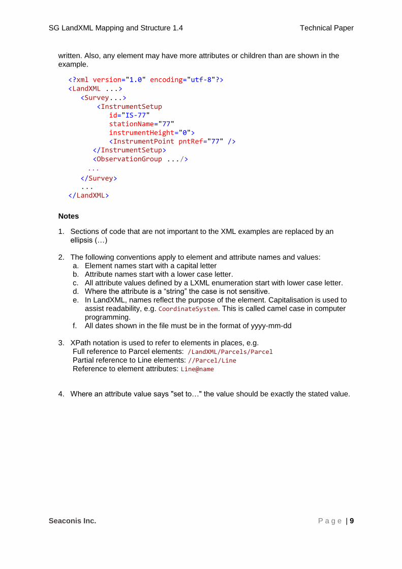
In All sections, XML code will be presented as incomplete XML examples
XML examples use two formatting styles in this document. The first is valid XML code, where brown texts are elements, red attributes and blue values. Many XML examples show ellipses which replace code unimportant to the example and the XML is not valid as
SG LandXML Mapping and Structure 1.4 Technical Paper
Seaconis Inc. P a g e | 9
written. Also, any element may have more attributes or children than are shown in the example.
<?xml version="1.0" encoding="utf-8"?> <LandXML ...> <Survey...> <InstrumentSetup id="IS-77" stationName="77" instrumentHeight="0"> <InstrumentPoint pntRef="77" /> </InstrumentSetup> <ObservationGroup .../>
...
</Survey> ... </LandXML>
Notes
1. Sections of code that are not important to the XML examples are replaced by an ellipsis (…)
2. The following conventions apply to element and attribute names and values:
a. Element names start with a capital letter b. Attribute names start with a lower case letter. c. All attribute values defined by a LXML enumeration start with lower case letter. d. Where the attribute is a “string” the case is not sensitive. e. In LandXML, names reflect the purpose of the element. Capitalisation is used to
assist readability, e.g. CoordinateSystem. This is called camel case in computer programming.
f. All dates shown in the file must be in the format of yyyy-mm-dd
3. XPath notation is used to refer to elements in places, e.g. Full reference to Parcel elements: /LandXML/Parcels/Parcel Partial reference to Line elements: //Parcel/Line Reference to element attributes: Line@name
4. Where an attribute value says "set to…" the value should be exactly the stated value.

SG LandXML Mapping and Structure 1.4 Technical Paper
Seaconis Inc. P a g e | 10
2 File Definition – Element Trees
A LandXML file for use in the SG CSMS will contain the LandXML elements that are shown
in the diagrams below in the order they appear in the LandXML schema. Note that SG also
has a number of custom XML objects encoded using the Feature/Property approach to
extending LandXML.
Figure 1 SG LandXML Elements Used
LandXML
XML Prologue
Application
CoordinateSystem
Units Metric
DocFileRef
CgPointCgPoints
FeatureDictionary
Property
Parcel (reference)Parcels
Parcels Parcel
LocationAddress
ComplexName
RoadName
AdministrativeArea
AddressPoint
VolumeGeom CoordGeom
CoordGeomElements
CoordGeom
Feature Property
AmendmentItemAmendment
Center
Monuments Monument
Feature

SG LandXML Mapping and Structure 1.4 Technical Paper
Seaconis Inc. P a g e | 11
Figure 2 SG LandXML Elements Used (Continued)
SurveyHeader
CoordGeomElements
LandXML (cont)
PlanFeatures PlanFeature CoordGeom
FieldNote
Feature Property
PurposeOfSurvey
AdministrativeDate
AdministrativeArea
Personnel
SurveyorCertification
Annotation
FieldNote
Feature Property
Survey
ObservationGroup ReducedObservation
Backsight Backsite Point
InstrumentPointInstrumentSetup
SG LandXML Mapping and Structure 1.4 Technical Paper
Seaconis Inc. P a g e | 12
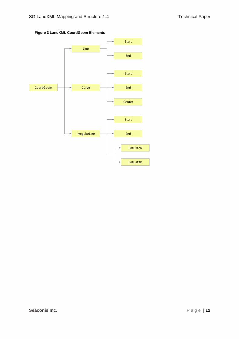
Figure 3 LandXML CoordGeom Elements
CoordGeom
Line
Curve
IrregularLine
Start
End
Start
End
Center
Start
End
PntList2D
PntList3D
SG LandXML Mapping and Structure 1.4 Technical Paper
Seaconis Inc. P a g e | 13
3 Elements and attributes
The file will contain the following data elements:
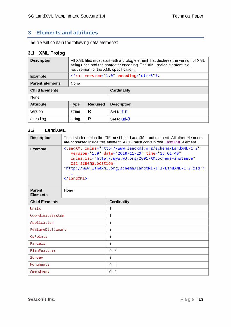
3.1 XML Prolog
Description All XML files must start with a prolog element that declares the version of XML being used and the character encoding. The XML prolog element is a requirement of the XML specification,
Example <?xml version="1.0" encoding="utf-8"?>
Parent Elements None
Child Elements Cardinality
None
Attribute Type Required Description
version string R Set to 1.0
encoding string R Set to utf-8
3.2 LandXML
Description The first element in the CIF must be a LandXML root element. All other elements are contained inside this element. A CIF must contain one LandXML element.
Example <LandXML xmlns="http://www.landxml.org/schema/LandXML-1.2" version="1.0" date="2010-11-29" time="15:01:49" xmlns:xsi="http://www.w3.org/2001/XMLSchema-instance" xsi:schemaLocation= "http://www.landxml.org/schema/LandXML-1.2/LandXML-1.2.xsd"> … </LandXML>
Parent Elements
None
Child Elements Cardinality
Units 1
CoordinateSystem 1
Application 1
FeatureDictionary 1
CgPoints 1
Parcels 1
PlanFeatures 0 - *
Survey 1
Monuments 0 - 1
Amendment 0 - *
SG LandXML Mapping and Structure 1.4 Technical Paper
Seaconis Inc. P a g e | 14
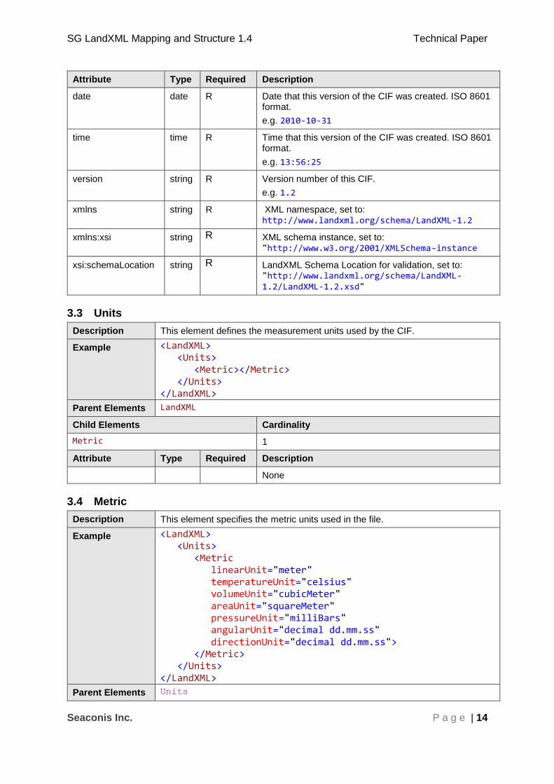
Attribute Type Required Description
date date R Date that this version of the CIF was created. ISO 8601 format.
e.g. 2010-10-31
time time R Time that this version of the CIF was created. ISO 8601 format.
e.g. 13:56:25
version string R Version number of this CIF.
e.g. 1.2
xmlns string R XML namespace, set to: http://www.landxml.org/schema/LandXML-1.2
xmlns:xsi string R XML schema instance, set to: "http://www.w3.org/2001/XMLSchema-instance
xsi:schemaLocation string R LandXML Schema Location for validation, set to: "http://www.landxml.org/schema/LandXML-1.2/LandXML-1.2.xsd"
3.3 Units
Description This element defines the measurement units used by the CIF.
Example <LandXML> <Units> <Metric></Metric> </Units> </LandXML>
Parent Elements LandXML
Child Elements Cardinality
Metric 1
Attribute Type Required Description
None
3.4 Metric
Description This element specifies the metric units used in the file.
Example <LandXML> <Units> <Metric linearUnit="meter" temperatureUnit="celsius" volumeUnit="cubicMeter" areaUnit="squareMeter" pressureUnit="milliBars" angularUnit="decimal dd.mm.ss" directionUnit="decimal dd.mm.ss"> </Metric> </Units> </LandXML>
Parent Elements Units

SG LandXML Mapping and Structure 1.4 Technical Paper
Seaconis Inc. P a g e | 15
Child Elements Cardinality
None
Attribute Type Required Description
linearUnit metLinear R Set to "meter"
temperatureUnit metTemperature R Set to "celsius"
volumeUnit metVolume R Set to "cubicMeter"
areaUnit metArea R Set to "squareMeter"
pressureUnit metPressure R Set to "milliBars"
angularUnit angularType CR Set to "decimal dd.mm.ss" angular
values expressed in "decimal dd.mm.ss" units have the numeric format "45.3025" representing 45 degrees 30 minutes and 25 seconds. Both the minutes and seconds must be two characters with a numeric range between 00 to 60.
directionUnit angularType R Set to "decimal dd.mm.ss"
3.5 CoordinateSystem
Description The CoordinateSystem element defines the coordinate system used for
CgPoint coordinates in the CIF.
Example <LandXML> <CoordinateSystem desc="only if not SVY21, otherwise do not write” datum="SVY21" horizontalDatum="SVY21" verticalDatum="SHD"> </CoordinateSystem> </LandXML>
Parent Elements LandXML
Child Elements Cardinality
None
Attribute Type Required Description
desc string CR Defines the orientation of the survey, if not SVY21.
datum String(surveyDatumType) R SVY21 datum
horizontalDatum string (horizDatumType) R Datum of CgPoint horizontal
coordinates.
verticalDatum string (vertDatumType) CR Required if 3D points are used. Singapore Height Datum (SHD).

SG LandXML Mapping and Structure 1.4 Technical Paper
Seaconis Inc. P a g e | 16
3.6 Application
Description The Application element records information about the surveying software
application used to create the CIF.
Example <LandXML> <Application name="PlanTest" manufacturer="Seaconis Inc." version="2.0.7" manufacturerURL="www.seaconis.com" /> </LandXML>
Parent Elements LandXML
Child Elements Cardinality
None
Attribute Type Required Description
name string R The name of the application that created the CIF.
e.g. MyApp
manufacturer string O The name of the manufacturer of the application.
version string R The version of the application
e.g. 2.1.3
manufacturerURL string O The web site or URL of the manufacturer.
3.7 FeatureDictionary
Description The FeatureDictionary element specifies the version of the reference data and
enumerations list used when building the SG LandXML. Following ICSM, only one feature dictionary is used to refer to the collection of jurisdictionally specific schemas, see ICSM document “ePlan Protocol – Schema Architecture”. For example, local government reference data lists may be changed more frequently than state level jurisdictional enumerations list and therefore are versioned as a separate feature dictionary.
In SG, we may use the FeatureDictionary more generally as needed. If we
do, we will need to ensure that the ICSM model is not broken.
Example <FeatureDictionary name="ReferenceDataContext" version="SG-01"> <DocFileRef name="referencedata.xml" location="url ...referencedata.xml"/> </FeatureDictionary>
Parent Elements LandXML
Child Elements Cardinality
DocFileRef 0 - *
Attribute Type Required Description
name string R The name of the feature dictionary. Names are specified at the jurisdictional level based on the organisation of jurisdictional enumeration and reference data lists.
version string R The version of the feature dictionary used for this CIF.

SG LandXML Mapping and Structure 1.4 Technical Paper
Seaconis Inc. P a g e | 17
3.8 DocFileRef
Description The DocFileRef element is a reference to any external document file containing
related information for the associated element. In SG, it is used for several purposes.
1) It is used to record the details about the FeatureDictionary including the
names, locations and attributes of the files that comprise the feature dictionary.
2) Associated files are referenced in DocFileRef elements contained in a Feature@name = “RefDocs” under the SurveyHeader.
3) As a container for image and supporting documents for HCP and VCP.
Example <DocFileRef name="SLA/LPB/40.49.4-V6" location="./referencedata.xml"> </DocFileRef>
Parent Feature, FeatureDictionary
Child Elements Cardinality
None
Attribute Type Required Description
name string R File name
location anyURI R URI of file. This may be a location on the jurisdiction
web site.
fileType fileType
Type
O The type of file. For example, “ReferencePlan” to
identify the reference plan for the survey submission.
fileFormat string O The format of the file.
3.9 CgPoints
Description The CgPoints element is a container for all the CgPoint elements in the file.
Example <LandXML...> ... <CgPoints> <CgPoint ...="">...</CgPoint> <CgPoint ...="">...</CgPoint> ... </CgPoints> ... </LandXML>
Parent Elements LandXML
Child Elements Cardinality
CgPoint 1 - *
Attribute Type Required Description
none

SG LandXML Mapping and Structure 1.4 Technical Paper
Seaconis Inc. P a g e | 18
3.10 CgPoint
Description CgPoint may represent boundary points, traverse points, reference marks,
permanent survey marks and various administrative points. Elements link to CgPoints to attach survey information.
The datum for these coordinates is specified by LandXML:CoordinateSystem.
Example <CgPoints> <CgPoint name="3" desc="final" code="L01" pntSurv="traverse"> 29568.716 30286.225 </CgPoint> ... <CgPoint name="24" desc="final" code="L01" pntSurv="control"> 29568.716 30286.225 101.5 </CgPoint> </CgPoints>
Element Content Coordinate values for the point. Two dimensional coordinates are a coordinate pair of the Northing followed by Easting. Three dimensional coordinates are a coordinate triplet: Northing, Easting and Height. Coordinates are separated by a single space.
Parent Elements CgPoints
Child Elements Cardinality
None
Attribute Type Required Description
name string R Unique (to file) identifier for the point. Also called station number in most cases.
desc approvalStateType R SLA enumeration related to process state of approval.
pntSurv survPntType R The point type, LandXML enumeration.
code methodType R SLA enumeration of survey method to define the point.
oID string O The universally unique identifier (UUID) in the SG cadastre. It is a large integer number that identifies existing points, and is exported from the CSMS database at the beginning of survey projects.
3.11 Monuments
Description The Monuments element is a container for Monument elements. Feature
elements are referenced by Monument elements via featureRef to access
additional properties not envisioned by LandXML.
Example <LandXML...> ... <Monuments> ... <Monument/> ... <Feature/> ... </Monuments> ... </LandXML>

SG LandXML Mapping and Structure 1.4 Technical Paper
Seaconis Inc. P a g e | 19
Parent Elements LandXML
Child Elements Cardinality
Monument 1 - *
Feature 0 - *
Attribute Type Required Description
none
3.12 Monument
Description The Monument element holds information on Survey Marks placed or referenced
in the SLA surveys. A Monument is always linked to a CgPoint using the pntRef
attribute, which in Singapore is the station number. The CgPoint defines the
survey mark's position and identification. Multiple Monuments can be linked to the
same CgPoint. For example, there may be a nail in concrete for the corner and
a reference to a brick wall at the same point.
This element defines the physical attributes of all survey marks on the plan including boundary, reference and survey control marks.
A Monument may reference Feature elements under the Monuments element to
encode complex situations, like vertical control witness marks. See the structural discussion sections.
Example <Monuments> <Monument name="27" pntRef="33" featureRef="2" type="NL" state="found"> </Monument> </Monuments>
Parent Elements Monuments
Child Elements Cardinality
Attribute Type Required Description
name string R SG use to hold ISN number, unique number otherwise. Prefix of “SM” for horizontal control, and “VCP” for vertical control.
pntRef pointNameRef R Reference to the name attribute of the linked
CgPoint, for Singapore this is the station
number.
featureRef featureNameRef O Reference to a Feature element. Used in vertical control encoding.
type monumentType R SLA jurisdictional list of monument types.
state monumentState R SLA jurisdictional list of states. (found, refixed, new…)
desc String O Can be used to describe the location or for other purposes.
3.13 Parcels
Description The Parcels element is a container for individual Parcel elements. Parcels
containers can be nested within Parcel elements to capture parcel relationships.

SG LandXML Mapping and Structure 1.4 Technical Paper
Seaconis Inc. P a g e | 20
Example <LandXML...> ... <Parcels> <Parcel.../> ... </Parcels> ... </LandXML>
Parent Elements LandXML
Child Elements Cardinality
Parcel 1 - *
Attribute Type Required Description
None
3.14 Parcel
Description The Parcel element provides a basic unit to describe a spatial area. A
Parcel element can contain a nested Parcels element that has Parcel
child elements. This is how we will reference the internal (island) lots. There are fewer required attributes for these "sub" parcels, generally only requiring a name and pclRef.
Coordinate geometry used to define the lines that form each parcel are stipulated to be written in a counter-clockwise sequence in SG LandXML. This is opposite the current ICSM convention and the ESRI convention, but in agreement with ISO, OGC and the much larger computer graphics community and software products.
Parcel may have many Feature/Property sets. See structural discussions.
Example <LandXML…> ... <Parcels> <Parcel name="TS30-00385M" desc="CP1234, CP2345" area="1245.8" class="final" parcelType ="land" parcelFormat="Standard"> <CoordGeom> ... </CoordGeom> <Parcels> <Parcel/> </Parcels> </Parcel> </Parcels> ... </LandXML>
Parent Elements Parcels

SG LandXML Mapping and Structure 1.4 Technical Paper
Seaconis Inc. P a g e | 21
Child Elements Cardinality
Center 0 - 1
CoordGeom 0 - 1
VolumeGeom 0-1
Parcels (island parcels only pclRef) 0 - *
LocationAddress 0 - *
Feature 0 - *
Attribute Type Required Description
name string R Concatenation of these several identifiers
District is either MK (Mukim) or TS (Town Subdivision) (char (2))
District number (number (2))
Lot number (integer (5))
Check digit (char (1))
Lot numbers can be for proposed or existing lots. Lot numbers are issued by SLA. For allocation, lot names can follow a different pattern (PLOT<alphanumeric>).
desc string CR Formatted string of plan numbers. These are the plans that show the parcel.
area double CR The legal area. Required for new lots.
Must be in units as specified in Units
element
class parcelClass R In the context of the survey, this describes the role of a parcel.
parcelFormat parcelFormat R Describes the physical format of a parcel.
volume double O Mandatory where parcelFormat format is
extruded or 3D.
parcelType parcelTypeType R Describes the general category of the parcel.
useOfParcel useOfParcelType CR Describes the use of the parcel, in SG is used for “vacant” lots.
pclRef parcelNameRef CR Reference to a parcel by name. Used for island parcels, accessory parcels, and other associations between parcels.
buildingNo string CR The block number (house) of the building.
buildingLevelNo string CR The level (storey) where lot is located.
SG LandXML Mapping and Structure 1.4 Technical Paper
Seaconis Inc. P a g e | 22
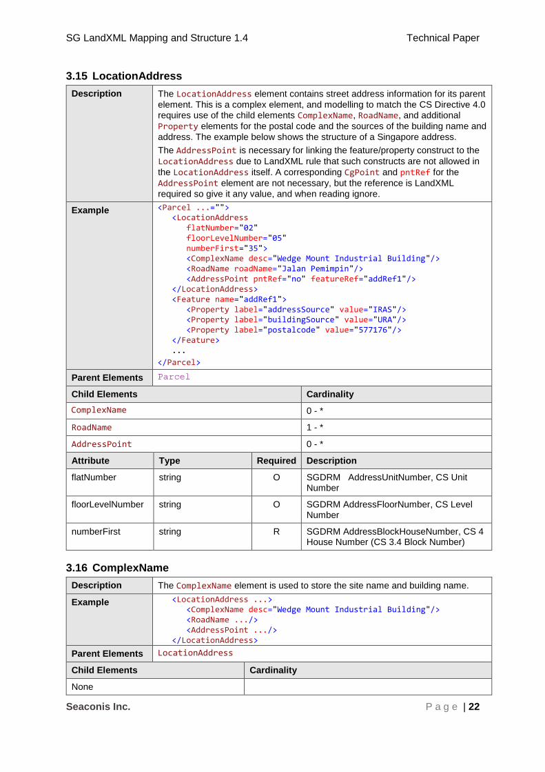
3.15 LocationAddress
Description The LocationAddress element contains street address information for its parent
element. This is a complex element, and modelling to match the CS Directive 4.0 requires use of the child elements ComplexName, RoadName, and additional
Property elements for the postal code and the sources of the building name and
address. The example below shows the structure of a Singapore address.
The AddressPoint is necessary for linking the feature/property construct to the
LocationAddress due to LandXML rule that such constructs are not allowed in
the LocationAddress itself. A corresponding CgPoint and pntRef for the
AddressPoint element are not necessary, but the reference is LandXML
required so give it any value, and when reading ignore.
Example <Parcel ...=""> <LocationAddress flatNumber="02" floorLevelNumber="05" numberFirst="35"> <ComplexName desc="Wedge Mount Industrial Building"/> <RoadName roadName="Jalan Pemimpin"/> <AddressPoint pntRef="no" featureRef="addRef1"/> </LocationAddress> <Feature name="addRef1"> <Property label="addressSource" value="IRAS"/> <Property label="buildingSource" value="URA"/> <Property label="postalcode" value="577176"/> </Feature> ...
</Parcel>
Parent Elements Parcel
Child Elements Cardinality
ComplexName 0 - *
RoadName 1 - *
AddressPoint 0 - *
Attribute Type Required Description
flatNumber string O SGDRM AddressUnitNumber, CS Unit Number
floorLevelNumber string O SGDRM AddressFloorNumber, CS Level Number
numberFirst string R SGDRM AddressBlockHouseNumber, CS 4 House Number (CS 3.4 Block Number)
3.16 ComplexName
Description The ComplexName element is used to store the site name and building name.
Example <LocationAddress ...> <ComplexName desc="Wedge Mount Industrial Building"/> <RoadName .../> <AddressPoint .../> </LocationAddress>
Parent Elements LocationAddress
Child Elements Cardinality
None
SG LandXML Mapping and Structure 1.4 Technical Paper
Seaconis Inc. P a g e | 23
Attribute Type Required Description
desc string R SGDRM AddressBuildingName. CS 4 Building name. In LandXML, the site name, building name or other name.
priority Int R The priority of the ComplexName in relation to other
ComplexName (s) defined in the LocationAddress.
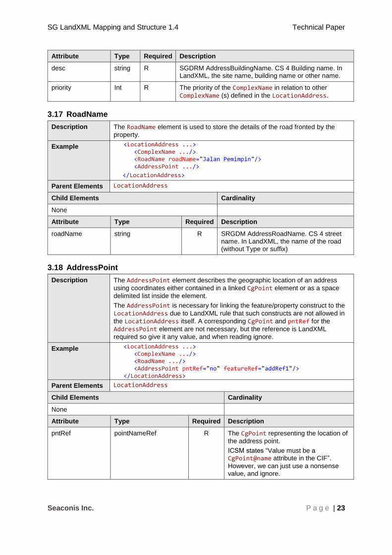
3.17 RoadName
Description The RoadName element is used to store the details of the road fronted by the
property.
Example <LocationAddress ...> <ComplexName .../> <RoadName roadName="Jalan Pemimpin"/> <AddressPoint .../>
</LocationAddress>
Parent Elements LocationAddress
Child Elements Cardinality
None
Attribute Type Required Description
roadName string R SRGDM AddressRoadName. CS 4 street name. In LandXML, the name of the road (without Type or suffix)
3.18 AddressPoint
Description The AddressPoint element describes the geographic location of an address
using coordinates either contained in a linked CgPoint element or as a space
delimited list inside the element.
The AddressPoint is necessary for linking the feature/property construct to the
LocationAddress due to LandXML rule that such constructs are not allowed in
the LocationAddress itself. A corresponding CgPoint and pntRef for the
AddressPoint element are not necessary, but the reference is LandXML
required so give it any value, and when reading ignore.
Example <LocationAddress ...> <ComplexName .../> <RoadName .../> <AddressPoint pntRef="no" featureRef="addRef1"/> </LocationAddress>
Parent Elements LocationAddress
Child Elements Cardinality
None
Attribute Type Required Description
pntRef pointNameRef R The CgPoint representing the location of
the address point.
ICSM states “Value must be a CgPoint@name attribute in the CIF”.
However, we can just use a nonsense value, and ignore.
SG LandXML Mapping and Structure 1.4 Technical Paper
Seaconis Inc. P a g e | 24
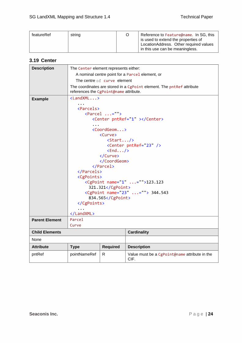
featureRef string O Reference to Feature@name. In SG, this
is used to extend the properties of LocationAddress. Other required values in this use can be meaningless.
3.19 Center
Description The Center element represents either:
A nominal centre point for a Parcel element, or
The centre of curve element
The coordinates are stored in a CgPoint element. The pntRef attribute
references the CgPoint@name attribute.
Example <LandXML...> ... <Parcels> <Parcel ...=""> <Center pntRef="1" ></Center> ... <CoordGeom...> <Curve> <Start.../> <Center pntRef="23" /> <End.../> </Curve> </CoordGeom> </Parcel> </Parcels> <CgPoints> <CgPoint name="1" ...="">123.123 321.321</CgPoint> <CgPoint name="23" ...=""> 344.543 834.565</CgPoint> </CgPoints> ... </LandXML>
Parent Element Parcel
Curve
Child Elements Cardinality
None
Attribute Type Required Description
pntRef pointNameRef R Value must be a CgPoint@name attribute in the
CIF.

SG LandXML Mapping and Structure 1.4 Technical Paper
Seaconis Inc. P a g e | 25
3.20 CoordGeom
Description The CoordGeom element is a container for the spatial components of its parent
element.
This section is used to define the lines that form each parcel in a counter-clockwise sequence. (This is opposite the current ICSM convention and the ESRI convention, but in agreement with a larger community of graphic and spatial software).
Example <LandXML...> ... <Parcels> <Parcel ...=""> <CoordGeom name="1"> <Line ...=""> <Start ...="" /> <End ...="" /> </Line> ... </CoordGeom> </Parcel> </Parcels> ... <PlanFeatures ...=""> <PlanFeature ...=""> <CoordGeom name="Wall2 " desc="" state="Retaining Wall"> <Line> <Start name="62" pntRef="62"/> <End pntRef="77"></End> </Line> <Line> <Start name="77" pntRef="77"/> <End pntRef="57"></End> </Line> ... </CoordGeom> </PlanFeature> </PlanFeatures> ... </LandXML>
Parent Elements Parcel
PlanFeature
Child Elements Cardinality
Line 0 - *
Curve 0 - *
IrregularLine 0 - *
Attribute Type Required Description
SG LandXML Mapping and Structure 1.4 Technical Paper
Seaconis Inc. P a g e | 26
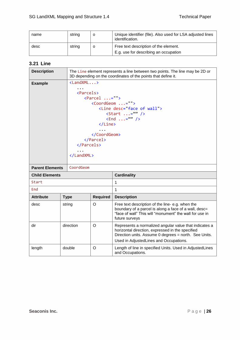
name string o Unique identifier (file). Also used for LSA adjusted lines identification.
desc string o Free text description of the element.
E.g. use for describing an occupation
3.21 Line
Description The Line element represents a line between two points. The line may be 2D or
3D depending on the coordinates of the points that define it.
Example <LandXML...> ... <Parcels> <Parcel ...=""> <CoordGeom ...=""> <Line desc="face of wall"> <Start ...=”” /> <End ...=”” /> </Line> ... </CoordGeom> </Parcel> </Parcels> ... </LandXML>
Parent Elements CoordGeom
Child Elements Cardinality
Start 1
End 1
Attribute Type Required Description
desc string O Free text description of the line- e.g. when the boundary of a parcel is along a face of a wall, desc= “face of wall” This will “monument” the wall for use in future surveys
dir direction O Represents a normalized angular value that indicates a horizontal direction, expressed in the specified Direction units. Assume 0 degrees = north. See Units.
Used in AdjustedLines and Occupations.
length double O Length of line in specified Units. Used in AdjustedLines and Occupations.

SG LandXML Mapping and Structure 1.4 Technical Paper
Seaconis Inc. P a g e | 27
3.22 Curve
Description A Curve is a specific type of regular line between two points. It is defined by its
start and end points, its radius, direction of rotation and centre point (i.e. radius point).
Example <LandXML...> ... <Parcels> <Parcel ...=""> <CoordGeom ...=""> <Curve radius="1" rot="cw"> <Start ...="" /> < Center ... /> < End... /> </Curve> </CoordGeom> </Parcel> </Parcels> ... </LandXML>
Parent Elements CoordGeom
Child Elements Cardinality
Start 1
End 1
Center 1
Attribute Type Required Description
radius double R The radius of the curve
rot clockwise R Direction from Start to End
Value will be “cw” (clockwise) or “ccw” (counter clockwise)

SG LandXML Mapping and Structure 1.4 Technical Paper
Seaconis Inc. P a g e | 28
3.23 IrregularLine
Description Irregular lines are used to capture non-surveyed lines (e.g. river boundary). ICSM requires a CgPoint as its start and finish point, whereas LandXML only
requires the use of the Start and End elements, which can contain either a
pntRef attribute, or coordinates. In Singapore, coordinates are used to start and
end occupation irregular lines. In all cases, a point list defines the line between the start and end points.
Example <LandXML...> ... <Parcels> <Parcel ...=""> <CoordGeom ...=""> <IrregularLine desc="bank of river" source=""> <Start ...="" /> <End ...="" /> <PntList2D ...=""/> </IrregularLine> </CoordGeom> </Parcel> </Parcels> ... </LandXML>
Parent Elements CoordGeom
Child Elements Cardinality
Start 1
End 1
PntList2D or PntList3D 1
Attribute Type Required Description
desc string O Free text description of the irregular line If the boundary is an irregular feature then the feature must be described e.g. "The Left Bank of the Darling River"
source string O The origin, if the line has been adopted from another source.
E.g. as in a previous CP
SG LandXML Mapping and Structure 1.4 Technical Paper
Seaconis Inc. P a g e | 29
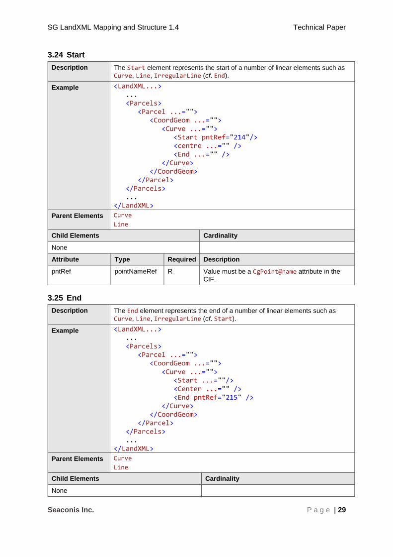
3.24 Start
Description The Start element represents the start of a number of linear elements such as
Curve, Line, IrregularLine (cf. End).
Example <LandXML...> ... <Parcels> <Parcel ...=""> <CoordGeom ...=""> <Curve ...=""> <Start pntRef="214"/> <centre ...="" /> <End ...="" /> </Curve> </CoordGeom> </Parcel> </Parcels> ... </LandXML>
Parent Elements Curve
Line
Child Elements Cardinality
None
Attribute Type Required Description
pntRef pointNameRef R Value must be a CgPoint@name attribute in the
CIF.
3.25 End
Description The End element represents the end of a number of linear elements such as
Curve, Line, IrregularLine (cf. Start).
Example <LandXML...> ... <Parcels> <Parcel ...=""> <CoordGeom ...=""> <Curve ...=""> <Start ...=""/> <Center ...="" /> <End pntRef="215" /> </Curve> </CoordGeom> </Parcel> </Parcels> ... </LandXML>
Parent Elements Curve
Line
Child Elements Cardinality
None

SG LandXML Mapping and Structure 1.4 Technical Paper
Seaconis Inc. P a g e | 30
Attribute Type Required Description
pntRef pointNameRef R Value must be a CgPoint@name attribute in the
CIF.
3.26 PntList2D
Description The PntList2D element is used with associated Start and End elements to
define a two dimensional line using a sequence of space separated (y, x) or (northing, easting) coordinate pairs that are the content of the element.
The first and last coordinate pair must be the same as the associated Start and
End points respectively (therefore the element must contain at least two
coordinate pairs).
Example <LandXML...> ... <Parcels> <Parcel ...=""> <CoordGeom ...=""> <IrregularLine ...=""> <Start ...=""/> <End ...=""/> <PntList2D> 11.11 22.22 ... 33.33 44.44/> </IrregularLine> </CoordGeom> </Parcel> </Parcels> ... </LandXML>
Element Content A space delimited list of coordinate values in Northing Easting pairing.
<PntList2D>N0 E0 N1 E1 ... Nn En</PntList2D>
Parent Elements IrregularLine
Child Elements Cardinality
None
Attribute Type Required Description
None
SG LandXML Mapping and Structure 1.4 Technical Paper
Seaconis Inc. P a g e | 31
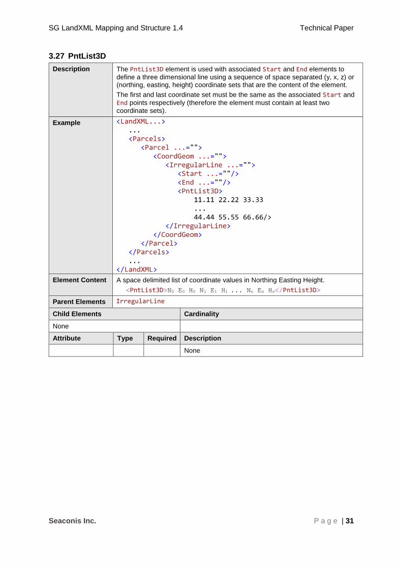
3.27 PntList3D
Description The PntList3D element is used with associated Start and End elements to
define a three dimensional line using a sequence of space separated (y, x, z) or (northing, easting, height) coordinate sets that are the content of the element.
The first and last coordinate set must be the same as the associated Start and
End points respectively (therefore the element must contain at least two
coordinate sets).
Example <LandXML...> ... <Parcels> <Parcel ...=""> <CoordGeom ...=""> <IrregularLine ...=""> <Start ...=""/> <End ...=""/> <PntList3D> 11.11 22.22 33.33 ... 44.44 55.55 66.66/> </IrregularLine> </CoordGeom> </Parcel> </Parcels> ... </LandXML>
Element Content A space delimited list of coordinate values in Northing Easting Height.
<PntList3D>N0 E0 H0 N1 E1 H1 ... Nn En Hn</PntList3D>
Parent Elements IrregularLine
Child Elements Cardinality
None
Attribute Type Required Description
None

SG LandXML Mapping and Structure 1.4 Technical Paper
Seaconis Inc. P a g e | 32
3.28 VolumeGeom
Description Defines the properties of a 3D Coordinate Geometry collection. LandXML and ICSM. SG use for 3D Volumetric definitions of Airspace, Subterranean, Strata and Accessory lots.
Example <LandXML...> ... <Parcels> <Parcel ...=""> <VolumeGeom name="" desc="" state="" oID=""> <CoordGeom ...="" /> <CoordGeom ...="" /> <CoordGeom ...="" /> <CoordGeom ...="" /> </VolumeGeom> </Parcel> </Parcels> ... </LandXML>
Parent Elements Parcel
Child Elements Cardinality
CoordGeom 4 - *
Attribute Type Required Description
name string O Unique identifier
desc string O Free text description of the element
state stateType O For use with amendments. LandXML enumeration.
oID string O Jurisdictional identifier
3.29 PlanFeatures
Description A container for PlanFeature elements. In SG, it is used for occupations,
encroachments and where required, additional miscellaneous cartographic elements.
Example <LandXML...> ... <PlanFeatures name="Occupations"> <PlanFeature.../> </PlanFeatures> <PlanFeatures name="Encroachments"> <PlanFeature.../> </PlanFeatures> ... </LandXML>
Parent Elements LandXML
SG LandXML Mapping and Structure 1.4 Technical Paper
Seaconis Inc. P a g e | 33
Child Elements Cardinality
PlanFeature 1 - *
Attribute Type Required Description
name string R Unique ePlan identifier in ICSM. Use “Adjusted” for element parent of adjusted lines, and “Occupations” for details. These are containers.
desc string O A description.
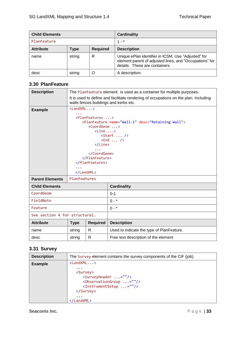
3.30 PlanFeature
Description The PlanFeature element is used as a container for multiple purposes.
It is used to define and facilitate rendering of occupations on the plan. Including walls fences buildings and kerbs etc.
Example <LandXML...> ... <PlanFeatures ...> <PlanFeature name="Wall-1" desc="Retaining Wall"> <CoordGeom ...> <Line ...> <Start ... /> <End ... /> </Line> ... </CoordGeom> </PlanFeature> </PlanFeatures> ...
</LandXML>
Parent Elements PlanFeatures
Child Elements Cardinality
CoordGeom 0-1
FieldNote 0 - *
Feature 0 - *
See section 4 for structural…
Attribute Type Required Description
name string R Used to indicate the type of PlanFeature.
desc string R Free text description of the element
3.31 Survey
Description The Survey element contains the survey components of the CIF (job).
Example <LandXML...> ... <Survey> <SurveyHeader ...=""/> <ObservationGroup ...=""/> <InstrumentSetup ...=""/> </Survey> ... </LandXML>
SG LandXML Mapping and Structure 1.4 Technical Paper
Seaconis Inc. P a g e | 34
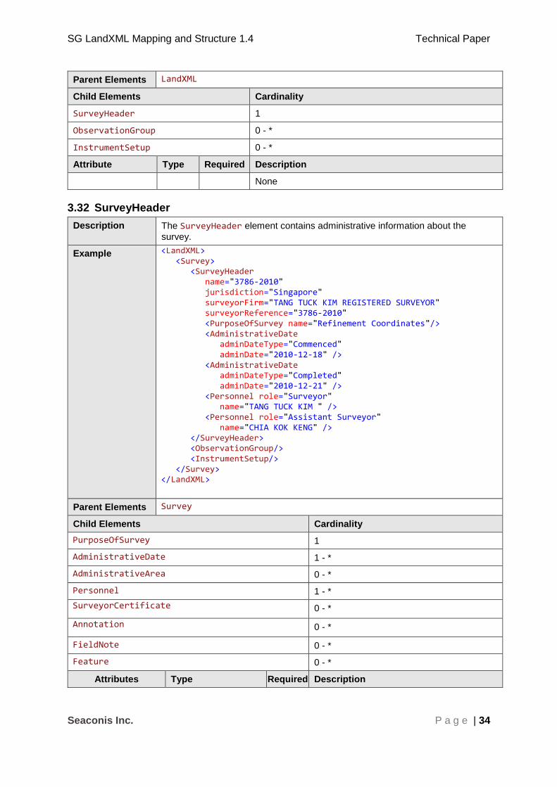
Parent Elements LandXML
Child Elements Cardinality
SurveyHeader 1
ObservationGroup 0 - *
InstrumentSetup 0 - *
Attribute Type Required Description
None
3.32 SurveyHeader
Description The SurveyHeader element contains administrative information about the
survey.
Example <LandXML> <Survey> <SurveyHeader name="3786-2010" jurisdiction="Singapore" surveyorFirm="TANG TUCK KIM REGISTERED SURVEYOR" surveyorReference="3786-2010" <PurposeOfSurvey name="Refinement Coordinates"/> <AdministrativeDate adminDateType="Commenced" adminDate="2010-12-18" /> <AdministrativeDate adminDateType="Completed" adminDate="2010-12-21" /> <Personnel role="Surveyor" name="TANG TUCK KIM " /> <Personnel role="Assistant Surveyor" name="CHIA KOK KENG" /> </SurveyHeader> <ObservationGroup/> <InstrumentSetup/> </Survey> </LandXML>
Parent Elements Survey
Child Elements Cardinality
PurposeOfSurvey 1
AdministrativeDate 1 - *
AdministrativeArea 0 - *
Personnel 1 - *
SurveyorCertificate 0 - *
Annotation 0 - *
FieldNote 0 - *
Feature 0 - *
Attributes Type Required Description
SG LandXML Mapping and Structure 1.4 Technical Paper
Seaconis Inc. P a g e | 35
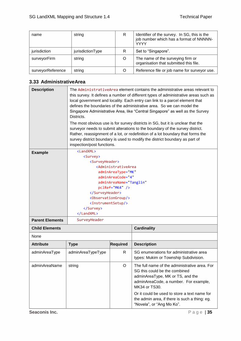
name string R Identifier of the survey. In SG, this is the job number which has a format of NNNNN-YYYY
jurisdiction jurisdictionType R Set to “Singapore”.
surveyorFirm string O The name of the surveying firm or organisation that submitted this file.
surveyorReference string O Reference file or job name for surveyor use.
3.33 AdministrativeArea
Description The AdministrativeArea element contains the administrative areas relevant to
this survey. It defines a number of different types of administrative areas such as
local government and locality. Each entry can link to a parcel element that
defines the boundaries of the administrative area. So we can model the
Singapore Administrative Area, like “Central Singapore” as well as the Survey
Districts.
The most obvious use is for survey districts in SG, but it is unclear that the
surveyor needs to submit alterations to the boundary of the survey district.
Rather, reassignment of a lot, or redefinition of a lot boundary that forms the
survey district boundary is used to modify the district boundary as part of
inspection/post functions.
Example <LandXML>
<Survey>
<SurveyHeader>
<AdministrativeArea
adminAreaType="MK"
adminAreaCode="4"
adminAreaName="Tanglin"
pclRef="MK4" />
</SurveyHeader>
<ObservationGroup/>
<InstrumentSetup/>
</Survey>
</LandXML>
Parent Elements SurveyHeader
Child Elements Cardinality
None
Attribute Type Required Description
adminAreaType adminAreaTypeType R SG enumerations for administrative area
types: Mukim or Township Subdivision.
adminAreaName string O The full name of the administrative area. For
SG this could be the combined
adminAreaType, MK or TS, and the
adminAreaCode, a number. For example,
MK34 or TS30.
Or it could be used to store a text name for
the admin area, if there is such a thing: eg.
“Novela”, or “Ang Mo Ko”.
SG LandXML Mapping and Structure 1.4 Technical Paper
Seaconis Inc. P a g e | 36
adminAreaCode string R The admin area number.
pclRef parcelNameRefs O A reference to the name of a parcel element
representing this administrative area. In the
cause of modelling for survey district
polygons, this would be the references to the
‘parcel’ spatial unit representing the survey
district boundary.
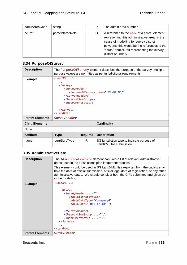
3.34 PurposeOfSurvey
Description The PurposeOfSurvey element describes the purpose of the survey. Multiple
purpose values are permitted as per jurisdictional requirements.
Example <LandXML...> ... <Survey> <SurveyHeader> <PurposeOfSurvey name="CPLNDALN"/> </SurveyHeader> <ObservationGroup/> <InstrumentSetup/> ... </Survey> </LandXML>
Parent Elements SurveyHeader
Child Elements Cardinality
None
Attribute Type Required Description
name purpSurvType R SG jurisdiction type to indicate purpose of LandXML file submission.
3.35 AdministrativeDate
Description The AdministrativeDate element captures a list of relevant administrative
dates used in the jurisdictions plan lodgement process.
This element could be used in SG LandXML files exported from the cadastre, to hold the date of official submission, official legal date of registration, or any other administrative dates. We should consider both the CIFs submitted and given out in the modelling.
Example <LandXML...> ... <Survey> <SurveyHeader ...=""> <AdministrativeDate adminDateType="Commenced" adminDate="2010-12-18" /> ... </SurveyHeader> <ObservationGroup ...=""/> <InstrumentSetup ...=""/> </Survey> ... </LandXML>
Parent Elements SurveyHeader

SG LandXML Mapping and Structure 1.4 Technical Paper
Seaconis Inc. P a g e | 37
Child Elements Cardinality
None
Attribute Type Required Description
adminDateType adminDateTypeType R Type of date. We can use this to record legal or processing dates.
adminDate xs:date R Date associated with the event defined in adminDateType. Format yyyy-mm-dd
3.36 Annotation
Description Annotation is a descriptive string use to describe an action on survey. The Annotation element is used in conjunction with the jurisdictional annotations schema. This element can be used for a number of purposes: cartographic annotation, specific legal text for certain parcel types, or for storing a list of plans used or referenced by a survey.
Example <SurveyHeader …="" > … <Annotation type="RoadLabel" name="Newton Road" desc=" 38240.710 30381.185 38240.588 30381.140 "/> <Annotation type="PlanNote" name="1. The common property extends to those parts indicated on the plans annexed hereto. " desc="33629.100 34631.591 33627.194 34621.774"/> <Annotation type="PlanNote" name="Legend" desc="33669.317 34618.715 33716.567 34627.785"/> <Annotation type="ParcelNote" name="remark1" desc="Allotted for Foreshore" pclRef="MK34-23456F"/> <Annotation type="AbuttalLine" name="" desc="33629.100 34631.591 33627.194 34621.774"/> <Annotation type="AbuttalLot" name="MK23-06354T" desc="33716.567 34627.785"/> <Annotation type="HouseNumber" name="45" desc="33669.317 34618.715"/> <Annotation type="OccupationNote" name="No details along boundary line" desc="33669.317 34618.715 33716.567 34627.785"/> <Annotation type="HWMNote" name="2.515m H.W.M." desc="33669.317 34618.715 33716.567 34627.785"/> … </SurveyHeader>

SG LandXML Mapping and Structure 1.4 Technical Paper
Seaconis Inc. P a g e | 38
Parent Elements SurveyHeader
Child Elements Cardinality
None
Attribute Type Required Description
type annotationType R Jurisdictional enumeration of annotations that can be used in SG.
name string R The annotation textual content.
desc string O Depending on the type, this could be textual content for longer descriptions, or it may be coordinates necessary for placing the annotation.
pclRef string CR Reference of the parcel to the ParcelNote. This attribute is used only by annotationType “ParcelNote”.
3.37 SurveyorCertificate
Description The SurveyorCertificate element is used in conjunction with the jurisdictional
certificates schema (see § 1.3 References - 3 ICSM, ePlan Protocol – Schema Architecture, version 2.0, 19 October, 2010). The text contained in textCertificate should conform to the layout specified in the jurisdiction's
certificates schema.
Example <LandXML> <Survey> <SurveyHeader> <SurveyorCertificate name="Cert1" certificateType="CP" textCertificate="I, Sean Tan, a surveyor registered under the Land Surveyors Act (Cap. 156), certify that this document has been prepared by me or under my immediate supervision, in accordance with the Boundaries and Survey Maps (Conduct of Cadastral Surveys) Rules 2005 (G.N. No. S 155/2005)." surveyDate=""/> </SurveyHeader> <ObservationGroup/> <InstrumentSetup/> </Survey> </LandXML>
Parent Elements SurveyHeader
Child Elements Cardinality
None
Attribute Type Required Description
name string R Unique identifier.
certificateType certificateTypeType R The jurisdictional enumeration of certificate type in SG.
textCertificate string R The text of the certificate information.
surveyDate Date O The date the survey was completed if applicable. Format yyyy-mm-dd

SG LandXML Mapping and Structure 1.4 Technical Paper
Seaconis Inc. P a g e | 39
3.38 Personnel
Description The Personnel element captures information about the personnel who
participated in the survey and the surveyor who endorsed the survey.
Example <LandXML> <Survey> <SurveyHeader> <Personnel name="Tang Tuck Kim" role="Surveyor" regNumber="006" /> <Personnel name="Sean Connery" role="Authorised Assistant" regNumber="0007" /> </SurveyHeader> <ObservationGroup/> <InstrumentSetup/> </Survey> </LandXML>
Parent Elements SurveyHeader
Child Elements Cardinality
None
Attribute Type Required Description
name string R Full name of the surveyor as registered.
role surveyorRoleType R The role the surveyor played in the survey.
regNumber string O Surveyor's board registration number
3.39 FieldNote
Description Notes are added as content of the FieldNote element. Plain text or any valid
XML structure may be placed inside this element. It is the responsibility of the jurisdiction to supply XML schemas or DTDs for the XML content of this element.
Example <LandXML...> ... <Survey> <SurveyHeader ...=""> <FieldNote>This is a field note.</FieldNote> </SurveyHeader> ... </Survey> ... </LandXML>
Parent Elements SurveyHeader, PlanFeature, ReducedObservation
Child Elements Cardinality
None (If custom XML is used, child elements of the custom XML will be shown.)

SG LandXML Mapping and Structure 1.4 Technical Paper
Seaconis Inc. P a g e | 40
Attribute Type Required Description
3.40 ObservationGroup
Description The ObservationGroup element is a container element for all types of
observation elements. Primarily in SG we will use it to hold traverses, Side-shots and observations. The stations are linked to the CgPoints by reference. The
example here is for a Main Loop traverse.
Example <LandXML ...> <Survey...> <ObservationGroup id="Main"> <Backsight .../> <ReducedObservation name="1" .../> <ReducedObservation name="2" .../> <ReducedObservation name="3" .../> . . . </ObservationGroup>
...
</Survey> ... </LandXML>
Parent Elements Survey
Child Elements Cardinality
ReducedObservation 1 - *
Backsight 1
Attribute Type Required Description
id ID R As LandXML allows multiple observation groups, each observation group has an “id”. ID value should be unique within the file. Must start with an alpha character and may not contain spaces.
SG use will be “Main”, Sub1”, “Sub2”, … “Observation1” … “SideShot1” …

SG LandXML Mapping and Structure 1.4 Technical Paper
Seaconis Inc. P a g e | 41
3.41 ReducedObservation
Description The ReducedObservation element contains a reduced horizontal measurement
being the bearing and distance. The measurement is related to CgPoint
elements using references to InstrumentSetup elements for the setupID and
targetSetupID attributes. (See InstrumentSetup) for details.)
Example <LandXML ...> <Survey...> <ObservationGroup id="Main"> <Backsight circle="270.0000" setupID="IS-2"> <BacksightPoint pntRef="1" /> </Backsight> <ReducedObservation name="1" equipmentUsed="NIKON NPL-632" purpose="traverse" horizDistance="81.762" azimuth="166.5331" setupID="IS-2" targetSetupID="IS-3" /> <ReducedObservation name="2" .../> <ReducedObservation name="3" .../> <ReducedObservation name="4" .../> . . . </ObservationGroup>
...
</Survey> ... </LandXML>
Parent Elements ObservationGroup
Child Elements Cardinality
FieldNote 0 - *
Attribute Type Required Description
name string R Unique identifier.
equipmentUsed equipmentType O JOB file does not match EDM to stations. Ignore for now.
purpose purposeType R LandXML enumeration, which describes the purpose of this observation in reference to the whole survey. Values include normal, check, backsight, foresight, traverse, etc. See LandXML Schema for complete list.
setupID IDREF R A reference to the InstrumentSetup
id that this measurement is made
from
targetSetupID IDREF R A reference to the InstrumentSetup
id that this measurement is made to
azimuth direction CR Bearing. Not required for calculated lines.

SG LandXML Mapping and Structure 1.4 Technical Paper
Seaconis Inc. P a g e | 42
horizDistance double R Horizontal distance
3.42 Backsight
Description A Backsight is a reading taken on a position of known coordinate(s). Since a
survey progresses from a point of known position to points of unknown position, a backsight is a reading looking "backward" along the line of progress
Example <LandXML ...> <Survey...> <ObservationGroup id="Main"> <Backsight circle="260.0000" setupID="IS-2"> <BacksightPoint name="-1" pntRef="23" /> </Backsight> <ReducedObservation name="1" .../> <ReducedObservation name="2" .../> <ReducedObservation name="3" .../> . . . </ObservationGroup>
...
</Survey> ... </LandXML>
Parent Elements ObservationGroup
Child Elements Cardinality
BacksightPoint 1
Attribute Type Required Description
azimuth angle R Could replace circle, as we use azimuth in SG, and circle just silly. But circle is required, so we will break validation if it is not used.
circle angle R LandXML required. Represents a normalized angular value in the specified Angular units. Assumes 0 degrees = east. We will use as if azimuth (angle from North).
setupID IDREF R A reference to the InstrumentSetup id that this
measurement is made from

SG LandXML Mapping and Structure 1.4 Technical Paper
Seaconis Inc. P a g e | 43
3.43 BacksightPoint
Description BacksightPoint is the target of a Backsight, a previously occupied known position.
Example <LandXML ...> <Survey...> <ObservationGroup id="Main"> <Backsight circle="260.0000" setupID="IS-2"> <BacksightPoint name="-1" pntRef="23" /> </Backsight> <ReducedObservation name="1" .../> <ReducedObservation name="2" .../> <ReducedObservation name="3" .../> . . . </ObservationGroup>
...
</Survey> ... </LandXML>
Parent Elements Backsight
Child Elements Cardinality
none
Attribute Type Required Description
name string R Our backsight is always another station, so we use the pntRef to indicate the station that is the target of the backsight. Since name is required by LandXML (through inheritance of PointType) we set as “-1” (and
ignore).
pntRef pointNameRef R Reference to the name attribute of the linked CgPoint.
So this the target point of the backsight.

SG LandXML Mapping and Structure 1.4 Technical Paper
Seaconis Inc. P a g e | 44
3.44 InstrumentSetup
Description The InstrumentSetup element links observation setup points to a CgPoint.
This is purely a structural requirement of LandXML to link observation start and end points to a physical location. See the example box for an explanation of this structure. See Linking Observations to CgPoints in Structural Discussions section for detailed description on use.
Example <LandXML ...> <Survey...> <InstrumentSetup id="IS-77" stationName="77" instrumentHeight="0"> <InstrumentPoint pntRef="77" /> </InstrumentSetup> <ObservationGroup .../>
...
</Survey> ...
</LandXML>
Parent Elements Survey
Child Elements Cardinality
InstrumentPoint 1
Attribute Type Required Description
id ID R ID value should be unique within the document.
Must start with an alpha character and may not
contain spaces.
stationName string R Set to the station name of the setup.
instrumentHeight double R Required by LandXML but optional for ICSM? Can be ignored if not needed. Set to “0”.
For SG, it is not currently submitted, so we can ignore.
3.45 InstrumentPoint
Description The InstrumentPoint element contains the reference to the CgPoint for the
InstrumentSetup.
Example See example for InstrumentSetup
Parent Elements InstrumentSetup
Child Elements Cardinality
None
Attribute Type Required Description
pntRef pointNameRef R Reference to the CgPoint for this
InstrumentPoint.

SG LandXML Mapping and Structure 1.4 Technical Paper
Seaconis Inc. P a g e | 45
3.46 Feature
Description Feature is used to include additional information that is not explicitly defined by
the LandXML schema. Feature may contain one or more Property,
DocFileRef or nested Feature elements.
Example <PlanFeature name="-" ... <Feature name="Thing"> <Property label="organisation" value="owner of…" /> <Property label="observer" value="name" /> <Property label="date" value="YYYY-MM-DD" /> </Feature> </PlanFeature>
Parent Elements LandXML and many other elements but not all.
Child Elements Cardinality
Property 0 - *
Feature 0 - *
DocFileRef 0 - *
Attribute Type Required Description
name string R Used to identify the object.
3.47 Property
Description Property is used to include additional information that is not explicitly defined by
the LandXML schema. Each Property element defines one piece of data.
Example <Feature name="occProps"> <Property label="code" value="column"/> <Property label="geometry" value="polygon"/> <Property label="pclRef" value="MK18-U12345A"/> </Feature>
Parent Elements Feature
Child Elements Cardinality
none
Attribute Type Required Description
label string R Used to identify the data
value string R Value of the data
3.48 Amendment
Description The Amendment element is used to record amendments made to the file. This is
a LandXML element.

SG LandXML Mapping and Structure 1.4 Technical Paper
Seaconis Inc. P a g e | 46
Example <LandXML...> ... <Amendment dealingNumber="CP12345" amendmentDate="2010-02-09" comments="Lot MK12-12345A added to plan"> <AmendmentItem elementName="Parcel" newName="MK12-12345A"/> </Amendment>
...
</Amendment>
... </LandXML>
Parent Elements LandXML
Child Elements Cardinality
AmendmentItem 1 - *
Attribute Type Required Description
dealingNumber string CR This could be the SLA amendment file number
amendmentDate date R The date that the amendment was made. Format yyyy-mm-dd
comments string R Description of the amendment - see example above
3.49 AmendmentItem
Description The AmendmentItem element contains information about individual
amendments. AmendmentItem elements require that the LandXML element being amended is uniquely identifiable in the file using its name attribute.
Therefore, AmendmentItem requires that every element in the file subject to an
amendment must be named uniquely across the entire file. AmendmentItem is
used primarily for the "strikeout" method where amendment history is tracked within the CIF rather than in a separate dataset. Specific requirements on this element can be found in section 2.4.1 of the ICSM LandXML Structural Requirements document.
Example <LandXML...> ... <Amendment ...=""> <AmendmentItem elementName="Monument" oldName="402" newName="709"/> </Amendment> ... </LandXML>
Parent Elements Amendment
Child Elements Cardinality
none
Attribute Type Required Description
elementName string R The name of the element being amended, e.g. if a ReducedObservation element is being
replaced then the value of elementName is
"ReducedObservation"
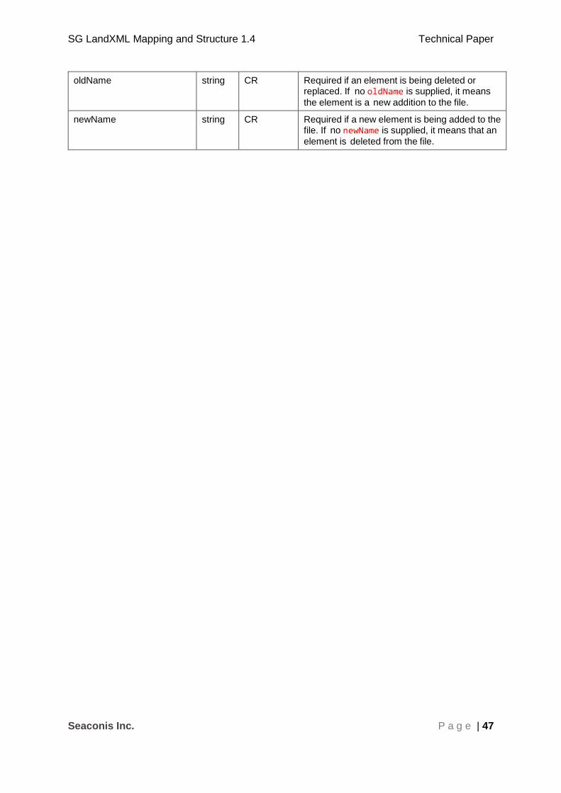
SG LandXML Mapping and Structure 1.4 Technical Paper
Seaconis Inc. P a g e | 47
oldName string CR Required if an element is being deleted or replaced. If no oldName is supplied, it means
the element is a new addition to the file.
newName string CR Required if a new element is being added to the file. If no newName is supplied, it means that an
element is deleted from the file.

SG LandXML Mapping and Structure 1.4 Technical Paper
Seaconis Inc. P a g e | 48
4 SG Specific Objects
Submissions to SLA include the reduced observations for traverse loops, observations and
side-shots. The also include the results of Least Squares Adjustment (LSA) and the
parameters of the LSA. There are two new survey objects: Misclose and Parameters. In
order to keep this all in a single group, separate from the survey observation groups under
Survey, we model them as Feature/Property structures under the SurveyHeader as they
apply at the survey level and they have no spatial data. Under plan features we have placed
a PlanFeature to hold the adjusted lines which could not be moved up to the SurveyHeader.

SG LandXML Mapping and Structure 1.4 Technical Paper
Seaconis Inc. P a g e | 49
4.1 Transformation
Description The Transformation properties and results are grouped under a Feature @Transformation element under SurveyHeader. In the sample below we show a larger than normal example so you can see how it works from the top level.
Example <SurveyHeader> ... <Feature name="Transformation"> <Feature name="Parameters"> <Property label="a1" value="0.836544" /> <Property label="b1" value="-0.547919" /> <Property label="a2" value="212.398250" /> <Property label="b2" value="-88.061250" /> </Feature> <Feature name="Residuals"> <Feature name="Residual"> <Property label="station" value="1" /> <Property label="northing" value="-0.001" /> <Property label="easting" value="0.002" /> </Feature> <Feature name="Residual"> <Property label="station" value="7" /> <Property label="northing" value="-0.001" /> <Property label="easting" value="0.000" /> </Feature> ... as many as control </Feature> <Feature name="Misclosure"> <Feature name="Misclose"> <Property label="refName" value="Main" /> <Property label="angularMisclose" value="-16" /> <Property label="miscloseRatio" value="1:65787" /> </Feature> <Feature name="Misclose"> <Property label="refName" value="Sub1" /> <Property label="angularMisclose " value="-20" /> <Property label="miscloseRatio " value="1:44876" /> </Feature> ... (same numbers as traverse loops) </Feature> </Feature> </SurveyHeader>
Parent Elements SurveyHeader
Child Elements Cardinality
Feature – name set to “Misclosure” 1
Feature – name set to “Parameters” 1
Feature – name set to “Residuals” 1
Attribute Type Required Description
name string R name = “Transformation” This identifies the Feature
as the container of the LSA results.

SG LandXML Mapping and Structure 1.4 Technical Paper
Seaconis Inc. P a g e | 50
4.1.1 Parameters
Description The transformation parameters are properties of a Feature with the specific
name value of “Parameters”. The four properties are label value pairs, and their labels must be “a1”, “a2”,” b1” and “b2” the values are numeric entered as string.
Example <SurveyHeader> ... <Feature name="Transformation"> <Feature name="Parameters"> <Property label="a1" value="0.836544" /> <Property label="b1" value="-0.547919" /> <Property label="a2" value="212.398250" /> <Property label="b2" value="-88.061250" /> </Feature> ... </Feature> </Feature>
Parent Elements Feature@name=“Transformation”
Child Elements Cardinality
Property@label=“a1” 1
Property@label=“b1” 1
Property@label=“a2” 1
Property@label=“ b2” 1
Attribute Type Required Description
name string R Set to "Parameters". This identifies the Feature as the container of the transform parameters.
Property Label Value
Value Type
Required Description
a1 double R double to six decimal places.
b1 double R double to six decimal places.
a2 double R double to six decimal places.
b2 double R double to six decimal places.
4.1.2 Residuals
Description The differences between the original control coordinates and the adjusted coordinates are called residuals. We have as many residual values as we have points in common between the traverse and the control network. Residuals are SLA specific.

SG LandXML Mapping and Structure 1.4 Technical Paper
Seaconis Inc. P a g e | 51
Example <SurveyHeader> ... <Feature name="Transformation"> ... <Feature name="Residuals">
<Feature name="Residual"> <Property label="station" value="1" /> <Property label="northing" value="-0.001" /> <Property label="easting" value="0.002" /> </Feature> <Feature name="Residual"> <Property label="station" value="7" /> <Property label="northing" value="-0.001" /> <Property label="easting" value="0.000" /> </Feature> ...
</Feature> </Feature> </Feature> </SurveyHeader>
Parent Elements Feature@name=“Transformation”
Child Elements Cardinality
Feature@name=“Residual” *
Attribute Type Required Description
name string R Set to "Residuals". Identifies Feature as container of the Residuals.
4.1.3 Residual
Description This Feature holds the information on the residuals for a particular control.
Example <Feature name="Residual"> <Property label="station" value="1" /> <Property label="northing" value="-0.001" /> <Property label="easting" value="0.002" /> </Feature>
Parent Elements Feature@name=“Residuals”
Child Elements Cardinality
Property@label=“ station” 1
Property@label=“ northing” 1
Property@label=“ easting” 1
Attribute Value Type Required Description
name string R must be set to “Residual”
Property Label Value
Value Type Required Description
station string R station name

SG LandXML Mapping and Structure 1.4 Technical Paper
Seaconis Inc. P a g e | 52
northing double R the residual value in the y axis
easting double R the residual value in the x axis
4.1.4 Misclosure
Description The misclose values for traverse loops.
Example ... <Feature name="Misclosure">
<Feature name="Misclose"> <Property label="refName" value="Main" /> <Property label="angularMisclose" value="-16" /> <Property label="miscloseRatio" value="1:65787" /> </Feature> <Feature name="Misclose"> <Property label="refName" value="Sub1" /> <Property label="angularMisclose " value="-20" /> <Property label="miscloseRatio " value="1:44876" /> </Feature> ... (same numbers as traverse loops) </Feature>
Parent Elements Feature@name=“Transformation”
Child Elements Cardinality
Feature@name=“Misclose” *
Attribute Type Required Description
name string R Set to "Misclosure". Identifies Feature as container of the misclose data of loops.
4.1.5 Misclose
Description The misclose values for a referenced traverse loop name. The three properties are label value pairs, and their labels must be “refName”, “angularMisclose” and “miscloseRatio” both values are string.
Example <Feature name=" Misclose"> <Property label="refName" value="Main" />
<Property label="angularMisclose" value="-16" /> <Property label="miscloseRatio" value=" 1:65787" /> </Feature>
Parent Elements Feature@name=“Misclosure”
Child Elements Cardinality
Property@label=“ refName” 1
Property@label=“angularMislcose” 1
Property@label=“miscloseRatio” 1

SG LandXML Mapping and Structure 1.4 Technical Paper
Seaconis Inc. P a g e | 53
Attribute Type Required Description
name string R Set to "Misclose". This identifies the Feature as the container of misclose data.
Property Label Value
Value Type
Required Description
refName String R referenced traverse loop name
angularMisclose string R the angular misclose
miscloseRatio string R the fractional linear misclose
4.2 AdjustedLines
Description The adjusted lines are the connecting lines between stations (correlating to the ReducedObservation) whose bearings and distances have been adjusted. They
are subsumed under the CoordGeom element. The PlanFeature@name must be
“AdjustedLines”. Parent PlanFeatures must have name “Adjusted”.
Example <LandXML> ... <PlanFeatures name="Adjusted"> <PlanFeature name=" AdjustedLines"> <CoordGeom> <Line dir="200.0654" length="81.763"> <Start pntRef="2" /> <End pntRef="3" /> </Line> <Line dir="199.3951" length="91.195"> <Start pntRef="3" /> <End pntRef="4" /> </Line> ... </CoordGeom> </PlanFeature> </PlanFeatures> </LandXML>
Parent Elements LandXML
Child Elements Cardinality
CoordGeom *
Attribute Type Required Description
name string R Set to "AdjustedLines” This identifies the nested
CoordGeom as holding the adjusted lines.
4.3 EDM
Description EDM calibration data are grouped under a Feature with a name of “EDM”. In the
sample below we show a larger than normal example so you can see how it works from the top level. EDM attributes and properties are SLA specific. They are not in ICSM or LandXML.

SG LandXML Mapping and Structure 1.4 Technical Paper
Seaconis Inc. P a g e | 54
Example <LandXML> ... <SurveyHeader> <Feature name="EDM"> <Feature name="Certificate"> ... </Feature> <Feature name="Hardware"> ... </Feature> <Feature name="Residuals"> ... </Feature> <Feature name="Precisions"> ... </Feature> <Feature name="Constants"> ... </Feature> </Feature> <Feature name="EDM"> ... </Feature> ... </SurveyHeader> </LandXML>
Parent Elements Feature@name=“EDM”
Child Elements Cardinality
Feature@name=“Certificate” 1
Feature@name=“Hardware” 1
Feature@name=“Residuals” 1
Feature@name=“Constants” 1
Feature@name=“Precisions” 1
Attribute Type Required Description
name string R set to “EDM”
4.3.1 Certificate
Description EDM certificate data is in a Feature with a name of “Certificate”. These
certificates are structured within a Feature with the name of “EDM”. EDM
attributes and properties are SLA specific.
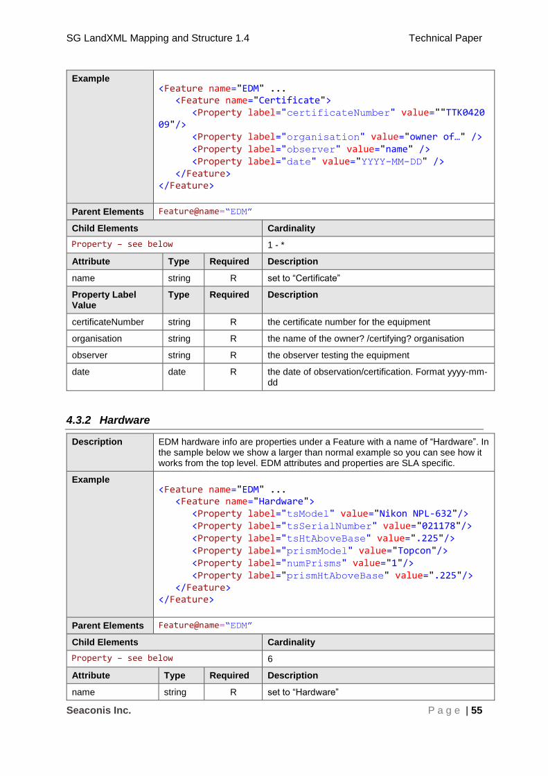
SG LandXML Mapping and Structure 1.4 Technical Paper
Seaconis Inc. P a g e | 55
Example <Feature name="EDM" ... <Feature name="Certificate"> <Property label="certificateNumber" value=""TTK042009"/> <Property label="organisation" value="owner of…" /> <Property label="observer" value="name" /> <Property label="date" value="YYYY-MM-DD" /> </Feature> </Feature>
Parent Elements Feature@name=“EDM”
Child Elements Cardinality
Property – see below 1 - *
Attribute Type Required Description
name string R set to “Certificate”
Property Label Value
Type Required Description
certificateNumber string R the certificate number for the equipment
organisation string R the name of the owner? /certifying? organisation
observer string R the observer testing the equipment
date date R the date of observation/certification. Format yyyy-mm-dd
4.3.2 Hardware
Description EDM hardware info are properties under a Feature with a name of “Hardware”. In the sample below we show a larger than normal example so you can see how it works from the top level. EDM attributes and properties are SLA specific.
Example <Feature name="EDM" ... <Feature name="Hardware"> <Property label="tsModel" value="Nikon NPL-632"/> <Property label="tsSerialNumber" value="021178"/> <Property label="tsHtAboveBase" value=".225"/> <Property label="prismModel" value="Topcon"/> <Property label="numPrisms" value="1"/> <Property label="prismHtAboveBase" value=".225"/> </Feature> </Feature>
Parent Elements Feature@name=“EDM”
Child Elements Cardinality
Property – see below 6
Attribute Type Required Description
name string R set to “Hardware”

SG LandXML Mapping and Structure 1.4 Technical Paper
Seaconis Inc. P a g e | 56
Property Label Value
Type Required Description
tsModel string R Total Station model number.
tsSerialNumber string R Serial number of Total Station.
tsHtAboveBase number R Height from base plate (metres) of Total Station.
prismModel string R Reflector(Prism) Model
numPrisms integer R number of prisms
prismHtAboveBase double R Height from base plate (m) of Reflector.
4.3.3 ResidualSeries
Description EDM residuals are properties under a Feature with a name of “ResidualSeries”. The residuals relate to measures between seven stations. They are reported in a series, starting with the measures from station one to the others six (n-1), then station two to the remaining five (n-2), and so on until the single measure (n-6) from station six to station seven. We will not show diagrams for all Properties separately, this diagram shows Property Labels.
The values are not placed in attributes, but are placed between the start and end tags. EDM attributes and properties are SLA specific. They are not in ICSM or LandXML.
Example ... <Feature name="ResidualSeries"> <Property label="series1" value="0.001, 0.000, 0.001, 0.002, 0.003, -0.002"/> <Property label="series2" value="0.001, -0.001, 0.002, 0.003, -0.001"/> <Property label="series3" value="-0.002, -0.001, 0.001, -0.004"/> <Property label="series4" value="0.000, 0.001, -0.003"/> <Property label="series5" value="0.004, -0.004"/> <Property label="series6" value="-0.001"/> </Feature> ...
Parent Elements Feature@name=“EDM”
Child Elements Cardinality
Property – see below 6
Attribute Type Required Description
name string R set to “ResidualSeries”
Property Label Value
Type Required Description
series1 double R six residual values
series2 double R five residual values
series3 double R four residual values
series4 double R three residual values
series5 double R two residual values
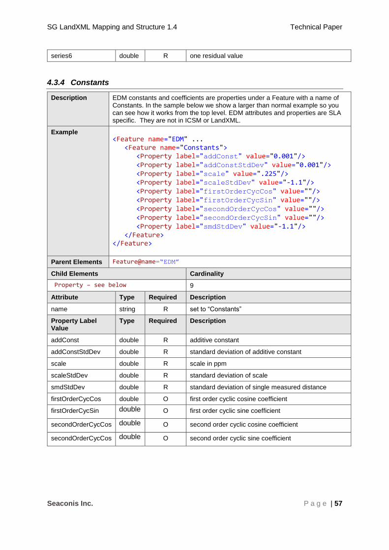
SG LandXML Mapping and Structure 1.4 Technical Paper
Seaconis Inc. P a g e | 57
series6 double R one residual value
4.3.4 Constants
Description EDM constants and coefficients are properties under a Feature with a name of Constants. In the sample below we show a larger than normal example so you can see how it works from the top level. EDM attributes and properties are SLA specific. They are not in ICSM or LandXML.
Example <Feature name="EDM" ... <Feature name="Constants"> <Property label="addConst" value="0.001"/> <Property label="addConstStdDev" value="0.001"/> <Property label="scale" value=".225"/> <Property label="scaleStdDev" value="-1.1"/> <Property label="firstOrderCycCos" value=""/> <Property label="firstOrderCycSin" value=""/> <Property label="secondOrderCycCos" value=""/> <Property label="secondOrderCycSin" value=""/> <Property label="smdStdDev" value="-1.1"/> </Feature> </Feature>
Parent Elements Feature@name=“EDM”
Child Elements Cardinality
Property – see below 9
Attribute Type Required Description
name string R set to “Constants”
Property Label Value
Type Required Description
addConst double R additive constant
addConstStdDev double R standard deviation of additive constant
scale double R scale in ppm
scaleStdDev double R standard deviation of scale
smdStdDev double R standard deviation of single measured distance
firstOrderCycCos double O first order cyclic cosine coefficient
firstOrderCycSin double O first order cyclic sine coefficient
secondOrderCycCos double O second order cyclic cosine coefficient
secondOrderCycCos double O second order cyclic sine coefficient
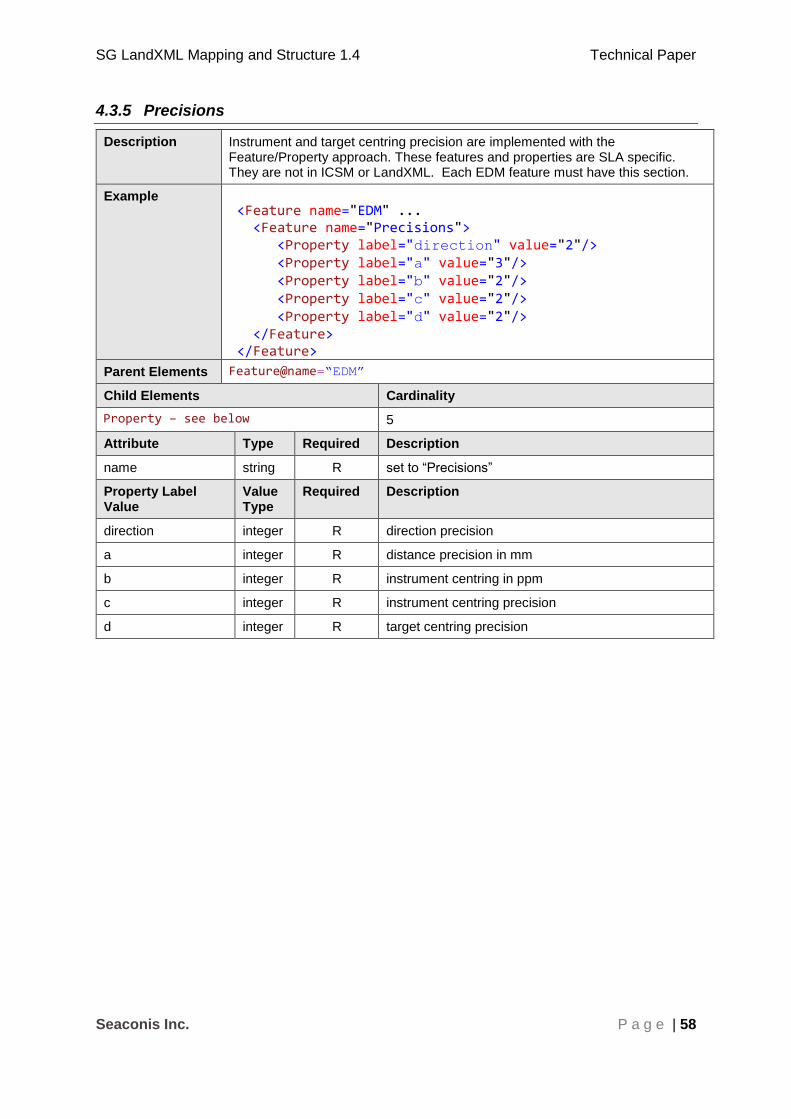
SG LandXML Mapping and Structure 1.4 Technical Paper
Seaconis Inc. P a g e | 58
4.3.5 Precisions
Description Instrument and target centring precision are implemented with the Feature/Property approach. These features and properties are SLA specific. They are not in ICSM or LandXML. Each EDM feature must have this section.
Example <Feature name="EDM" ... <Feature name="Precisions"> <Property label="direction" value="2"/> <Property label="a" value="3"/> <Property label="b" value="2"/> <Property label="c" value="2"/> <Property label="d" value="2"/> </Feature> </Feature>
Parent Elements Feature@name=“EDM”
Child Elements Cardinality
Property – see below 5
Attribute Type Required Description
name string R set to “Precisions”
Property Label Value
Value Type
Required Description
direction integer R direction precision
a integer R distance precision in mm
b integer R instrument centring in ppm
c integer R instrument centring precision
d integer R target centring precision

SG LandXML Mapping and Structure 1.4 Technical Paper
Seaconis Inc. P a g e | 59
4.4 Occupational Details
This section specifies the structures used to encode occupations and encroachments.
4.4.1 Introduction
The term “occupational details” is found within the CS Directive. It refers to features of the
built environment which are surveyed or “picked up” by conventional Land Survey
techniques. The CS directive does not specifically state what method to use when surveying
these details.
Encroachment information consists of occupational details along a boundary line for the
purposes of determining if there is encroachment. Occupation details are features which
may be polygon, line or point based. Encroachment may be encoded as a property of an
occupation feature, or determined by intersection of features.
The reason for inclusion of these features in LandXML is to provide a structure which could
allow sketch information to be included in the LandXML, and thereby remove one of the
reasons for sketch creation.
Occupational details have no requirement to be tied to the field survey objects. They are to
be modelled with coordinates only, not stations of the survey.
4.4.2 Occupations
Description A single PlanFeatures element is the container for all occupation detail. It will
have the name attribute set to “Occupations”. Encroachments, if occurring, will be held in separate PlanFeatures containing element. This is part of the
custom structural ‘template’ for occupations in SG.
Example <LandXML> ... <PlanFeatures name="Occupations"> <PlanFeature name="Wall"…> ... </PlanFeature> ... </PlanFeatures> </LandXML>
Parent Elements LandXML
Child Elements Cardinality
Occupation (templated PlanFeature) *
Attribute Type Required Description
name string R Set to "Occupations" for this template type.
4.4.3 Occupation
Description A custom PlanFeature element ‘template’ is used to represent an occupation in
SG. The occupation may be related to an encroachment. The sizeable example shows the use of different CoordGeom.

SG LandXML Mapping and Structure 1.4 Technical Paper
Seaconis Inc. P a g e | 60
Example <PlanFeatures name="Occupations"> <PlanFeature name ="Fence1"> <CoordGeom> <Line> <Start>38247.074 30475.959</Start> <End>38244.076 30474.841</End> </Line> <Line> <Start>38246.938 30476.324</Start> <End>38251.719 30463.484</End> </Line> <Line> <Start>38244.075 30474.841</Start> <End>38243.939 30475.207</End> </Line> <Line> <Start>38246.938 30476.324</Start> <End>38243.939 30475.207</End> </Line> </CoordGeom> <Feature name="occProps"> <Property label="code" value="fence" /> <Property label="group" value="A" /> <Property label="geometry" value="line" /> <Property label="pclRef" value="MK18-40001B" /> </Feature> </PlanFeature> <PlanFeature name ="PW1"> <CoordGeom> <IrregularLine> <Start>38247.074 30475.959</Start> <End>38247.074 30475.959</End> <PntList2D> 38247.074 30475.959 38244.076 30474.841 38246.938 30476.324 38251.719 30463.484 38244.075 30474.841 38243.939 30475.207 38246.938 30476.324 38247.074 30475.959 </PntList2D> </IrregularLine> </CoordGeom> <Feature name="occProps"> <Property label="code" value="party-wall" /> <Property label="group" value="Building B" /> <Property label="geometry" value="polygon" /> <Property label="pclRef" value="MK18-40001A" /> <Property label="pclRef" value="MK18-40002B" /> </Feature> </PlanFeature> </PlanFeatures>
Parent Elements PlanFeatures@name=“Occupations”
Child Elements Cardinality
CoordGeom 1
Feature/Properties 1

SG LandXML Mapping and Structure 1.4 Technical Paper
Seaconis Inc. P a g e | 61
Attribute Type Required Description
name string R An identifier for the occupation.
desc string O Description of the occupation.
4.4.4 Occupation Properties
Description This is a custom Feature to contain occupation properties.
Example <Feature name=”occProps"> <Property label="code" value="fence" /> <Property label="group" value="one" /> <Property label="geometry" value="line" /> <Property label="pclRef" value="MK18-40001B" /> </Feature>
Parent Elements
Occupation PlanFeature
Child Elements Cardinality
Property@label=“ code” 1
Property@label=“ group” 0-1
Property@label=“geometry” 1
Property@label=“ pclRef” 0-*
Attribute Type Required Description
name string R Set to "occProps". This identifies the Feature as the container of the occupation parameters.
Property Label
Value Type Required Description
code occCodeType R SG enumeration of allowed occupation types.
group string O Allows grouping of occupations for easier referencing.
geometry geomType R SG enumeration of geometry type: polygon, line and point.
pclRef string C The name of the owning parcel. This use of pclRef matches the use as attribute of parcels. It establishes a composite relationship between occupations and the parcel.
4.4.5 Encroachments
Description A single PlanFeatures element is the container for all encroachments. Encroachments can be polygons with a stated area, or linear with a stated length, or point.

SG LandXML Mapping and Structure 1.4 Technical Paper
Seaconis Inc. P a g e | 62
Example <LandXML> ... <PlanFeatures name="Encroachments"> <PlanFeature name="E1" desc=" Part of fence encroaching onto lot MK18-13579P "> ... </PlanFeature> ... </PlanFeatures> </LandXML>
Parent Elements LandXML
Child Elements Cardinality
Encroachment PlanFeature 0-*
Attribute Type Required Description
name string R Set to "Encroachments"
desc string O Descriptive information
4.4.6 Encroachment
Description An encroachment is encoded as a special structural ‘template’ of the PlanFeature element. An encroachment can be related to an occupation by
reference to the Occupation@name attribute value.
Example <PlanFeatures name="Encroachments"> <PlanFeature name ="E1" desc="Part of fence encroaching onto lot MK10-123456M"> <CoordGeom> <IrregularLine> <Start>38244.076 30474.841</Start> <End>38243.939 30475.207</End> <PntList2D> 38244.076 30474.841 38246.938 30476.324 38246.938 30476.324 38244.076 30474.841 </PntList2D> </IrregularLine> </CoordGeom> <Feature name="encProps"> <Property label="code" value="fence" /> <Property label="geometry" value="polygon" /> <Property label="pclRef" value="MK18-40001B" /> <Property label="occRef" value="Fence1" /> <Property label="area" value="3.4" /> </Feature> </PlanFeature> </PlanFeatures>
Parent Elements PlanFeatures@name=“Encroachments”
Child Elements Cardinality
CoordGeom 1
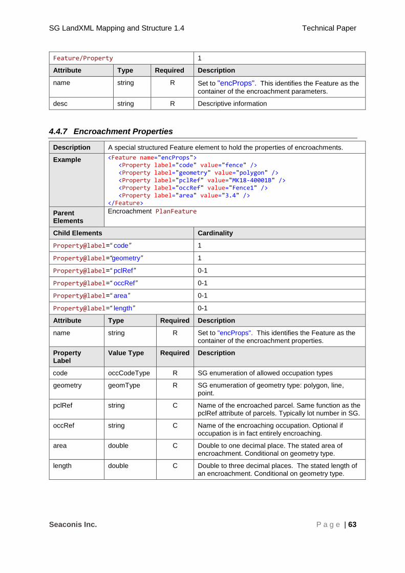
SG LandXML Mapping and Structure 1.4 Technical Paper
Seaconis Inc. P a g e | 63
Feature/Property 1
Attribute Type Required Description
name string R Set to "encProps". This identifies the Feature as the
container of the encroachment parameters.
desc string R Descriptive information
4.4.7 Encroachment Properties
Description A special structured Feature element to hold the properties of encroachments.
Example <Feature name="encProps"> <Property label="code" value="fence" /> <Property label="geometry" value="polygon" /> <Property label="pclRef" value="MK18-40001B" /> <Property label="occRef" value="Fence1" /> <Property label="area" value="3.4" /> </Feature>
Parent Elements
Encroachment PlanFeature
Child Elements Cardinality
Property@label=“ code” 1
Property@label=“geometry” 1
Property@label=“ pclRef” 0-1
Property@label=“ occRef” 0-1
Property@label=“ area” 0-1
Property@label=“ length” 0-1
Attribute Type Required Description
name string R Set to "encProps". This identifies the Feature as the container of the encroachment properties.
Property Label
Value Type Required Description
code occCodeType R SG enumeration of allowed occupation types
geometry geomType R SG enumeration of geometry type: polygon, line, point.
pclRef string C Name of the encroached parcel. Same function as the pclRef attribute of parcels. Typically lot number in SG.
occRef string C Name of the encroaching occupation. Optional if occupation is in fact entirely encroaching.
area double C Double to one decimal place. The stated area of encroachment. Conditional on geometry type.
length double C Double to three decimal places. The stated length of an encroachment. Conditional on geometry type.

SG LandXML Mapping and Structure 1.4 Technical Paper
Seaconis Inc. P a g e | 64
4.5 Levelling
The common method for determination of elevation in SG is levelling. A levelling loop
begins from a position of known elevation, typically a Vertical Control Point (VCP), and
continues through a number of positions until arriving back where it began. Points where
elevations are needed are visited along the levelling loop. Changes in height along the loop
are used to calculate elevations for these specific stations of interest in the survey. Distance
should be recorded between the positions and can then be used in misclose (vertical)
calculations as defined in the CSD4.
Since there are no northings or eastings for change points, normal LandXML encoding as
traverses and CgPoint are not appropriate. Instead, we encode the levelling field information
in a manner similar to Level Detail Sheets (Level Booking forms); either all point to point
calculations or only raw values. If only raw values are recorded, resultant adjusted
elevations can be calculated against the CgPoint z values for the named stations in the
levelling data.
<SurveyHeader>
... <Feature name="LevellingDetails"> <Feature name="Loop1"> <Property label="from" value="VCP80172"/> <Property label="to" value="VCP80172"/> <Property label="misclose" value="0.002"/> <Property label="totalDistance" value="1.3"/> <Feature name="VcpIntegrityCheck"> <Feature name="VCP"> <Property label="stn" value="VCP80172"/> <Property label="bs" value="1.463"/> <Property label="al" value="110.891"/> </Feature> <Feature name="detail"> <Property label="stn" value="W2"/> <Property label="is" value="1.462"/> <Property label="rl" value="110.892"/> <Property label="al" value="110.894"/> <Property label="rmk" value="witness mark 2"/> </Feature> <Feature name="detail"> <Property label="stn" value="W1"/> <Property label="is" value="1.492"/> <Property label="rl" value="110.862"/> <Property label="al" value="110.863"/> <Property label="rmk" value="witness mark 1"/> </Feature> </Feature> <Feature name="detail"> <Property label="stn" value="VCP80172"/> <Property label="bs" value="1.538"/> <Property label="rl" value="110.891"/> <Property label="al" value="110.891"/> </Feature> <Feature name="detail"> <Property label="stn" value="CP1"/> <Property label="bs" value="1.196"/> <Property label="is" value=""/> <Property label="fs" value="1.412"/> <Property label="rl" value="110.017"/> <Property label="al" value="110.017"/>
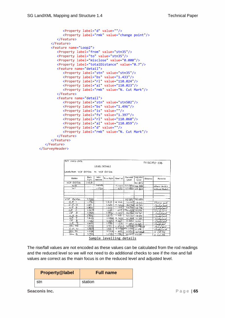
SG LandXML Mapping and Structure 1.4 Technical Paper
Seaconis Inc. P a g e | 65
<Property label="d" value=""/> <Property label="rmk" value="change point"/> </Feature> </Feature> <Feature name="Loop2"> <Property label="from" value="stn35"/> <Property label="to" value="stn35"/> <Property label="misclose" value="0.000"/> <Property label="totalDistance" value="0.7"/> <Feature name="detail"> <Property label="stn" value="stn35"/> <Property label="bs" value="1.433"/> <Property label="rl" value="110.024"/> <Property label="al" value="110.023"/> <Property label="rmk" value="N. Cut Mark"/> </Feature> <Feature name="detail"> <Property label="stn" value="stn502"/> <Property label="bs" value="1.496"/> <Property label="is" value=""/> <Property label="fs" value="1.397"/> <Property label="rl" value="110.060"/> <Property label="al" value="110.059"/> <Property label="d" value=""/> <Property label="rmk" value="N. Cut Mark"/> </Feature> </Feature> </Feature> </SurveyHeader>
Sample levelling details
The rise/fall values are not encoded as these values can be calculated from the rod readings
and the reduced level so we will not need to do additional checks to see if the rise and fall
values are correct as the main focus is on the reduced level and adjusted level.
Property@label Full name
stn station

SG LandXML Mapping and Structure 1.4 Technical Paper
Seaconis Inc. P a g e | 66
Property@label Full name
bs back sight
is intermediate sight
fs fore sight
rl reduced level
al adjusted level
d distance
rmk remarks
Conventions are needed for:
1. Standardization of naming the points so that traverse stations and VCPs can be identified.
2. Values to standardize to be recorded meters.
5 Complex Structures and Scenarios
This section introduces higher level use of LandXML elements in the preparation of
LandXML files for submission to SLA using CSMS. The section describes SG specific
situations and conditions along with a “recipe” for creating a valid SGLX file.
5.1 Parcels
This section describes aspects of parcels (lots), including common attributes and special SG
enumerations and properties required to represent the complexity of lots and areas in
Singapore.
There are a number of non-lot polygons that are represented as Parcels. Only lots have lot
numbers assigned by SLA, which must be used in the submissions. Areas and volumes
may not be required. These non-lot areas include state reserves, voids, level outlines and
common properties.
5.1.1 Parcel
The following shows the complete LandXML Parcel structure including all the sub elements
that reside within a Parcel.
<!-- Root LandXML element, container for all CIF elements -->
<LandXML...>
...
<!-- Container for all Parcel elements -->
<Parcels>
<!-- Each discrete parcel is described by a parcel element -->
<Parcel ...="">
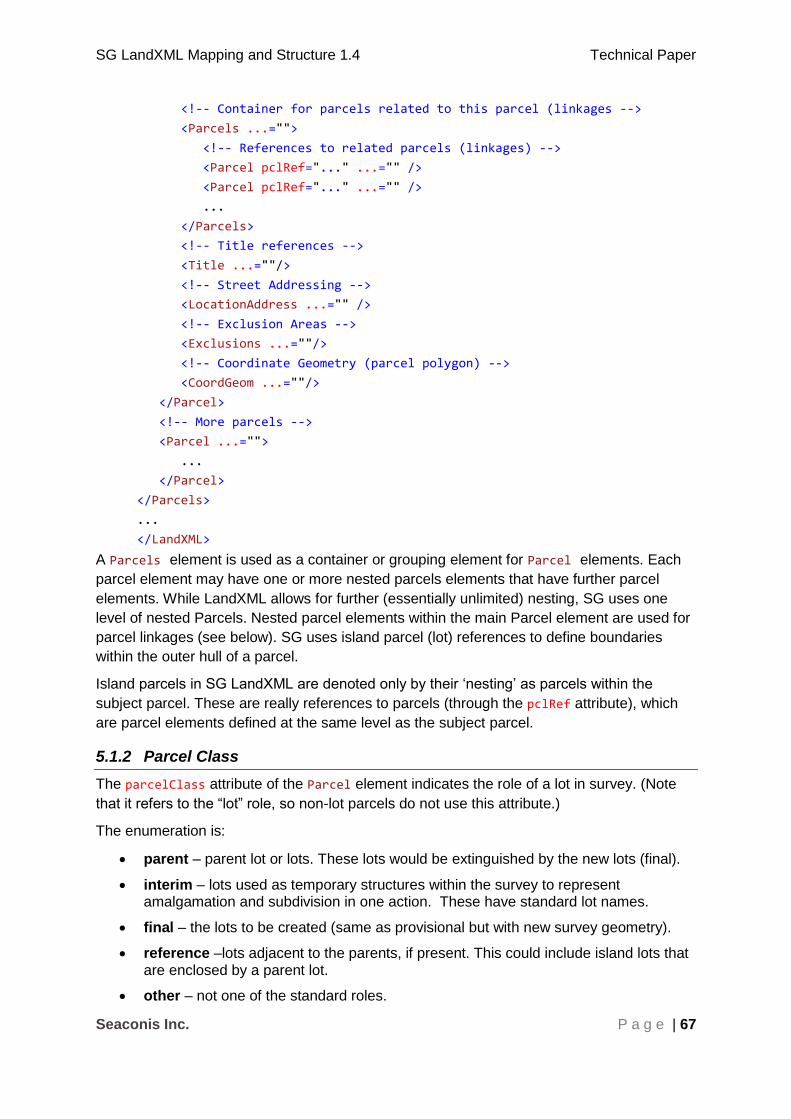
SG LandXML Mapping and Structure 1.4 Technical Paper
Seaconis Inc. P a g e | 67
<!-- Container for parcels related to this parcel (linkages -->
<Parcels ...="">
<!-- References to related parcels (linkages) -->
<Parcel pclRef="..." ...="" />
<Parcel pclRef="..." ...="" />
...
</Parcels>
<!-- Title references -->
<Title ...=""/>
<!-- Street Addressing -->
<LocationAddress ...="" />
<!-- Exclusion Areas -->
<Exclusions ...=""/>
<!-- Coordinate Geometry (parcel polygon) -->
<CoordGeom ...=""/>
</Parcel>
<!-- More parcels -->
<Parcel ...="">
...
</Parcel>
</Parcels>
...
</LandXML>
A Parcels element is used as a container or grouping element for Parcel elements. Each
parcel element may have one or more nested parcels elements that have further parcel
elements. While LandXML allows for further (essentially unlimited) nesting, SG uses one
level of nested Parcels. Nested parcel elements within the main Parcel element are used for
parcel linkages (see below). SG uses island parcel (lot) references to define boundaries
within the outer hull of a parcel.
Island parcels in SG LandXML are denoted only by their ‘nesting’ as parcels within the
subject parcel. These are really references to parcels (through the pclRef attribute), which
are parcel elements defined at the same level as the subject parcel.
5.1.2 Parcel Class
The parcelClass attribute of the Parcel element indicates the role of a lot in survey. (Note
that it refers to the “lot” role, so non-lot parcels do not use this attribute.)
The enumeration is:
parent – parent lot or lots. These lots would be extinguished by the new lots (final).
interim – lots used as temporary structures within the survey to represent amalgamation and subdivision in one action. These have standard lot names.
final – the lots to be created (same as provisional but with new survey geometry).
reference –lots adjacent to the parents, if present. This could include island lots that are enclosed by a parent lot.
other – not one of the standard roles.

SG LandXML Mapping and Structure 1.4 Technical Paper
Seaconis Inc. P a g e | 68
In one sense, the parcel classes are states used to track the provenance of a lot through its
life stages. In another, they combine with lineage to describe the process of the survey.
5.1.3 Parcel Lineage
Given the parcel class, we can track changes to parcels from parents through final, with the
addition of lineage information. There are two basic operations (processes): subdivision and
amalgamation. These are expressed using the equality and addition symbols and a few
rules to create a type of algebra. Equality is the suggestion of conservation of area.
1. A process is represented by an equation.
2. Input parcels are on the left of the equal sign and output parcels are on the right.
3. Subdivision is represented by one input parcel and multiple output parcels: A = B+C
4. Amalgamation is shown as multiple input parcels and one output parcel: A+B = C
5. Alteration of a single parcel by A = B
6. Single lot survey or verification can be represented by A = A
7. A new parcel can be represented by NEW = A

SG LandXML Mapping and Structure 1.4 Technical Paper
Seaconis Inc. P a g e | 69
1
3
2
1
4
1
987
5 6
987
5
10
These parcels have a parcel class of “parent”. They are the currently active lots in the CSMS fabric.
Parcels 2 and 3 have been amalgamated to yield parcel 4.
This is represented as:
P2+ P3 = P4
Parcel 4 is then subdivided, yielding parcels 5,6,7,8 and 9.
This is represented as:
P4 = P5 + P6 + P7 + P8 + P9
Parcel 1 and parcel 6 are then amalgamated to give parcel 10.
This is represented as:
P1 + P6 = P10
SG LandXML Mapping and Structure 1.4 Technical Paper
Seaconis Inc. P a g e | 70
So given a LandXML with the parcel geometry and the parcel class, a single character string
of “P2+P3=P4; P4=P5+P6+P7+P8+P9; P1+P6=P10” could convey the entire sequence.
Parcels to the left of the equals sign are extinguished and those on the right are created.
The final diagram shows all parcels with a class of “final”.
In practice, the names would be replaced by lot numbers are interim names. It is also
possible that not all geometry would need to be included in the LandXML. Interim parcels
that are amalgamations can be represented just as a name.
The lineage would be held in a property that is a child to the SurveyHeader as shown below.
<Feature name="Lineage"> <Property label="lineage" value="P2+P3=P4;P4=P5+P6+P7+P8+P9;P1+P6=P10"/> <Property label="physicalRelation" value="P5=P2;P7=P2+P3;P8=P3;P9=P3;P10=P1+P2"/> </Feature>
This approach can represent known SG processes. The representation is focused on the
use of lot names.
For instance:
1. Subdivision: P1 = P2 + P3
2. Amalgamation: P1 + P2 = P3
3. Alteration: P1 = P2
4. Verification P1 = P1
5. Proclamation NEW = P1
NEW is not a lot name, but is used to indicate that there is no parent. Process
representations should be extensible to handle new situations.
Clearly, there is a relationship between the process types shown here and the
PurposeOfSurvey aspect JobType. The usefulness of the relationship in quality control and
testing is complicated by the multiplicity of processes possible within some types of
submissions.
Examples
Amalgamation and subdivision:
<Property label="lineage"
value="MK28-07437T+MK28-07436P=MK28-07412N"/>
In the case of submission:
<Property label="lineage" value="MK28-07412N=MK28-07437T+MK28-07436P"/>
Alteration:
SG LandXML Mapping and Structure 1.4 Technical Paper
Seaconis Inc. P a g e | 71
<Property label="lineage"
value="MK12-12345A=MK13-23456D"/> Verification:
<Property label="lineage"
value="MK12-12345A=MK12-12345A"/> Proclamation:
<Property label="lineage"
value="NEW=MK12-U12345A;NEW=MK12-12346B"/>
The same processes apply to Strata parcels in the submission file.
Amalgamation and subdivision:
<Property label="lineage"
value="MK12-U123456A+MK12-U123467B=MK12-U123560A;MK12-U123560A=MK12-U123511B+MK12-U123512C+MK12-U123513D"/>
Alteration:
<Property label="lineage"
value="MK12-U123456A=MK13-U234567D"/> Verification:
<Property label="lineage"
value="MK12-U123456A=MK12-U123456A"/> Proclamation:
<Property label="lineage" value="NEW=MK12-U123456A;NEW=MK12-U123467B"/>
5.1.4 Physical Relationship
A second, physical, relationship maps the final lots back to the parent lots which they overlie.
This is also described with our lineage algebra, but with a different contextual meaning. In
the example above, the physical relation property shows that lot P5 has only lot P2 as its
physical origin. However, lot P10 overlies some or all of each of the parent lots P1and P2.
This gives a direct relationship regardless the possible convolutions on amalgamations and
subdivisions in the interim and dummy lots.

SG LandXML Mapping and Structure 1.4 Technical Paper
Seaconis Inc. P a g e | 72
The physicalRelation property should be formulated with the final lot on the left, and the
physical parent lots on the right of the equals sign. This is the opposite of lineage which has
parent lots to the left.
This shows the physical relationships derived from a
geometric intersection of the parent lots and the final child
lots. Lots 1,2 and 3 are parents, and 5,7,8,9,10 are final
lots. The physical relation of lot 7 is 2 and 3.
This is an example of the lineage construct with both the lineage and physical relation
properties
<Feature name="Lineage"> <Property label="lineage" value="MK28-07412N=MK28-07437T+MK28-07436P" /> <Property label="physicalRelation" value="MK28-07437T=MK28-07412N;MK28-07436P=MK28-07412N" /> </Feature>
5.1.5 State Reserve
The state reserve (SR) is similar to an easement in other cadastres. The SR is a polygon
overlying all or some part of a lot. It does not have a Lot Number, but contains a reference
to the Lot Number of the burdened lot.
5.1.5.1 Name Convention
State Reserve areas do not currently have a name assigned by SLA, yet they are tracked.
Yet preparation of the submission must follow a naming convention that CSMS software can
use to correctly identify these areas, and names are required by LandXML for all parcel
elements.
The convention is ”SRxxxx” where the x values are a number series assigned by the
surveyor and unique to the submission file.
5.1.5.2 Attributes
State Reserves are an oddity in SG. Although we model them using the Parcel element,
they are not lots, and are not treated as lots. Important attributes are defined below.
1. name – follows convention “SRxxxx” assigned unique number by surveyor.
2. parcelFormat – “standard”. No SR’s for other than land survey.
3. parcelType – “stateReserve”.
4. parcelClass – “other”
1
3
2
9
8
7
5
10
SG LandXML Mapping and Structure 1.4 Technical Paper
Seaconis Inc. P a g e | 73
5.1.6 Balance Lot
A balance lot has some geometry from a preceding survey, and some from the subject
survey. It is created when a portion of the parent lot is “cut” from the parent, but only the cut
portion is surveyed. The remainder is the balance lot.
<Feature name="Balance"> <Property label="isBalanceLot" value="Y"/> </Feature>
5.1.7 Area Class and Description
SG requires, for LandXML export of old records, the properties of an area class to describe
the method or source of an area, and an area description, which is a textual description.
There are no attributes in the LandXML to accomplish this. We use Feature and Property
elements as shown below:
<Feature name="Area"> <Property label="class" value="S"/> <Property label="description" value="INCLUDES STRATA VOID OF 20 SQ M"/> <Property label="description" value="INCLUDES ACCESSORY VOID OF 1 SQ M"/> </Feature>
The need for this property will be rarely encountered, and never in a new survey. However,
software to read or write the LandXML must test for the existence or need when reading or
writing.
5.1.8 Old Format Lot Numbers
Old format lot numbers exist for titles that have not changed during the last update of the lot
number format. It is used as a reference for the land owners to refer to the old format lot
number as stated in their title deeds. So some lots will have both new lot number and old
format lot number. Surveyors are required to submit the old format lot number along with the
new format lot numbers for surveys and submissions that are initiated with lots using the old
format lot number. Therefore, Parcel needs a property to hold the old format lot number in
these cases. The property will be optional, and SG LandXML readers must test for its
existence.
<Feature name="OldFormat"> <Property label="oldFormatLotNumber" value="4287/U71"/> </Feature>
5.1.9 Survey Type
Indicates the survey type, and must be of type surveyTypeType: resurvey, substandard or
modern.
<Feature name="SurveyType"> <Property label="code" value="resurvey"/> </Feature>

SG LandXML Mapping and Structure 1.4 Technical Paper
Seaconis Inc. P a g e | 74
5.2 Voids
The term void covers two classes of parcel areas. The first is a situation which occurs when
land lots surround a not-a-lot, or void. This is a relatively rare situation, generally found in
foreshore areas, and probably always resulting from “new” land creation. The second class
of void lot is characteristic of airspace, subterranean, strata lots and building outlines.
5.2.1 Parcels
Voids will be modelled in LandXML as parcels, using the Parcel element. This has the
benefit of using a well attributed element of fundamental use in LandXML, which is most
efficient and will allow for future enhancement of the void model. All the attributes of the Sg
specific parcel can be used in their selection and treatment by CSMS software.
5.2.2 Name Convention
Void areas do not currently have a name assigned by SLA, yet they are tracked. However,
preparation of the submission must follow a naming convention that CSMS software can use
to correctly identify these areas, and names are required by LandXML for all parcel
elements.
The convention is ”Sx” where the x value is a number in a series assigned by the surveyor
and unique to the submission file.
5.2.3 Attributes
Voids are identified by the name prefix, but also by their attributes.
1. name – follows convention
2. parcelFormat = standard
3. parcelType = ”empty”
4. parcelClass = ”other”
Area and volume need not be calculated and reported by the surveyor. In cases where they
are reported, it will be assumed there was a specific reason.
5.2.4 Land Lot Void
The void land lot in Singapore is not just a “gap” created by a mistake in the adjoining
boundaries of lots. In a few cases in Singapore, large areas have been enclosed by lots.
This seems to be solely an issue with foreshore areas, where the creation of new land for
breakwaters, linking roads, seaports and shipyards, encloses a body of water.
This creates two situations, each with a different outcome and need for resolution. Firstly, if
a void area is created by multiple lots, then the enclosure is “outside of each. As we have
proposed a “foreshore” survey method for points, and therefore boundary points, we have a
hook for analysis of the situation. Also, the foreshore point or monument is by definition not
expected to fall on a shared boundary. So, although there is an enclosure of water, it does
not break any rules we have in lot formation. If we want to measure the area enclosed, we
can do so by finding “rings” of foreshore boundaries.
The second situation is not easily resolved without forming a new concept of “lots”. If a
single lot encloses a body of water, then we have created a boundary definition issue for the

SG LandXML Mapping and Structure 1.4 Technical Paper
Seaconis Inc. P a g e | 75
lot. In our current land model, lots are allowed to have an “implied” inner boundary. This
boundary is the boundary of an island lot, which has its own boundary definition. So without
an island lot representing the enclosed water body, we cannot fit this oddity into our model.
Such a situation might arise through an amalgamation of all lots participating in the
enclosure. Perhaps such things might be disallowed. Alternatively, we should look to the
solution of a general void lot, needed for subterranean, airspace and strata, for a way to
handle the same problem with voids in land lots.
5.3 Airspace and Subterranean Lots
Airspace and subterranean lots have distinctive characteristics that separate them from land
lots. They are three dimensionally defined parcels, but represented as 2D in current
practice. This section addresses unique aspects of these lots, and makes suggestions for
new approaches.
Airspace and Subterranean lots have levelling field data and calculations to yield the
elevations required for definition of the surveys. The specific format of levelling detail is
shown in its own section (4.5 Levelling).
5.3.1 Airspace Lot Boundaries
Airspace lot boundaries are defined by demarcation (observations) from the standard land
survey. The “outside” points defining each lot are connected to traverse stations. These
airspace lots are defined as extrusions from the 2D lot definitions using lower and upper
elevations defining the vertical extent of each lot.
The elevation defining the separation between overlying lots is generally established as the
middle of a physical structure between the lots (middle of the occupation).
Levelling is used to define the elevations of at least a part of the stations of the traverse,
though not necessarily all stations defining the lot boundaries. Engineering and architectural
plans are often used as supporting documentation of the elevations defining the lots.
Elevation reference pairs, discussed in the section on Elevations (section 5.14), are used to
encode the upper and lower elevations of airspace and subterranean lots, as a child Feature
construct within the Parcel element, as shown below.
<Feature name="ElevRefPair"> <Property label="lower" value="level 3"/> <Property label="upper" value="level 3 false ceiling"/> </Feature>
The referenced elevations can be retrieved from the Elevations structure of the
SurveyHeader. Airspace lots may also be Part Lots, which have a special encoding and lot
naming convention described in a following section.
5.3.2 Subterranean Boundaries
Subterranean (sub) lots have a very distinct characteristic. The boundary points of the
underground structures are on the outside of the walls, and not accessible to direct
measurement. That is, they are not connected to the traverse, side shots, observations, and
demarcations of the survey. Instead, their values must be calculated from interior
measurements.
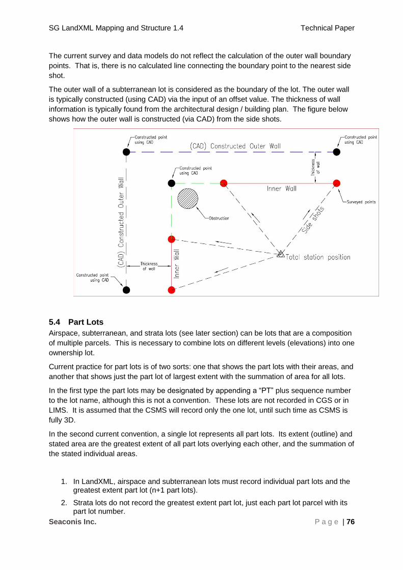
SG LandXML Mapping and Structure 1.4 Technical Paper
Seaconis Inc. P a g e | 76
The current survey and data models do not reflect the calculation of the outer wall boundary
points. That is, there is no calculated line connecting the boundary point to the nearest side
shot.
The outer wall of a subterranean lot is considered as the boundary of the lot. The outer wall
is typically constructed (using CAD) via the input of an offset value. The thickness of wall
information is typically found from the architectural design / building plan. The figure below
shows how the outer wall is constructed (via CAD) from the side shots.
5.4 Part Lots
Airspace, subterranean, and strata lots (see later section) can be lots that are a composition
of multiple parcels. This is necessary to combine lots on different levels (elevations) into one
ownership lot.
Current practice for part lots is of two sorts: one that shows the part lots with their areas, and
another that shows just the part lot of largest extent with the summation of area for all lots.
In the first type the part lots may be designated by appending a “PT” plus sequence number
to the lot name, although this is not a convention. These lots are not recorded in CGS or in
LIMS. It is assumed that the CSMS will record only the one lot, until such time as CSMS is
fully 3D.
In the second current convention, a single lot represents all part lots. Its extent (outline) and
stated area are the greatest extent of all part lots overlying each other, and the summation of
the stated individual areas.
1. In LandXML, airspace and subterranean lots must record individual part lots and the greatest extent part lot (n+1 part lots).
2. Strata lots do not record the greatest extent part lot, just each part lot parcel with its part lot number.
SG LandXML Mapping and Structure 1.4 Technical Paper
Seaconis Inc. P a g e | 77
3. Part lot naming convention is to append “PT” + sequential number to the lot names.
Part lots including a greatest extent part lot:
<Parcel name="MK05-70002K-PT1" area="2000.0" …> ...
<Feature name="PartLot"> <Property label="TotalArea" value="3000.0"/> </Feature> </Parcel> <Parcel name="MK05-70002K-PT2" area="1000.0" …> ... </Parcel> <Parcel name="MK05-70002K-GE" area="2445.6" …> ... </Parcel>
5.5 SG Modified ICSM Structuring Spatial Elements
The following elements in a CIF contain spatial information:
All elements under CoordGeom (e.g. Line, Curve, IrregularLine)
All elements under ObservationGroup
CgPoint elements
Coordinate geometry (CoordGeom) elements are used to store 2D and 3D line and polygon
structures for Parcel and PlanFeature elements. A CoordGeom element must be a child of a
Parcel or PlanFeature element.
Observation elements are contained within an ObservationGroup element and are used for
measurement and dimension information.
Note: In Singapore, traverses have a strong role and will each be modelled as an
ObservationGroup.
CgPoints are single points that are used to build more complex structures such as lines, arcs
and polygons and:
To associate observation and monument information with a point.
To store the position of a point for rendering purposes.
CgPoint elements are all contained within a CgPoints element and are referenced using their
name attribute. Other elements that are associated with a particular CgPoint have a pntRef
attribute whose value is the name of the related CgPoint element. These include Line, Curve,
Monument, ReducedObservation and others. For example, a Line in a CoordGeom has Start
and End nodes, which in turn reference CgPoint elements. Where a measurement or
dimension is required between two points, they are referenced by Observation elements
through InstrumentSetup elements.
CgPoint elements can store coordinate information for the node. In the Australian ICSM
national standard, they state that coordinates are used only for rendering purposes and
should not be used for any purpose requiring survey accurate data as CgPoint coordinates
may be distorted for display optimisation. The opposite is true for the Singapore LandXML
standard. CgPoint coordinate values are a product of the survey processes only, and reflect
the best estimate of locations. These coordinates are used for analytic as well as
cartographic purposes.
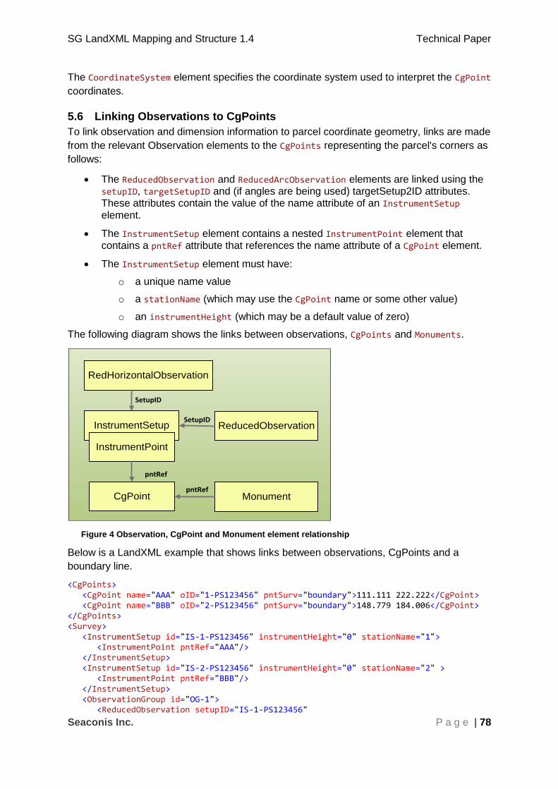
SG LandXML Mapping and Structure 1.4 Technical Paper
Seaconis Inc. P a g e | 78
The CoordinateSystem element specifies the coordinate system used to interpret the CgPoint
coordinates.
5.6 Linking Observations to CgPoints
To link observation and dimension information to parcel coordinate geometry, links are made
from the relevant Observation elements to the CgPoints representing the parcel's corners as
follows:
The ReducedObservation and ReducedArcObservation elements are linked using the setupID, targetSetupID and (if angles are being used) targetSetup2ID attributes. These attributes contain the value of the name attribute of an InstrumentSetup element.
The InstrumentSetup element contains a nested InstrumentPoint element that contains a pntRef attribute that references the name attribute of a CgPoint element.
The InstrumentSetup element must have:
o a unique name value
o a stationName (which may use the CgPoint name or some other value)
o an instrumentHeight (which may be a default value of zero)
The following diagram shows the links between observations, CgPoints and Monuments.
InstrumentSetup
InstrumentPoint
ReducedObservation
CgPoint MonumentpntRef
RedHorizontalObservation
pntRef
SetupID
SetupID
Figure 4 Observation, CgPoint and Monument element relationship
Below is a LandXML example that shows links between observations, CgPoints and a
boundary line.
<CgPoints> <CgPoint name="AAA" oID="1-PS123456" pntSurv="boundary">111.111 222.222</CgPoint> <CgPoint name="BBB" oID="2-PS123456" pntSurv="boundary">148.779 184.006</CgPoint> </CgPoints> <Survey> <InstrumentSetup id="IS-1-PS123456" instrumentHeight="0" stationName="1"> <InstrumentPoint pntRef="AAA"/> </InstrumentSetup> <InstrumentSetup id="IS-2-PS123456" instrumentHeight="0" stationName="2" > <InstrumentPoint pntRef="BBB"/> </InstrumentSetup> <ObservationGroup id="OG-1"> <ReducedObservation setupID="IS-1-PS123456"

SG LandXML Mapping and Structure 1.4 Technical Paper
Seaconis Inc. P a g e | 79
targetSetupID="IS-2-PS123456" horizDistance="53.66" azimuth="314.3510" ...=""/> </ObservationGroup> </Survey> <Parcels> <Parcel name="" ...=""> <CoordGeom> <Line> <Start pntRef="AAA"></Start> <End pntRef="BBB"></End> </Line> ... </CoordGeom> </Parcel> </Parcels>
The above example shows how a line (Parcel/CoordGeom/Line) and its dimensions
(attributes of ReducedObservation) and rendering information (CgPoint coordinates) are
related using the CgPoint and InstrumentSetup elements in a CIF.
The following diagram is a representation of the above LandXML (note that CgPoint
coordinates are ordered northing, easting or y, x):
Figure 12: Linking observations and dimensions to lines
5.7 Horizontal Control
This section directly addresses the encoding of SG horizontal control in LandXML.
Alternative structural modes are proposed for efficiency in the standard transactions.
Note: ICSM LandXML, and to a large degree LandXML itself, treat control coordinates separate from the
station coordinates because they are not coordinated cadastres. In SG, we use control in the field as another
station; one who’s coordinates must match the coordinates on record, but then we expect that for all existing
points. This is fundamentally different, and allows us to use a much simpler model of control in LandXML.
5.7.1 Referenced in Surveys
The main use of control in SG surveys is as a reference, the control marker coordinates are
used to locate the survey traverse. In this use, there is no intention of changing the
coordinates of the control, or to make special measurements. The observations to the
control marker are the same as all other legs of the traverse, or in some cases - side shots.
The important thing is that the survey data file indicates which control marker is related to
which station of the traverse.
This model uses only the CgPoint and the Monument to hold information for the survey
submission. We rely on the Monument for CP related attribution. Since there are no
RedHorizontalPosition or RedVerticalObservation elements, there is no need for
integration in the core body of the Survey or the ObservationGroup.

SG LandXML Mapping and Structure 1.4 Technical Paper
Seaconis Inc. P a g e | 80
<CgPoints> ... <CgPoint name="4" desc="final" code="L01" pntSurv="control">
38311.396 30303.307 16.640 </CgPoint>
</CgPoints> ... <Monuments> ... <Monument name="SM80001" pntRef="4" type="SM" state="found" /> </Monuments>
This simple model requires no additional and unnecessary information in the survey files.
5.7.2 Detailed HCP Model
A single model for HCP supports both distribution from CSMS, and the encoding of
information for submission. Multiple HCP may be contained in a single LandXML.
The processes and data transfers for new control are extensive, and managed by on-line
submission of many files and forms, ranging from GPS certifications, to RINEX files and
graphics composite photographs. It is unclear how any LandXML adaptation to satisfy
encoding the complete set could itself be a functional and useful standard for SG.
Instead, a portion of the data will be encoded as LandXML, as close to the standard as
possible, and the other processes should support the balance. This proper subset of data
will be used for the distribution and submission purposes.
The only difference between distribution and submission for this protocol is:
The WGS84 latitude and longitude are not required in the submission.
The last updated date is not relevant for a submission.
Standard for CP Transactions. Asterisk indicates not in both download and new.
Standard HCP Transaction
Combined LandXML
cp number Monument@name
marker type Monument@type
Administrative
surveyor Feature/Property@label=”Surveyor”
assistant Feature/Property@label=”Authorised Assistant”
survey date Feature/Property@label=“SurveyDate”
Coordinates and Elevations
northing <CgPoint>northing easting elevation </CgPoint>
easting <CgPoint>northing easting elevation </CgPoint>
reduced level <CgPoint>northing easting elevation </CgPoint>
latitude (WGS84) * CgPoint@latitude
longitude (WGS84) * CgPoint@longitude
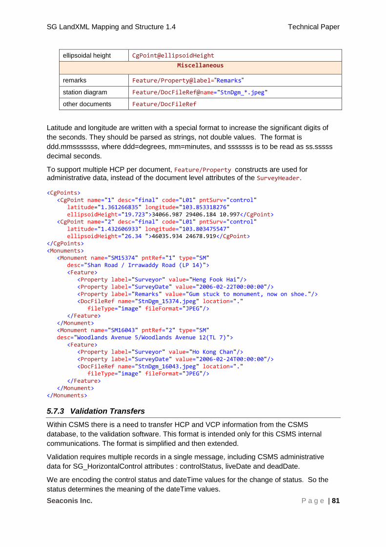
SG LandXML Mapping and Structure 1.4 Technical Paper
Seaconis Inc. P a g e | 81
ellipsoidal height CgPoint@ellipsoidHeight
Miscellaneous
remarks Feature/Property@label=”Remarks”
station diagram Feature/DocFileRef@name="StnDgm_*.jpeg"
other documents Feature/DocFileRef
Latitude and longitude are written with a special format to increase the significant digits of
the seconds. They should be parsed as strings, not double values. The format is
ddd.mmsssssss, where ddd=degrees, mm=minutes, and sssssss is to be read as ss.sssss
decimal seconds.
To support multiple HCP per document, Feature/Property constructs are used for administrative data, instead of the document level attributes of the SurveyHeader. <CgPoints> <CgPoint name="1" desc="final" code="L01" pntSurv="control" latitude="1.361266835" longitude="103.853318276" ellipsoidHeight="19.723">34066.987 29406.184 10.997</CgPoint> <CgPoint name="2" desc="final" code="L01" pntSurv="control" latitude="1.432606933" longitude="103.803475547" ellipsoidHeight="26.34 ">46035.934 24678.919</CgPoint> </CgPoints> <Monuments> <Monument name="SM15374" pntRef="1" type="SM" desc="Shan Road / Irrawaddy Road (LP 14)"> <Feature> <Property label="Surveyor" value="Heng Fook Hai"/> <Property label="SurveyDate" value="2006-02-22T00:00:00"/> <Property label="Remarks" value="Gum stuck to monument, now on shoe."/> <DocFileRef name="StnDgm_15374.jpeg" location="." fileType="image" fileFormat="JPEG"/> </Feature> </Monument> <Monument name="SM16043" pntRef="2" type="SM" desc="Woodlands Avenue 5/Woodlands Avenue 12(TL 7)"> <Feature> <Property label="Surveyor" value="Ho Kong Chan"/> <Property label="SurveyDate" value="2006-02-24T00:00:00"/> <DocFileRef name="StnDgm_16043.jpeg" location="." fileType="image" fileFormat="JPEG"/> </Feature> </Monument> </Monuments>
5.7.3 Validation Transfers
Within CSMS there is a need to transfer HCP and VCP information from the CSMS
database, to the validation software. This format is intended only for this CSMS internal
communications. The format is simplified and then extended.
Validation requires multiple records in a single message, including CSMS administrative
data for SG_HorizontalControl attributes : controlStatus, liveDate and deadDate.
We are encoding the control status and dateTime values for the change of status. So the
status determines the meaning of the dateTime values.
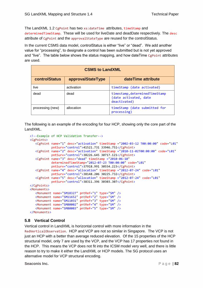
SG LandXML Mapping and Structure 1.4 Technical Paper
Seaconis Inc. P a g e | 82
The LandXML 1.2 CgPoint has two xs:dateTime attributes, timeStamp and
determinedTimeStamp. These will be used for liveDate and deadDate respectively. The desc
attribute of CgPoint and the approvalStateType are reused for the controlStatus.
In the current CSMS data model, controlStatus is either “live” or “dead”. We add another
value for “processing”, to designate a control has been submitted but is not yet approved
and “live”. The table below shows the status mapping, and how dateTime CgPoint attributes
are used.
CSMS to LandXML
controlStatus approvalStateType dateTime attribute
live activation timeStamp (date activated)
dead dead timestamp,determinedTimeStamp (date activated, date deactivated)
processing (new) allocation timeStamp (date submitted for processing)
The following is an example of the encoding for four HCP, showing only the core part of the
LandXML.
<!--Example of HCP Validation Transfer--> <CgPoints> <CgPoint name="1" desc="activation" timeStamp ="2002-03-12 T00:00:00" code="L01" pntSurv="control">41521.731 33946.751</CgPoint> <CgPoint name="2" desc="activation" timeStamp ="2010-11-02T00:00:00" code="L01" pntSurv="control">38226.645 30717.121</CgPoint> <CgPoint name="3" desc="dead" timeStamp ="2010-06-10" determinedTimeStamp="2012-07-23 T00:00:00" code="L01" pntSurv="control">37918.991 30554.223</CgPoint> <CgPoint name="4" desc="allocation" timeStamp ="2012-07-24" code="L01" pntSurv="control">38148.206 30225.732</CgPoint> <CgPoint name="5" desc="allocation" timeStamp ="2012-07-24" code="L01" pntSurv="control">38311.396 30303.307</CgPoint> </CgPoints> <Monuments> <Monument name="SM18327" pntRef="1" type="SM" /> <Monument name="SM11652" pntRef="2" type="SM" /> <Monument name="SM11031" pntRef="3" type="SM" /> <Monument name="SM80002" pntRef="4" type="SM" /> <Monument name="SM80003" pntRef="5" type="SM" /> </Monuments>
5.8 Vertical Control
Vertical control in LandXML is horizontal control with more information in the
RedVerticalObservation. HCP and VCP are not so similar in Singapore. The VCP is not
just an HCP with a better than average reduced elevation. Of the 15 properties of the HCP
structural model, only 7 are used by the VCP, and the VCP has 17 properties not found in
the HCP. This means the VCP does not fit into the ICSM model very well, and there is little
reason to try to make it either the LandXML or HCP models. The SG protocol uses an
alternative model for VCP structural encoding.
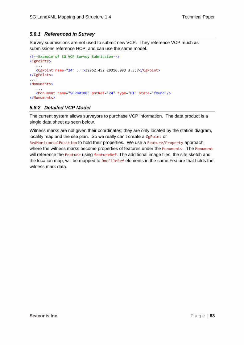
SG LandXML Mapping and Structure 1.4 Technical Paper
Seaconis Inc. P a g e | 83
5.8.1 Referenced in Survey
Survey submissions are not used to submit new VCP. They reference VCP much as
submissions reference HCP, and can use the same model.
<!--Example of SG VCP Survey Submission--> <CgPoints> ... <CgPoint name="24" ...>32962.452 29316.093 3.557</CgPoint> </CgPoints> ... <Monuments> ... <Monument name="VCP80188" pntRef="24" type="BT" state="found"/> </Monuments>
5.8.2 Detailed VCP Model
The current system allows surveyors to purchase VCP information. The data product is a
single data sheet as seen below.
Witness marks are not given their coordinates; they are only located by the station diagram,
locality map and the site plan. So we really can’t create a CgPoint or
RedHorizontalPosition to hold their properties. We use a Feature/Property approach,
where the witness marks become properties of features under the Monuments. The Monument
will reference the Feature using featureRef. The additional image files, the site sketch and
the location map, will be mapped to DocFileRef elements in the same Feature that holds the
witness mark data.
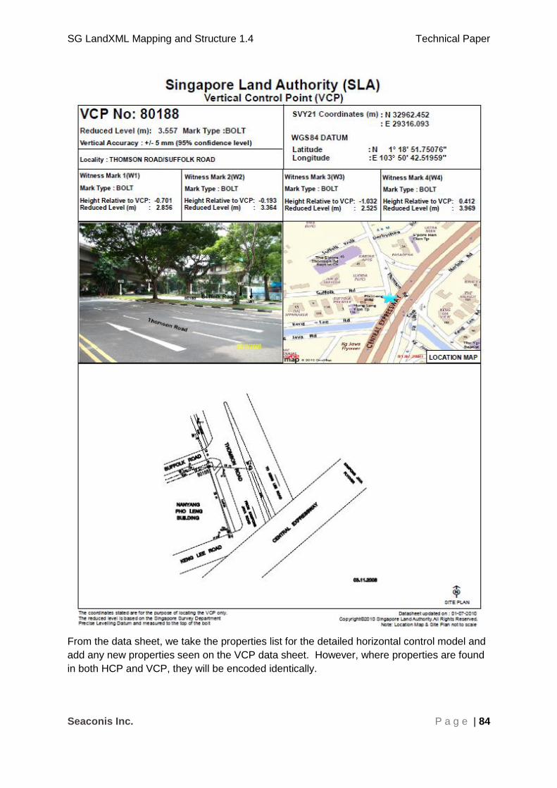
SG LandXML Mapping and Structure 1.4 Technical Paper
Seaconis Inc. P a g e | 84
From the data sheet, we take the properties list for the detailed horizontal control model and
add any new properties seen on the VCP data sheet. However, where properties are found
in both HCP and VCP, they will be encoded identically.
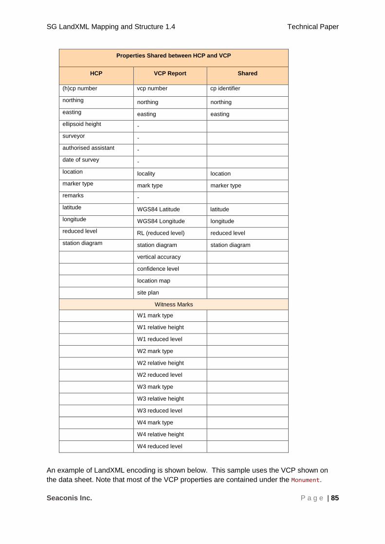
SG LandXML Mapping and Structure 1.4 Technical Paper
Seaconis Inc. P a g e | 85
Properties Shared between HCP and VCP
HCP VCP Report Shared
(h)cp number vcp number cp identifier
northing northing northing
easting easting easting
ellipsoid height -
surveyor -
authorised assistant -
date of survey -
location locality location
marker type mark type marker type
remarks -
latitude WGS84 Latitude latitude
longitude WGS84 Longitude longitude
reduced level RL (reduced level) reduced level
station diagram station diagram station diagram
vertical accuracy
confidence level
location map
site plan
Witness Marks
W1 mark type
W1 relative height
W1 reduced level
W2 mark type
W2 relative height
W2 reduced level
W3 mark type
W3 relative height
W3 reduced level
W4 mark type
W4 relative height
W4 reduced level
An example of LandXML encoding is shown below. This sample uses the VCP shown on
the data sheet. Note that most of the VCP properties are contained under the Monument.
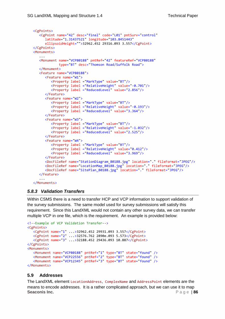
SG LandXML Mapping and Structure 1.4 Technical Paper
Seaconis Inc. P a g e | 86
<CgPoints> <CgPoint name="42" desc="final" code="L01" pntSurv="control" latitude="1.31437521" longitude="103.8451443" ellipsoidHeight="">32962.452 29316.093 3.557</CgPoint> </CgPoints> <Monuments> ... <Monument name="VCP80188" pntRef="42" featureRef="VCP80188" type="BT" desc="Thomson Road/Suffolk Road"> </Monument> <Feature name="VCP80188"> <Feature name="W1"> <Property label ="MarkType" value="BT"/> <Property label ="RelativeHeight" value="-0.701"/> <Property label ="ReducedLevel" value="2.856"/> </Feature> <Feature name="W2"> <Property label ="MarkType" value="BT"/> <Property label ="RelativeHeight" value="-0.193"/> <Property label ="ReducedLevel" value="3.364"/> </Feature> <Feature name="W3"> <Property label ="MarkType" value="BT"/> <Property label ="RelativeHeight" value="-1.032"/> <Property label ="ReducedLevel" value="2.525"/> </Feature> <Feature name="W4"> <Property label ="MarkType" value="BT"/> <Property label ="RelativeHeight" value="0.412"/> <Property label ="ReducedLevel" value="3.969"/> </Feature> <DocFileRef name="StationDiagram_80188.jpg" location="." fileFormat="JPEG"/> <DocFileRef name="LocationMap_80188.jpg" location="." fileFormat="JPEG"/> <DocFileRef name="SitePlan_80188.jpg" location="." fileFormat="JPEG"/> </Feature> ... </Monuments>
5.8.3 Validation Transfers
Within CSMS there is a need to transfer HCP and VCP information to support validation of
the survey submissions. The same model used for survey submissions will satisfy this
requirement. Since this LandXML would not contain any other survey data, we can transfer
multiple VCP in one file, which is the requirement. An example is provided below:
<!--Example of VCP Validation Transfer--> <CgPoints> <CgPoint name="1" ...>32962.452 29931.093 3.557</CgPoint> <CgPoint name="2" ...>32576.762 2890e.093 5.573</CgPoint> <CgPoint name="3" ...>32188.452 29436.093 10.887</CgPoint> </CgPoints> <Monuments> <Monument name="VCP80188" pntRef="1" type="BT" state="found" /> <Monument name="VCP22556" pntRef="2" type="BT" state="found" /> <Monument name="VCP12345" pntRef="3" type="BT" state="found" /> </Monuments>
5.9 Addresses
The LandXML element LocationAddress, ComplexName and AddressPoint elements are the
means to encode addresses. It is a rather complicated approach, but we can use it to map

SG LandXML Mapping and Structure 1.4 Technical Paper
Seaconis Inc. P a g e | 87
Singapore addresses to the LandXML standard. This table presents a mapping of the CS
Directive 4.0 address model to SG LandXML. SGDRM address model mapping is noted in
the element descriptions.
The LocationAddress itself does not allow a Feature child element, and has little
customisation facility other than repurposing of existing attributes, which are not adequate
for our needs. We therefore use the AddressPoint, which may be a child of
LocationAddress, to serve as a pointer to a Feature that contains custom properties, via its
AddressPoint@featureRef attribute. This is an unfortunate complication, but the best option
given the inflexibility of the LandXML LocationAddress definition.
Data Item Type Description LandXML
Element@attribute
Attribute/Value
House
Number
string (10) the house number
(block in CS 3.4)
LocationAddress numberFirst
Street
Name string (75) street name RoadName roadName
Level
Number
string (3) Level No e.g. 04 or 11 (If Level No is single digit, put a zero in front)
LocationAddress floorLevelNumber
Unit
Number
string (5) the unit number LocationAddress flatNumber
Postal
Code
int (6) Postal Code, if the postal code could not be found in the Singapore Post file (This field is optional)
Feature property,
referenced through
AddressPoint
featureRef.
postalCode
Address
Source
sourceType Address source, for
example IRAS
Feature property,
referenced through
AddressPoint
featureRef.
addressSource
Building
Name
string (50) Name of the
building
ComplexName desc
Building
Source
sourceType source of building
name, for example
IRAS
Feature property,
referenced through
AddressPoint
featureRef.
buildingSource
Please view the LocationAddress element attributes for SGDRM address attribute mapping.
The CS Directive address data items Address Source, Building Source and Postal Code are
referenced through a child AddressPoint to a Feature as shown below:
<LocationAddress
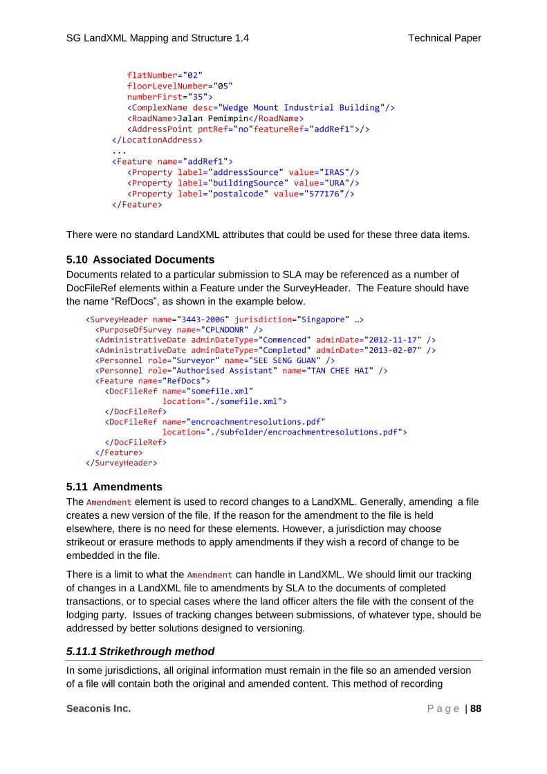
SG LandXML Mapping and Structure 1.4 Technical Paper
Seaconis Inc. P a g e | 88
flatNumber="02" floorLevelNumber="05" numberFirst="35"> <ComplexName desc="Wedge Mount Industrial Building"/> <RoadName>Jalan Pemimpin</RoadName> <AddressPoint pntRef="no"featureRef="addRef1">/> </LocationAddress> ... <Feature name="addRef1"> <Property label="addressSource" value="IRAS"/> <Property label="buildingSource" value="URA"/> <Property label="postalcode" value="577176"/> </Feature>
There were no standard LandXML attributes that could be used for these three data items.
5.10 Associated Documents
Documents related to a particular submission to SLA may be referenced as a number of
DocFileRef elements within a Feature under the SurveyHeader. The Feature should have
the name “RefDocs”, as shown in the example below.
<SurveyHeader name="3443-2006" jurisdiction="Singapore" …> <PurposeOfSurvey name="CPLNDONR" /> <AdministrativeDate adminDateType="Commenced" adminDate="2012-11-17" /> <AdministrativeDate adminDateType="Completed" adminDate="2013-02-07" /> <Personnel role="Surveyor" name="SEE SENG GUAN" /> <Personnel role="Authorised Assistant" name="TAN CHEE HAI" /> <Feature name="RefDocs"> <DocFileRef name="somefile.xml" location="./somefile.xml"> </DocFileRef> <DocFileRef name="encroachmentresolutions.pdf" location="./subfolder/encroachmentresolutions.pdf"> </DocFileRef> </Feature> </SurveyHeader>
5.11 Amendments
The Amendment element is used to record changes to a LandXML. Generally, amending a file
creates a new version of the file. If the reason for the amendment to the file is held
elsewhere, there is no need for these elements. However, a jurisdiction may choose
strikeout or erasure methods to apply amendments if they wish a record of change to be
embedded in the file.
There is a limit to what the Amendment can handle in LandXML. We should limit our tracking
of changes in a LandXML file to amendments by SLA to the documents of completed
transactions, or to special cases where the land officer alters the file with the consent of the
lodging party. Issues of tracking changes between submissions, of whatever type, should be
addressed by better solutions designed to versioning.
5.11.1 Strikethrough method
In some jurisdictions, all original information must remain in the file so an amended version
of a file will contain both the original and amended content. This method of recording

SG LandXML Mapping and Structure 1.4 Technical Paper
Seaconis Inc. P a g e | 89
amendments replicates the system of strikethrough, where original information on a paper
plan was struck out but remained readable and new information was added in a style that
could be identified as being an amendment to the plan.
Using the strikeout method, an Amendment element will contain at least one
AmendmentItem element that will have either:
1. In the case of simple deletion, an oldName attribute referencing the name of the element that was deleted
2. In the case of a simple addition, a newName attribute referencing the name of the added element
3. In the case of an amendment or replacement, an oldName attribute referencing the element with the original data and a newName attribute referencing the element with the current data.
This clearly requires all data objects to be uniquely identifiable.
Examples:
An amendment where a new element is added to the LandXML:
<Parcels> <Parcel class="final" name="MK12-12345A" area="2050.7" parcelType=”land” desc=”CP12345” parcelFormat=”standard”> <CoordGeom> ... </CoordGeom> </Parcel> </Parcels> <Amendment dealingNumber="CP12345" amendmentDate="2010-02-09" comments="Lot MK12-12345A added to plan"> <AmendmentItem elementName="Parcel" newName="MK12-12345A"/> </Amendment>
Or an amendment where an element is modified.
<CgPoints> <CgPoint name="1" desc="final" pntSurv="boundary" code="L01">36135.580 22767.794</CgPoint> </CgPoints> <Amendment dealingNumber="CP23456" amendmentDate="2010-02-09" comments="Correction to Station 1 coordinate"> <AmendmentItem elementName="CgPoint" oldName="1 " newName="1 "/> </Amendment> Or an amendment where an element is removed. <Amendment dealingNumber="CP23457" amendmentDate="2010-02-09" comments="Remove Station 1 from Plan"> <AmendmentItem elementName="CgPoint" oldName="1"/> </Amendment>
5.12 Reference Plan Areas
Alienation surveys can record reference plan areas as a listing in the SurveyHeader. These
areas can then be compared to the planned or surveyed areas. The structural encoding is as
follows:
<SurveyHeader> <Feature name="referencePlanArea">
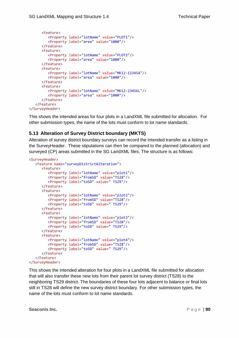
SG LandXML Mapping and Structure 1.4 Technical Paper
Seaconis Inc. P a g e | 90
<Feature> <Property label="lotName" value="PLOT1"/> <Property label="area" value="1000"/> </Feature> <Feature> <Property label="lotName" value="PLOT2"/> <Property label="area" value="1000"/> </Feature> <Feature> <Property label="lotName" value="MK12-12345A"/> <Property label="area" value="1000"/> </Feature> <Feature> <Property label="lotName" value="MK12-23456L"/> <Property label="area" value="1000"/> </Feature> </Feature> </SurveyHeader>
This shows the intended areas for four plots in a LandXML file submitted for allocation. For
other submission types, the name of the lots must conform to lot name standards.
5.13 Alteration of Survey District boundary (MKTS)
Alteration of survey district boundary surveys can record the intended transfer as a listing in
the SurveyHeader. These stipulations can then be compared to the planned (allocation) and
surveyed (CP) areas submitted in the SG LandXML files. The structure is as follows:
<SurveyHeader> <Feature name="surveyDistrictAlteration"> <Feature> <Property label="lotName" value="plot1"/> <Property label="fromSD" value="TS28"/> <Property label="toSD" value=" TS29"/> </Feature> <Feature> <Property label="lotName" value="plot2"/> <Property label="fromSD" value="TS28"/> <Property label="toSD" value=" TS29"/> </Feature> <Feature> <Property label="lotName" value="plot3"/> <Property label="fromSD" value="TS28"/> <Property label="toSD" value=" TS29"/> </Feature> <Feature> <Property label="lotName" value="plot4"/> <Property label="fromSD" value="TS28"/> <Property label="toSD" value=" TS29"/> </Feature> </Feature> </SurveyHeader>
This shows the intended alteration for four plots in a LandXML file submitted for allocation
that will also transfer these new lots from their parent lot survey district (TS28) to the
neighboring TS29 district. The boundaries of these four lots adjacent to balance or final lots
still in TS28 will define the new survey district boundary. For other submission types, the
name of the lots must conform to lot name standards.

SG LandXML Mapping and Structure 1.4 Technical Paper
Seaconis Inc. P a g e | 91
5.14 Elevations
Elevation lists or tables are often used to provide a single source for elevations used by a
survey or spatial data set. This is more efficient than including elevations values in every
single point, especially where proper 3D geometries are right angle extensions to a 2D
geometry ( right-volume or extruded are two terms for this shape). In SGLX, elevation lists
have a single standard Feature/Property construct and can be used in multiple contexts.
For instance, a set of elevations for a land survey and a separate set of elevations for a
building.
The structure of the Elevations construct is as shown below. Elevations are identified by
unique strings; they need not be sequentially numbered, nor in a specific order. Elevation
values are to be in metres from Singapore Height Datum (SHD) datum. Note that these level
elevations may be calculated, as inaccessible boundaries within physical structures. For
instance, an elevation halfway between the apparent floor of an upper strata lot and the
apparent ceiling of the lower strata lot.
<SurveyHeader> ... <Feature name="Elevations"> <Property label="level 1" value="9.5"/> <Property label="level 2" value="13.5"/> <Property label="level 3" value="17.34"/> <Property label="level 3 false ceiling" value="19.0"/> <Property label="level 4" value="19.34"/> </Feature> </SurveyHeader>
For elevations referenced by land surveys, including airspace and subterranean lots, the
construct is placed as a child of the SurveyHeader, as only one set of level elevations would
be necessary in a single survey. Elevations used for defining strata objects, discussed later
in this document, will typically require an elevations structure as a child of the Building (a
parcel type). Therefore, when multiple buildings are submitted, each building would have its
own elevation list.
References to elevations are fundamental to many cadastral features, and the context of the
referenced must be correct. Ensure that you scope the reference to the correct elevations
list.
Upper and lower elevations are a property of many cadastral objects. Therefore, a construct
that contains a pair of elevation references is quite useful, and is shown below. For a Parcel
element, the parcelFormat attribute must be set to indicate the lot is defined as a right-
volume (Parcel@parcelFormat=”extruded”).
<Feature name="ElevRefPair"> <Property label="lower" value="level 3"/> <Property label="upper" value="level 3 false ceiling"/> </Feature>

SG LandXML Mapping and Structure 1.4 Technical Paper
Seaconis Inc. P a g e | 92
6 Strata Plan Structures
This section discusses the use of LandXML elements to encode strata title plans, buildings,
strata and accessory lots, building outlines, level outlines, typical stories, supporting parcel
types, and occupations.
The goal is to create a complete strata data transfer format model which supports efficient
encoding of potentially extensive and complex, yet repetitive data. Support for typical
storeys allows a single set of objects to represent multiple storeys or levels within the
building. Software developed to load data from the XML can instantiate the models or parts
of the models as necessary. For instance, if there are 20 storeys derived from a single
typical storey, and there is a need to analyse the strata lots for encroachment, then analysis
need only be done on the typical storey virtual parcels. So abstraction is more than a data
transfer efficiency.
Strata properties and objects:
1. STP metadata.
2. CPST metadata.
3. Buildings.
4. Levels and level outlines.
5. Typical Storey1.
6. Virtual Parcels.
7. Strata lots.
8. Accessory lots.
9. Common Properties.
10. Voids.
11. Occupations.
12. Provisional strata lots.
Many strata entities are represented by the Parcel element. They are associated a specific
building and level using the buildingNo and buildingLevelNo Parcel attributes.
6.1 STP Properties
The Strata Title Plan (STP) is required when there are three or more strata lots involved in a
new development, or if the existing strata lot has an STP number assigned. The STP
number identifies the submissions as part of a strata project. It is encoded in a Feature
construct under the SurveyHeader. The LandLotNumber value in the construct lists all land lots
used in the Strata Development.
1 CS Directive v4.0 uses the term storey where LandXML uses the term level. At times, we
adhered to the LandXML term “level”, but more often employ “storey” in descriptions and
names. They both mean the same thing.

SG LandXML Mapping and Structure 1.4 Technical Paper
Seaconis Inc. P a g e | 93
<SurveyHeader> ... <Feature name="STP"> <Property label="STPNumber" value="STP1234"/> <Property label="LandLotNumber" value="MK18-40000A, MK18-40001B,MK18-40002C"/> </Feature> </SurveyHeader>
6.2 CPST Properties
At the allocation of Strata lot numbers, it is possible that SLA may not require the surveyor to
submit the geometry of planned strata lots. Instead, the surveyor must include the following:
the number of strata lot numbers, the number of accessory lot numbers and the number of
strata provisional lot numbers. This data is encoded in a separate feature under the
SurveyHeader as shown below.
The CPST feature is required for all strata surveys to indicate the strata allocation lot count
and the land lots used.
<SurveyHeader> ... <Feature name="CPST"> <Property label="LandLotNumber" value="MK18-40000A"></Property> <Property label="StrataLotCount" value="256"></Property> <Property label="AccessLotCount" value="120"></Property> <Property label="ProvisionalLotCount" value="10"></Property> </Feature>
</SurveyHeader>
6.3 Use of Parcel Element
The LandXML parcel element is heavily used for modelling strata objects. Firstly, most
strata object are geometric polygons. LandXML parcels also have one of the more complete
attribution sets of all LandXML elements. Strata parcel types are configured with extensions
to the jurisdictional enumerations for parcel attributes.
The Parcel element has several attributes and child elements of use in many of the strata
plan objects:
1. name – depends on role
2. area – stated area to 1 square meter, required depending on role
3. volume – stated volume, required depending on role
4. parcelType – depends on role
5. class- depends on role
6. parcelFormat = ”extruded”, building is “standard”
7. buildingNo = building number
8. buildingLevelNo = level number
9. CoordGeom – various geometry allowed
10. LocationAddress – reduced to flatNo for most strata lots

SG LandXML Mapping and Structure 1.4 Technical Paper
Seaconis Inc. P a g e | 94
6.4 The Third Dimension
In our SGLX model, strata objects are inherently three dimensional. There are two basic
methods by which elevations are conveyed in the SGLX: geometric element content that
includes all three components (northing easting elevation), and a data normalization
approach. The normalization employs a summary, unique, list of elevations that may then
be referenced. In strata, these references return the lower and upper vertical extents of right
shapes, which can then be extruded from the 2D parcel geometry. In this strata section, we
focus on the second method.
Any of the strata parcel type may have an ElevRefPair construct which holds these upper
and lower elevations for the right shape (extrusion) of the parcel. This can be used to set
the upper and lower elevations of any parcel, thereby overriding the elevations of the Level
(see 6.5.4 for discussion.)
Regardless if the elevations references are transferred via the ElevRefPair of the level, or
an ElevRefPair in the parcel itself, the parcelFormat should be extruded.
SGLX support for fully three dimensional geometry is forthcoming. However, full 3D parcels
should coexist with right-volume parcels in the same SGLX submission..
6.5 Building
The building is the top object in the strata model. Yet, there is no specific element in
LandXML for the representation of a building, and buildings are not containers of other
objects.
Buildings are encoded as a Parcel element to represent all building meta-information,
including a “greatest extent” (2D) outline. Any number of buildings may be in the
submission.
It is probably best to think of the building and level (introduced next) as organizational
notions in the SGLX. It is really the lots that are important, and in cadastre in general.
Mostly, we use the building number and the level number references on the strata parcels to
query, map and analyse the strata data.
6.5.1 Land Lot
A building must rest upon one or more land lots. We use a feature construct to convey the
lot name, or names, of the land parcels. Multiple land lots are encoded using comma
separated values.
<Feature name="LandLot"> <Property label="name" value="TS30-00385M,TS30-00386X "/> </Feature>
6.5.2 Address
LocationAddress is be used to hold the building address in Singapore, following the address
scheme described elsewhere in the structural discussions. The LocationAddress should be
held by the building parcel.
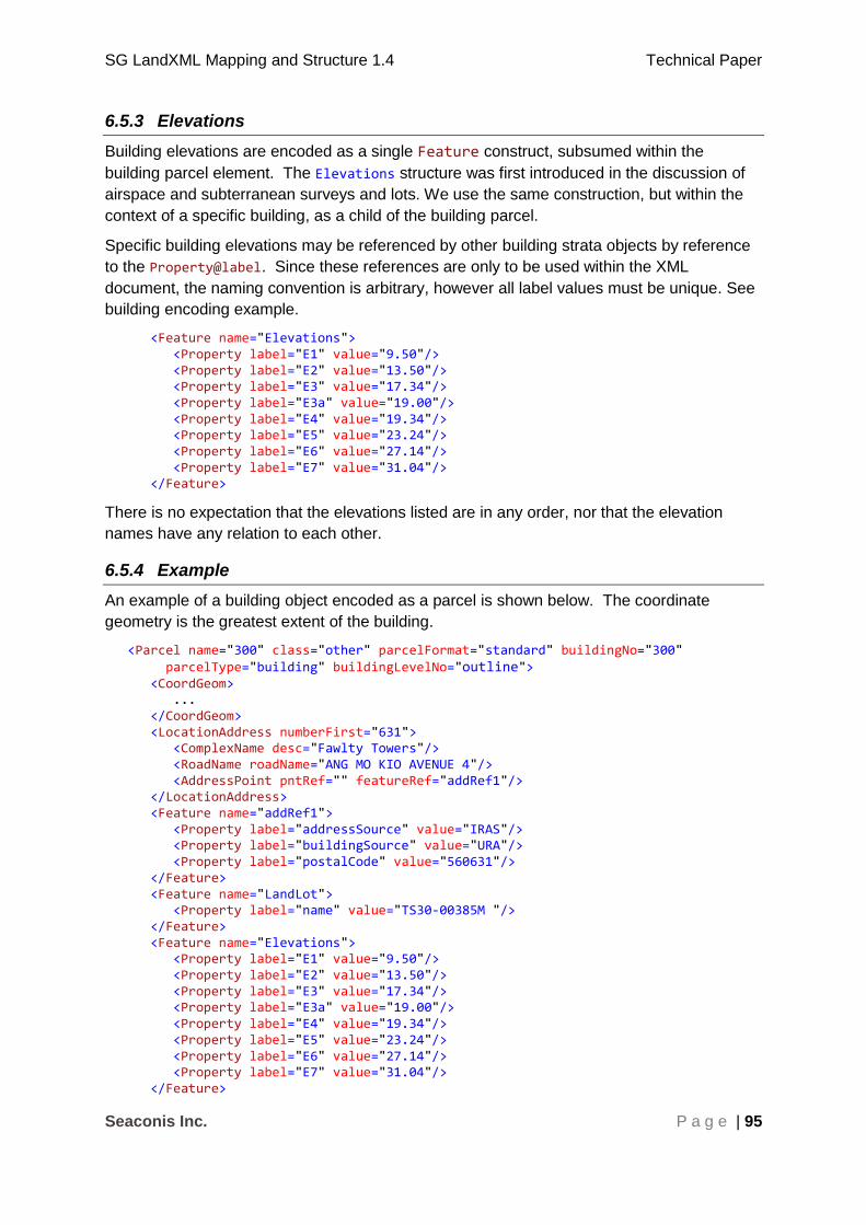
SG LandXML Mapping and Structure 1.4 Technical Paper
Seaconis Inc. P a g e | 95
6.5.3 Elevations
Building elevations are encoded as a single Feature construct, subsumed within the
building parcel element. The Elevations structure was first introduced in the discussion of
airspace and subterranean surveys and lots. We use the same construction, but within the
context of a specific building, as a child of the building parcel.
Specific building elevations may be referenced by other building strata objects by reference
to the Property@label. Since these references are only to be used within the XML
document, the naming convention is arbitrary, however all label values must be unique. See
building encoding example.
<Feature name="Elevations"> <Property label="E1" value="9.50"/> <Property label="E2" value="13.50"/> <Property label="E3" value="17.34"/> <Property label="E3a" value="19.00"/> <Property label="E4" value="19.34"/> <Property label="E5" value="23.24"/> <Property label="E6" value="27.14"/> <Property label="E7" value="31.04"/> </Feature>
There is no expectation that the elevations listed are in any order, nor that the elevation
names have any relation to each other.
6.5.4 Example
An example of a building object encoded as a parcel is shown below. The coordinate
geometry is the greatest extent of the building.
<Parcel name="300" class="other" parcelFormat="standard" buildingNo="300" parcelType="building" buildingLevelNo="outline"> <CoordGeom> ... </CoordGeom> <LocationAddress numberFirst="631"> <ComplexName desc="Fawlty Towers"/> <RoadName roadName="ANG MO KIO AVENUE 4"/> <AddressPoint pntRef="" featureRef="addRef1"/> </LocationAddress> <Feature name="addRef1"> <Property label="addressSource" value="IRAS"/> <Property label="buildingSource" value="URA"/> <Property label="postalCode" value="560631"/> </Feature> <Feature name="LandLot"> <Property label="name" value="TS30-00385M "/> </Feature> <Feature name="Elevations"> <Property label="E1" value="9.50"/> <Property label="E2" value="13.50"/> <Property label="E3" value="17.34"/> <Property label="E3a" value="19.00"/> <Property label="E4" value="19.34"/> <Property label="E5" value="23.24"/> <Property label="E6" value="27.14"/> <Property label="E7" value="31.04"/> </Feature>

SG LandXML Mapping and Structure 1.4 Technical Paper
Seaconis Inc. P a g e | 96
</Parcel>
Note: parcelFormat is set as “standard” rather than “extruded” as there are no elevations set
for the building itself.
Note: buildingNo will be used to group other LandXML elements to this building.
Note: buildingLevelNo is alphanumeric.
6.6 Level
Conceptually, a level is an organizational category of strata objects in a building. Yet, like
the building, it is not a container of these objects, and there is no composite relationship.
Rather, the level holds information and relationships that are common to the cadastral
objects that are associated to the level by their own properties.
A level is encoded as a Parcel element; whose geometry represents the exterior extent of
the level. Strata lots, accessory lots, common properties, void spaces, and void areas
associate with one and only one Level by their buildingLevelNo attribute. The level does
NOT have a Parcels element referencing the lots. Levels may also contain references to
occupations which represent physical features.
6.6.1 Attributes
Levels and level outlines are modelled as a Parcel in the LandXML file.
Set:
1. name = ”any name” (unique building level name)
2. parcelType = ”level”
3. class = ”other”
4. parcelFormat = ”extruded” (has ElevRefPair)
5. buildingNo = building number
6. buildingLevelNo = level number
A level Parcel element is identified by parcelType=”level”. A level must be unique in the
building, that is, only one level in a building may have the same buildingLevelNo, which
must be unique within the building. However, the buildingLevelNo is a string value, and the
levels are not required to indicate any ordering.
6.6.2 Name
Parcels may follow any naming scheme. The buildingNo and buildingLevelNo values
provide a combined unique identifier for processing. Therefore, the name may be used for
presentation and cartographic purposes.
6.6.3 Coordinate Geometry
Level geometry encoding is not constrained to the degree of land parcels, at least in the near
future. IrregularLine geometry using PntList2D is expected to be common, but any
supported CoordGeom is allowed.

SG LandXML Mapping and Structure 1.4 Technical Paper
Seaconis Inc. P a g e | 97
6.6.4 Elevation References
Each level must be associated with building elevations corresponding to its lower and upper
vertical extent. These are encoded as ElevRefPair constructs.
<Feature name="ElevRefPair"> <Property label="lower" value="E3"/> <Property label="upper" value="E3a"/> </Feature>
The elevation references have several purposes, and work in combination with elevations
set at the parcel level.
For levels that have consistent lower and upper profiles, the level references are simply the
lower and upper elevations of all the associated cadastral parcels on that level.
For more complex situations, some or all of the associated parcels may have their own
ElevRefPair which then overrides the elevations indicated in the Level parcel. This is an
important refinement in the strata model, allowing more adaptive modelling.
For example, some levels are not level. A section of the storey may step down a half meter,
and yet maintain the upper elevation, or the opposite, or both may vary independently.
Perhaps a topmost level has a consistent lower elevation, but a completely irregular upper
elevation. As long as these changes occur at lot boundaries, the override functionality can
model them.
Also, this functionality provides an approach for a more complex vertical hierarchy of lots
within lots. For example, accessory lots or voids which do not occupy the full level height.
So, where needed, the override in affected parcels can deal with a greater variety of building
designs, and still provide the simplicity of centralized elevation collections. In essence, we
have the flexibility to model simple buildings simply, and then move along a gradient of more
complex situations by applying lot elevations directly only where needed.
This approach is also able to integrate with parcels that are defined by more complex full 3D
volume geometries.
6.6.5 Occupation References
Levels can reference occupations by two methods, by reference to the occupation name or
to the occupation group.
References are established using a feature construct, where the property label is the
reference type and the value is the reference value. The astute reader will realize that this
can be used to reference occupations created for a specific level, or for the generalized case
of the typical storey.
This example shows the feature-property used to reference occupations (not shown).
<Parcel name="L5" class="other" parcelFormat="standard" buildingNo="500" parcelType="level" buildingLevelNo="5"> <CoordGeom> ... </CoordGeom> <Feature name="details"> <Property label="group" value="UpperFloorOuterWalls"/> <Property label="occName" value="SouthElevatorWall"/>
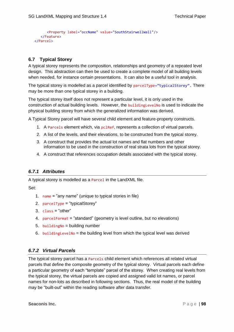
SG LandXML Mapping and Structure 1.4 Technical Paper
Seaconis Inc. P a g e | 98
<Property label="occName" value="SouthStairwellWall"/> </Feature> </Parcel>
6.7 Typical Storey
A typical storey represents the composition, relationships and geometry of a repeated level
design. This abstraction can then be used to create a complete model of all building levels
when needed, for instance certain presentations. It can also be a useful tool in analysis.
The typical storey is modelled as a parcel identified by parcelType=”typicalStorey”. There
may be more than one typical storey in a building.
The typical storey itself does not represent a particular level, it is only used in the
construction of actual building levels. However, the buildingLevelNo is used to indicate the
physical building storey from which the generalized information was derived.
A Typical Storey parcel will have several child element and feature-property constructs.
1. A Parcels element which, via pclRef, represents a collection of virtual parcels.
2. A list of the levels, and their elevations, to be constructed from the typical storey.
3. A construct that provides the actual lot names and flat numbers and other information to be used in the construction of real strata lots from the typical storey.
4. A construct that references occupation details associated with the typical storey.
6.7.1 Attributes
A typical storey is modelled as a Parcel in the LandXML file.
Set:
1. name = ”any name” (unique to typical stories in file)
2. parcelType = ”typicalStorey”
3. class = ”other”
4. parcelFormat = ”standard” (geometry is level outline, but no elevations)
5. buildingNo = building number
6. buildingLevelNo = the building level from which the typical level was derived
6.7.2 Virtual Parcels
The typical storey parcel has a Parcels child element which references all related virtual
parcels that define the composite geometry of the typical storey. Virtual parcels each define
a particular geometry of each “template” parcel of the storey. When creating real levels from
the typical storey, the virtual parcels are copied and assigned valid lot names, or parcel
names for non-lots as described in following sections. Thus, the real model of the building
may be “built-out” within the reading software after data transfer.

SG LandXML Mapping and Structure 1.4 Technical Paper
Seaconis Inc. P a g e | 99
Virtual Parcels are identified by the parcelType of "virtual". The different virtual parcels
within a building are identified by name convention. Name convention templates are a
capitalized character followed by a monotonically increasing serial number starting with 1. In
the list below, "x" is the number.
"Ux" virtual strata lots
"Ax" virtual accessory lots
"Cx" virtual common properties (realised parcels will be "CAx")
"Vx" virtual void areas (realised parcels will be "VAx")
When realised, all parcels will have their parcelType set to the appropriate enumeration
item, and the name set to a true name for lots, and by some convention for non-lot parcels.
In effect, non-lot parcels would not need to be realised. Since all island-type enclosed
parcels are referenced in the Parcels element of a lot, with the individual Parcels referenced
by pclRef, there is no need for more than one copy of a non-lot parcel in a realised level.
This is the discretion of any reading software.
Occupations are referenced, and can be referenced by any realised level. As with non-lot
parcels, occupations could be copied to realised levels if necessary.
6.7.3 Level Values
To build-out levels from a typical storey, we need the names of the levels to create, and their
elevation references. The LevelValues construct is used to provide this information.
<Feature name="LevelValues"> <Feature name="300-L3"> <Feature name="ElevRefPair"> <Property label="lower" value="E3"/> <Property label="upper" value="E4"/> </Feature> </Feature> <Feature name="300-L4"> <Feature name="ElevRefPair"> <Property label="lower" value="E4"/> <Property label="upper" value="E5"/> </Feature> </Feature> ...
</Feature>
The hierarchical structure can be easily extended if additional level property information is needed.
6.7.4 Parcel Values
When we create a level from a typical storey, we need to copy virtual parcels and update
their properties with specific lot data. We use a hierarchical Feature construct to encode the
attributes needed to instantiate the lots. Some properties are in the virtual lot itself;
geometry, area, and any other property that is common between the levels. The key
properties to transfer to the created lot are the lot name and flat number. An accessory lot
will also require lot names needed to establish the “appurtenant to” relationship.

SG LandXML Mapping and Structure 1.4 Technical Paper
Seaconis Inc. P a g e | 100
This is an example of the ParcelValues structure for a single level.
<!-- Lot names and flat numbers for level 3--> <Feature name="ParcelValues"> <Feature name="300-L3"> <Feature name="U1"> <Property label="lotName" value="MK18-U300001A"/> <Property label="flatNo" value="301"/> </Feature> <Feature name="U2"> <Property label="lotName" value="MK18-U300002F"/> <Property label="flatNo" value="302"/> </Feature> <Feature name="U3"> <Property label="lotName" value="MK18-U300003L"/> <Property label="flatNo" value="303"/> </Feature> <Feature name="U4"> <Property label="lotName" value="MK18-U300004J"/> <Property label="flatNo" value="304"/> </Feature> <Feature name="U5"> <Property label="lotName" value="MK18-U300005T"/> <Property label="flatNo" value="305"/> </Feature> <Feature name="A1"> <Property label="lotName" value="MK18-A3001N"/> <Property label="appTo" value="MK18-U300005T"/> <Property label="flatNo" value="S-305"/> </Feature> <Feature name="C1"> <Property label="lotName" value="CA1"/> </Feature> </Feature> </Feature>
This example holds data for five strata lots, one accessory lot, and a common property for the 300-L3 level. This hierarchical structure can be easily extended if additional properties are needed. Note that the accessory lot is appurtenant to the strata lot created from virtual lot U5.
6.7.5 Typical Lot
Any virtual parcel can be denoted as a typical lot. A typical strata lot is used to show the
general characteristics and properties of a commonly occurring strata lot within the building.
There may be many virtual parcels within a building that are similar to a typical strata lot,
with the exception that the geometry is transposed. For instance, there may be 10 lots of the
same type along the south side of a building level, arranged from the west side to the east.
This same arrangement of typical lot may be repeated on the north side of the floor, and
across many floors.
The typical lot has little value in the SGLX transfer specification, but it may have value as an
encapsulation of the standard properties of a type of repeated strata lot. In this sense. It is a
generalisation. There may be several typical lots, and so their names should be unique.
Any virtual parcel can be flagged as a typical lot by the inclusion of the following feature-
property. The Feature name must be “TypicalLot”, with a unique name as the property
value.
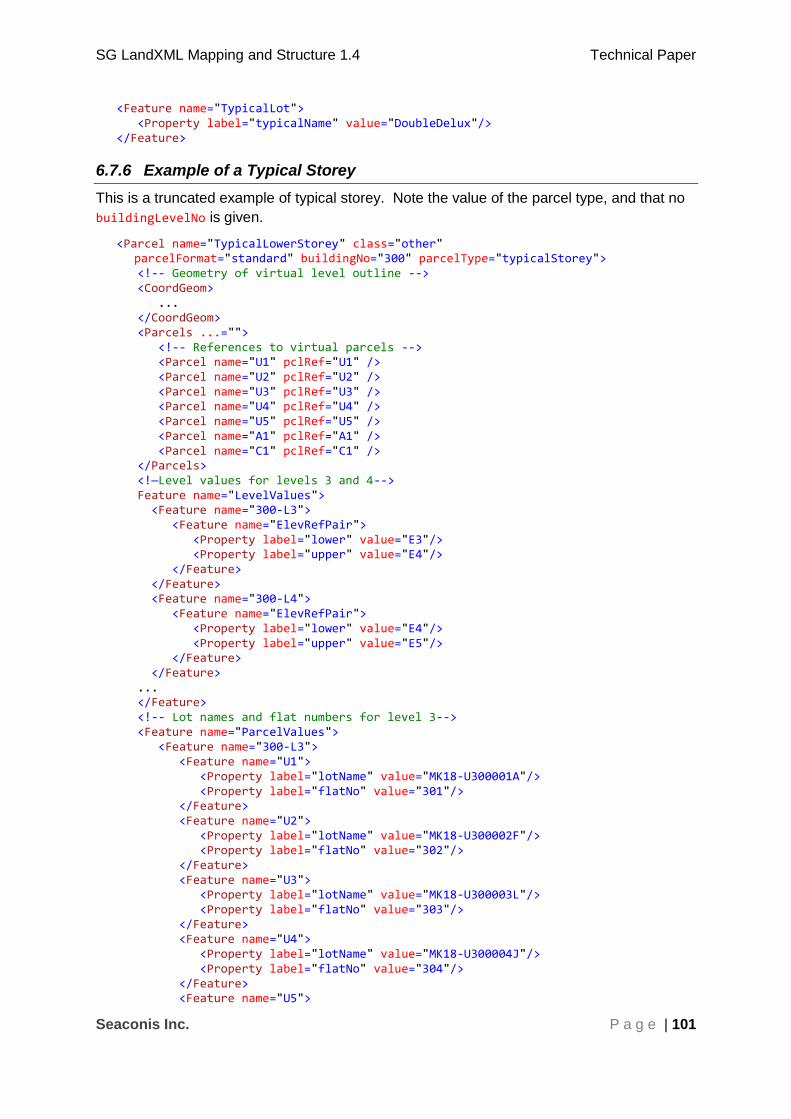
SG LandXML Mapping and Structure 1.4 Technical Paper
Seaconis Inc. P a g e | 101
<Feature name="TypicalLot"> <Property label="typicalName" value="DoubleDelux"/> </Feature>
6.7.6 Example of a Typical Storey
This is a truncated example of typical storey. Note the value of the parcel type, and that no
buildingLevelNo is given.
<Parcel name="TypicalLowerStorey" class="other" parcelFormat="standard" buildingNo="300" parcelType="typicalStorey">
<!-- Geometry of virtual level outline --> <CoordGeom> ... </CoordGeom> <Parcels ...=""> <!-- References to virtual parcels --> <Parcel name="U1" pclRef="U1" /> <Parcel name="U2" pclRef="U2" /> <Parcel name="U3" pclRef="U3" /> <Parcel name="U4" pclRef="U4" /> <Parcel name="U5" pclRef="U5" /> <Parcel name="A1" pclRef="A1" /> <Parcel name="C1" pclRef="C1" /> </Parcels> <!—Level values for levels 3 and 4--> Feature name="LevelValues"> <Feature name="300-L3"> <Feature name="ElevRefPair"> <Property label="lower" value="E3"/> <Property label="upper" value="E4"/> </Feature> </Feature> <Feature name="300-L4"> <Feature name="ElevRefPair"> <Property label="lower" value="E4"/> <Property label="upper" value="E5"/> </Feature> </Feature> ... </Feature> <!-- Lot names and flat numbers for level 3--> <Feature name="ParcelValues"> <Feature name="300-L3"> <Feature name="U1"> <Property label="lotName" value="MK18-U300001A"/> <Property label="flatNo" value="301"/> </Feature> <Feature name="U2"> <Property label="lotName" value="MK18-U300002F"/> <Property label="flatNo" value="302"/> </Feature> <Feature name="U3"> <Property label="lotName" value="MK18-U300003L"/> <Property label="flatNo" value="303"/> </Feature> <Feature name="U4"> <Property label="lotName" value="MK18-U300004J"/> <Property label="flatNo" value="304"/> </Feature> <Feature name="U5">
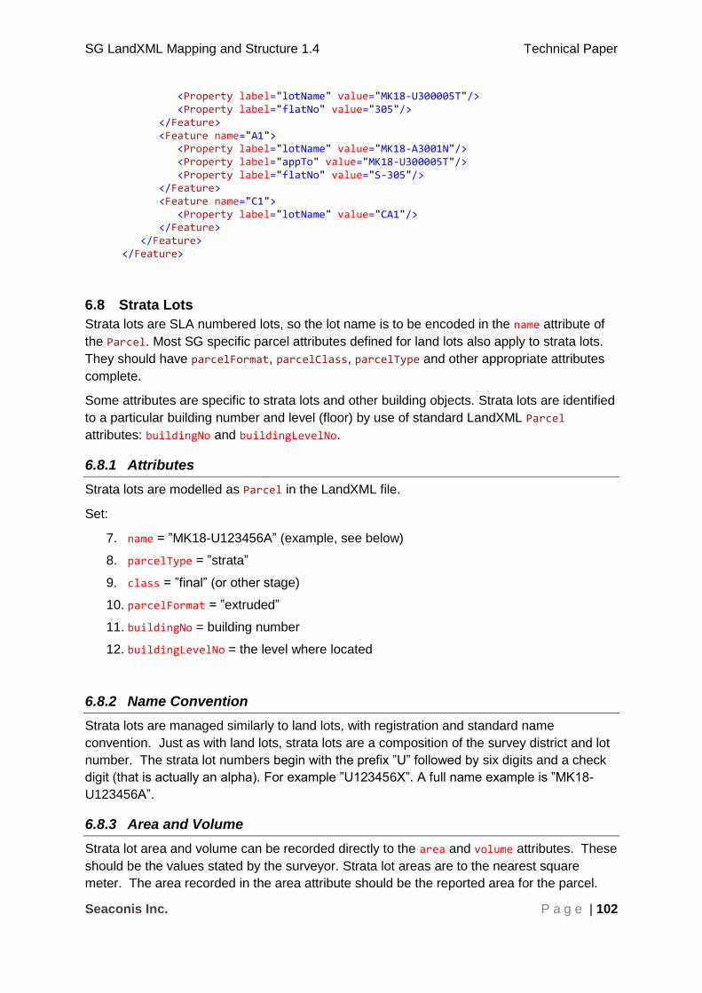
SG LandXML Mapping and Structure 1.4 Technical Paper
Seaconis Inc. P a g e | 102
<Property label="lotName" value="MK18-U300005T"/> <Property label="flatNo" value="305"/> </Feature> <Feature name="A1"> <Property label="lotName" value="MK18-A3001N"/> <Property label="appTo" value="MK18-U300005T"/> <Property label="flatNo" value="S-305"/> </Feature> <Feature name="C1"> <Property label="lotName" value="CA1"/> </Feature> </Feature> </Feature>
6.8 Strata Lots
Strata lots are SLA numbered lots, so the lot name is to be encoded in the name attribute of
the Parcel. Most SG specific parcel attributes defined for land lots also apply to strata lots.
They should have parcelFormat, parcelClass, parcelType and other appropriate attributes
complete.
Some attributes are specific to strata lots and other building objects. Strata lots are identified
to a particular building number and level (floor) by use of standard LandXML Parcel
attributes: buildingNo and buildingLevelNo.
6.8.1 Attributes
Strata lots are modelled as Parcel in the LandXML file.
Set:
7. name = ”MK18-U123456A” (example, see below)
8. parcelType = ”strata”
9. class = ”final” (or other stage)
10. parcelFormat = ”extruded”
11. buildingNo = building number
12. buildingLevelNo = the level where located
6.8.2 Name Convention
Strata lots are managed similarly to land lots, with registration and standard name
convention. Just as with land lots, strata lots are a composition of the survey district and lot
number. The strata lot numbers begin with the prefix ”U” followed by six digits and a check
digit (that is actually an alpha). For example ”U123456X”. A full name example is ”MK18-
U123456A”.
6.8.3 Area and Volume
Strata lot area and volume can be recorded directly to the area and volume attributes. These
should be the values stated by the surveyor. Strata lot areas are to the nearest square
meter. The area recorded in the area attribute should be the reported area for the parcel.
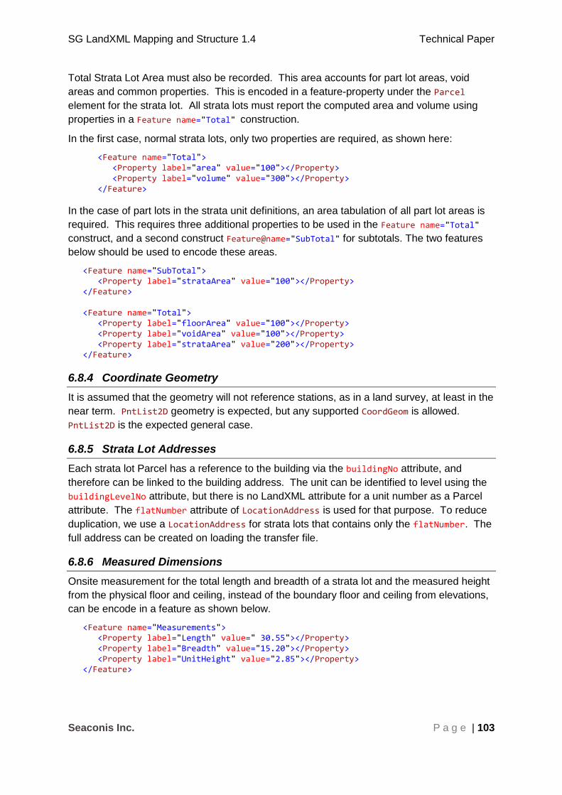
SG LandXML Mapping and Structure 1.4 Technical Paper
Seaconis Inc. P a g e | 103
Total Strata Lot Area must also be recorded. This area accounts for part lot areas, void
areas and common properties. This is encoded in a feature-property under the Parcel
element for the strata lot. All strata lots must report the computed area and volume using
properties in a Feature name="Total" construction.
In the first case, normal strata lots, only two properties are required, as shown here:
<Feature name="Total"> <Property label="area" value="100"></Property> <Property label="volume" value="300"></Property> </Feature>
In the case of part lots in the strata unit definitions, an area tabulation of all part lot areas is
required. This requires three additional properties to be used in the Feature name="Total"
construct, and a second construct Feature@name="SubTotal" for subtotals. The two features
below should be used to encode these areas.
<Feature name="SubTotal"> <Property label="strataArea" value="100"></Property> </Feature> <Feature name="Total"> <Property label="floorArea" value="100"></Property> <Property label="voidArea" value="100"></Property> <Property label="strataArea" value="200"></Property> </Feature>
6.8.4 Coordinate Geometry
It is assumed that the geometry will not reference stations, as in a land survey, at least in the
near term. PntList2D geometry is expected, but any supported CoordGeom is allowed.
PntList2D is the expected general case.
6.8.5 Strata Lot Addresses
Each strata lot Parcel has a reference to the building via the buildingNo attribute, and
therefore can be linked to the building address. The unit can be identified to level using the
buildingLevelNo attribute, but there is no LandXML attribute for a unit number as a Parcel
attribute. The flatNumber attribute of LocationAddress is used for that purpose. To reduce
duplication, we use a LocationAddress for strata lots that contains only the flatNumber. The
full address can be created on loading the transfer file.
6.8.6 Measured Dimensions
Onsite measurement for the total length and breadth of a strata lot and the measured height
from the physical floor and ceiling, instead of the boundary floor and ceiling from elevations,
can be encode in a feature as shown below.
<Feature name="Measurements"> <Property label="Length" value=" 30.55"></Property> <Property label="Breadth" value="15.20"></Property> <Property label="UnitHeight" value="2.85"></Property> </Feature>

SG LandXML Mapping and Structure 1.4 Technical Paper
Seaconis Inc. P a g e | 104
6.8.7 Relationships to Other Parcels
A single strata lot parcel may have complex relationships to other parcels. Given the many
to many relationships between strata lots and accessory lots, the relation is encoded only in
the accessory lot, not in the strata lot. See that section for more discussion and instructions.
A strata lot may enclose void areas, common properties, or even another strata lot. Spatial
relationships of this kind are encoded much the same as island parcels in land parcels. The
strata parcel may have a nested Parcels element containing one or more Parcel elements
thus establishing the relationship. These nested Parcel elements do not include full
attribution and geometry, but use pclRef to point to the full Parcel encoding at the same
hierarchical level as the strata lot.
6.8.8 Example
This example of a strata lot shows the most common attributes and properties. Note that
location address is compiled from the flatNumber and the buildingLevelNo; the rest of the
address is linked via buildingNo.
<Parcel name="MK18-U123456A" desc="ST12345" area="314" class="final" parcelFormat="extruded" parcelType="strata" buildingNo="300" buildingLevelNo="9"> <CoordGeom> ... </CoordGeom> <LocationAddress flatNumber="906"/>
<Feature name="Measurements"> <Property label="Length" value=" 30.55"></Property> <Property label="Breadth" value="15.20"></Property> <Property label="UnitHeight" value="2.85"></Property> </Feature> </Parcel>
6.9 Accessory Lots
Accessory lots are lots (spatial units) contained within buildings, appurtenant to a strata lot,
and are encoded as LandXML Parcel elements.
6.9.1 Attributes
Accessory lots are modelled as Parcels in the LandXML file.
Set:
1. name = ” MK18-A1234N”, for example (see below)
2. parcelType = ”accessory”
3. class = ”final” (or other stage)
4. parcelFormat = ” extruded”
5. buildingNo = building number
6. buildingLevelNo = the level where located
6.9.2 Name Convention
Accessory lots are managed similarly to land lots, with registration and standard name
convention. Just as with land lots, accessory lots are a composition of the survey district
and lot number. The accessory lot numbers begin with the prefix ”A” followed by four digits

SG LandXML Mapping and Structure 1.4 Technical Paper
Seaconis Inc. P a g e | 105
and a check digit (that is actually an alpha). For example, ”A1234X”, and a full name
example, ”MK18-A1234N”.
6.9.3 Area and Volume
Accessory lot area and volume can be recorded directly to the area and volume attributes.
These should be the values stated by the surveyor.
6.9.4 Coordinate Geometry
It is assumed that the geometry will not reference stations, as in a land survey, at least in the
near term. Point2D geometry is expected, but any supported CoordGeom is allowed.
PntList2D is the expected general case.
6.9.5 Relationship to Strata Lot(s)
There is an additional aggregation relationship to one or more accessory lots. That is, a
strata lot may have one or more associated accessory lots. The accessory lots are
appurtenant to the strata lot, and cannot be sold, transferred or modified independently.
They are most often parking or storage spaces. An accessory lot can be apportioned
between strata lots. In addition, an accessory lot may have more than one associated strata
lot.
A many-to-many relationship exists between strata lots and accessory lots.
This means that use of the pclRef attribute of the Parcel element is not sufficient for
encoding this relationship. It has the type parcelNameRef which is to be a single parcel name
reference.
We use Feature/Property encoding in all cases. To simplify, we can:
1. Encode relationship only in the accessory lot.
2. Use multiple instances of Property for each owner parcel of an accessory lot.
3. Feature@name=“AppurtenantTo”
4. Property@label=”pclRef”
5. Property@value=”the pclRef value”
6. On loading all accessory lots, the many-to-many relationships can be established in the reading software.
The feature-property structure is within the accessory lot Parcel element. The example
shows an accessory lot owned by two strata lots.
6.9.6 Example
This example shows an accessory lot with typical values, but two strata lot references.
<Parcel name="TS12-A4356Y" desc="ST12345" area="8" class="final" parcelFormat="extruded" parcelType="accessory" buildingNo="300" buildingLevelNo="-3"> <CoordGeom> ... </CoordGeom> <Feature name="AppurtenantTo"> <Property label="pclRef" value="TS12-U543223F"></Property> <Property label="pclRef" value="TS12-U543212A"></Property>

SG LandXML Mapping and Structure 1.4 Technical Paper
Seaconis Inc. P a g e | 106
</Feature> </Parcel>
6.10 Common Properties
Common properties are not registered or tracked by SLA as lots, yet are an important
concept for building representation and are shown on plan drawings. They serve as
important adjacency and continuity checks to the layouts of a building level during digital
validations. Common properties are encoded as Parcels.
6.10.1 Attributes
Common properties are modelled as Parcels in the LandXML file. Common properties are
not registered or tracked by SLA, so they do not need to follow the rules of registered lots.
Set:
1. name = ” CAxxxx” (see below)
2. parcelType = ”common”
3. class = ”reference”
4. parcelFormat = ”extruded”
5. buildingNo = building number
6. buildingLevelNo = the level where located
6.10.2 Name Convention
Preparation of the submission must follow a naming convention that CSMS software can use
to correctly identify these areas. The convention is ”CAxxxx” where the x values are a
number series assigned by the surveyor and unique to the submission file. There is no
survey district part in the name. The buildingNo, buildingLevelNo are to be used to locate
the common area to the correct building and floor.
6.10.3 Area and Volume
Area of common property is needed only when the common property is used for
amalgamation in the Get Lot Number submission as the common property is yet to assign a
lot number to it. Area can be recorded directly to the area attribute. It should be the value
stated by the surveyor. Volume is not needed.
6.10.4 Coordinate Geometry
It is assumed that the geometry will not reference stations or CgPoints, as in a land survey,
at least in the near term. Point2D geometry is expected, but any supported CoordGeom is
allowed. PntList2D is the expected general case.
6.10.5 Example
This example of a common property parcel shows the most typical attributes and child
elements.
<Parcel name="CA22" desc="ST12345" class="reference" parcelFormat="extruded" parcelType="common" buildingNo="300" buildingLevelNo="9"> <CoordGeom>
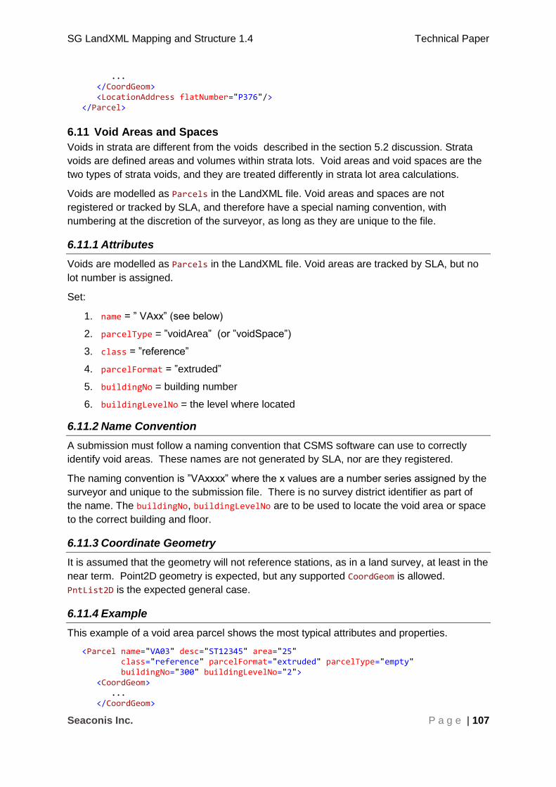
SG LandXML Mapping and Structure 1.4 Technical Paper
Seaconis Inc. P a g e | 107
... </CoordGeom> <LocationAddress flatNumber="P376"/> </Parcel>
6.11 Void Areas and Spaces
Voids in strata are different from the voids described in the section 5.2 discussion. Strata
voids are defined areas and volumes within strata lots. Void areas and void spaces are the
two types of strata voids, and they are treated differently in strata lot area calculations.
Voids are modelled as Parcels in the LandXML file. Void areas and spaces are not
registered or tracked by SLA, and therefore have a special naming convention, with
numbering at the discretion of the surveyor, as long as they are unique to the file.
6.11.1 Attributes
Voids are modelled as Parcels in the LandXML file. Void areas are tracked by SLA, but no
lot number is assigned.
Set:
1. name = ” VAxx” (see below)
2. parcelType = ”voidArea” (or ”voidSpace”)
3. class = ”reference”
4. parcelFormat = ”extruded”
5. buildingNo = building number
6. buildingLevelNo = the level where located
6.11.2 Name Convention
A submission must follow a naming convention that CSMS software can use to correctly
identify void areas. These names are not generated by SLA, nor are they registered.
The naming convention is ”VAxxxx” where the x values are a number series assigned by the
surveyor and unique to the submission file. There is no survey district identifier as part of
the name. The buildingNo, buildingLevelNo are to be used to locate the void area or space
to the correct building and floor.
6.11.3 Coordinate Geometry
It is assumed that the geometry will not reference stations, as in a land survey, at least in the
near term. Point2D geometry is expected, but any supported CoordGeom is allowed.
PntList2D is the expected general case.
6.11.4 Example
This example of a void area parcel shows the most typical attributes and properties.
<Parcel name="VA03" desc="ST12345" area="25" class="reference" parcelFormat="extruded" parcelType="empty" buildingNo="300" buildingLevelNo="2"> <CoordGeom> ... </CoordGeom>

SG LandXML Mapping and Structure 1.4 Technical Paper
Seaconis Inc. P a g e | 108
</Parcel>
7 Enumerations
The following appendix outlines all the LandXML type definitions used by the ePlan Protocol
in SG implementation. This includes the enumerated types.
7.1 Primitive Data Types
The following are primitive data type definitions. They are defined by the XML standard (see http://www.w3.org/TR/xmlschema-0/#CreatDt).
Type Description
anySimpleType Highest level of simple type. Can store any simple type.
anyURI Uniform Resource Identifier
boolean True of False
date ISO8601 date format (e.g. YYYY-MM-DD)
double A double precision floating point number
IDREF A reference to the ID of another element
int An integer
positiveInteger A positive integer value
string An extended sequence of characters
time ISO8601 time format (e.g. hh:mm:ss)
7.2 LandXML Enumerated Types
The following types are defined in LandXML with an enumerated list of valid values. This list contains only the LandXML types used by SG. Items in the enumeration not used by SG are indicated with “(NA)”. This is not an alteration of the enumeration, just showing the functional subset in the CSMS system. See LandXML1.2 schema for full list http://www.landxml.org/schema/LandXML-1.2/LandXML-1.2.xsd
The attributes are listed under the element to which they belong and are listed in the order in which the elements appear in this document.
Attribute Type Description Enumerations
Metric
directionUnit angularType Angular values
expressed in "decimal
dd.mm.ss" units have the
numeric format e.g.
Set to "decimal
dd.mm.ss"

SG LandXML Mapping and Structure 1.4 Technical Paper
Seaconis Inc. P a g e | 109
Attribute Type Description Enumerations
"45.3025" representing
45 degrees 30 minutes
and 25 seconds. Both the
minutes and seconds
must be two characters
with a numeric range
between 00 and 60
areaUnit metArea Valid metric units of
measure for area.
Set to "squareMeter"
linearUnit metLinear Valid metric units of
measure for length
Set to "meter"
pressureUnit metPressure Valid metric units of
measure for pressure
Set to "milliBars"
temperatureUnit metTemperature Valid metric units of
measure for temperature.
Set to "celsius"
volumeUnit metVolume Valid metric units of
measure for area
volume.
Set to "cubicMeter"
Curve
rot clockwise The direction of the
curve either clockwise
(cc) or counter
clockwise (ccw)
cw ccw
ReducedObservation
purpose purposeType enumeration of purpose
in survey
Note: use “normal” for
SG OBS, observation or
demarcation. Values
not used in SG are
labelled Not Applicable
(NA).
normal check
backsight foresight traverse
sideshot resection (NA) levelLoop (NA) digitalLevel (NA) remoteElevation(NA) recipricalObs (NA) topo (NA) cutSheets (NA)

SG LandXML Mapping and Structure 1.4 Technical Paper
Seaconis Inc. P a g e | 110
Attribute Type Description Enumerations
asBuilt (NA)
CgPoint
pntSurv survPntType The function the point
serves in the survey.
traverse reference administrative control boundary monument (NA) sideshot (NA) natural boundary (NA)
7.3 ICSM Jurisdiction Based Enumerated Types
The following types are defined as types in LandXML for the purpose of being extended with
jurisdictionally defined enumeration lists. Source files are available from ICSM. Types not
used by SG have been removed.
Type Description
adminDateTypeType This is the name of the admin date type for the Survey
annotationType An Annotation will be a specific type within a jurisdiction.
equipmentType This gives a list of equipment used for the observation this list of equipment is used to estimate the accuracy of the observation.
jurisdictionType This is the name of the jurisdiction in which the Survey lies (i.e. which state)
monumentState This is a list of states for a monument each jurisdiction may have a list defined by regulation.
monumentType This is a list of allowable monument types that can be used or identified for a survey, i.e. peg, spike, pillar etc. Local custom will define this list.
observationType This is a list of defined observation types, different jurisdictions may have a list defined by regulation can be defined by the jurisdiction.
parcelClass This is a list of parcel classes which may be jurisdictionally specific defined by regulation and legislation.
parcelFormat Parcel Format describes how the parcel is described , i.e. Standard (2D), Volumetric (3D)
purpSurvType This is a jurisdictionally based list of purposes of Survey and can be jurisdictionally specific for example Subdivision, Amalgamation (Consolidation) etc
survPntType To define the role of the point in the survey.

SG LandXML Mapping and Structure 1.4 Technical Paper
Seaconis Inc. P a g e | 111
7.4 SG Enumerated Types
The following types are defined as types in LandXML for the purpose of being extended with jurisdictionally defined enumeration lists. The attributes are listed under the element to which they belong and are listed in the order in which the elements appear in this document.
Coordinate System
Attribute Type Description Enumerations Definition
datum surveyDatumType Datum of the
survey
CASSINI
SVY21
0 in CGS
1 in CGS
horizontalDatum horizDatumType Horizontal
Datum
SVY21
verticalDatum vertDatumType Vertical datum
for Singapore
SHD
CgPoint
Attribute Type Description Enumerations Definition
desc approvalStateType The SLA class related to official status of the point.
allocation
activation
RT
final
dead
allocation
activation
Registration of Title
final
dead – historic.
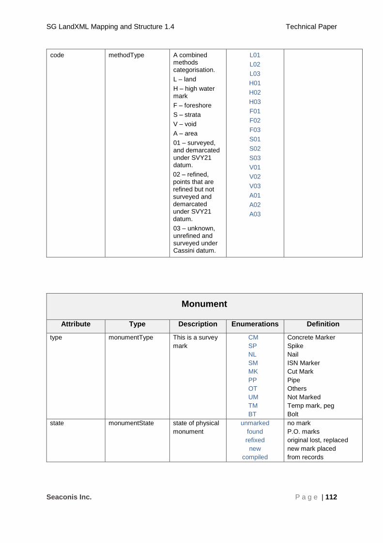
SG LandXML Mapping and Structure 1.4 Technical Paper
Seaconis Inc. P a g e | 112
code methodType A combined methods categorisation.
L – land
H – high water mark
F – foreshore
S – strata
V – void
A – area
01 – surveyed, and demarcated under SVY21 datum.
02 – refined, points that are refined but not surveyed and demarcated under SVY21 datum.
03 – unknown, unrefined and surveyed under Cassini datum.
L01
L02
L03
H01
H02
H03
F01
F02
F03
S01
S02
S03
V01
V02
V03
A01
A02
A03
Monument
Attribute Type Description Enumerations Definition
type monumentType This is a survey
mark
CM
SP
NL
SM
MK
PP
OT
UM
TM
BT
Concrete Marker
Spike
Nail
ISN Marker
Cut Mark
Pipe
Others
Not Marked
Temp mark, peg
Bolt
state monumentState state of physical
monument
unmarked
found
refixed
new
compiled
no mark
P.O. marks
original lost, replaced
new mark placed
from records

SG LandXML Mapping and Structure 1.4 Technical Paper
Seaconis Inc. P a g e | 113
Parcel
Attribute Type Description Enumerations Definition
parcelFormat parcelFormat format of
geometry
description
standard
surface
multisurface
extruded
volume
2D land or 2D strata
surface in 3D
patches in 3D
2D with lower and upper
elevations
3D Volume
parcelType parcelTypeType parcel type land
airspace
subterranean
empty
strata
accessory
stateReserve
foreshore
reclaimed
strataProvisional
surveyDistrict
building
level
common
typicalStorey
virtual
voidSpace
voidArea
standard land lot
above ground 3D
below ground 3D
void
within building
related to strata
restriction
abutting coast
land reclaimed from sea
or other water bodies
proposed strata lot
survey district
a building
a building level
common use areas
typical storey
virtual parcel referenced
by a typical storey
strata void space
strata void area
class parcelClass state or role in
the survey
parent
interim
final
reference
provisional
other
parent of final lots
temporary lot
submitted new lot
lot not in lineage or
physical parent, but
necessary for analysis
Approved provisional lot
to be used for analysis.
Not a lot
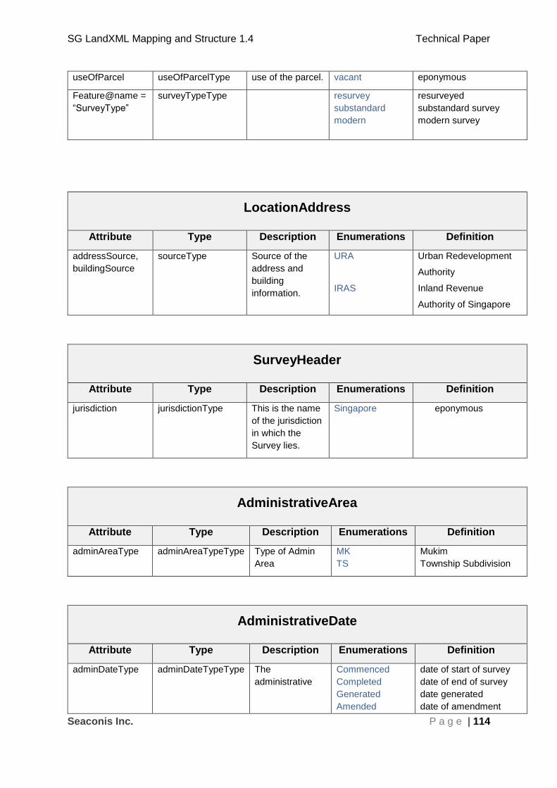
SG LandXML Mapping and Structure 1.4 Technical Paper
Seaconis Inc. P a g e | 114
useOfParcel useOfParcelType use of the parcel. vacant eponymous
Feature@name =
“SurveyType”
surveyTypeType resurvey
substandard
modern
resurveyed
substandard survey
modern survey
LocationAddress
Attribute Type Description Enumerations Definition
addressSource,
buildingSource
sourceType Source of the
address and
building
information.
URA
IRAS
Urban Redevelopment
Authority
Inland Revenue
Authority of Singapore
SurveyHeader
Attribute Type Description Enumerations Definition
jurisdiction jurisdictionType This is the name
of the jurisdiction
in which the
Survey lies.
Singapore eponymous
AdministrativeArea
Attribute Type Description Enumerations Definition
adminAreaType adminAreaTypeType Type of Admin
Area
MK
TS
Mukim
Township Subdivision
AdministrativeDate
Attribute Type Description Enumerations Definition
adminDateType adminDateTypeType The
administrative
Commenced
Completed
Generated
Amended
date of start of survey
date of end of survey
date generated
date of amendment
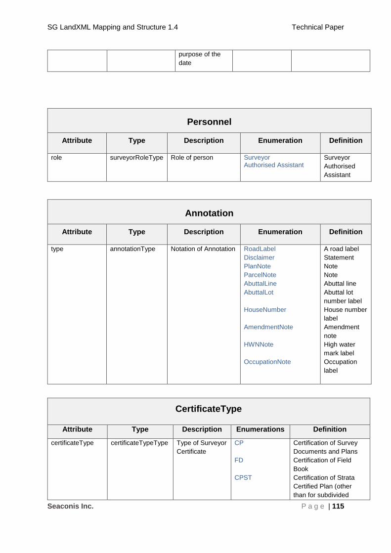
SG LandXML Mapping and Structure 1.4 Technical Paper
Seaconis Inc. P a g e | 115
purpose of the
date
Personnel
Attribute Type Description Enumeration Definition
role surveyorRoleType Role of person Surveyor Authorised Assistant
Surveyor
Authorised
Assistant
Annotation
Attribute Type Description Enumeration Definition
type annotationType Notation of Annotation RoadLabel
Disclaimer
PlanNote
ParcelNote
AbuttalLine
AbuttalLot
HouseNumber
AmendmentNote
HWNNote
OccupationNote
A road label
Statement
Note
Note
Abuttal line
Abuttal lot
number label
House number
label
Amendment
note
High water
mark label
Occupation
label
CertificateType
Attribute Type Description Enumerations Definition
certificateType certificateTypeType Type of Surveyor
Certificate
CP
FD
CPST
Certification of Survey
Documents and Plans
Certification of Field
Book
Certification of Strata
Certified Plan (other
than for subdivided

SG LandXML Mapping and Structure 1.4 Technical Paper
Seaconis Inc. P a g e | 116
STP
CS
building)
Certification of Strata
Title Plan
Certification of Chief
Surveyor
DocFileRef
Attribute Type Description Enumerations Definition
fileType fileTypeType This is for stating
the type of file
attached as
supporting
document.
ReferencePlan Reference plan
PurposeOfSurvey
Attribute Type Description Enumeration Definition
name purpSurvType See Appendix B See Appendix B See Appendix B
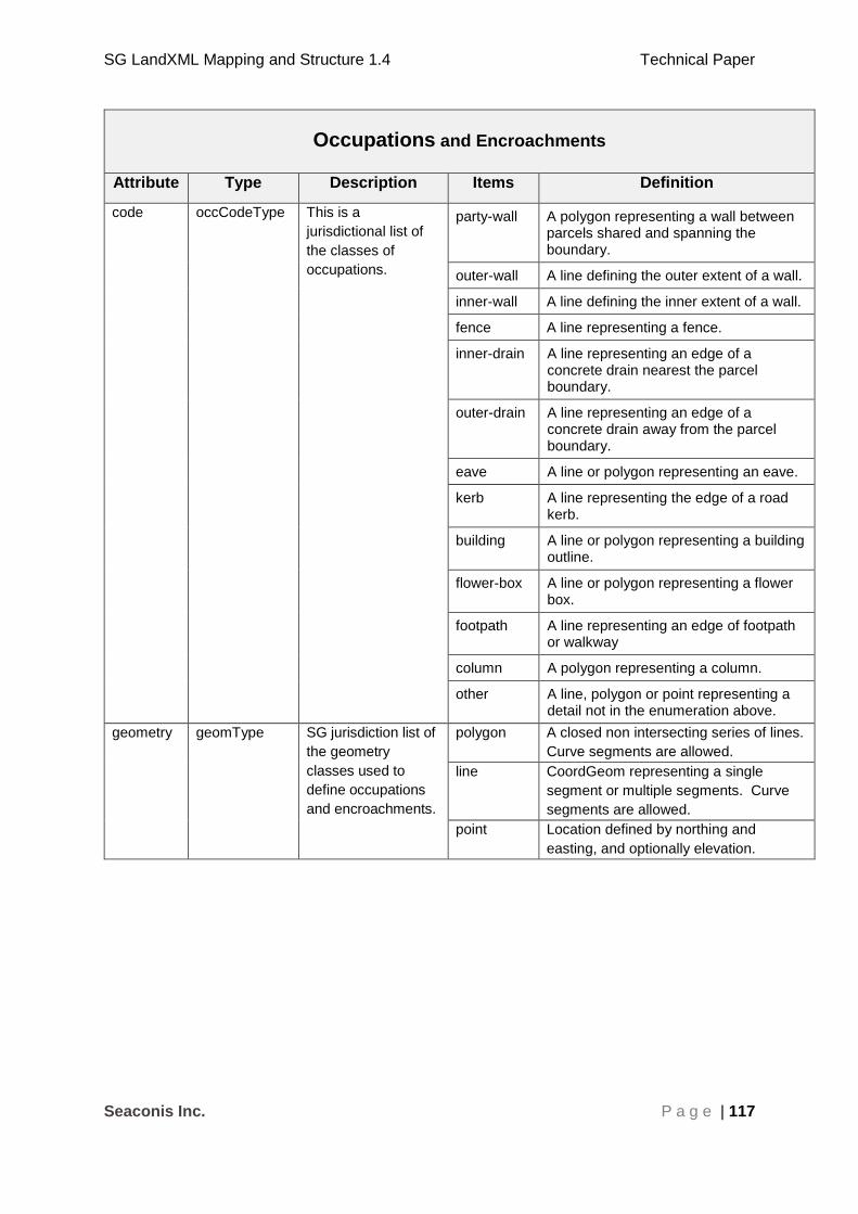
SG LandXML Mapping and Structure 1.4 Technical Paper
Seaconis Inc. P a g e | 117
Occupations and Encroachments
Attribute Type Description Items Definition
code occCodeType This is a
jurisdictional list of
the classes of
occupations.
party-wall A polygon representing a wall between parcels shared and spanning the boundary.
outer-wall A line defining the outer extent of a wall.
inner-wall A line defining the inner extent of a wall.
fence A line representing a fence.
inner-drain A line representing an edge of a concrete drain nearest the parcel boundary.
outer-drain A line representing an edge of a concrete drain away from the parcel boundary.
eave A line or polygon representing an eave.
kerb A line representing the edge of a road kerb.
building A line or polygon representing a building outline.
flower-box A line or polygon representing a flower box.
footpath A line representing an edge of footpath or walkway
column A polygon representing a column.
other A line, polygon or point representing a detail not in the enumeration above.
geometry geomType SG jurisdiction list of
the geometry
classes used to
define occupations
and encroachments.
polygon A closed non intersecting series of lines.
Curve segments are allowed.
line CoordGeom representing a single
segment or multiple segments. Curve
segments are allowed.
point Location defined by northing and
easting, and optionally elevation.

SG LandXML Mapping and Structure 1.4 Technical Paper
Seaconis Inc. P a g e | 118
8 Appendix A – Non-CSMS Ancillary Files
In the pre-CSMS system, there are many data files that are part of a normal submission.
Most of these are small files, which contain only a few records each of specific administrative
information. There are also Sketches (SK), Field Details (FD) and plans, all of which are
submitted as scanned images. The long term goal is to move the information contained in
these various files into the SG LandXML to facilitate a better automation of the cadastral
transaction processes. Some of this data will be readily amendable to inclusion in the XML,
other bits, not so easily.
In particular, the Sketches, Field Details and Plans record information in drawings which can
be difficult to transition to digital data records. Most jurisdictions have taken several years in
the move from paper (and scanned images are just paper in this context) to all digital
cadastre. In many cadastres, document images are still a part of the submission, even when
it duplicates data submitted as digital records.
It is our plan to merge these disparate data files into the SG LandXML as deemed
appropriate and tractable. This will follow the first LandXML modelling for the survey data.
In addition to the modelling of the data in LandXML, the effects on existing systems, not
planned to be a part of the new CSMS will need to be considered. Perhaps the
administrative data can be channeled through the new portal being constructed, to the
necessary systems. The notion of consolidating Sketches, Field Details and Plans requires
a more involved analysis. This would present difficulties in that it would change the
surveying practices as well as make further demands on the software used for submission of
jobs. It would also alter the legal definition of documents.
Several submission files are digital scans of legal documents, so it is likely that some digital
images will be a part of the submission into the future. These could, however be referenced
by name in the SG LandXML to create a fully automated submission. Such an approach
that considers a packet submission approach has been used elsewhere.
Therefore, no expectation of the complete digital data submission in SG LandXML is
presently tenable. Additional analysis and planning will be forthcoming, and this document
maintains its focus on the survey data in existing data files. We should consider the SG
LandXML to be developed in three phases:
1. The currently planned inclusion of survey data from JOB/SVY files, and the extension to cover 3D survey data for airspace, subterranean and strata plans.
2. The assimilation of administrative and sundry data in other submission files.
3. The transformation of image files containing sketches, drawings and legal communications. Some of which will likely remain in image format.
8.1 Permits Permission and Addresses
The project must coordinate requests and communications with other government agencies,
for permits permissions and other planning activities.
These files include:
SG LandXML Mapping and Structure 1.4 Technical Paper
Seaconis Inc. P a g e | 119
1. IRAS_House No.pdf – House addresses and diagram from the Inland Revenue Authority of Singapore. Addresses are covered in SG LandXML, and present in SVY.
2. Grant of Written Permission.pdf – planning approval.
In some cases, these documents contain information found in the SG LandXML. However,
there may be a need to have the original documents presented along with the job.
8.2 Files Produced During Submission Processing
Several files, usually Microsoft Excel files, are generated by SLA after the surveyor has
completed forms in the submission process. The current agreed position is that any such
information should be stored in SLA databases, and not included in the submitted SG
LandXML through any editing process. That is, the SG LandXML file submitted by the
surveyor should be ‘read only’.
These files include:
1. CALCULATION_OF_SURVEY_FEES.XLS - This is entitled Calculation of Survey Fees Payable to Chief Surveyor. It contains fees by lot.
2. COMPARISON_OF_AREAS.XLS – a spread sheet comparing parent and child areas
3. ES_SUBMISSION.XML – a record of the submission including reference to all files.
4. PROJECT-PROFILE.XML Project and Member profiles for the project/job.
5. ES(job number).log – record of submission success or failure.
6. SUBMISSION.XML - similar to ES_SUBMISSION.XML , but different element names. References generated by a different system.
7. AUTHORISATION_FOR_DEDUCTION_OF_SURVEY_FEES.doc – A form that authorizes SLA to deduct the survey fees from the surveyor’s GIRO account.
8. SURVEY_REPORT.DOC - A summary report for the survey job done.
9. CERTIFICATE_IN_RELATION_TO_ENCROACHMENT.DOC - A document form to declare if any encroachment found has been resolved.
These files contain information found in SG LandXML and can be used for calculation of
survey fees and generation of summary report. A declaration form can be submitted and
stored directly to database through the RS portal. Some of these file that are system
generated would not be needed in the new system.
8.3 Surveyor Prepared Files
Many submission files are a direct result to the survey efforts in the field and office. These
include the survey data in various forms.
These files are”
1. JOB – contains field and equipment data already covered by SG LandXML sections.
2. SVY – contains adjusted survey data already covered by SG LandXML sections.
3. CP*.dwf – certified plan drawings in Autodesk Design Web Format.
4. SK*.tiff – sketches (drawings) scanned into raster image files (Tagged Information File Format).
5. PDF – contains scanned sketches (drawings) and physical documents.

SG LandXML Mapping and Structure 1.4 Technical Paper
Seaconis Inc. P a g e | 120
8.4 Sketches
There are different sketches required for different type of submissions.
These sketches are required for CP:
1. Traverse Sketch
2. Demarcation Sketch
3. Details Sketch
4. Party-wall Sketch
These sketches are required for CPST:
1. Site Plan
2. Elevation Sketch
3. Storey Plan
The above listed sketches will no longer be needed when the information is stored in the SG
LandXML.
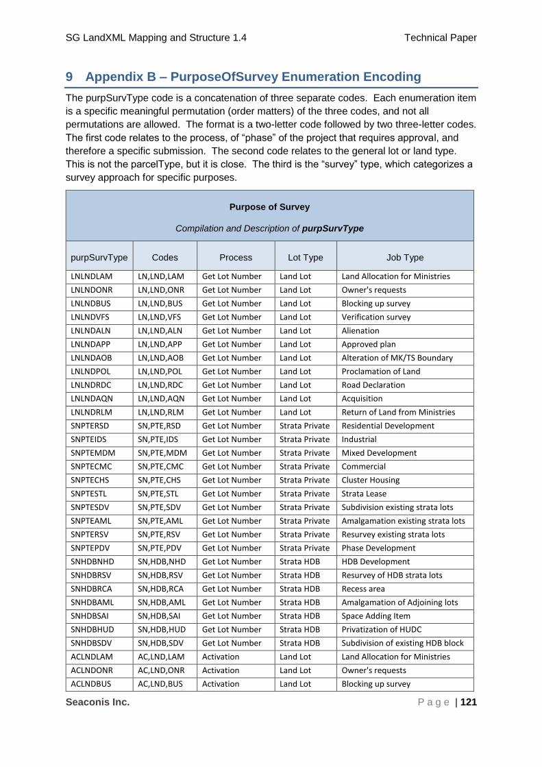
SG LandXML Mapping and Structure 1.4 Technical Paper
Seaconis Inc. P a g e | 121
9 Appendix B – PurposeOfSurvey Enumeration Encoding
The purpSurvType code is a concatenation of three separate codes. Each enumeration item
is a specific meaningful permutation (order matters) of the three codes, and not all
permutations are allowed. The format is a two-letter code followed by two three-letter codes.
The first code relates to the process, of “phase” of the project that requires approval, and
therefore a specific submission. The second code relates to the general lot or land type.
This is not the parcelType, but it is close. The third is the “survey” type, which categorizes a
survey approach for specific purposes.
Purpose of Survey
Compilation and Description of purpSurvType
purpSurvType Codes Process Lot Type Job Type
LNLNDLAM LN,LND,LAM Get Lot Number Land Lot Land Allocation for Ministries
LNLNDONR LN,LND,ONR Get Lot Number Land Lot Owner's requests
LNLNDBUS LN,LND,BUS Get Lot Number Land Lot Blocking up survey
LNLNDVFS LN,LND,VFS Get Lot Number Land Lot Verification survey
LNLNDALN LN,LND,ALN Get Lot Number Land Lot Alienation
LNLNDAPP LN,LND,APP Get Lot Number Land Lot Approved plan
LNLNDAOB LN,LND,AOB Get Lot Number Land Lot Alteration of MK/TS Boundary
LNLNDPOL LN,LND,POL Get Lot Number Land Lot Proclamation of Land
LNLNDRDC LN,LND,RDC Get Lot Number Land Lot Road Declaration
LNLNDAQN LN,LND,AQN Get Lot Number Land Lot Acquisition
LNLNDRLM LN,LND,RLM Get Lot Number Land Lot Return of Land from Ministries
SNPTERSD SN,PTE,RSD Get Lot Number Strata Private Residential Development
SNPTEIDS SN,PTE,IDS Get Lot Number Strata Private Industrial
SNPTEMDM SN,PTE,MDM Get Lot Number Strata Private Mixed Development
SNPTECMC SN,PTE,CMC Get Lot Number Strata Private Commercial
SNPTECHS SN,PTE,CHS Get Lot Number Strata Private Cluster Housing
SNPTESTL SN,PTE,STL Get Lot Number Strata Private Strata Lease
SNPTESDV SN,PTE,SDV Get Lot Number Strata Private Subdivision existing strata lots
SNPTEAML SN,PTE,AML Get Lot Number Strata Private Amalgamation existing strata lots
SNPTERSV SN,PTE,RSV Get Lot Number Strata Private Resurvey existing strata lots
SNPTEPDV SN,PTE,PDV Get Lot Number Strata Private Phase Development
SNHDBNHD SN,HDB,NHD Get Lot Number Strata HDB HDB Development
SNHDBRSV SN,HDB,RSV Get Lot Number Strata HDB Resurvey of HDB strata lots
SNHDBRCA SN,HDB,RCA Get Lot Number Strata HDB Recess area
SNHDBAML SN,HDB,AML Get Lot Number Strata HDB Amalgamation of Adjoining lots
SNHDBSAI SN,HDB,SAI Get Lot Number Strata HDB Space Adding Item
SNHDBHUD SN,HDB,HUD Get Lot Number Strata HDB Privatization of HUDC
SNHDBSDV SN,HDB,SDV Get Lot Number Strata HDB Subdivision of existing HDB block
ACLNDLAM AC,LND,LAM Activation Land Lot Land Allocation for Ministries
ACLNDONR AC,LND,ONR Activation Land Lot Owner's requests
ACLNDBUS AC,LND,BUS Activation Land Lot Blocking up survey
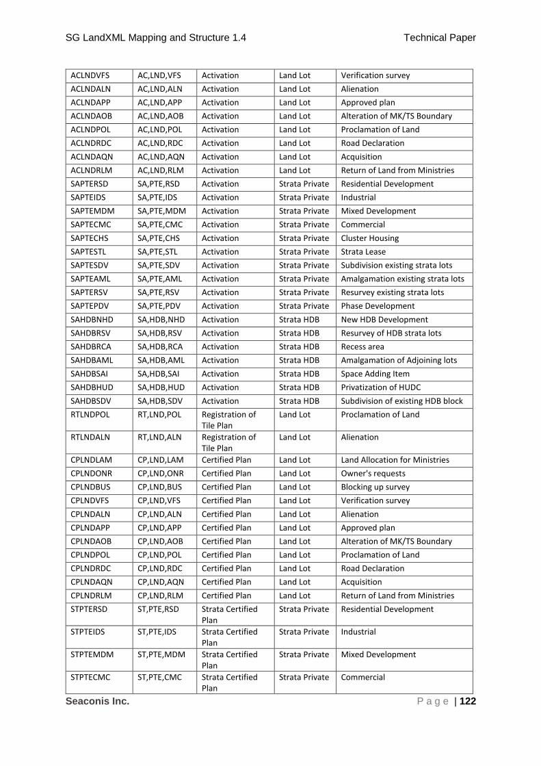
SG LandXML Mapping and Structure 1.4 Technical Paper
Seaconis Inc. P a g e | 122
ACLNDVFS AC,LND,VFS Activation Land Lot Verification survey
ACLNDALN AC,LND,ALN Activation Land Lot Alienation
ACLNDAPP AC,LND,APP Activation Land Lot Approved plan
ACLNDAOB AC,LND,AOB Activation Land Lot Alteration of MK/TS Boundary
ACLNDPOL AC,LND,POL Activation Land Lot Proclamation of Land
ACLNDRDC AC,LND,RDC Activation Land Lot Road Declaration
ACLNDAQN AC,LND,AQN Activation Land Lot Acquisition
ACLNDRLM AC,LND,RLM Activation Land Lot Return of Land from Ministries
SAPTERSD SA,PTE,RSD Activation Strata Private Residential Development
SAPTEIDS SA,PTE,IDS Activation Strata Private Industrial
SAPTEMDM SA,PTE,MDM Activation Strata Private Mixed Development
SAPTECMC SA,PTE,CMC Activation Strata Private Commercial
SAPTECHS SA,PTE,CHS Activation Strata Private Cluster Housing
SAPTESTL SA,PTE,STL Activation Strata Private Strata Lease
SAPTESDV SA,PTE,SDV Activation Strata Private Subdivision existing strata lots
SAPTEAML SA,PTE,AML Activation Strata Private Amalgamation existing strata lots
SAPTERSV SA,PTE,RSV Activation Strata Private Resurvey existing strata lots
SAPTEPDV SA,PTE,PDV Activation Strata Private Phase Development
SAHDBNHD SA,HDB,NHD Activation Strata HDB New HDB Development
SAHDBRSV SA,HDB,RSV Activation Strata HDB Resurvey of HDB strata lots
SAHDBRCA SA,HDB,RCA Activation Strata HDB Recess area
SAHDBAML SA,HDB,AML Activation Strata HDB Amalgamation of Adjoining lots
SAHDBSAI SA,HDB,SAI Activation Strata HDB Space Adding Item
SAHDBHUD SA,HDB,HUD Activation Strata HDB Privatization of HUDC
SAHDBSDV SA,HDB,SDV Activation Strata HDB Subdivision of existing HDB block
RTLNDPOL RT,LND,POL Registration of Tile Plan
Land Lot Proclamation of Land
RTLNDALN RT,LND,ALN Registration of Tile Plan
Land Lot Alienation
CPLNDLAM CP,LND,LAM Certified Plan Land Lot Land Allocation for Ministries
CPLNDONR CP,LND,ONR Certified Plan Land Lot Owner's requests
CPLNDBUS CP,LND,BUS Certified Plan Land Lot Blocking up survey
CPLNDVFS CP,LND,VFS Certified Plan Land Lot Verification survey
CPLNDALN CP,LND,ALN Certified Plan Land Lot Alienation
CPLNDAPP CP,LND,APP Certified Plan Land Lot Approved plan
CPLNDAOB CP,LND,AOB Certified Plan Land Lot Alteration of MK/TS Boundary
CPLNDPOL CP,LND,POL Certified Plan Land Lot Proclamation of Land
CPLNDRDC CP,LND,RDC Certified Plan Land Lot Road Declaration
CPLNDAQN CP,LND,AQN Certified Plan Land Lot Acquisition
CPLNDRLM CP,LND,RLM Certified Plan Land Lot Return of Land from Ministries
STPTERSD ST,PTE,RSD Strata Certified Plan
Strata Private Residential Development
STPTEIDS ST,PTE,IDS Strata Certified Plan
Strata Private Industrial
STPTEMDM ST,PTE,MDM Strata Certified Plan
Strata Private Mixed Development
STPTECMC ST,PTE,CMC Strata Certified Plan
Strata Private Commercial
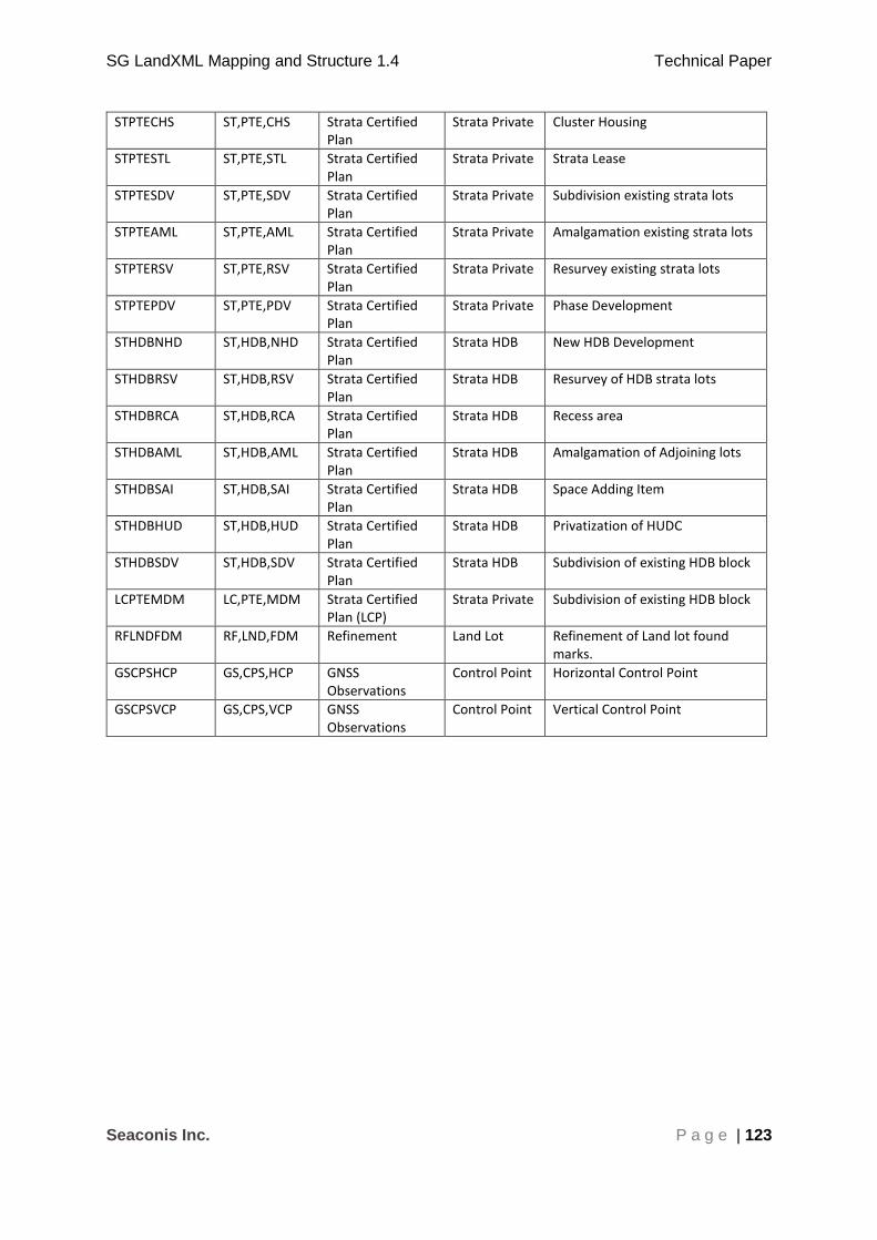
SG LandXML Mapping and Structure 1.4 Technical Paper
Seaconis Inc. P a g e | 123
STPTECHS ST,PTE,CHS Strata Certified Plan
Strata Private Cluster Housing
STPTESTL ST,PTE,STL Strata Certified Plan
Strata Private Strata Lease
STPTESDV ST,PTE,SDV Strata Certified Plan
Strata Private Subdivision existing strata lots
STPTEAML ST,PTE,AML Strata Certified Plan
Strata Private Amalgamation existing strata lots
STPTERSV ST,PTE,RSV Strata Certified Plan
Strata Private Resurvey existing strata lots
STPTEPDV ST,PTE,PDV Strata Certified Plan
Strata Private Phase Development
STHDBNHD ST,HDB,NHD Strata Certified Plan
Strata HDB New HDB Development
STHDBRSV ST,HDB,RSV Strata Certified Plan
Strata HDB Resurvey of HDB strata lots
STHDBRCA ST,HDB,RCA Strata Certified Plan
Strata HDB Recess area
STHDBAML ST,HDB,AML Strata Certified Plan
Strata HDB Amalgamation of Adjoining lots
STHDBSAI ST,HDB,SAI Strata Certified Plan
Strata HDB Space Adding Item
STHDBHUD ST,HDB,HUD Strata Certified Plan
Strata HDB Privatization of HUDC
STHDBSDV ST,HDB,SDV Strata Certified Plan
Strata HDB Subdivision of existing HDB block
LCPTEMDM LC,PTE,MDM Strata Certified Plan (LCP)
Strata Private Subdivision of existing HDB block
RFLNDFDM RF,LND,FDM Refinement Land Lot Refinement of Land lot found marks.
GSCPSHCP GS,CPS,HCP GNSS Observations
Control Point Horizontal Control Point
GSCPSVCP GS,CPS,VCP GNSS Observations
Control Point Vertical Control Point

SG LandXML Mapping and Structure 1.4 Technical Paper
Seaconis Inc. P a g e | 124
Contributing Aspect Encoding
purpSurvType
Code Description
LN Get Lot Number (Land)
SN Get Lot Number (Strata)
AC Activation of Caveat Lot Numbers (Land)
SA Activation of Caveat Lot Numbers (Strata)
RT Registrar of Title Plan
CP Certified Plan
ST Strata Certified Plan
LC Strata Certified Plan (LCP)
RF Refinement
LND Land
PTE Private Strata
HDB HDB Strata
LAM Land Allocation for Ministries
ONR Owner's requests
BUS Blocking up survey
VFS Verification survey
ALN Alienation
APP Approved plan
AOB Alteration of MK/TS Boundary
POL Proclamation of Land
RDC Road Declaration
AQN Acquisition
RLM Return of Land from Ministries
NHD New HDB Development
RCA Recess area
SAI Space Adding Item
HUD Privatization of HUDC
RSD Residential Development
IDS Industrial
MDM Mixed Development
CMC Commercial
CHS Cluster Housing
STL Strata Lease
SDV Subdivision existing strata lots
AML Amalgamation existing strata lots
RSV Resurvey existing strata lots
PDV Phase Development
CPS Control Point Submission
HCP Horizontal Control Point
VCP Vertical Control Point
FDM Found Marks
SG LandXML Mapping and Structure 1.4 Technical Paper
Seaconis Inc. P a g e | 125
Works Cited
Singapore Land Authority. (2015). Chief Surveyor Directive on Cadastral Survey Practices. (version 4.0).
Singapore Land Authority. (2011). Guidelines and Specifications for GPS Surveys of ISN Markers. (version 2.4).
ICSM. (2011). ePlan Protocol – LandXML Mapping (v2.1.2). eplan-working-group/http://icsm-eplan.govspace.gov.au/eplan-working-group/eplan-protocol/
ICSM. (2010). ePlan Protocol – LandXML Structural Requirements (v1.0). http://icsm-eplan.govspace.gov.au/eplan-working-group/eplan-protocol/
W3C. (2008). Extensible Markup Language (XML) (v1.0, Fifth Edition) http://www.w3.org/TR/xml/


