Hitachi Industrial Equipment Systems Co.,Ltd.
SJ200-****EF Type
1
Hitachi's new technology inverter family is suitable for a wide High performance is now within your grasp.
Compact, high-torque, full-featured drive, Compact, high-torque, full-featured drive,
1
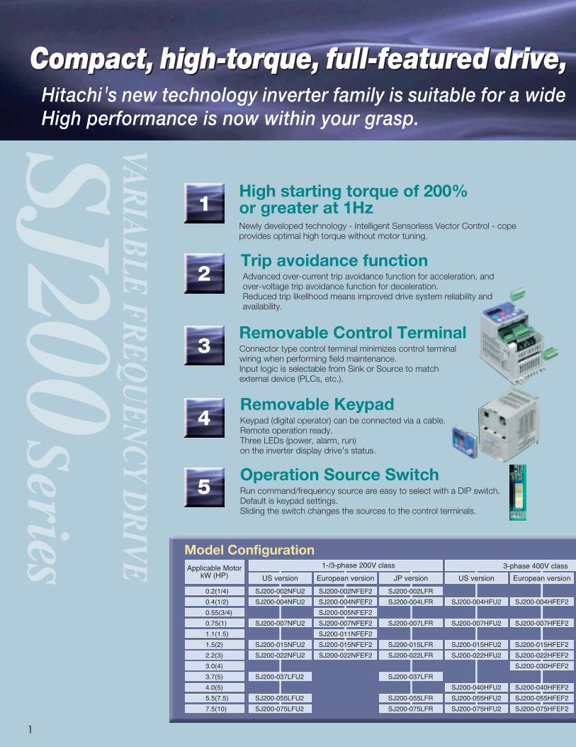
Model Configuration
High starting torque of 200% or greater at 1HzNewly developed technology - Intelligent Sensorless Vector Control - cope provides optimal high torque without motor tuning.
Trip avoidance functionAdvanced over-current trip avoidance function for acceleration, andover-voltage trip avoidance function for deceleration.Reduced trip likelihood means improved drive system reliability andavailability.
Removable Control TerminalConnector type control terminal minimizes control terminalwiring when performing field maintenance. Input logic is selectable from Sink or Source to matchexternal device (PLCs, etc.).
Removable KeypadKeypad (digital operator) can be connected via a cable. Remote operation ready.Three LEDs (power, alarm, run) on the inverter display drive's status.
Operation Source SwitchRun command/frequency source are easy to select with a DIP switch.Default is keypad settings. Sliding the switch changes the sources to the control terminals.
1
2
3
4
5
SJ200Series
VARIABLE FREQU
ENCY D
RIVE
Applicable MotorkW (HP)
0.2(1/4)
0.4(1/2)
0.55(3/4)
0.75(1)
1.1(1.5)
1.5(2)
2.2(3)
3.0(4)
3.7(5)
4.0(5)
5.5(7.5)
7.5(10)
1-/3-phase 200V class
US version
SJ200-002NFU2
SJ200-004NFU2
SJ200-007NFU2
SJ200-015NFU2
SJ200-022NFU2
SJ200-037LFU2
SJ200-055LFU2
SJ200-075LFU2
European version JP version
SJ200-002NFEF2
SJ200-004NFEF2
SJ200-005NFEF2
SJ200-007NFEF2
SJ200-011NFEF2
SJ200-015NFEF2
SJ200-022NFEF2
SJ200-002LFR
SJ200-004LFR
SJ200-007LFR
SJ200-015LFR
SJ200-022LFR
SJ200-037LFR
SJ200-055LFR
SJ200-075LFR
3-phase 400V class
US version
SJ200-004HFU2
SJ200-007HFU2
SJ200-015HFU2
SJ200-022HFU2
SJ200-040HFU2
SJ200-055HFU2
SJ200-075HFU2
European version
SJ200-004HFEF2
SJ200-007HFEF2
SJ200-015HFEF2
SJ200-022HFEF2
SJ200-030HFEF2
SJ200-040HFEF2
SJ200-055HFEF2
SJ200-075HFEF2

2
range of drive applications.
yet easy-to-use.yet easy-to-use.
2
Model Name Indication
Improved PID controlReverse PID function changes the sign of the deviation value which is the differencebetween target and feedback values.Upper and lower limits from a target value can be imposed on the inverter output frequency.
Analog setpointcalculate functionsAn offset frequency can be added to or subtracted from the output frequency when ADD terminal is ON.For example, if output frequency setting is 40Hz andoffset frequency is 5Hz, output frequency becomes45Hz (or 35Hz) when ADD terminal is ON.
Versatile Functions• Pure analog monitor output (8-bit, 0-10V DC)• External thermistor terminal (PTC)• Cooling-fan on/off• Side-by-side installation• Regenerative braking circuit• Instantaneous power failure recovery• Second motor setting• Over-voltage suppression at deceleration• 3-wire control• RS-485 Serial port with Modbus®-RTU• Analog input selection• Second acceleration/deceleration setting• Jogging• Auto-carrier frequency reduction• Unattended start protection (USP)• Analog input wire-break detection
Global Performance• Conformity to global standards.
CE, UL, c-UL and c-Tick approvals.
• Network Compatibility.The SJ200-2 can communicate with PROFIBUS®.CANopen with communication options.
〈CE〉 〈UL,c-UL〉 〈c-Tick〉
6
7
9
8
10
11
ISO 14001EC97J1095
ISO 9001JQA-1153
Hitachi variable frequencydrives (inverters) in thisbrochure are produced at thefactory registered under theISO 14001 standard forenvironmental managementsystem and the ISO 9001standard for inverter qualitymanagement system.
FeaturesStandard SpecificationsDimensionsOperation and ProgrammingOperation / Terminal FunctionsFunction ListProtective FunctionsConnecting DiagramWiring and AccessoriesFor Correct Operation
CONTENTS1-2
3456
7-9101112
13-14
Output Timingand Logic functionsOutput terminals can be assigned logical operatorsAND, OR and XOR with RUN, AL and so on. ON and OFF delay times are settable for each output terminal. Allows for more flexible system design.
Integrated EMC FilterReduces electromagnetic noise. (on European-Version units only)
SJ200-004 H F E F 2
Series Name
Applicable MotorCapacity002: 0.2kW(1/4HP)
|075: 7.5kW(10HP)
Power SourceN : 1 or 3 phase 200V classL : 3-phase 200V classH : 3-phase 400V class
F : With keypad
U : US versionE : European versionR : Japanese version
F : Integrated EMC filter
Version NumberJP version
SJ200-004HFR
SJ200-007HFR
SJ200-015HFR
SJ200-022HFR
SJ200-037HFR
SJ200-055HFR
SJ200-075HFR
SJ200-****EF2 Type
1-/3-phase 200V class
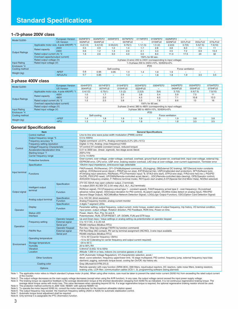
Standard Specifications
3
Item General SpecificationsLine-to-line sine wave pulse-width modulation (PWM) control0.5 to 400HzDigital command :±0.01%, Analog command±0.2% (25 ±10˚C)Digital: 0.1Hz, Analog: (max frequency)/1000V/f control,V/f variable (constant torque, reduced torque)0.01 to 3000 sec. (linear, sigmoid), two-stage accel./decel.200%/1Hz2.0 to 14.0kHzOver-current, over-voltage, under-voltage, overload, overheat, ground fault at power-on, overload limit, input over-voltage, external trip,EEPROM error, CPU error, USP error, braking resistor overload, LAD stop at over-voltage, over-current suppression, Termister error10kohm input impedance, sink/source logic selectable
FW(Forward), RV(Reverse), CF1-CF4(Multispeed command), JG(Jogging), DB(External DC braking), SET(Second motor constantssetting), 2CH(Second accel./decel.), FRS(Free-run stop), EXT(External trip), USP(Unattended start protection), SFT(Software lock),AT(Analog input selection), RS(Reset), PTC(Thermistor input) *8, STA(3-wire start), STP(3-wire stop), F/R(3-wire fwd./rev.), PID(PIDOn/Off), PIDC(PID reset), UP/DWN(Remote-controlled accel./decel.) , UDC(Remote-controlled data clearing), OPE(Operator control),ADD(ADD frequency enable), F-TM(force terminal mode), RDY(quick start enable),S-ST(Special-Set 2nd Motor Data), NO(Not selected)
27V DC 50mA max open collector output, 2 terminals1c output 250V AC/30V DC 2.5A relay (AL0, AL1, AL2 terminals)
RUN(run signal), FA1(Frequency arrival type 1 - constant speed), FA2(Frequency arrival type 2 - over-frequency), OL(overloadadvance notice signal), OD(Output deviation for PID control), AL(alarm signal), DC(Wire brake detect on analog input), FBV(PIDSecond Stage Output), NDC(ModBus Network Detection Signal), LOG(Logic Output Function), ODC(Option Card Detection Signal)
0 to 10V DC (8-bit resolution)Analog Frequency monitor, analog current monitor4-digits 7 segment LEDsParameter setting, output frequency, output current, motor torque, scaled value of output frequency, trip history, I/O terminal condition,input power, output voltage. Rotation direction, PID Feedback, RON time, Power-on time.Power, Alarm, Run, Prg, Hz and APotentiometer, RUN, STOP/RESET, UP, DOWN, FUN and STR keysUp and Down keys / Value settings or analog setting via potentiometer on operator keypad0 to 10 V DC, 4 to 20 mARS485 interface (Modbus RTU)Run key / Stop key (change FW/RV by function command)FW Run/Stop (NO contact), RV set by terminal assignment (NC/NO), 3-wire input availableRS485 interface (Modbus RTU)-10 to 40˚C(carrier frequency ≤5kHz)-10 to 50˚C(derating for carrier frequency and output current required)-20 to 65˚C20 to 90% RH5.9mm/s2 (0.6G) 10 to 55HzAltitude 1,000 m or less, indoors (no corrosive gasses or dust)AVR (Automatic Voltage Regulation), V/f characteristic selection, accel./decel. curve selection, frequency upper/lower limit, 16 stage multispeed, PID control, frequency jump, external frequency input biasstart/end, jogging, automatic torque boost, cooling fan On/Off, trip history etc.Gray (Munsell 8.5YR6.2/0.2)Remote operator with copy function (SRW-0EX), EMI filters, input/output reactors, DC reactors, radio noise filters, braking resistors,braking units, LCR filter, communication cables (ICS-1, 3), programming software (being planned)
Control
Input terminal
Output signal
Operator
Operation
Environment
Other functions
Coating color
Options
Control methodOutput frequency range *5Frequency accuracy *6Frequency setting resolutionVoltage/Frequency CharacteristicAcceleration/deceleration timeStarting torque *7Carrier frequency range
Protective functions
Specification
Functions
Intelligent outputterminal
Analog output terminal
Display
Status LEDInterface
Frequency setting
FW/RV Run
Operating temperature
Storage temperatureHumidityVibrationLocation
Operator keypadExternal signalSerial portOperator KeypadExternal signalSerial port
Specification
Function
SpecificationFunctionSpecification
Function
General Specifications
Note 1: The applicable motor refers to Hitachi standard 3-phase motor (4-pole). When using other motors, care must be taken to prevent the rated motor current (50/60 Hz) from exceeding the rated output currentof the inverter.
Note 2: The output voltage decreases as the main supply voltage decreases (except when using the AVR function). In any case, the output voltage cannot exceed the input power supply voltage.Note 3: The braking torque via capacitive feedback is the average deceleration torque at the shortest deceleration (stopping from 50/60 Hz as indicated). It is not continuous regenerative braking torque. The
average decel torque varies with motor loss. This value decreases when operating beyond 50 Hz. If a large regenerative torque is required, the optional regenerative braking resistor should be used.Note 4: The protection method conforms to JEM 1030. NEMA1 with optional NEMA1 kit.Note 5: To operate the motor beyond 50/60 Hz, consult the motor manufacturer for the maximum allowable rotation speed.Note 6: The output frequency may exceed the maximum frequency setting (A004 or A204) for automatic stabilization control.Note 7: Automatic torque boost adjustment shall be required.Note 8: Only terminal 5 is assignable the PTC (thermistor) function.
Model SJ200- 004HFEF2004HFU20.4(1/2)
1.01.21.5
007HFEF2007HFU2
0.75(1)1.72.02.5
015HFEF2015HFU2
1.5 (2)2.63.13.8
022HFEF2022HFU2
2.2(3)3.84.55.5
030HFEF2-
3(4)5.46.57.8
040HFEF2040HFU2
3.7(5)5.97.18.6
055HFEF2055HFU25.5(7.5)
7.510.813
075HFEF2075HFU27.5(10)
1113.316
150% for 60 sec.3-phase (3-wire) 380 to 480V (corresponding to input voltage)
3-phase 380 to 480V±10%, 50/60Hz±5%IP20
Self-cooling Force ventilation1.41.3
Output Ratings
Input RatingEnclosure *4Cooling method
Weight (kg)
Rated input voltage (V)
Applicable motor size, 4-pole kW(HP) *1
Rated capacity
Rated output current (A) *2Overload capacity(output current)Rated output voltage (V)
3-phase 400V class
400V480V
European VersionUS Version
-HFEF-HFU
1.81.7
1.91.8
1.91.8
1.9-
1.91.8
3.83.5
3.83.5
Model SJ200- 002NFEF2002NFU20.2(1/4)
0.50.61.6
004NFEF2004NFU20.4(1/2)
0.91.22.6
005NFEF2-
0.55(3/4)1.01.33.0
007NFEF2007NFU20.75(1)
1.42.04.0
011NFEF2-
1.1(1.5)1.72.15.0
015NFEF2015NFU2
1.5 (2)2.83.38.0
022NFEF2022NFU2
2.2(3)3.84.5
11.0
-037LFU2
3.7(5)6.07.217.5
-055LFU25.5(7.5)
7.59.924
-075LFU27.5(10)
1113.332
150% for 60 sec.3-phase (3-wire) 200 to 240V (corresponding to input voltage)
1-/3-phase 200 to 240V±10%, 50/60Hz±5%IP20
Self-cooling Force ventilation0.80.7
Output Ratings
Input RatingEnclosure *4Cooling method
Weight (kg)
Rated input voltage (V)
Applicable motor size, 4-pole kW(HP) *1
Rated capacity
Rated output current (A) *2Overload capacity(output current)Rated output voltage (V)
200V240V
European VersionUS Version
-NFEF-NFU/LFU
0.950.85
0.95-
1.41.3
1.4-
1.91.8
1.91.8
-1.9
-3.5
-3.5

Dimensions
4
Keypad (digital operator), provided as standard
* Potentiometer knob can be removed.
70 (2.76)
55(2.24)
2-M3 depth 5 (Reverse side)
2-¯4 20.5 18(0.83)
(0.73)
8.8
(0.36)
15.3
16.5
Mounting holes
(0.67)
(0.62)
18(0.73)
[Unit : mm(inch)]Inches for reference only.
[Unit : mm(inch)]Inches for reference only.
2.6
(0.102) D
80 (3.15)
120(4.90)
5 (0.20)
5 (0.20)
6(0.24)
110(4.48)
67 (2.64)
7(0.16)
98 (3.86)
110 (4.33)
118(4.64)
4
5 (0.20)
D
6(0.24)
2- ¯5
130(5.12)
7(0.16)
2.6
(0.102)
D
110(4.48)
67 (2.64)
6(0.24)
5 (0.20)
140(5.51)
120(4.90)
5 (0.20)
80 (3.15)
2- ¯5
5 (0.20)
110 (4.33)
98 (3.86)
155(6.10)
130(5.12)
4118(4.64)
7(0.16)
6(0.24)
D
7(0.16)
2-¿6
5.5
(0.22)
155(6.10)
180 (7.09)
164 (6.46)
6 (0.24)
6.5
(0.25)
220(8.66)
205(8.07)
5.5
(0.22)
155(6.10)
180 (7.09)
6 (0.24)164 (6.46)
250(9.84)
220(8.66)
6.5
(0.25)
205(8.07)
2-¿6
•SJ200-007 - 022NFU2•SJ200-030 - 037LFU2•SJ200-004 - 040HFU2
•SJ200-002 - 004NFU2 •SJ200-002 - 005NFEF2
•OPE - SRmini
•SJ200-007 - 022NFEF2•SJ200-004 - 040HFEF2
model D
002NFU2 103(4.06)
004NFU2 117(4.61)model D
002NFEF2 103(4.06)
004NFEF2117(4.61)
005NFEF2
model
007,011NFEF2
004HFEF2
015,022NFEF2
007-040HFEF2
D
139(5.47)
166(6.54)
007NFEF2, 004HFEF2 and 007HFEF2: without FAN
model
007NFU2
004HFU2
015,022NFU2
037LFU2
007-040HFU2
D
139(5.47)
166(6.54)
•SJ200-055,075LFU2•SJ200-055,075HFU2
•SJ200-055,075HFEF2
(7) 2.710
007NFU2, 004HFU2, 007HFU2, : without FAN
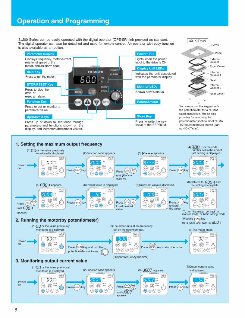
Operation and Programming
5
Press to run the motor.
Press to stop thedrive orreset an alarm.
Lights when the powerinput to the drive is ON.
Indicates the unit associatedwith the parameter display.
Press up or down to sequence throughparameters and functions shown on thedisplay, and increment/decrement values.
Press to set or monitor aparameter value.
Parameter Display
Displays frequency, motor current,rotational speed of themotor, and an alarm code.
SJ200 Series can be easily operated with the digital operator (OPE-SRmini) provided as standard.The digital operator can also be detached and used for remote-control. An operator with copy functionis also available as an option.
RUN Key
STOP/RESET Key
Function Key
Up/Down Keys
Power LED
Display Unit LEDs
Monitor LEDs
Shows drive's status.
Potentiometer
Store Key
Press to write the newvalue to the EEPROM.
Panel
Screw
ExternalGasket
Front Cover
InternalGasket 1
Seal
InternalGasket 2
Rear Cover
You can mount the keypad with
the potentiometer for a NEMA1
rated installation. The kit also
provides for removing the
potentiometer knob to meet NEMA
4X requirements,as shown (part
no.4X-KITmini).
4X-KITmini
FUNC
FUNC
FUNC
FUNC
STR
FUNC
STOPRESETRUN
FUNC
(1) or the value previously
monitored is displayed.
(1) or the value previouslymonitored is displayed.
(1) or the value previously
monitored is displayed.
(2)The motor runs at the frequency
set by the potentiometer. (3)The motor stops.
(2)Function code appears. (3) appears.
(5) appears. (6)Preset value is displayed. (7)Newly set value is displayed.(8)Returns to and
the setting is complete.
(4) or the codenumber set in the end oflast setting is displayed.
Poweron
Poweron
Poweron
Press
untilappears.
Press
to set desiredvalue.
Press
until
appears.
Press key.
Press key. Press key.
Press keyto storethe value.
*To run the motor, go back tomonitor mode or basic setting mode.
*Pressing key
for a while and back to
Press key to stop the motor.Press key and turn the
potentiometer clockwise.
Press key. Press key.
(2)Function code appears. appears.
(4)Output current value
is displayed.
Press
untilappears.
1. Setting the maximum output frequency
2. Running the motor(by potentiometer)
3. Monitoring output current value
(3)
(Output frequency monitor)
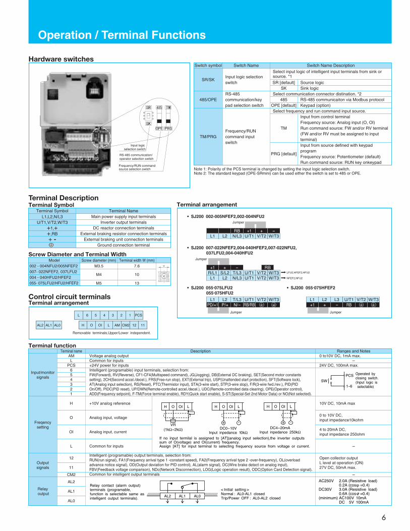
Input logic selection switch
RS-485 communication/operator selection switch
Frequency/RUN command source selection switch
Operation / Terminal Functions
6
Hardware switchesSwitch symbol
SR/SK
485/OPE
TM/PRG
Input logic selectionswitch
Select input logic of intelligent input terminals from sink orsource. *1
SR [default]SK
Source logicSink logic
RS-485communication/keypad selection switch
Frequency/RUNcommand inputswitch
Select communication connector distination. *2485
OPE [default]RS-485 communicaiton via Modbus protocolKeypad (option)
Select frequency and run command input source.
TM
Input from control terminalFrequency source: Analog input (O, OI)Run command source: FW and/or RV terminal(FW and/or RV must be assigned to inputterminal)
PRG [default]
Input from source defined with keypadprogramFrequency source: Potentiometer (default)Run command source: RUN key onkeypad
Switch Name Switch Name Description
Terminal DescriptionTerminal Symbol
Terminal SymbolL1,L2,N/L3
U/T1,V/T2,W/T3+1,++,RB+ -
Main power supply input terminalsInverter output terminals
DC reactor connection terminalsExternal braking resistor connection terminals
External braking unit connection terminalsGround connection terminal
Terminal Name
RB
• SJ200 002-005NFEF2,002-004NFU2
• SJ200 007-022NFEF2,004-040HFEF2,007-022NFU2,037LFU2,004-040HFU2
RB +1 + -
L1 L2 N/L3 U/T1 V/T2 W/T3
Jumper
RB/RBPD/+1 P/+ N/-
L1 L2 T/L3 U/T1 V/T2 W/T3
Jumper
+1 + -
R/L1 S/L2 T/L3 U/T1 V/T2 W/T3
L1 L2 N/L3 U/T1 V/T2 W/T3
Jumper
• SJ200 055.075LFU2055.075HFU2
RB+1 + -
L1 L2 L3 U/T1 V/T2 W/T3
Jumper
• SJ200 055.075HFEF2
LFU2,HFEF2,HFU2
NFEF2,NFU2
Model Screw diameter (mm)002 - 004NFU2/005NFEF2007- 022NFEF2, 037LFU2004 - 040HFU2/HFEF2055- 075LFU2/HFU2/HFEF2
M3.5
M4
M5
Terminal width W (mm)7.6
10
13
Screw Diameter and Terminal Width
Terminal arrangement
Control circuit terminalsTerminal arrangement
L 6 5 4 3 2 1 PCS
1112CM2AMLOIOHAL0AL1AL2
Removable terminals,Upper/Lower independent.
Terminal functionTerminal name Description Ranges and Notes
Input/monitorsignals
AML
PCS654321
Freqencysetting
Output signals
12
11
CM2
Relayoutput
AL2
AL1
AL0
H
O
OI
L
+10V analog reference
Analog input, voltage
Analog input, current
Common for inputs
Intelligent (programable) output terminals, selection from:RUN(run signal), FA1(Frequency arrival type 1 -constant speed), FA2(Frequency arrival type 2 -over-frequency), OL(overloadadvance notice signal), OD(Output deviation for PID control), AL(alarm signal), DC(Wire brake detect on analog input),FBV(Feedback voltage comparison), NDc(Network Disconnection), LOG(Logic operation result), ODC(Option Card Detection signal).
Open collector outputL level at operation (ON)27V DC, 50mA max.
-Common for intelligent output terminals
10V DC, 10mA max
0 to 10V DC, input impedance10kohm
4 to 20mA DC,input impedance 250ohm
-
Voltage analog outputCommon for inputs+24V power for inputs
0 to10V DC, 1mA max.-
24V DC, 100mA max.Intelligent (programable) input terminals, selection from:FW(Forward), RV(Reverse), CF1-CF4(Multispeed command), JG(Jogging), DB(External DC braking), SET(Second motor constantssetting), 2CH(Second accel./decel.), FRS(Free-run stop), EXT(External trip), USP(Unattended start protection), SFT(Software lock),AT(Analog input selection), RS(Reset), PTC(Thermistor input), STA(3-wire start), STP(3-wire stop), F/R(3-wire fwd./rev.), PID(PIDOn/Off), PIDC(PID reset), UP/DWN(Remote-controlled accel./decel.), UDC(Remote-controlled data clearing), OPE(Operator control),ADD(Frequency setpoint), F-TM(Force terminal enable), RDY(Quick start enable), S-ST(Special-Set 2nd Motor Data) or NO(Not selected).
(1kΩ-2kΩ)VR
H O OI L
DC0-10VInput inpedance 10kΩ
H O OI L
+ -
DC4-20mAInput inpedance 250kΩ
H O OI L
+ -
If no input termilal is assigned to [AT](analog input selection),the inverter outputssum of O(voltage) and OI(current) frequency.Assign [AT] for input terminal to selecting frequency source from voltage or current.
Relay contact (alarm output)terminals (programable,function is selectable same asintelligent output terminals).
< Initial setting >Normal : AL0-AL1 closedTrip/Power OFF : AL0-AL2 closed
AL0AL1AL2
AC250V 2.0A (Resistive load)0.2A (cos =0.4)
DC30V 3.0A (Resistive load)0.6A (cos =0.4)
(minimum) AC100V 10mADC 5V 100mA
SWPCS
1-6
Operated by closing switch.(Input logic is selectable)
Note 1: Polarity of the PCS terminal is changed by setting the input logic selection switch.Note 2: The standard keypad (OPE-SRmini) can be used either the switch is set to 485 or OPE.
-

XX
XX
XXXXXXXXXXXXXXXX
Function List
7
Monitoring and main profile parameters
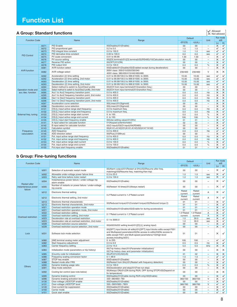
A Group: Standard functions
: Allowed[ X: Not allowed ]Lo Hi
X
XXXXXXXX
The parameter tables in this chapter have a column titled "Run Mode Edit." An Ex mark x means the parameter cannot be edited; a Checkmark means the parameter can be edited. The table example to the right contains two adjacent marks "x ". These two marks (that canalso be "xx" or " ") correspond to low-access or high-access levels to Run Mode edits (note Lo and Hi in column heading).
Function Code Name Range Default UnitRun mode edit
Monitor
Main ProfileParameters
F001F002F202F003F203F004
d001d002d003d004
d005
d006
d007d013d016d017d080d081d082d083
Output frequency monitorOutput current monitorRotation direction monitorProcess variable, PID feedback monitor
Intelligent input terminal status
Intelligent output terminal status
Scaled output frequency monitorOutput voltage monitorCumulative operation RUN time monitorCumulative power-on time monitorTrip counterTrip monitor 1Trip monitor 2Trip monitor 3Output frequency settingAcceleration time (1) settingAcceleration time (2) settingDeceleration time (1) settingDeceleration time (2) settingKeypad Run key routing
----
-
-
--------
HzA--
-
-
-Vhrhr
times---
----
-
-
--------
0.0/start freq. to 400.00.01 to 99.99/100.0 to 999.9/1000. to 3000.0.01 to 99.99/100.0 to 999.9/1000. to 3000.0.01 to 99.99/100.0 to 999.9/1000. to 3000.0.01 to 99.99/100.0 to 999.9/1000. to 3000.00(Forward)/01(Reverse)
0.010.010.010.010.000
Hzsecsecsecsec-
Expanded functions
A--b--C--H--P--
A Group: Standard functionsb Group: Fine-tuning functionsC Group: Intelligent terminal functionsH Group: Motor constants functionsP Group: Expansion Card Functions
6 5 4 3
ONOFF
2 1
AL
ONOFF
12 11
e.g. :1,2 : ON3,4,5,6 : OFF
e.g. :11,12 : ONAL : OFF
----
-
-
--------
X
Basic setting
A001A201A002A202A003A203A004A204
Frequency source settingFrequency source setting, 2nd motorRun command source settingRun command source setting, 2nd motorBase frequency settingBase frequency setting, 2nd motorMaximum frequency settingMaximum frequency setting, 2nd motor
00(Keypad potentiometer)/01(Control terminal)/02(Function F001 setting)/03(RS485)/10(Calculation result)
01(Control terminal)/02(Run key on keypad)/03(RS485)
30 to maximum freq.30 to maximum freq.30 to 40030 to 400
0101010150.50.50.50.
0000020260.60.60.60.
----HzHzHzHz
XXXXXXXX
Analog input setting
A005A011A012A013A014A015A016
[AT] selection[O]-[L] input active range start frequency[O]-[L] input active range end frequency[O]-[L] input active range start voltage[O]-[L] input active range end voltage[O]-[L] input start frequency enableExternal frequency filter time constant
00(O/OI)/01(disable)/02(O/VR)/03(OI/VR)0.0 to maximum freq.0.0 to maximum freq.0 to 1000 to 10000(use set value)/01(use 0 Hz)1 to 17
000.00.
0.0100.018.
000.00.
0.0100.018.
-HzHz%%--
XXXXXXX
Multi-speed andjogging
A020 -A035A220A038A039
Multi-speed frequency setting (0-15)
Multi-speed frequency (2nd), 0Jog frequency settingJog stop mode
0.0/start freq. to maximum freq.
0.0/start freq. to maximum freq.0.00/start freq. to 9.9900(free-run stop)/01(deceleration and stop)/02(DC braking)
0.0
0.01.0000
0.0
0.01.0000
Hz
HzHz-
V/f Characteristic
DC braking
Frequency limit andjump frequency
A042A242A043A243A044A244A045A245A046A246A047A247A051A052A053A054A055A056A061A261A062A262A063A064A065A066A067A068
Manual torque boost valueManual torque boost value, 2nd motorManual torque boost frequency adjustmentManual torque boost frequency adjustment, 2nd motorV/f characteristic curve selectionV/f characteristic curve selection, 2nd motorV/f gain settingV/f gain setting, 2nd motoriSLV voltage compensation gainiSLV voltage compensation gain,2nd motoriSLV slip compensation gainiSLV slip compensation gain, 2nd motorDC braking enableDC braking frequency settingDC braking wait timeDC braking force during decelerationDC braking time for decelerationDC braking / edge or level detection for [DB] inputFrequency upper limit settingFrequency upper limit setting, 2nd motorFrequency lower limit settingFrequency lower limit setting, 2nd motorJump (center) frequency setting 1Jump (hysteresis) frequency setting 1Jump (center) frequency setting 2Jump (hysteresis) frequency setting 2Jump (center) frequency setting 3Jump (hysteresis) frequency setting 3
5.00.03.00.00202
100.100.100.100.100.100.000.50.00.
0.0010.00.00.00.00.00.50.00.50.00.5
0.00.03.00.00202
100.100.100.100.100.100.000.50.00.
0.0010.00.00.00.00.00.50.00.50.00.5
%%%%--%%%%%%-Hzsec%
sec-HzHzHzHzHzHzHzHzHzHz
0.0 to 20.00.0 to 20.00.0 to 50.00.0 to 50.000(VC)/01(Reduced torque)/02(I-SLV)00(VC)/01(Reduced torque)/02(I-SLV)20 to 10020 to 1000 to 2550 to 2550 to 2550 to 25500(Disable)/01(Enable)Start freq. to 60.00.0 to 5.00. to 100.0.0 to 60.000(Edge)/01(Level)0.0/Freq. lower limit setting to maximum freq.0.0/Freq. lower limit setting (2nd) to maximum freq. (2nd)0.0/Start freq. to freq. upper limit setting0.0/Start freq. (2nd) to freq. upper limit setting (2nd)0.0 to 400.0.0 to 10.00.0 to 400.0.0 to 10.00.0 to 400.0.0 to 10.0
X
Run modeeditFunction Code Name Range
Default
-EF(CE) -U(UL)Unit
Lo Hi
0.0 to 400.00.0 to 999.9F(Forward)/o(Stop)/r(Reverse)0.00 to 99.99/100.0 to 999.9/1000. to 9999.
0.00 to 99.99/100.0 to 999.9/1000. to 9999./1000 to 9999(10000 to 99999)0.0 to 600.00. to 9999./1000 to 9999/10000 to 999900. to 9999./1000 to 9999/10000 to 999910. to 9999.
Displays trip event information
Function List
8
A Group: Standard functions
b Group: Fine-tuning functions
: Allowed[ X: Not allowed ]
PID Control
AVR function
Operation mode andacc./dec. function
External freq. tuning
Frequencycaluculation
A071A072A073A074A075A076A077A078A081
A082
A092A292A093A293A094A294A095A295A096A296A097A098A101A102A103A104A105A141A142A143A145A146A151A152A153A154A155
PID EnablePID proportional gainPID integral time constantPID derivative time constantPV scale conversionPV source settingReverse PID actionPID output limitAVR function select
AVR voltage select
Acceleration (2) time settingAcceleration (2) time setting, 2nd motorDeceleration (2) time settingDeceleration (2) time setting, 2nd motorSelect method to switch to Acc2/Dec2 profileSelect method to switch to Acc2/Dec2 profile, 2nd motorAcc1 to Acc2 frequency transition pointAcc1 to Acc2 frequency transition point, 2nd motorDec1 to Dec2 frequency transition pointDec1 to Dec2 frequency transition point, 2nd motorAcceleration curve selectionDeceleration curve selection[OI]-[L] input active range start frequency[OI]-[L] input active range end frequency[OI]-[L] input active range start current[OI]-[L] input active range end current[OI]-[L] input start frequency enableA input select for calculate functionB input select for calculate functionCalculation symbolADD frequencyADD direction selectPot. input active range start frequencyPot. input active range end frequencyPot. input active range start currentPot. input active range end currentPot.input start frequency enable
00(Disable)/01(Enable)0.2 to 5.00.0 to 150.00.00 to 100.00.01 to 99.9900([OI] terminal)/01([O] terminal)/02(RS485)/10(Calculation result)00(OFF)/01(ON)0.0 to 100.000(Enable)/01(Disable)/02(Enabled except during deceleration)200V class: 200/215/220/230/240400V class: 380/400/415/440/460/4800.01 to 99.99/100.0 to 999.9/1000. to 3000.0.01 to 99.99/100.0 to 999.9/1000. to 3000.0.01 to 99.99/100.0 to 999.9/1000. to 3000.0.01 to 99.99/100.0 to 999.9/1000. to 3000.00(2CH from input terminal)/01(transition freq.)00(2CH from input terminal)/01(transition freq.)0.0 to 400.00.0 to 400.00.0 to 400.00.0 to 400.000(Linear)/01(Sigmoid)00(Linear)/01(Sigmoid)0.0 to maximum freq.0.0 to maximum freq.0. to 100.0. to 100.00(Use setting value)/01(0Hz)01(Keypad potentiometer)02(O input)/03(OI input)/04(RS485)00(A141+A142)/01(A141-A142)/02(A141*A142)0.0 to 400.000(Plus),01(Minus)0.0 to 400.00.0 to 400.00.0 to 100.00.0 to 100.000(Disable)/01(Enable)
001.01.00.01.0000000.000
230/400
15.0015.0015.0015.00
00000.00.00.00.000000.00.00.0100.010203000.0000.00.00.00.001
001.01.00.0
1.0000000.000
230/460
15.0015.0015.0015.00
00000.00.00.00.000000.00.00.0
100.010203000.0000.00.00.00.001
--
secsec---%-
V
secsecsecsec--HzHzHzHz--HzHz%%----Hz-HzHz%%-
X
XXXXX
X
XXXXXXXXXXXXXXXX
XXXXXX
Run modeeditFunction Code Name Range
Default
-EF(CE) -U(UL)Unit
Lo Hi
X
X
XXXXXXXX
Restart afterinstantaneous power
failure
b001
b002b003
b004
b005
b012
b212
b013b213
Selection of automatic restart mode
Allowable under-voltage power failure timeRetry wait time before motor restartInstantaneous power failure / under-voltage tripalarm enableNumber of restarts on power failure / under-voltagetrip events
Electronic thermal setting
Electronic thermal setting, 2nd motor
Electronic thermal characteristicElectronic thermal characteristic, 2nd motor
00(Alarm output)/01(Restart at 0Hz)/02(Resume after freq.matching)/03(Resume freq. matching then trip)0.3 to 25.00.3 to 100.0
00(Disable)/01(Enable)
00(Restart 16 times)/01(Always restart)
0.2*Rated current to 1.2*Rated current
00(Reduced torque)/01(Constant torque)/02(Reduced torque 2)
00
1.01.0
00
00
RatedcurrentRatedcurrent
0101
00
1.01.0
00
00
RatedcurrentRatedcurrent
0101
-
secsec
-
-
A
A
--
X
XX
X
X
X
X
XX
Overload restriction
b021b221b022b222b023b223b028b228
Overload restriction operation modeOverload restriction operation mode, 2nd motorOverload restriction settingOverload restriction setting, 2nd motorDeceleration rate at overload restrictionDeceleration rate at overload restriction, 2nd motorOverload restriction source selectionOverload restriction source selection, 2nd motor
00(Disable)/01(Enable)/02(Enable for during acceleration)
0.1*Rated current to 1.5*Rated current
0.1 to 3000.0
00(b022/b222 setting level)/01([O]-[L] analog input)
0101
1.5*Ratedcurrent
1.01.00000
0101
1.5*Ratedcurrent
30.030.00000
--AA
secsec--
XXXXXXXX
Run modeeditFunction Code Name Range
Default
-EF(CE) -U(UL)Unit
Lo Hi
Lock b031 Software lock mode selection
00([SFT] input blocks all edits)/01([SFT] input blocks edits except F001and Multispeed parameters/02(No access to edits)/03(No access toedits except F001 and Multi-speed parameters)/10(High-levelaccess,including b031)
01 01 - X
Others
b080b082b083
b084
b085b086b087b088b090b091
b092
b095b096b130b131b140b150b151
[AM] terminal analog meter adjustmentStart frequency adjustmentCarrier frequency setting
Initialization mode (parameters or trip history)
]Country code for initializationFrequency scaling conversion factorSTOP key enableRestart mode after FRSDynamic braking usage ratioStop mode selection
Cooling fan control (see note below)
Dynamic braking controlDynamic braking activation levelOver-voltage LADSTOP enableOver-voltage LADSTOP levelOver-current trip suppressionCarrier modeQuick start enable
0. to 255.0.5 to 9.92.0 to 14.000(Trip history clear)/01(Parameter initialization)/02(Trip history clear and parameter initialization)00(JP)/01(CE)/02(US)0.1~99.900(Enable)/01(Disable)00(Restart from 0Hz)/01(Restart with frequency detection)0.0 to 100.000(Deceleration and stop)/01(Free-run stop)00(Always ON)/01(ON during RUN, OFF during STOP)/02(Depend onfin temperature)00(Disable)/01(Enable during RUN only)/02(Enable)330~380/660~76000(Disable)/01(Enable)330~390V/660~780V00(Disable)/01(Enable)00(Disable)/01(Enable)00(Disable)/01(Enable)
100.0.55.0
00
011.000000.000
00
00360/720
00380/760
000000
100.0.55.0
00
021.000000.000
00
00360/720
00380/760
000000
-HzkHz
-
----%-
-
-V-V---
XX
X
X
XXXX
X
XXX
XX
X
X
X
X
X
Function List
9
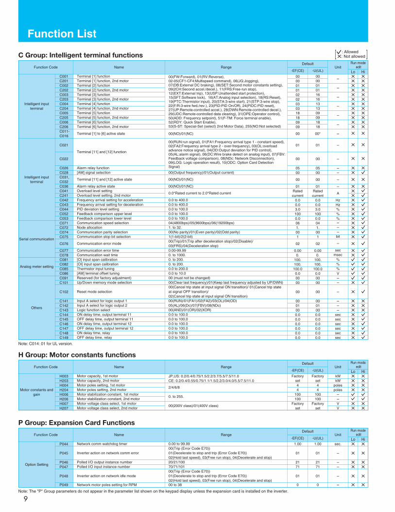
C Group: Intelligent terminal functions
H Group: Motor constants functions
: Allowed[ X: Not allowed ]
Note: C014: 01 for UL version.
P Group: Expansion Card Functions
Note: The "P" Group parameters do not appear in the parameter list shown on the keypad display unless the expansion card is installed on the inverter.
Run modeeditFunction Code Name Range
Default
-EF(CE) -U(UL)Unit
Lo
Intelligent inputterminal
C001C201C002C202C003C203C004C204C005C205C006C206
Terminal [1] functionTerminal [1] function, 2nd motorTerminal [2] functionTerminal [2] function, 2nd motorTerminal [3] functionTerminal [3] function, 2nd motorTerminal [4] functionTerminal [4] function, 2nd motorTerminal [5] functionTerminal [5] function, 2nd motorTerminal [6] functionTerminal [6] function, 2nd motor
00(FW:Forward), 01(RV:Reverse), 02-05(CF1-CF4:Multispeed command), 06(JG:Jogging),07(DB:External DC braking), 08(SET:Second motor constants setting), 09(2CH:Second accel./decel.), 11(FRS:Free-run stop),12(EXT:External trip), 13(USP:Unattended start protection),15(SFT:Software lock), 16(AT:Analog input selection), 18(RS:Reset),19(PTC:Thermistor input), 20(STA:3-wire start), 21(STP:3-wire stop),22(F/R:3-wire fwd./rev.), 23(PID:PID On/Off), 24(PIDC:PID reset), 27(UP:Remote-controlled accel.), 28(DWN:Remote-controlled decel.),29(UDC:Remote-controlled data clearing), 31(OPE:Operator control),50(ADD: Frequency setpoint), 51(F-TM: Force terminal enable), 52(RDY: Quick Start Enable), 53(S-ST: Special-Set (select) 2nd Motor Data), 255(NO:Not selected)
000001010202030318180909
000001011616131309091818
-
-
-
-
-
-
XXXXXXXXXXXX
XXXXXXXXXXXX
Hi
C011-C016
Terminal [1] to [6] active state 00(NO)/01(NC) 00 00* - X X
C021
C022
Terminal [11] and [12] function
00(RUN:run signal), 01(FA1:Frequency arrival type 1 - constant speed),02(FA2:Frequency arrival type 2 - over-frequency), 03(OL:overloadadvance notice signal), 04(OD:Output deviation for PID control), 05(AL:alarm signal), 06(DC:Wire brake detect on analog input), 07(FBV:Feedback voltage comparison), 08(NDc: Network Disconnection),09(LOG: Logic operation result), 10(ODC: Option Card DetectionSignal)
01
00
01
00
-
-
X X
Intelligent inputterminal
C026C028C031,C032C036C041C241C042C043C044C052C053
Alarm relay function[AM] signal selection
Terminal [11] and [12] active state
Alarm relay active stateOverload level settingOverload level setting, 2nd motorFrequency arrival setting for accelerationFrequency arrival setting for decelerationPID deviation level settingFeedback comparison upper levelFeedback comparison lower level
0500
00
01Ratedcurrent
0.00.03.01000.0
0500
00
01Ratedcurrent
0.00.03.01000.0
--
-
-
A
HzHz%%%
00(Output frequency)/01(Output current)
00(NO)/01(NC)
00(NO)/01(NC)
0.0*Rated current to 2.0*Rated current
0.0 to 400.00.0 to 400.00.0 to 100.00.0 to 100.00.0 to 100.0
X X
XX
X
XXXXXXXX
X
X
X
Serial communication
C071C072C074C075
C076
C077C078
Communication speed selectionNode allocationCommunication parity selectionCommunication stop bit selection
Communication error mode
Communication error timeCommunication wait time
04(4800bps)/05(9600bps)/06(19200bps)1. to 32.00(No parity)/01(Even parity)/02(Odd parity)1(1-bit)/2(2-bit)00(Trip)/01(Trip after deceleration stop)/02(Disable)/03(FRS)/04(Deceleration stop)0.00-99.990. to 1000.
061.001
02
0.000.
041.001
02
0.000.
---bit
-
secmsec
XXXX
X
XX
Analog meter setting
C081C082C085C086
0. to 200.0. to 200.0.0 to 200.00.0 to 10.0
[O] input span calibration[OI] input span calibrationThermistor input tuning[AM] terminal offset tuning
100.100.100.00.0
100.100.
100.00.0
%%%V
00 (must not be changed)00(Clear last frequency)/01(Keep last frequency adjusted by UP/DWN)00(Cancel trip state at input signal ON transition)/ 01(Cancel trip stateat signal OFF transition)/02(Cancel trip state at input signal ON transition)00(RUN)/01(FA1)/02(FA2)/03(OL)/04(OD)05(AL)/06(Dc)/07(FBV)/08(NDc)00(AND)/01(OR)/02(XOR)0.0 to 100.00.0 to 100.00.0 to 100.00.0 to 100.00.0 to 100.00.0 to 100.0
Others
C091C101
C102
C141C142C143C144C145C146C147C148C149
Reserved (for factory adjustment)Up/Down memory mode selection
Reset mode selection
Input A select for logic output 1Input A select for logic output 2Logic function selectON delay time, output terminal 11OFF delay time, output terminal 11ON delay time, output terminal 12OFF delay time, output terminal 12ON delay time, relayOFF delay time, relay
0000
00
0001000.00.00.00.00.00.0
0000
00
0001000.00.00.00.00.00.0
--
-
---
secsecsecsecsecsec
X
X
XXXXXXXXX
XXX
Motor constants andgain
H003H203H004H204H006H206H007H207
Motor capacity, 1st motorMotor capacity, 2nd motorMotor poles setting, 1st motorMotor poles setting, 2nd motorMotor stabilization constant, 1st motorMotor stabilization constant, 2nd motorMotor voltage class select, 1st motorMotor voltage class select, 2nd motor
JP,US: 0.2/0.4/0.75/1.5/2.2/3.7/5.5/7.5/11.0CE: 0.2/0.4/0.55/0.75/1.1/1.5/2.2/3.0/4.0/5.5/7.5/11.0
2/4/6/8
0. to 255.
00(200V class)/01(400V class)
Factoryset44
100100
Factoryset
Factoryset44
100100
Factoryset
kWkW
polespoles--VV
Run modeeditFunction Code Name Range
Default
-EF(CE) -U(UL)Unit
Lo HiXXXX
XX
XXXX
XX
Option Setting
P044
P045
P046P047
P048
P049
Network comm watchdog timer
Inverter action on network comm error
Polled I/O output instance numberPolled I/O input instance number
Inverter action on network idle mode
Network motor poles setting for RPM
0.00 to 99.9900(Trip (Error Code E70))01(Decelerate to stop and trip (Error Code E70))02(Hold last speed), 03(Free run stop), 04(Decelerate and stop)20/21/10070/71/10100(Trip (Error Code E70))01(Decelerate to stop and trip (Error Code E70))02(Hold last speed), 03(Free run stop), 04(Decelerate and stop)00 to 38
1.00
01
2171
01
0
1.00
01
2171
01
0
sec.
-
--
-
-
Run modeeditFunction Code Name Range
Default
-EF(CE) -U(UL)Unit
Lo HiX
X
XX
X
X
X
X
XX
X
X

OC.Drive
OC.Decel
OC.Accel
Over.C
Over.L
OL.BRD
Over.V
EEPROM
EEPROM
CPU
COMM.ERR
Under.V
EXTERNAL
USP
GND.Flt
OV.SRC
OH FIN
GA
TH
COMM
Protective Functions
10
Name
Over current
Overloadprotection *1
Braking resistor overload
Over voltage protection
EEPROM error *2,3
Under-voltage error
CPU error
External trip
USP *4
Ground fault *5
Input over-voltage
Inverter thermal trip
Gate array error
Thermistor
Communications error
Cause(s) Display on digitaloperator
The inverter output was short-circuited, or the motor shaft is locked or has a heavyload. These conditions cause excessive current for the inverter, so the inverteroutput is turned OFF.
When a motor overload is detected by the electronic thermal function, the inverter trips and turns OFFits output.When the regenerative braking resistor exceeds the usage time allowance or sage ratio, the invertertrips and turns OFF its output to the motor.
When the DC bus voltage exceeds a threshold, due to regenerative energy from the motor.
When the built-in EEPROM memory has problems due to noise or excessive temperature, the invertertrips and turns OFF its output to the motor.A decrease of internal DC bus voltage below a threshold results in a control circuit fault. This conditioncan also generate excessive motor heat or cause low torque. The inverter trips and turns OFF itsoutput.
A malfunction in the built-in CPU has occurred, so the inverter trips and turns OFF its output to themotor.
A signal on an intelligent input terminal configured as EXT has occurred. The inverter trips and turnsOFF the output to the motor.When the Unattended Start Protection (USP) is enabled, an error occurred when power is appliedwhile a Run signal is present. The inverter trips and does not go into Run Mode until the error iscleared.The inverter is protected by the detection of ground faults between the inverter output and the motorduring powerup tests. This feature protects the inverter, and does not protect humans.When the input voltage is higher than the specified value, it is detected 100 seconds after powerupand the inverter trips and turns OFF its output.When the inverter internal temperature is above the threshold, the thermal sensor in the invertermodule detects the excessive temperature of the power devices and trips, turning the inverter outputOFF.
An internal inverter error has occurred in communications between the CPU and gate array IC.
When a thermistor is connected to terminals [PTC] and [CM1] and the inverter has sensed thetemperature is too high, the inverter trips and turns OFF the output.
The inverter's watchdog timer for the communications network has timed out.
While atconstant speedDuringdecelerationDuringacceleration
Others
Display on remoteoperator/copy unit
Error Codes
Error codeOutput frequency
at trip pointMotor currentat trip point
Voltage betweenP(+) and N(-) at trip point
Cumulative inverterRUN time at trip point
Cumulative power-ontime at trip point
1 2 1 2 1 2 1 2 1 2
1 2
How to access the details about the present fault
Note 1: Reset operations acceptable 10 seconds after the trip.Note 2: If an EEPROM error (E08) occurs, be sure to confirm the parameter data values are still correct.Note 3: EEPROM error may occer at power-on after shutting down the power while copying data with remote operator or initializing data. Shut down the power after completing copy or
initialization.Note 4: USP error occures at reseting trip after under-voltage error (E09) if USP is enabled. Reset once more to recover.Note 5: Ground fault error (E14) cannot be released with resetting. Shut the power and check wiring.
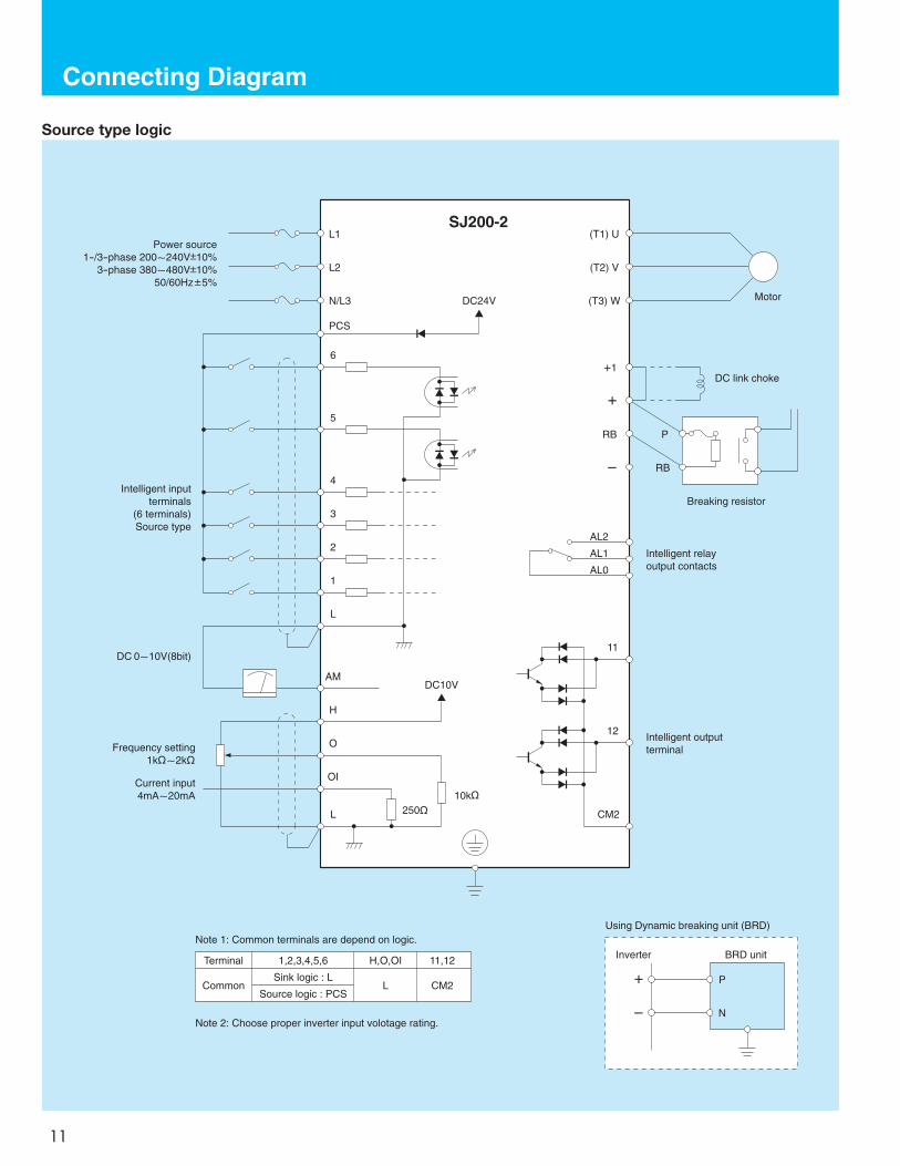
Connecting Diagram
11
AL2
AL1
AL0
L1
N/L3
L2
(T1) U
(T3) W
(T2) V
PCS
6
5
4
3
2
1
L
AM
H
O
OI
L
DC24V
DC10V
11
12
CM2
+1
+
RB
ー
DC link choke
P
RB
Motor
Intelligent relayoutput contacts
Intelligent outputterminal
Current input4mA~20mA
Breaking resistor
SJ200-2
Intelligent inputterminals
(6 terminals)Source type
DC 0~10V(8bit)
Power source1-/3-phase 200~240V 10%
3-phase 380~480V 10%50/60Hz 5%
Terminal 1,2,3,4,5,6 H,O,OI 11,12
CommonSink logic : L
L CM2Source logic : PCS
Note 1: Common terminals are depend on logic.
Note 2: Choose proper inverter input volotage rating.
P
N
+
ー
BRD unitInverter
Using Dynamic breaking unit (BRD)
10k 250
Frequency setting1k ~2k
Source type logic
Wiring and Accessories
12
L1 L2 L3
U(T1) V(T2) W(T3)
+1
+
RBー
IM
Power Supply
Fuse
Inverter
Motor
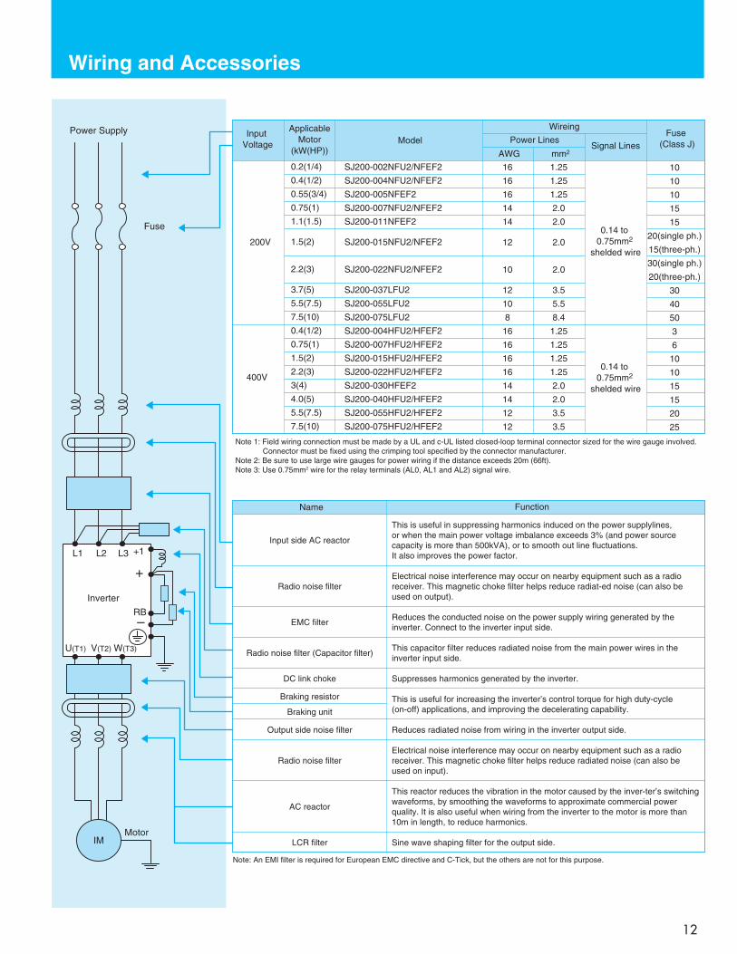
Note 1: Field wiring connection must be made by a UL and c-UL listed closed-loop terminal connector sized for the wire gauge involved. Connector must be fixed using the crimping tool specified by the connector manufacturer. Note 2: Be sure to use large wire gauges for power wiring if the distance exceeds 20m (66ft). Note 3: Use 0.75mm2 wire for the relay terminals (AL0, AL1 and AL2) signal wire.
Name Function
This is useful in suppressing harmonics induced on the power supplylines, or when the main power voltage imbalance exceeds 3% (and power source capacity is more than 500kVA), or to smooth out line fluctuations. It also improves the power factor.
Electrical noise interference may occur on nearby equipment such as a radio receiver. This magnetic choke filter helps reduce radiat-ed noise (can also be used on output).
Reduces the conducted noise on the power supply wiring generated by theinverter. Connect to the inverter input side.
This capacitor filter reduces radiated noise from the main power wires in the inverter input side.
Suppresses harmonics generated by the inverter.
This is useful for increasing the inverter’s control torque for high duty-cycle (on-off) applications, and improving the decelerating capability.
Reduces radiated noise from wiring in the inverter output side.
Electrical noise interference may occur on nearby equipment such as a radio receiver. This magnetic choke filter helps reduce radiated noise (can also be used on input).
This reactor reduces the vibration in the motor caused by the inver-ter’s switching waveforms, by smoothing the waveforms to approximate commercial power quality. It is also useful when wiring from the inverter to the motor is more than 10m in length, to reduce harmonics.
Sine wave shaping filter for the output side.
Input side AC reactor
Radio noise filter
EMC filter
Radio noise filter (Capacitor filter)
DC link choke
Braking resistor
Braking unit
Output side noise filter
Radio noise filter
AC reactor
LCR filter
Note: An EMI filter is required for European EMC directive and C-Tick, but the others are not for this purpose.
Input Voltage
Applicable Motor
(kW(HP))Model
Wireing
Power Lines
AWG mm2 Signal Lines
Fuse (Class J)
0.2(1/4)
0.4(1/2)
0.55(3/4)
0.75(1)
1.1(1.5)
1.5(2)
2.2(3)
3.7(5)
5.5(7.5)
7.5(10)
0.4(1/2)
0.75(1)
1.5(2)
2.2(3)
3(4)
4.0(5)
5.5(7.5)
7.5(10)
SJ200-002NFU2/NFEF2
SJ200-004NFU2/NFEF2
SJ200-005NFEF2
SJ200-007NFU2/NFEF2
SJ200-011NFEF2
SJ200-015NFU2/NFEF2
SJ200-022NFU2/NFEF2
SJ200-037LFU2
SJ200-055LFU2
SJ200-075LFU2
SJ200-004HFU2/HFEF2
SJ200-007HFU2/HFEF2
SJ200-015HFU2/HFEF2
SJ200-022HFU2/HFEF2
SJ200-030HFEF2
SJ200-040HFU2/HFEF2
SJ200-055HFU2/HFEF2
SJ200-075HFU2/HFEF2
200V
400V
16
16
16
14
14
12
10
12
10
8
16
16
16
16
14
14
12
12
1.25
1.25
1.25
2.0
2.0
2.0
2.0
3.5
5.5
8.4
1.25
1.25
1.25
1.25
2.0
2.0
3.5
3.5
0.14 to 0.75mm2
shelded wire
0.14 to 0.75mm2
shelded wire
10
10
10
15
15
20(single ph.)
15(three-ph.)
30(single ph.)
20(three-ph.)
30
40
50
3
6
10
10
15
15
20
25
For Correct Operation
13
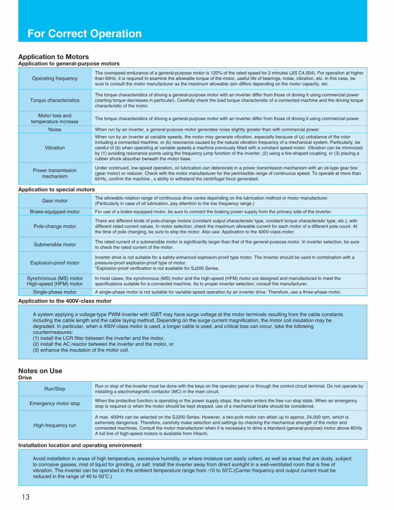
Application to Motors
The overspeed endurance of a general-purpose motor is 120% of the rated speed for 2 minutes (JIS C4,004). For operation at higherthan 60Hz, it is required to examine the allowable torque of the motor, useful life of bearings, noise, vibration, etc. In this case, besure to consult the motor manufacturer as the maximum allowable rpm differs depending on the motor capacity, etc.
The torque characteristics of driving a general-purpose motor with an inverter differ from those of driving it using commercial power(starting torque decreases in particular). Carefully check the load torque characteristic of a connected machine and the driving torquecharacteristic of the motor.
Application to general-purpose motors
Operating frequency
Torque characteristics
The torque characteristics of driving a general-purpose motor with an inverter differ from those of driving it using commercial power Motor loss and
temperature increase
When run by an inverter, a general-purpose motor generates noise slightly greater than with commercial power.NoiseWhen run by an inverter at variable speeds, the motor may generate vibration, especially because of (a) unbalance of the rotorincluding a connected machine, or (b) resonance caused by the natural vibration frequency of a mechanical system. Particularly, becareful of (b) when operating at variable speeds a machine previously fitted with a constant speed motor. Vibration can be minimizedby (1) avoiding resonance points using the frequency jump function of the inverter, (2) using a tire-shaped coupling, or (3) placing arubber shock absorber beneath the motor base.
Vibration
Under continued, low-speed operation, oil lubrication can deteriorate in a power transmission mechanism with an oil-type gear box(gear motor) or reducer. Check with the motor manufacturer for the permissible range of continuous speed. To operate at more than60Hz, confirm the machine , s ability to withstand the centrifugal force generated.
Power transmission mechanism
The allowable rotation range of continuous drive varies depending on the lubrication method or motor manufacturer.(Particularly in case of oil lubrication, pay attention to the low frequency range.)
Application to special motors
Gear motor
For use of a brake-equipped motor, be sure to connect the braking power supply from the primary side of the inverter.Brake-equipped motor
There are different kinds of pole-change motors (constant output characteristic type, constant torque characteristic type, etc.), withdifferent rated current values. In motor selection, check the maximum allowable current for each motor of a different pole count. Atthe time of pole changing, be sure to stop the motor. Also see: Application to the 400V-class motor.
Pole-change motor
The rated current of a submersible motor is significantly larger than that of the general-purpose motor. In inverter selection, be sureto check the rated current of the motor.Submersible motor
Inverter drive is not suitable for a safety-enhanced explosion-proof type motor. The inverter should be used in combination with apressure-proof explosion-proof type of motor.*Explosion-proof verification is not available for SJ200 Series.
Explosion-proof motor
In most cases, the synchronous (MS) motor and the high-speed (HFM) motor are designed and manufactured to meet thespecifications suitable for a connected machine. As to proper inverter selection, consult the manufacturer.
Synchronous (MS) motorHigh-speed (HFM) motor
A single-phase motor is not suitable for variable-speed operation by an inverter drive. Therefore, use a three-phase motor.Single-phase motor
Application to the 400V-class motor
A system applying a voltage-type PWM inverter with IGBT may have surge voltage at the motor terminals resulting from the cable constantsincluding the cable length and the cable laying method. Depending on the surge current magnification, the motor coil insulation may bedegraded. In particular, when a 400V-class motor is used, a longer cable is used, and critical loss can occur, take the followingcountermeasures:(1) install the LCR filter between the inverter and the motor,(2) install the AC reactor between the inverter and the motor, or(3) enhance the insulation of the motor coil.
Notes on UseDrive
Run or stop of the inverter must be done with the keys on the operator panel or through the control circuit terminal. Do not operate byinstalling a electromagnetic contactor (MC) in the main circuit.Run/Stop
When the protective function is operating or the power supply stops, the motor enters the free run stop state. When an emergencystop is required or when the motor should be kept stopped, use of a mechanical brake should be considered.Emergency motor stop
A max. 400Hz can be selected on the SJ200 Series. However, a two-pole motor can attain up to approx. 24,000 rpm, which isextremely dangerous. Therefore, carefully make selection and settings by checking the mechanical strength of the motor andconnected machines. Consult the motor manufacturer when it is necessary to drive a standard (general-purpose) motor above 60Hz.A full line of high-speed motors is available from Hitachi.
High-frequency run
Installation location and operating environment
Avoid installation in areas of high temperature, excessive humidity, or where moisture can easily collect, as well as areas that are dusty, subjectto corrosive gasses, mist of liquid for grinding, or salt. Install the inverter away from direct sunlight in a well-ventilated room that is free ofvibration. The inverter can be operated in the ambient temperature range from -10 to 50 C.(Carrier frequency and output current must bereduced in the range of 40 to 50 C.)
Unbalance factor of voltage =
VRS-(VRS+VST+VTR)/3(VRS+VST+VTR)/3
Max. line voltage (min.) - Mean line voltageMean line voltage x100
= x100 = x100 =1.5(%)205-202
202
For Correct Operation
14
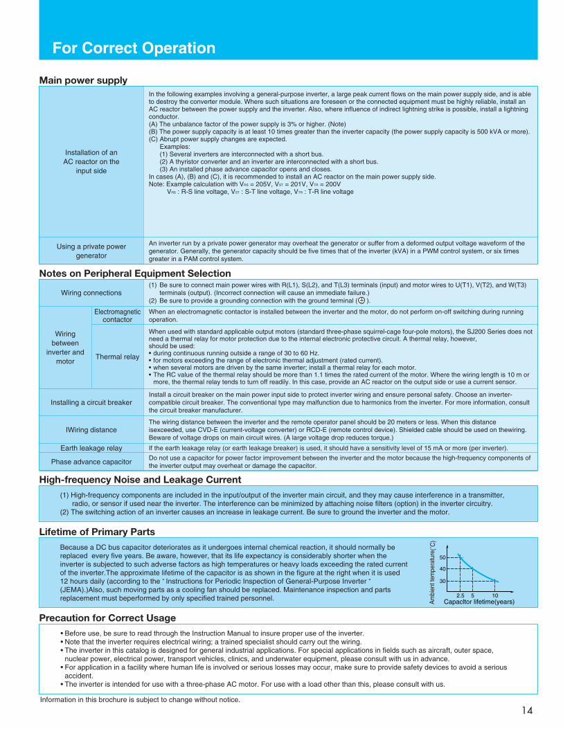
In the following examples involving a general-purpose inverter, a large peak current flows on the main power supply side, and is ableto destroy the converter module. Where such situations are foreseen or the connected equipment must be highly reliable, install anAC reactor between the power supply and the inverter. Also, where influence of indirect lightning strike is possible, install a lightningconductor.(A) The unbalance factor of the power supply is 3% or higher. (Note)(B) The power supply capacity is at least 10 times greater than the inverter capacity (the power supply capacity is 500 kVA or more).(C) Abrupt power supply changes are expected.
Examples:(1) Several inverters are interconnected with a short bus.(2) A thyristor converter and an inverter are interconnected with a short bus.(3) An installed phase advance capacitor opens and closes.
In cases (A), (B) and (C), it is recommended to install an AC reactor on the main power supply side.Note: Example calculation with VRS = 205V, VST = 201V, VTR = 200V
VRS : R-S line voltage, VST : S-T line voltage, VTR : T-R line voltage
An inverter run by a private power generator may overheat the generator or suffer from a deformed output voltage waveform of thegenerator. Generally, the generator capacity should be five times that of the inverter (kVA) in a PWM control system, or six timesgreater in a PAM control system.
Main power supply
Installation of anAC reactor on the
input side
Using a private powergenerator
(1) Be sure to connect main power wires with R(L1), S(L2), and T(L3) terminals (input) and motor wires to U(T1), V(T2), and W(T3)terminals (output). (Incorrect connection will cause an immediate failure.)
(2) Be sure to provide a grounding connection with the ground terminal ( ).
When an electromagnetic contactor is installed between the inverter and the motor, do not perform on-off switching during runningoperation.
When used with standard applicable output motors (standard three-phase squirrel-cage four-pole motors), the SJ200 Series does notneed a thermal relay for motor protection due to the internal electronic protective circuit. A thermal relay, however, should be used:• during continuous running outside a range of 30 to 60 Hz.• for motors exceeding the range of electronic thermal adjustment (rated current). • when several motors are driven by the same inverter; install a thermal relay for each motor. • The RC value of the thermal relay should be more than 1.1 times the rated current of the motor. Where the wiring length is 10 m or
more, the thermal relay tends to turn off readily. In this case, provide an AC reactor on the output side or use a current sensor.
Install a circuit breaker on the main power input side to protect inverter wiring and ensure personal safety. Choose an inverter-compatible circuit breaker. The conventional type may malfunction due to harmonics from the inverter. For more information, consultthe circuit breaker manufacturer.
Notes on Peripheral Equipment Selection
Wiring connections
Wiring between
inverter andmotor
Installing a circuit breaker
The wiring distance between the inverter and the remote operator panel should be 20 meters or less. When this distanceisexceeded, use CVD-E (current-voltage converter) or RCD-E (remote control device). Shielded cable should be used on thewiring.Beware of voltage drops on main circuit wires. (A large voltage drop reduces torque.)
IWiring distance
If the earth leakage relay (or earth leakage breaker) is used, it should have a sensitivity level of 15 mA or more (per inverter).Earth leakage relayDo not use a capacitor for power factor improvement between the inverter and the motor because the high-frequency components ofthe inverter output may overheat or damage the capacitor.Phase advance capacitor
Electromagneticcontactor
Thermal relay
High-frequency Noise and Leakage Current(1) High-frequency components are included in the input/output of the inverter main circuit, and they may cause interference in a transmitter,
radio, or sensor if used near the inverter. The interference can be minimized by attaching noise filters (option) in the inverter circuitry.(2) The switching action of an inverter causes an increase in leakage current. Be sure to ground the inverter and the motor.
Lifetime of Primary PartsBecause a DC bus capacitor deteriorates as it undergoes internal chemical reaction, it should normally bereplaced every five years. Be aware, however, that its life expectancy is considerably shorter when theinverter is subjected to such adverse factors as high temperatures or heavy loads exceeding the rated currentof the inverter.The approximate lifetime of the capacitor is as shown in the figure at the right when it is used12 hours daily (according to the " Instructions for Periodic Inspection of General-Purpose Inverter "(JEMA).)Also, such moving parts as a cooling fan should be replaced. Maintenance inspection and partsreplacement must beperformed by only specified trained personnel.
50
40
30
2.5 5 10Capacltor lifetime(years)A
mbi
ent t
empe
ratu
re(˚
C)
Precaution for Correct Usage• Before use, be sure to read through the Instruction Manual to insure proper use of the inverter.• Note that the inverter requires electrical wiring; a trained specialist should carry out the wiring.• The inverter in this catalog is designed for general industrial applications. For special applications in fields such as aircraft, outer space,
nuclear power, electrical power, transport vehicles, clinics, and underwater equipment, please consult with us in advance.• For application in a facility where human life is involved or serious losses may occur, make sure to provide safety devices to avoid a serious
accident.• The inverter is intended for use with a three-phase AC motor. For use with a load other than this, please consult with us.
Information in this brochure is subject to change without notice.

Printed in Japan (T) SM-E239S 0612


