
Lane Management System 1
Template based on IEEE Std 830-1998 for SRS. Modifications (content and ordering of information) have
been made by Betty H.C. Cheng, Michigan State University (chengb at chengb.cse.msu.edu)
Software Requirements Specification (SRS)
Project Lane Management System
Authors: Adam Pruim, Curtis Notarantonio, Jacob Heisey, Qiuning Ren, Matt Chebowski
Customer: Dr. S Ramesh, General Motors
Instructor: Dr. Cheng, Michigan State University
1 Introduction
This section provides a project scope and an overview of everything included in this
document. Also, the purpose of this project is outlined, and a list of all abbreviations and
definitions is provided.
1.1 Purpose
The purpose of this Software Requirements Specification (SRS) document is to provide a
detailed description of the functionalities of the Lane Management System (LMS). This
document covers each of the system’s intended features, as well as offers a preliminary
glimpse of the system’s User Interface (UI). The document also covers hardware,
software, and other technical dependencies.
This document is intended for the customer, Dr. Ramesh with General Motors, as well as
the course instructor, Dr. Cheng. Readers interested in a brief overview of the system
should focus on the rest of section 1, as well as section 2 of the document.
1.2 Scope
The product to be produced is titled Lane Management System. The Lane Management
System is representative of features that are implemented in next generation vehicles. The
application domain of the LMS is an embedded system for automotive systems. The LMS
is composed of two components. First the system has hardware that consists of 3 cameras
which will be placed on the left, center and right of the front of the vehicle. A toggle
switch for the system also exists inside the vehicle, allowing the driver to activate and
deactivate the system. Second the system has software which allows various components
of the system to communicate and respond accordingly to corresponding conditions and
scenarios the user may face. The LMS is also composed of several subsystem elements,
listed below:
● Camera Sensing Subsystem: captures images on the sides of vehicle and sends to
the image processing unit for lane marker detection
● Image Processing Subsystem: processes the raw images coming from the camera
and identifies the lane marker

Lane Management System 2
Template based on IEEE Std 830-1998 for SRS. Modifications (content and ordering of information) have
been made by Betty H.C. Cheng, Michigan State University (chengb at chengb.cse.msu.edu)
● Vehicle State Estimation system: a set of sensors that periodically determines the
speed, steering angle, and road curvature
● Path Prediction Subsystem: a mathematical data processing subsystem which
receives information from the image processing and vehicle state estimation
subsystems and tries to predict the path of the vehicle in order to detect, warn, and
correct any potential lane violations
● User Interface Subsystem: the driver and LMS exchange control and data
information through this system
● Supervisory Control Subsystems: control all other subsystems, decides when to
enable and disable other subsystems, and possibly provide diagnostic information
The main objective of this system is to improve the safety of both the main driver and
drivers that are outside of this system (drivers that are not in the vehicle, but share the
road with the primary user) by ensuring the car remains inside of the lane. Our goal is to
develop a system that improves the safety of the driver, but also gives the driver complete
control of the system and the entire vehicle. The benefits we aim to provide with this
system include the following:
● Improve driver safety
● Improve safety of other drivers who share the road with the primary driver
● Give the user the ability to have complete control over the LMS and therefore the
entire vehicle. The LMS will not override the control of the driver.
● Provide both an audible and visual warning should the driver unintentionally
leave their lane
● Provide steering correction should the driver unintentionally leave their lane. This
corrective action should only occur after a warning is issued
1.3 Definitions, acronyms, and abbreviations
This section gives definitions of terms and acronyms that will be used in this document.
Definitions:
● Lane Management System – Driver assistance system that can detect lanes and
compute the relative position of the vehicle. Can take over control from the driver
to position the vehicle within a lane. The lane keeping system, lane departure
warning system, and lane centering system are components of this system.
● Lane Keeping System – Intervenes and sends commands to steer and adjust the
position of the vehicle
● Lane Departure Warning System – Makes use of lane sensing feature and issues
warnings to the driver when the vehicle leaves a lane
● Lane Centering System – Detects lane markings to compute appropriate center of
lane position
● CANbus - The network inside of the car that allows different systems in the car to
communicate.
Acronyms:
● SRS – Software Requirements Specification
● LMS – Lane Management System
Lane Management System 3
Template based on IEEE Std 830-1998 for SRS. Modifications (content and ordering of information) have
been made by Betty H.C. Cheng, Michigan State University (chengb at chengb.cse.msu.edu)
● LKS – Lane Keeping System
● LDWS – Lane Departure Warning System
● LCS – Lane Centering Systems
● GM – General Motors
● SW – Software
● HW - Hardware
● CANbus - Controller Area Network Bus
1.4 Organization
This document is divided into six remaining sections. Section 2 provides an overview of
the system, and outlines the product perspective, product functions, user characteristics,
constraints, assumptions and dependencies and apportioning of requirements. Section 3
provides an enumerated list of specific requirements for this system. Section 4 describes
any modeling requirements necessary to the system, including use-cases and various
diagrams intended to give an overview of how the system is intended to function. Section
5 focuses on the system prototype, including instructions for how to run the prototype,
and an example scenario which can be applied to the prototype. Section 6 lists all
references used throughout this document, and Section 7 provides a point of contact for
further information regarding this document and/or project.The structure of this
document can be seen below:
2 Overall Description
This section covers the function and constraints of the LMS. It provides context for the
system and presents the goals of its functionality. Restrictions, on both the user and the
system, are enumerated. It also explores possible futures for the LMS.
2.1 Product Perspective
LMS is an autonomous feature, meaning that the LMS functions without any driver input
and allows the car to independently make steering correction in order to maintain its lane.
The LMS uses the three cameras mounted on the exterior of the vehicle and the Image
Processing subsystem to determine lane boundaries. Unintentional lane drift is
determined by torque sensors on the steering wheel. Should the vehicle drift and the
torque applied by the driver lies below a preset threshold, the LMS will issue an audio
warning. The LMS interacts with the steering wheel to make adjustments and keep the
vehicle in its lane. The LMS is focused on safety and will not operate if it does not have
enough information to find lane boundaries. The user interface allows the driver to
customize the degree of deviation of the LMS (sensitivity to a lane departure), and the
volume of audio warnings issued by the LMS. Visual warnings would be displayed on
the dash and audio warnings will be played through the speakers.
2.2 Product Functions
The function of LMS is to ensure a vehicle will hold its lane, by exerting torque on the
steering column when lane boundaries can be accurately established and the vehicle is

Lane Management System 4
Template based on IEEE Std 830-1998 for SRS. Modifications (content and ordering of information) have
been made by Betty H.C. Cheng, Michigan State University (chengb at chengb.cse.msu.edu)
traveling faster than twenty miles per hour. It is intended to provide convenience and
safety to its users by preventing accidents that may occur when a car drifts out of its lane.
LMS will not interfere with the driver's ability to operate their vehicle as they normally
would when they interact with the steering wheel.
2.3 User Characteristics
Users of the system are expected to have a valid driver's license and proper faculties to
operate a motorized vehicle. They should also be introduced and familiar with the audio
warnings the system generates and the method involved in turning the system off.
2.4 Constraints
The Lane Management System is constrained by the control and safety of the driver. That
is, the LMS will not make rapid steering corrections that could endanger the driver, and
the LMS is not allowed to override the driver’s direct action to make steering
adjustments.
The functionality of the LMS is also constrained by speed and data provided via the
cameras on the vehicle. The LMS will not operate while the car is moving at a speed less
than twenty miles per hour. If the LMS is unable to find lane barriers or the center of the
lane via the images processed from the Image Processing Subsystem, the LMS will issue
a visual alert to the driver and will shut down. A system shutdown will not interfere with
the driver in any way, and the driver will continue on without use of the LMS.
2.5 Assumptions and Dependencies
The LMS relies on the cameras, speedometer, and torque sensor functioning properly and
would shut down if that were not the case. The algorithms to find the center of the lane
and the lane boundaries must be implemented correctly. It is only intended to work on
roadways where lane markings are visible and with a driver that is capable of operating a
vehicle. In weather conditions where the road markings are no longer visible the system
would shut down.
2.6 Apportioning of Requirements
In the future the LMS could be integrated into a fully autonomous vehicle system and use
its features to allow driverless cars to stay within road lanes. These autonomous features
could include, but are not limited to, blind spot detection, active park assist, and adaptive
cruise control. The algorithms used to find the center of the lane and other properties of
the roadway could be refined to make information more accurate. Accuracy is measured
car positioning and response time to situations on the road. Information gathered from
this system could be shared with other systems in the car.
Lane Management System 5
Template based on IEEE Std 830-1998 for SRS. Modifications (content and ordering of information) have
been made by Betty H.C. Cheng, Michigan State University (chengb at chengb.cse.msu.edu)
3 Specific Requirements
This section enumerates the specific functions of the pieces of the LMS system and
how the system interacts with itself.
1. Radio Screen will show system is active or inactive and has settings
1.1. When the LMS is active, there will be a visual icon that appears on the radio
screen
1.2. Shows the settings customization screen and allows user to adjust settings
1.3. An icon appears on the radio screen when a lane departure has been detected
2. Torque Sensor will detect the amount of torque on the wheel
2.1. Detects the amount of torque put on the wheel by the driver
2.2. Detects the amount of torque on the wheel generated by the system making a
correction
2.3. If there is torque detected on the wheel not created by the system and it is
above the torque threshold, the driver has control of the wheel, thus the
system is disabled
3. Three cameras will be mounted as follows
3.1. One camera will be located on the left side of the car in order to detect the
lane to the left of the car
3.2. One camera will be located on the right side of the car in order to detect the
lane to the right of the car
3.3. One camera will be on the front center of the vehicle will find center of
curvature of the lane
4. Warnings will be generated by the following conditions
4.1. Audio warning will sound if a lane departure is detected and corrective action
will be taken
4.2. Visual warning will be raised on the cluster and radio screen for when a lane
departure is detected
4.3. Audio indication will sound if the system is turned on or off
5. There will be an Enable/Disable Toggle Switch
5.1. Physical button on the steering wheel will allow the driver to enable and
disable the system
5.2. Driver will always be able to override the system by pressing this button to
disable the system
6. Settings Customization for the following parts of the system

Lane Management System 6
Template based on IEEE Std 830-1998 for SRS. Modifications (content and ordering of information) have
been made by Betty H.C. Cheng, Michigan State University (chengb at chengb.cse.msu.edu)
6.1. Menu will be found on the radio screen
6.2. Allow the user to change the threshold allowed for the car to drift in the lane
6.2.1. User will be able to set the degree of deviation at either 1, 2, or 3, 1
being the smallest amount of deviation allowed and 3 being the largest
6.3. Volume of warnings can be changed here
7. Controller shall send and receive commands to all other systems
7.1. Communicates through the CAN bus
7.2. Indicate whether the system is active to all subsystems
7.3. Issue commands and retrieves data from the subsystems
7.4. Enable and disable the system
7.5. Disables the system if at least two of the camera feeds cannot sufficiently
detect the lane markings
8. Image Processor shall receive video feeds from the three cameras and send
information to the controller
8.1. Receives raw image data
8.2. Processes data to see if the lanes can be indicated or not
8.3. If the lane cannot be indicated from at least two of the cameras, sends a flag
to the controller to disable the system
9. Maintenance system will ensure system is functioning properly
9.1. System must be updated at the dealership
9.2. System diagnostic tools will be used to indicate if physical maintenance is
needed
9.3. Hardware is needed for system diagnostic tools
10. Safety and Security Requirements
10.1. If two of the camera feeds are sending the same information, the
information will be considered to have been tampered with and will shut
down
10.2. If the speed of the vehicle is under 20 mph, the system will never be active
10.3 The torque that is allowed to be applied to the wheel by the system will
have a threshold so it never creates a dangerous situation for the driver and
vehicle
10.4. If there is reduced visibility due to inclimate weather and the cameras
cannot decipher lane markings, the system will be disabled until the road
markings can be seen again.
Lane Management System 7
Template based on IEEE Std 830-1998 for SRS. Modifications (content and ordering of information) have
been made by Betty H.C. Cheng, Michigan State University (chengb at chengb.cse.msu.edu)
4 Modeling Requirements
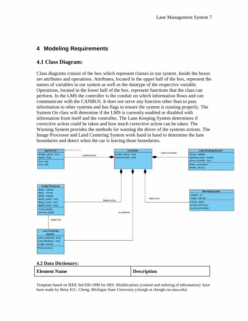
4.1 Class Diagram:
Class diagrams consist of the box which represent classes in our system. Inside the boxes
are attributes and operations. Attributes, located in the upper half of the box, represent the
names of variables in our system as well as the datatype of the respective variable.
Operations, located in the lower half of the box, represent functions that the class can
perform. In the LMS the controller is the conduit on which information flows and can
communicate with the CANBUS. It does not serve any function other than to pass
information to other systems and has flags to ensure the system is running properly. The
System On class will determine if the LMS is currently enabled or disabled with
information from itself and the controller. The Lane Keeping System determines if
corrective action could be taken and how much corrective action can be taken. The
Warning System provides the methods for warning the driver of the systems actions. The
Image Processor and Land Centering System work hand in hand to determine the lane
boundaries and detect when the car is leaving those boundaries.
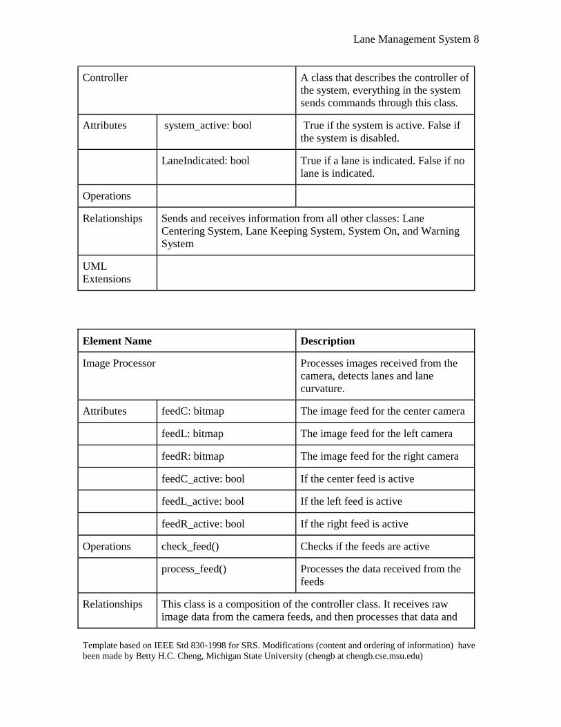
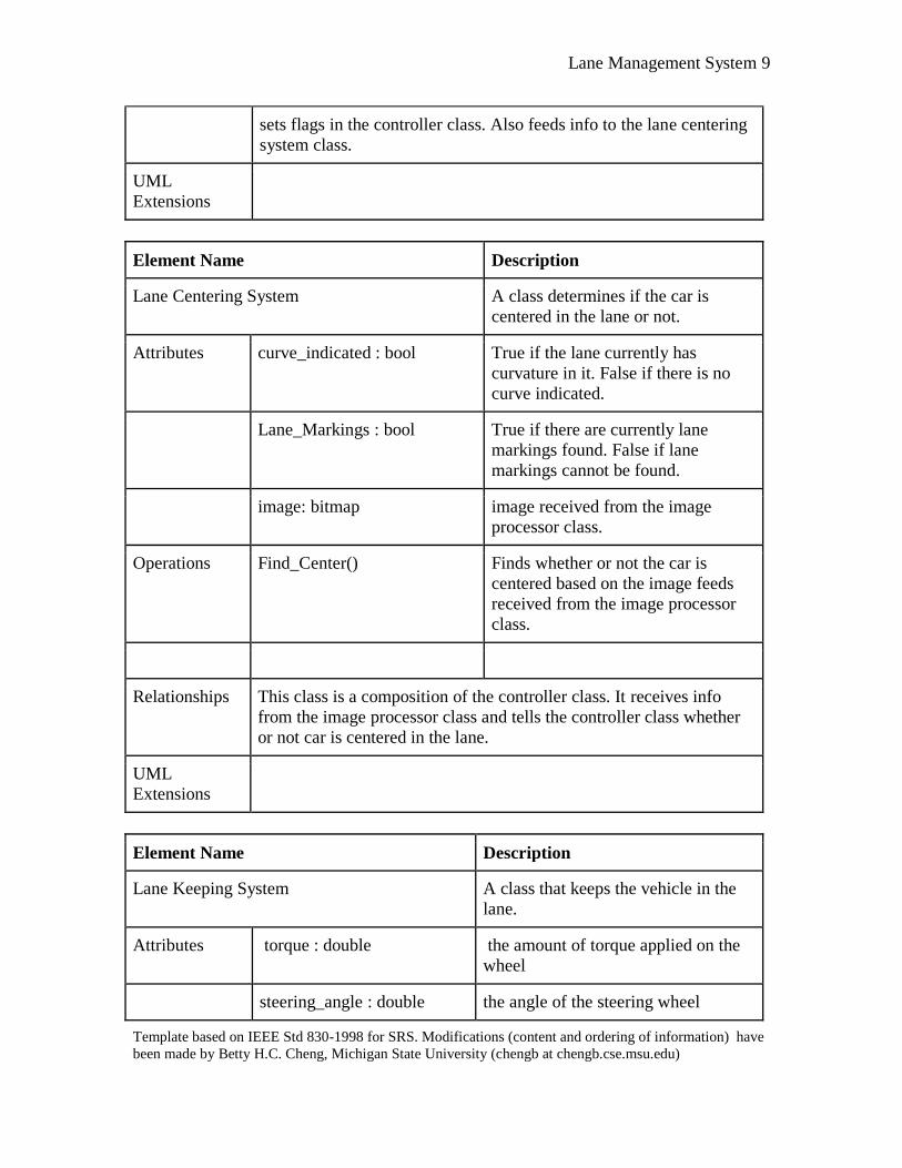
4.2 Data Dictionary:
Element Name Description
Lane Management System 8
Template based on IEEE Std 830-1998 for SRS. Modifications (content and ordering of information) have
been made by Betty H.C. Cheng, Michigan State University (chengb at chengb.cse.msu.edu)
Controller A class that describes the controller of
the system, everything in the system
sends commands through this class.
Attributes system_active: bool True if the system is active. False if
the system is disabled.
LaneIndicated: bool True if a lane is indicated. False if no
lane is indicated.
Operations
Relationships Sends and receives information from all other classes: Lane
Centering System, Lane Keeping System, System On, and Warning
System
UML
Extensions
Element Name Description
Image Processor Processes images received from the
camera, detects lanes and lane
curvature.
Attributes feedC: bitmap The image feed for the center camera
feedL: bitmap The image feed for the left camera
feedR: bitmap The image feed for the right camera
feedC_active: bool If the center feed is active
feedL_active: bool If the left feed is active
feedR_active: bool If the right feed is active
Operations check_feed() Checks if the feeds are active
process_feed() Processes the data received from the
feeds
Relationships This class is a composition of the controller class. It receives raw
image data from the camera feeds, and then processes that data and
Lane Management System 9
Template based on IEEE Std 830-1998 for SRS. Modifications (content and ordering of information) have
been made by Betty H.C. Cheng, Michigan State University (chengb at chengb.cse.msu.edu)
sets flags in the controller class. Also feeds info to the lane centering
system class.
UML
Extensions
Element Name Description
Lane Centering System A class determines if the car is
centered in the lane or not.
Attributes curve_indicated : bool True if the lane currently has
curvature in it. False if there is no
curve indicated.
Lane_Markings : bool True if there are currently lane
markings found. False if lane
markings cannot be found.
image: bitmap image received from the image
processor class.
Operations Find_Center() Finds whether or not the car is
centered based on the image feeds
received from the image processor
class.
Relationships This class is a composition of the controller class. It receives info
from the image processor class and tells the controller class whether
or not car is centered in the lane.
UML
Extensions
Element Name Description
Lane Keeping System A class that keeps the vehicle in the
lane.
Attributes torque : double the amount of torque applied on the
wheel
steering_angle : double the angle of the steering wheel
Lane Management System 10
Template based on IEEE Std 830-1998 for SRS. Modifications (content and ordering of information) have
been made by Betty H.C. Cheng, Michigan State University (chengb at chengb.cse.msu.edu)
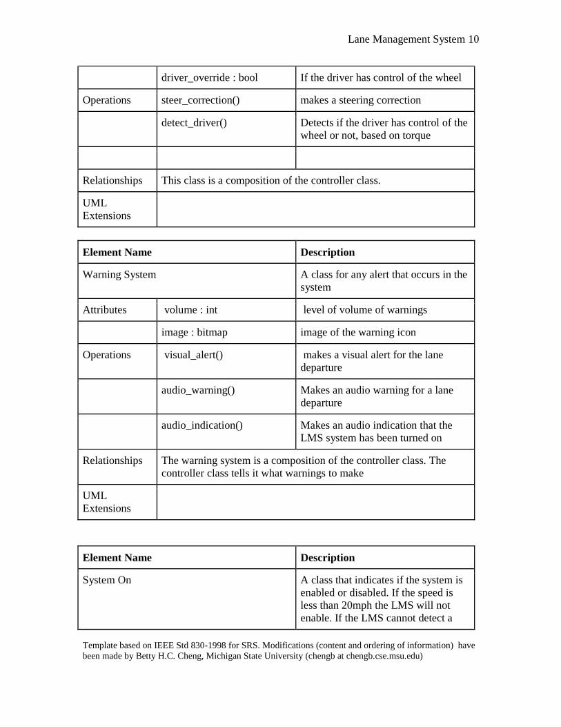
driver_override : bool If the driver has control of the wheel
Operations steer_correction() makes a steering correction
detect_driver() Detects if the driver has control of the
wheel or not, based on torque
Relationships This class is a composition of the controller class.
UML
Extensions
Element Name Description
Warning System A class for any alert that occurs in the
system
Attributes volume : int level of volume of warnings
image : bitmap image of the warning icon
Operations visual_alert() makes a visual alert for the lane
departure
audio_warning() Makes an audio warning for a lane
departure
audio_indication() Makes an audio indication that the
LMS system has been turned on
Relationships The warning system is a composition of the controller class. The
controller class tells it what warnings to make
UML
Extensions
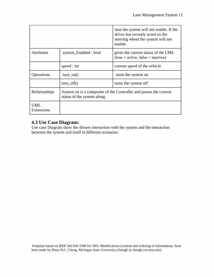
Element Name Description
System On A class that indicates if the system is
enabled or disabled. If the speed is
less than 20mph the LMS will not
enable. If the LMS cannot detect a
Lane Management System 11
Template based on IEEE Std 830-1998 for SRS. Modifications (content and ordering of information) have
been made by Betty H.C. Cheng, Michigan State University (chengb at chengb.cse.msu.edu)
lane the system will not enable. If the
driver has recently acted on the
steering wheel the system will not
enable.
Attributes system_Enabled : bool gives the current status of the LMS
(true = active, false = inactive)
speed : int current speed of the vehicle
Operations turn_on() turns the system on
turn_off() turns the system off
Relationships System on is a composite of the Controller and passes the current
status of the system along.
UML
Extensions
4.3 Use Case Diagram: Use case Diagram show the drivers interaction with the system and the interaction
between the system and itself in different scenarios:

Lane Management System 12
Template based on IEEE Std 830-1998 for SRS. Modifications (content and ordering of information) have
been made by Betty H.C. Cheng, Michigan State University (chengb at chengb.cse.msu.edu)
Use Case: Lane Centering System
Actors: Driver
Description: The system is actively detecting and calculating the center of the lane
and the car's relationship to it. The Lane Centering System uses data
from both the Camera Sensing and Image Processing subsystems to
calculate the appropriate center of lane position.
Type: Primary
Includes: System Disabled
Extends: No Lane Markings, Lane Curvature exists, Intentional Lane Change,

Lane Management System 13
Template based on IEEE Std 830-1998 for SRS. Modifications (content and ordering of information) have
been made by Betty H.C. Cheng, Michigan State University (chengb at chengb.cse.msu.edu)
Unintentional Lane Change
Cross-Refs: 3, 8.1, 8.2
Use cases: No Lane Markings, Lane Curvature exists, Intentional Lane Change,
Unintentional Lane Change
Use Case: Lane Keeping System
Actors: Driver
Description: The system detects the car is drifting and after a warning is issued
makes a corrective action. The Lane Keeping system intervenes and
sends commands to steer and adjust the position of the vehicle
accordingly as a means of accident prevention.
Type: Primary
Includes: System Disabled, Steering Correction
Extends: Unintentional Lane Change
Cross-Refs: 2, 8.3, 8.4, 7
Use cases: Unintentional Lane Change, Steering Correction
Lane Management System 14
Template based on IEEE Std 830-1998 for SRS. Modifications (content and ordering of information) have
been made by Betty H.C. Cheng, Michigan State University (chengb at chengb.cse.msu.edu)
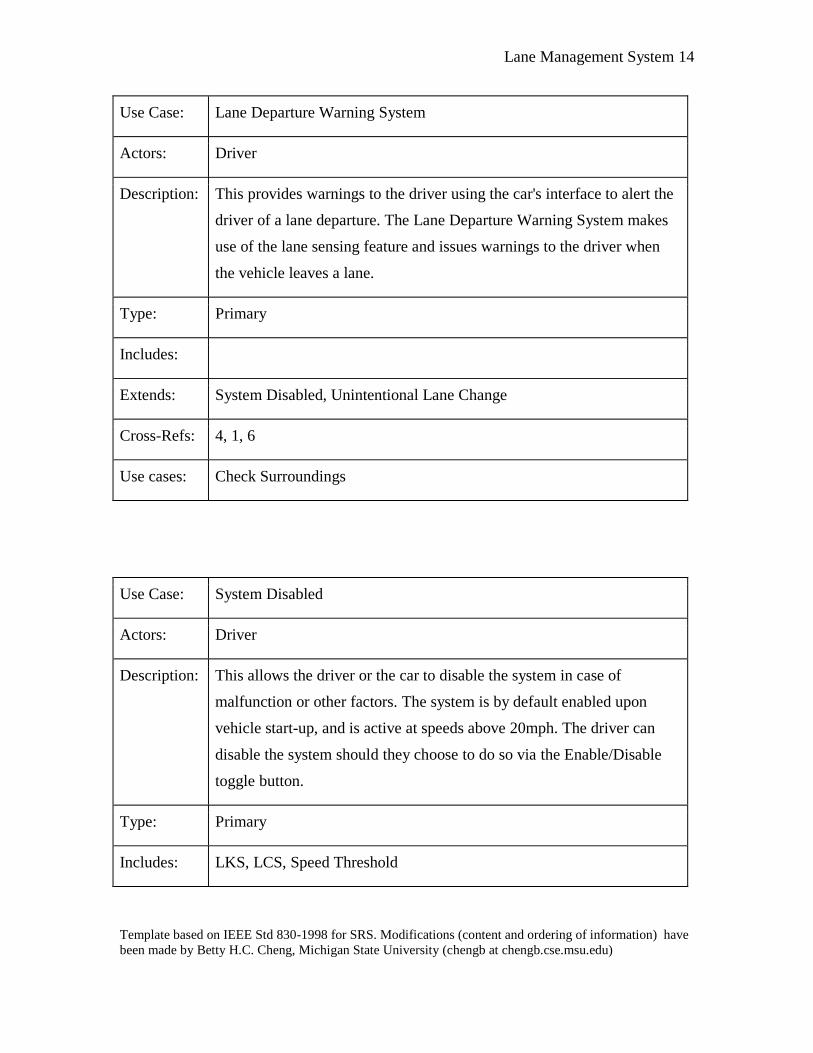
Use Case: Lane Departure Warning System
Actors: Driver
Description: This provides warnings to the driver using the car's interface to alert the
driver of a lane departure. The Lane Departure Warning System makes
use of the lane sensing feature and issues warnings to the driver when
the vehicle leaves a lane.
Type: Primary
Includes:
Extends: System Disabled, Unintentional Lane Change
Cross-Refs: 4, 1, 6
Use cases: Check Surroundings
Use Case: System Disabled
Actors: Driver
Description: This allows the driver or the car to disable the system in case of
malfunction or other factors. The system is by default enabled upon
vehicle start-up, and is active at speeds above 20mph. The driver can
disable the system should they choose to do so via the Enable/Disable
toggle button.
Type: Primary
Includes: LKS, LCS, Speed Threshold
Lane Management System 15
Template based on IEEE Std 830-1998 for SRS. Modifications (content and ordering of information) have
been made by Betty H.C. Cheng, Michigan State University (chengb at chengb.cse.msu.edu)
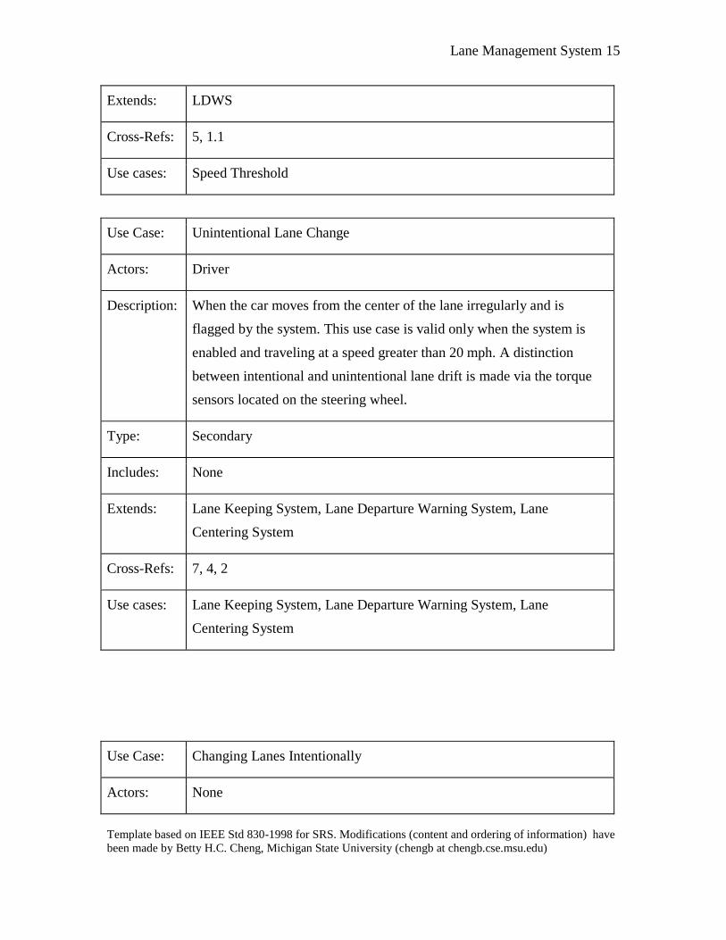
Extends: LDWS
Cross-Refs: 5, 1.1
Use cases: Speed Threshold
Use Case: Unintentional Lane Change
Actors: Driver
Description: When the car moves from the center of the lane irregularly and is
flagged by the system. This use case is valid only when the system is
enabled and traveling at a speed greater than 20 mph. A distinction
between intentional and unintentional lane drift is made via the torque
sensors located on the steering wheel.
Type: Secondary
Includes: None
Extends: Lane Keeping System, Lane Departure Warning System, Lane
Centering System
Cross-Refs: 7, 4, 2
Use cases: Lane Keeping System, Lane Departure Warning System, Lane
Centering System
Use Case: Changing Lanes Intentionally
Actors: None

Lane Management System 16
Template based on IEEE Std 830-1998 for SRS. Modifications (content and ordering of information) have
been made by Betty H.C. Cheng, Michigan State University (chengb at chengb.cse.msu.edu)
Description: The system automatically detects when the car is switching lanes
normally and takes no corrective action. The LMS distinguishes
between intentional and unintentional lane drift by the driver via the
torque sensor on the steering wheel of the vehicle.
Type: Secondary
Includes: None
Extends: Lane Centering System
Cross-Refs: 2, 5
Use cases: Lane Centering System
Use Case: Lane Curvature Exists
Actors: None
Description: The system detects when the road is curving and prepares to potentially
take corrective action. For this particular use case, the LMS makes use
of the Camera Sensing, Image Processing, and Vehicle State Estimation
subsystems to calculate and predict the curvature of the road in front of
the vehicle.
Type: Secondary
Includes: None
Extends: Lane Centering System
Cross-Refs: 8, 7
Use cases: Lane Keeping System, Lane Departure Warning System, Lane

Lane Management System 17
Template based on IEEE Std 830-1998 for SRS. Modifications (content and ordering of information) have
been made by Betty H.C. Cheng, Michigan State University (chengb at chengb.cse.msu.edu)
Centering System
Use Case: No Lane Markings
Actors: Driver, Car
Description: When there are no visible lane markings to assess the center of the lane
the system automatically enters a disabled state as a means of preventing
inaccurate data readings that could potentially lead to an accident or put
the driver in danger.
Type: Secondary
Includes: None
Extends: Lane Centering System
Cross-Refs: 8.3, 8.4, 7, 5
Use cases: Lane Centering System
Use Case: Speed Threshold
Actors: None
Description: The system should only be active at a certain speed or higher. The
system is by default enabled upon vehicle start-up, but is only active at
speeds greater than 20 mph.
Type: Secondary
Includes: System Disabled
Extends: None

Lane Management System 18
Template based on IEEE Std 830-1998 for SRS. Modifications (content and ordering of information) have
been made by Betty H.C. Cheng, Michigan State University (chengb at chengb.cse.msu.edu)
Cross-Refs: 5
Use cases: System Disabled
4.4 State Diagram: The following State diagram describes the movement of information and action
throughout the system while it is active:
4.5 Sequence Diagram:
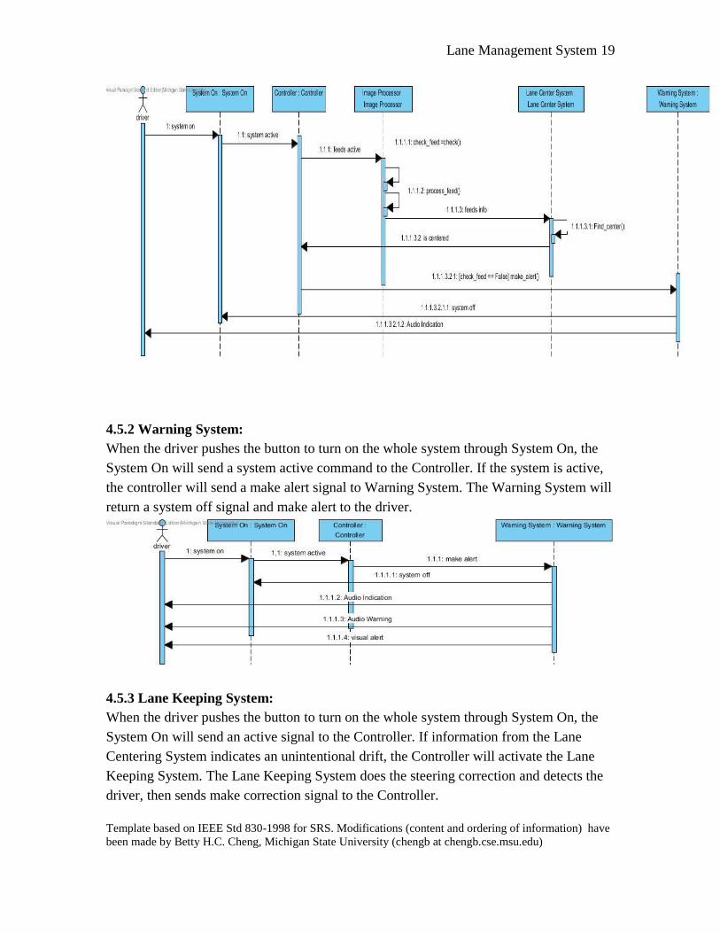
4.5.1 Image processor & Lane Centering System:
When the driver pushes the button to turn on the whole system through System On, and
the System On will send system active signal to the Controller. Then the Controller will
turn on the camera. The Image Processor will receive images from the cameras and
process them, then check if all of the camera feeds work well and sends all camera feeds
and flags to the Lane Centering System. The LCS will find the center of the lane and send
all information to the Controller. If check feed fails, the Controller will send a make alert
signal to the Warning System, which will then disable the system and make audio alert.
Lane Management System 19
Template based on IEEE Std 830-1998 for SRS. Modifications (content and ordering of information) have
been made by Betty H.C. Cheng, Michigan State University (chengb at chengb.cse.msu.edu)
4.5.2 Warning System:
When the driver pushes the button to turn on the whole system through System On, the
System On will send a system active command to the Controller. If the system is active,
the controller will send a make alert signal to Warning System. The Warning System will
return a system off signal and make alert to the driver.
4.5.3 Lane Keeping System:
When the driver pushes the button to turn on the whole system through System On, the
System On will send an active signal to the Controller. If information from the Lane
Centering System indicates an unintentional drift, the Controller will activate the Lane
Keeping System. The Lane Keeping System does the steering correction and detects the
driver, then sends make correction signal to the Controller.

Lane Management System 20
Template based on IEEE Std 830-1998 for SRS. Modifications (content and ordering of information) have
been made by Betty H.C. Cheng, Michigan State University (chengb at chengb.cse.msu.edu)
5 Prototype
The prototype shows the capability to enable and disable the system, the conditions by
which the visual warnings are flagged, and the settings which can be configured.
5.1 How to Run Prototype
The prototype is accessed through the internet. No internet connection would be required
in the final product. A web browser is required to view and interact with the prototype.
Additionally, it requires an internet connection to import jQuery, the Web Speech API
and for the user to access the prototype.
The jQuery library is the only dependency for this prototype. It also uses the Web Speech
API. It is written in HTML, CSS and jQuery. The prototype can be found at the following
location:
http://www.cse.msu.edu/~cse435/Projects/F2016/Groups/LANE1/web/prototype.html
5.2 Sample Scenarios
The user would like to observe the system behavior while the system is active and when a
driver unintentionally drifts into the left lane containing oncoming traffic. The user
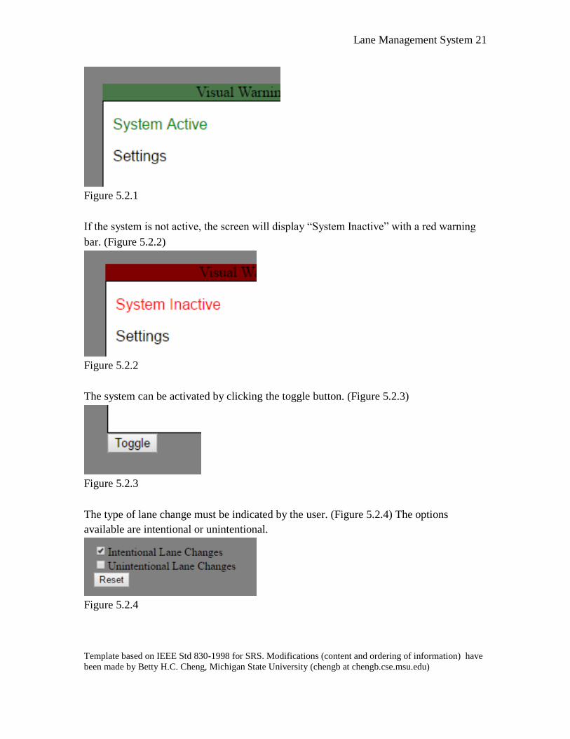
begins by verifying the status of the system on the screen and in the warning bar. Both
will be green while the system is currently active (Figure 5.2.1)
Lane Management System 21
Template based on IEEE Std 830-1998 for SRS. Modifications (content and ordering of information) have
been made by Betty H.C. Cheng, Michigan State University (chengb at chengb.cse.msu.edu)
Figure 5.2.1
If the system is not active, the screen will display “System Inactive” with a red warning
bar. (Figure 5.2.2)
Figure 5.2.2
The system can be activated by clicking the toggle button. (Figure 5.2.3)
Figure 5.2.3
The type of lane change must be indicated by the user. (Figure 5.2.4) The options
available are intentional or unintentional.
Figure 5.2.4

Lane Management System 22
Template based on IEEE Std 830-1998 for SRS. Modifications (content and ordering of information) have
been made by Betty H.C. Cheng, Michigan State University (chengb at chengb.cse.msu.edu)
The user may use the up and right or left arrows of the keyboard (↑, ←↑, or ↑→) to move the car forward or forward and to the left or right. In this case, since the user wants to observe the driver drifting into the left lane, they will simultaneously hold the up and left arrow keys.
The user can observe the vehicle moving into the left lane. (Figure 5.2.5) The warning
system will then be flagged and the audio and visual warning will be raised. The speaker
icon appears under the toggle button and the warning bar changes color to a bright red.
(Figure 5.2.6) An audio recording will also play the audio warning. (Figure 5.2.7)
Figure 5.2.5
Figure 5.2.6
Figure 5.2.7
Lane Management System 23
Template based on IEEE Std 830-1998 for SRS. Modifications (content and ordering of information) have
been made by Betty H.C. Cheng, Michigan State University (chengb at chengb.cse.msu.edu)
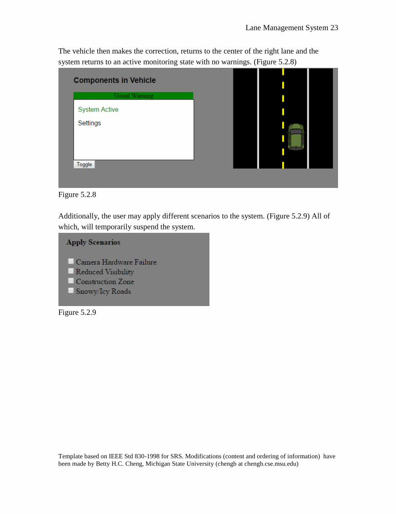
The vehicle then makes the correction, returns to the center of the right lane and the
system returns to an active monitoring state with no warnings. (Figure 5.2.8)
Figure 5.2.8
Additionally, the user may apply different scenarios to the system. (Figure 5.2.9) All of
which, will temporarily suspend the system.
Figure 5.2.9

Lane Management System 24
Template based on IEEE Std 830-1998 for SRS. Modifications (content and ordering of information) have
been made by Betty H.C. Cheng, Michigan State University (chengb at chengb.cse.msu.edu)
6 References
[1] Dr. Betty H.C. Cheng and Dr. S Ramesh, “GM-Lane_Management_System-v2”,
General Motors
[2] Dr. S Ramesh, “Client Question & Answer”, General Motors and Michigan State
University, October 2016
[3] Adam Prium, Matt Chebowski, Quining Ren, Curtis Notarantonio, Jacob Heisey,
“Lane 1 Website” http://www.cse.msu.edu/~cse435/Projects/F2016/Groups/LANE1/web/
[4] Lane Keeping Assist. (n.d.). Retrieved October 12, 2016, from
http://www.toyota-
global.com/innovation/safety_technology/safety_technology/technology_file/active/lka
.html
[5] Lane Departure Alert (LDA). (n.d.). Retrieved October 12, 2016, from http://www.toyota-global.com/innovation/safety_technology/safety_technology/technology_file/active/lda.html
7 Point of Contact
For further information regarding this document and project, please contact Prof. Betty
H.C. Cheng at Michigan State University (chengb at cse.msu.edu). All materials in this
document have been sanitized for proprietary data. The students and the instructor
gratefully acknowledge the participation of our industrial collaborators.


