Download - Solar Power Systems

Solar Power Systems
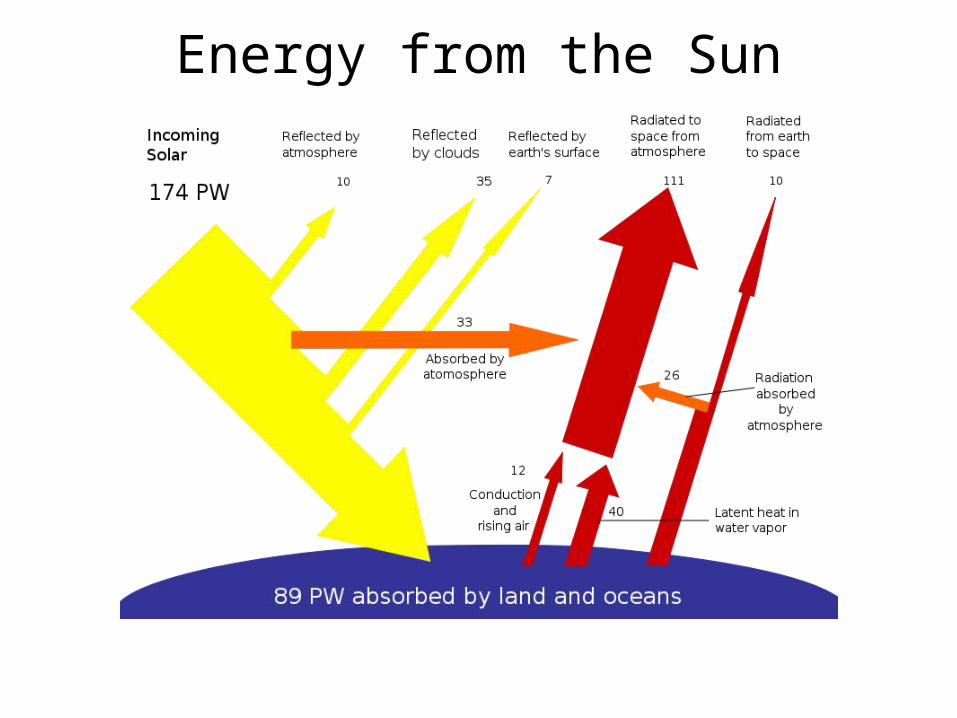
Energy from the Sun

Solar Energy

Practical Uses of Solar Energy

Solar Water Heaters

Photovoltaic Development
Edmund Becquerel 1839
William Grylls Adams 1876
Gerald Pearson, Daryl Chapin, and Calvin Fuller 1953
Russell Ohl 1940

Space Race Saves PV
Vanguard I Satellite 1958 One Watt
Telstar Satellite 1962 14 Watts

From Novelty to Real World Applications
Buoys and Lighthouses
Offshore Oil PlatformsRR Crossings Rex, GA 1974

P-N Junction

Photovoltaic cell

Electrical Properties of a Solar Cell
Isc
– V +
I
)1( BVeA
External circuit (e.g., battery,
lights)
)1( BVeA
0
5
0.0 0.6Diode Volts
Dio
de A
mps
Diode current
)1( BVeA
)1( BVsc eAII
V
I
Isc
Voc
Im
Vm
, where A, B, and especially Isc vary with solar insolation
0
0
Increasing solar insolation
mm IVP max
Maximum power point
)1( BVsc eAII
I – V Curves

Terms• Solar Irradiance (density), average 1 kW per square
meter at noon on a clear day at sea level• Solar Insolation: hours per day that solar panel delivers
rated voltage, varies seasonally• STC: standard test conditions, 25° C, 1 kW per square
meter irradiance & AM 1.5• AM: Air Mass, density & clarity of air sunlight passes
through to reach the modules
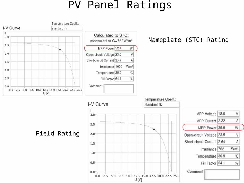
PV Panel Ratings
Nameplate (STC) Rating
Field Rating

The PV Cell & Panel Families
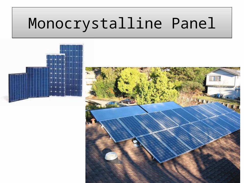
Monocrystalline Panel
Thin Film Panel
Polycrystalline Panel

PV Cells and Panel Assembly
Monocrystalline PanelMonocrystalline Panel

Polycrystalline PanelPolycrystalline Panel

Thin Film Panel

PV Basics PV Basics
PV CELL OVERVIEW
SINGLE CRYSTALLINEPOLYCRYSTALLINE
CELLSTRING RIBBON
AMORPHOUS OR THIN FILM
Typically dark blue in color
Typically dark blue in color
Typically dark blue in color
Typically black in color
Efficiency averages 10% to 12%
Efficiency averages 9% to 11%
Efficiency averages 10% to 11%
Efficiency averages 6% to 9%
Degradation averaging 0.25% to 0.5% per year
Degradation averaging 0.25% to 0.5% per year
Degradation averaging 0.25% to 0.5% per year
Degradation averaging 0.25% to 0.5% per year
Vendors typically guarantee power 90% for 10 years , 80% for
25 years
Vendors typically guarantee power 90% for 10 years, 80% for
25 years
Vendors typically guarantee power 90% for 10 years , 80% for
25 years
Vendors typically guarantee power 90% for 10 years, 80% for
25 years
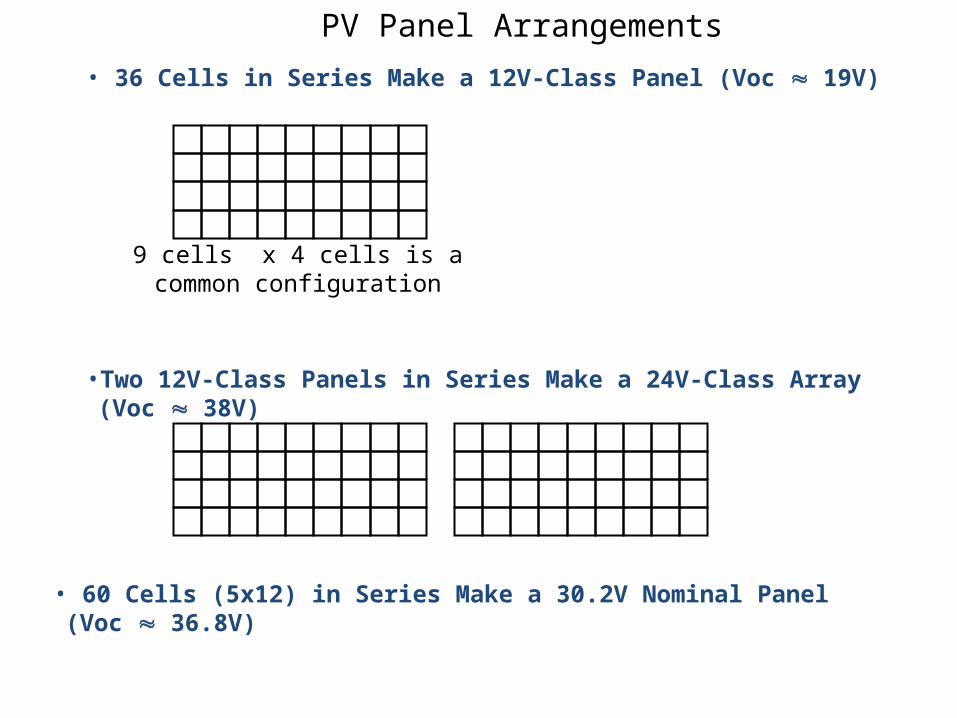
• 36 Cells in Series Make a 12V-Class Panel (Voc 19V)
•Two 12V-Class Panels in Series Make a 24V-Class Array (Voc 38V)
9 cells x 4 cells is acommon configuration
• 60 Cells (5x12) in Series Make a 30.2V Nominal Panel (Voc 36.8V)
PV Panel Arrangements

PV Systems
Utility Intertie
Stand alone direct connected

Stand alone PV System

Typical Grid Tie without BatteryTypical Grid Tie without Battery
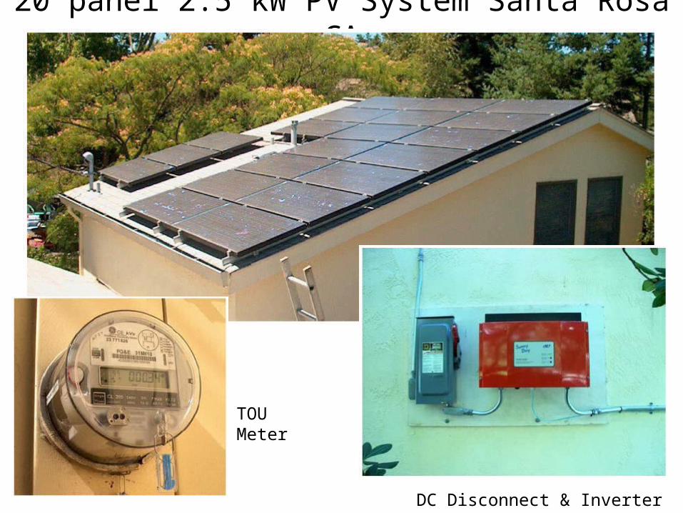
20 panel 2.5 kW PV System Santa Rosa CA
DC Disconnect & Inverter
TOUMeter

Metering Data
TOU rate 31¢/kwh Noon to 6PM (peak solar production); non-peak rate 11¢/kwh

Quantifying the Resource

Location, Location, Location

PV Mounting SystemsPV Mounting Systems• Does your site location need to meet special building
requirements? • What is the maximum wind speed that it must be designed for?• What is the maximum snow loading that it must be designed for?• What structures best use the soil type in your area?• Can you drive piers directly into the ground or do you need
concrete? This will require a geotechnical study of the site and can result in a significant cost savings.
• Can you use a ballasted system?• What height does your system need to be to avoid being covered
by snow, or vegetation?• If you decide to track, what are the lowest temperatures that
system will see?

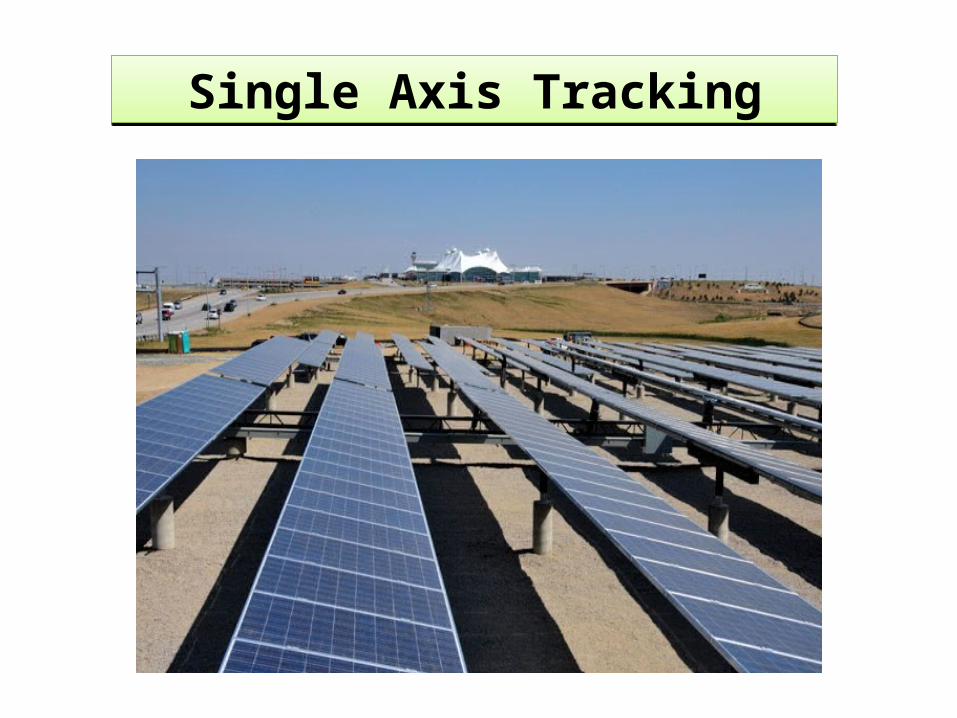
Single Axis TrackingSingle Axis Tracking
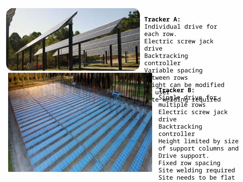
Tracker A:Individual drive for each row.Electric screw jack driveBacktracking controllerVariable spacing between rowsHeight can be modified by userSite welding required
Tracker B:Single drive for multiple rowsElectric screw jack driveBacktracking controllerHeight limited by size of support columns and Drive support.Fixed row spacingSite welding requiredSite needs to be flat and level
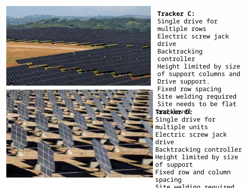
Tracker C:Single drive for multiple rowsElectric screw jack driveBacktracking controllerHeight limited by size of support columns and Drive support.Fixed row spacingSite welding requiredSite needs to be flat and level
Tracker D:Single drive for multiple unitsElectric screw jack driveBacktracking controllerHeight limited by size of support Fixed row and column spacingSite welding requiredSite needs to be flat and level

A 2 AXIS A 2 AXIS
B 2 AXISB 2 AXIS
C 2 axisC 2 axis

Your roof top is valuable real estate, without the permitting problems associated with brownfield installations
Rack PV roof mounting systemAccepts most standard PVRoof loading dependent on tilt angleFrom 2 lbs/ft 2 with penetrations to a ballasted system with no penetrations.

Examples of Roof Top InstallsExamples of Roof Top Installs
Phizer = KW 337 Tilt Angle 5 deg. Number of Modules 1,372
California Residence2.5 kW, 20 panels

DC Circuit CombinerDC Circuit Combiner
PV ARRAYPV ARRAY14 modules in series forms one string 10 strings in parallel form an array
Combiner box
Inverter Input

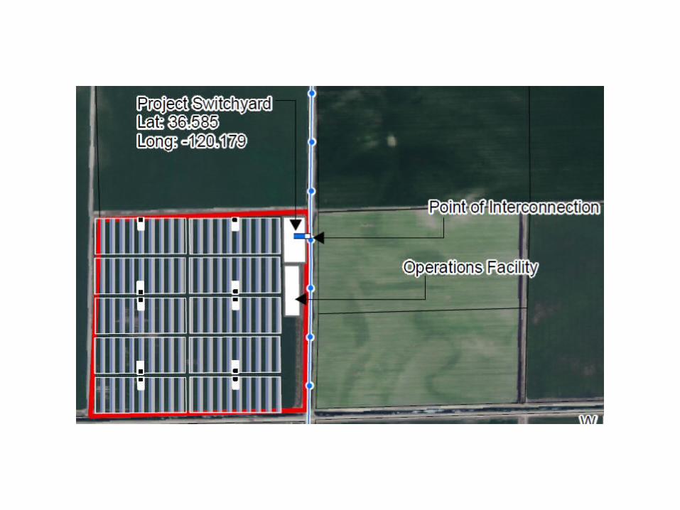
1 MW PV Array1 MW PV Array

Sub Array Combiner Box with String Monitoring

Field Combiner Boxes

Grid Tie Inverter
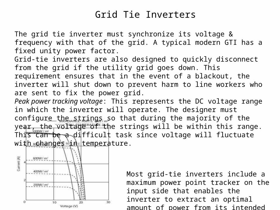
The grid tie inverter must synchronize its voltage & frequency with that of the grid. A typical modern GTI has a fixed unity power factor. Grid-tie inverters are also designed to quickly disconnect from the grid if the utility grid goes down. This requirement ensures that in the event of a blackout, the inverter will shut down to prevent harm to line workers who are sent to fix the power grid.Peak power tracking voltage: This represents the DC voltage range in which the inverter will operate. The designer must configure the strings so that during the majority of the year, the voltage of the strings will be within this range. This can be a difficult task since voltage will fluctuate with changes in temperature.
Most grid-tie inverters include a maximum power point tracker on the input side that enables the inverter to extract an optimal amount of power from its intended power source.
Grid Tie Inverters
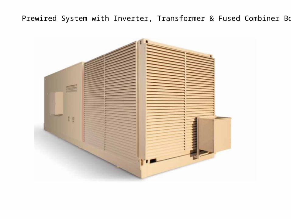
Prewired System with Inverter, Transformer & Fused Combiner Boxes


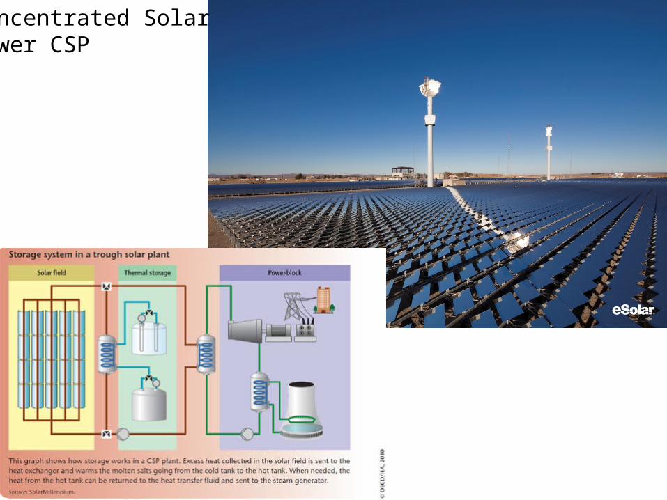
Concentrated Solar Power CSP

Rick Downer – POWER Engineers Inc.IEEE IAS April 18, 2011


