
Sun Microsystems, Inc.901 San Antonio Road
Palo Alto, CA 94303U.S.A. 650-960-1300
Part No. 805-3524-10March 1998, Revision A
Solaris Handbook for SMCCFrame Buffers
Solaris ™ 2.6 Hardware: 3/98Contains important information on configurationoptions for the various frame buffers.
Send comments about this document to: [email protected]


Copyright 1998 Sun Microsystems, Inc., 901 San Antonio Road, Palo Alto, California 94303 U.S.A. All rights reserved.
This product or document is protected by copyright and distributed under licenses restricting its use, copying, distribution, and decompilation.
No part of this product or document may be reproduced in any form by any means without prior written authorization of Sun and its licensors,
if any. Third-party software, including font technology, is copyrighted and licensed from Sun suppliers.
Parts of the product may be derived from Berkeley BSD systems, licensed from the University of California. UNIX is a registered trademark in
the U.S. and other countries, exclusively licensed through X/Open Company, Ltd.
Sun, Sun Microsystems, the Sun logo, SunSoft, SunDocs, SunExpress, Solaris, OpenBoot, Ultra, VIS, XIL, XGL, X11/NeWS, Direct Xlib, S24,
TurboGX, TurboGXplus, and TurboZX are trademarks, registered trademarks, or service marks of Sun Microsystems, Inc. in the U.S. and other
countries. All SPARC trademarks are used under license and are trademarks or registered trademarks of SPARC International, Inc. in the U.S.
and other countries. Products bearing SPARC trademarks are based upon an architecture developed by Sun Microsystems, Inc.
The OPEN LOOK and Sun™ Graphical User Interface was developed by Sun Microsystems, Inc. for its users and licensees. Sun acknowledges
the pioneering efforts of Xerox in researching and developing the concept of visual or graphical user interfaces for the computer industry. Sun
holds a non-exclusive license from Xerox to the Xerox Graphical User Interface, which license also covers Sun’s licensees who implement OPEN
LOOK GUIs and otherwise comply with Sun’s written license agreements.
RESTRICTED RIGHTS: Use, duplication, or disclosure by the U.S. Government is subject to restrictions of FAR 52.227-14(g)(2)(6/87) and
FAR 52.227-19(6/87), or DFAR 252.227-7015(b)(6/95) and DFAR 227.7202-3(a).
DOCUMENTATION IS PROVIDED “AS IS” AND ALL EXPRESS OR IMPLIED CONDITIONS, REPRESENTATIONS AND WARRANTIES,
INCLUDING ANY IMPLIED WARRANTY OF MERCHANTABILITY, FITNESS FOR A PARTICULAR PURPOSE OR NON-INFRINGEMENT,
ARE DISCLAIMED, EXCEPT TO THE EXTENT THAT SUCH DISCLAIMERS ARE HELD TO BE LEGALLY INVALID.
Please
Recycle

Copyright 1998 Sun Microsystems, Inc., 901 San Antonio Road, Palo Alto, Californie 94303 Etats-Unis. Tous droits réservés.
Ce produit ou document est protégé par un copyright et distribué avec des licences qui en restreignent l’utilisation, la copie, la distribution, et la
décompilation. Aucune partie de ce produit ou document ne peut être reproduite sous aucune forme, par quelque moyen que ce soit, sans
l’autorisation préalable et écrite de Sun et de ses bailleurs de licence, s’il y en a. Le logiciel détenu par des tiers, et qui comprend la technologie
relative aux polices de caractères, est protégé par un copyright et licencié par des fournisseurs de Sun.
Des parties de ce produit pourront être dérivées des systèmes Berkeley BSD licenciés par l’Université de Californie. UNIX est une marque
déposée aux Etats-Unis et dans d’autres pays et licenciée exclusivement par X/Open Company, Ltd.
Sun, Sun Microsystems, le logo Sun, SunSoft, SunDocs, SunExpress, Solaris, OpenBoot, Ultra, VIS, XIL, XGL, X11/NeWS, Direct Xlib, S24,
TurboGX, TurboGXplus, and TurboZX sont des marques de fabrique ou des marques déposées, ou marques de service, de Sun Microsystems,
Inc. aux Etats-Unis et dans d’autres pays. Toutes les marques SPARC sont utilisées sous licence et sont des marques de fabrique ou des marques
déposées de SPARC International, Inc. aux Etats-Unis et dans d’autres pays. Les produits portant les marques SPARC sont basés sur une
architecture développée par Sun Microsystems, Inc.
L’interface d’utilisation graphique OPEN LOOK et Sun™ a été développée par Sun Microsystems, Inc. pour ses utilisateurs et licenciés. Sun
reconnaît les efforts de pionniers de Xerox pour la recherche et le développement du concept des interfaces d’utilisation visuelle ou graphique
pour l’industrie de l’informatique. Sun détient une licence non exclusive de Xerox sur l’interface d’utilisation graphique Xerox, cette licence
couvrant également les licenciés de Sun qui mettent en place l’interface d’utilisation graphique OPEN LOOK et qui en outre se conforment aux
licences écrites de Sun.
CETTE PUBLICATION EST FOURNIE "EN L’ETAT" ET AUCUNE GARANTIE, EXPRESSE OU IMPLICITE, N’EST ACCORDEE, Y COMPRIS
DES GARANTIES CONCERNANT LA VALEUR MARCHANDE, L’APTITUDE DE LA PUBLICATION A REPONDRE A UNE UTILISATION
PARTICULIERE, OU LE FAIT QU’ELLE NE SOIT PAS CONTREFAISANTE DE PRODUIT DE TIERS. CE DENI DE GARANTIE NE
S’APPLIQUERAIT PAS, DANS LA MESURE OU IL SERAIT TENU JURIDIQUEMENT NUL ET NON AVENU.

Contents
Preface xiii
1. TurboGXplus Frame Buffer 1
TurboGXplus-supported Monitors 1
Default Screen Resolutions 3
Programming the Screen Resolution 3
Configuring Monitors Using a UNIX Script 6
Configuring Monitors Using the PROM Method 6
Setting Up a Single Monitor Using the PROM Method 7
Setting Up a Single Monitor Using a UNIX Script 8
Setting Up Multiple Monitors Using a UNIX Script 8
2. S24 Frame Buffer 11
S24 Application Compatibility 11
S24 Frame Buffer Screen Resolutions 12
Default Screen Resolutions 13
Changing the Screen Resolution 13
3. ZX and TurboZX Graphics Accelerator 15
ZX-supported Monitors 16
Default Screen Resolutions 17
v

Supported Screen Resolutions 17
Changing the Screen Resolution 18
▼ To Change the Screen Resolution Temporarily 18
Modifying the leoconfig Initialization File 19
▼ To Modify the leoconfig File 19
ZX Graphics Accelerator Restrictions 21
Using a Non-Sun Monitor as Console 21
Restrictions to Changing the Default Screen Resolution 22
Stereo Connector 22
Stereo Cable on the Ultra 1 System 23
4. SX Frame Buffer 25
SX-supported Monitors 26
Default Screen Resolutions 27
Changing the Screen Resolution 28
Changing the Pixel Depth 29
XIL Acceleration on the SX Frame Buffer 30
5. Creator Graphics Accelerator 31
Default Screen Resolutions 32
Supported Screen Resolutions 33
Changing Screen Resolutions (-res ) 34
▼ To Find Resolutions Supported By Creator and the Connected Monitor 34
▼ To Change Screen Resolutions Temporarily 34
▼ To Change the Screen Resolution to Stereo 35
Changing Screen Visuals List 35
Changing the Visual List Order (-linearorder , -overlayorder ) 35
Changing the Default Visual (-deflinear , -defoverlay ) 36
Changing OpenGL Visual Support (-expvis ) 37
vi Solaris Handbook for SMCC Frame Buffers • March 1998
Changing SERVER_OVERLAY_VISUALS Support (-sov ) 38
Creator Series 3 Options 38
Setting Gamma Correction (-g , -gfile ) 38
Choosing Extended Overlay (-extovl ) 39
Times-Roman on Screen Visual List by Various ffbconfig Visual Flags 40
Effect on the Default Visual and the Visual Group Ordering 40
Effect on the Number of Visual Instances Within Selected Groups 41
Addition of the SERVER_OVERLAY_VISUALS Property and the
Transparent SOV Visuals in the 8-bit Overlay Group 42
Stereo Connector 44
Creator Series 1 Stereo Connector 44
Creator Series 2 Stereo Connector 45
Stereo Signal 46
6. The Creator Window System 47
Creator Visuals 48
List of Visuals 48
Overlay and Underlay Structure 50
Comparison with the SX Accelerator 50
Comparing Creator with the ZX Accelerator 52
Hardware Color LUT Usage 53
Reducing Colormap Flashing 53
Notes to End Users 54
Notes to Programmers 54
Hardware Window IDs 55
Cursor Management 56
Hardware Double Buffering 57
Device Configuration 57
Performance Notes 58
Contents vii

Direct Xlib 58
The X11perf Benchmark 59
No Creator Pixel Copy Hardware 59
Background None Window Transient Color Effects 59
7. XIL Acceleration on the Creator Graphics Accelerator 61
XIL Data Types 61
Accelerated Functions 62
Double Buffer Support 65
8. PGX Graphics Accelerator 69
Supported Screen Resolutions 70
Changing the Screen Resolution Temporarily 70
Printing the PGX Hardware Configuration 72
For More Information 73
PEX Library Bug Workaround 73
9. Multiple Monitors on a System 75
Multiple Monitor Configuration 75
Device File Names 76
Checking the Available Frame Buffers 77
Starting OpenWindows from the Console 78
Running OpenWindows on Multiple Monitors 78
Changing the Polling Order 80
SBus Addresses 80
Polling Order 80
Changing the sbus-probe-list 81
Index 83
viii Solaris Handbook for SMCC Frame Buffers • March 1998

Figures
FIGURE 3-1 ZX Stereo Connector Signal 23
FIGURE 3-2 ZX Stereo Signal 23
FIGURE 3-3 Ferrite Core on Stereo Cable (Ultra 1 Systems Only) 24
FIGURE 5-1 Creator Series 1 Stereo Connector 44
FIGURE 5-2 Creator Series 2 Stereo Connector 45
FIGURE 5-3 Creator Stereo Signal 46
FIGURE 6-1 The 11 Creator Accelerator Visuals 49
FIGURE 7-1 Creator Depth-cueing 64
FIGURE 9-1 SBus Probe List Explanation 81
ix

x Solaris Handbook for SMCC Frame Buffers • March 1998

Tables
TABLE 1-1 Monitors Supported by TurboGXplus 2
TABLE 1-2 TurboGXplus Monitor Sense Codes 3
TABLE 1-3 Video Setup Specifications 4
TABLE 1-4 TurboGXplus Resolution Codes 7
TABLE 2-1 S24 Frame Buffer Monitor Sense Codes 13
TABLE 3-1 Monitors Supported by ZX 16
TABLE 3-2 ZX Frame Buffer Monitor Sense Codes 17
TABLE 3-3 ZX Supported Screen Resolutions 17
TABLE 3-4 Monitor Types 18
TABLE 4-1 Monitors Supported by SX 26
TABLE 4-2 SX Frame Buffer Monitor Sense Codes 27
TABLE 4-3 SX -supported Screen Resolutions 28
TABLE 4-4 SX Frame Buffer Visuals and Double-buffering 29
TABLE 5-1 Creator Graphics Accelerator Monitor Sense Codes 32
TABLE 5-2 Creator-supported Screen Resolutions 33
TABLE 5-3 The Default Settings of the ffbconfig Visual Flags 35
TABLE 5-4 Creator Series 2 Stereo Connector Signals 45
TABLE 7-1 Accelerated XIL Functions 62
TABLE 8-1 PGX-supported Screen Resolutions 70
xi

TABLE 8-2 PGX-screen Resolution Formats 71
xii Solaris Handbook for SMCC Frame Buffers • March 1998

Preface
Solaris Handbook for SMCC Frame Buffers contains important information on
configuration options for the various frame buffers. The frame buffer devices
described in this document are:
■ TurboGXplus™ Frame Buffer
■ S24™ Frame Buffer
■ ZX and TurboZX™ Graphics Accelerator
■ SX Frame Buffer
■ Creator and Creator 3D Graphics Accelerators
■ PGX Graphics Accelerator
This book is intended for anyone who needs to configure one of the described frame
buffers or graphics accelerators to meet specific video or graphics requirements.
How This Book Is Organized
This book consists of the following chapters:
Chapter 1, “TurboGXplus Frame Buffer,” describes how to configure a system using
a TurboGXplus card to suit different screen resolutions and to support multiple
monitors.
Chapter 2, “S24 Frame Buffer,” describes the S24 Frame Buffer hardware options.
Chapter 3, “ZX and TurboZX Graphics Accelerator,” describes how to change ZX
and TurboZX Graphics Accelerator screen resolution to work properly with different
monitors.
Chapter 4, “SX Frame Buffer,” describes how to change the display resolution on
the SX Frame Buffer (cgfourteen).
Preface xiii

Chapter 5, “Creator Graphics Accelerator,” describes a UNIX® shell-based utility
that can be used to select configuration options for the Creator or Creator 3D
Graphics Accelerator, the attached monitor, and the associated X11 screen.
Chapter 6, “The Creator Window System,” describes how the Solaris X11 window
system works on the Creator and Creator 3D Graphics Accelerators.
Chapter 7, “XIL Acceleration on the Creator Graphics Accelerator,” describes the
XIL functions that are specific to the Creator and Creator 3D Graphics Accelerators.
Chapter 8, “PGX Graphics Accelerator,” describes the use of the m64config utility
to change the display resolution on the PGX Graphics Accelerator.
Chapter 9, “Multiple Monitors on a System,” describes how to use multiple
monitors on a SPARCstation system.
Typographic Conventions
The following table describes the typographic changes used in this book.
TABLE P-1 Typographic Conventions
Typeface orSymbol Meaning Example
AaBbCc123 The names of commands, files,
and directories; on-screen
computer output
Edit your .login file.
Use ls -a to list all files.
machine_name% You have mail.
AaBbCc123 What you type, contrasted with
on-screen computer output
machine_name% suPassword:
AaBbCc123 Command-line placeholder:
replace with a real name or
value
To delete a file, type rm filename.
AaBbCc123 Book titles, new words or
terms, or words to be
emphasized
Read Chapter 6 in the User’s Guide.
These are called class options.
You must be root to do this.
xiv Solaris Handbook for SMCC Frame Buffers • March 1998
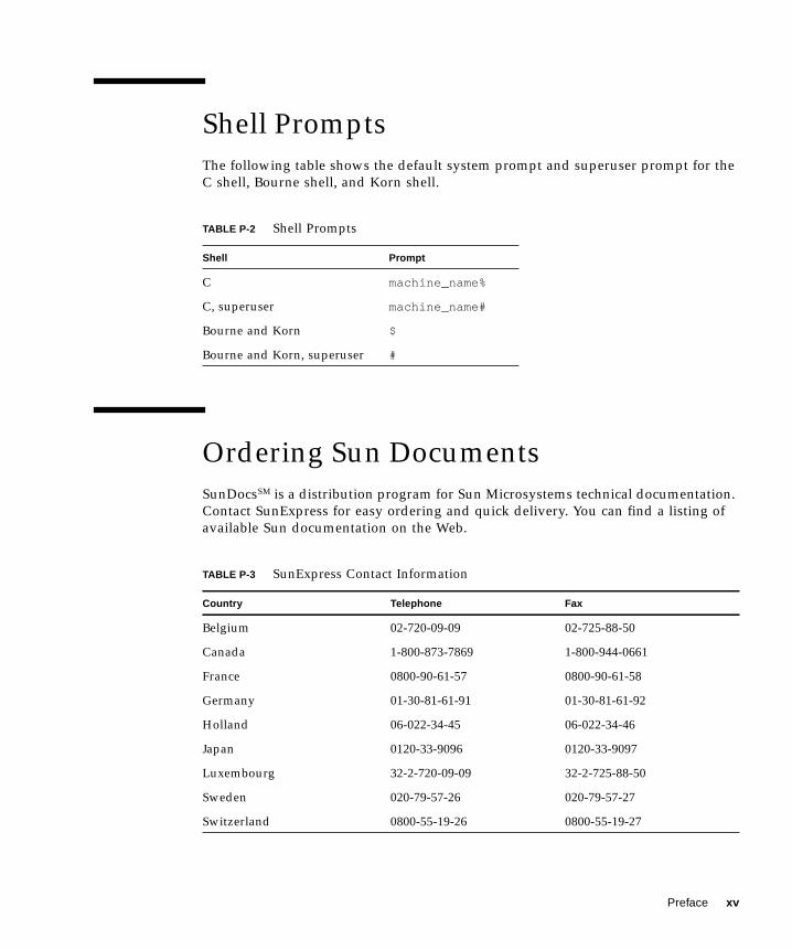
Shell Prompts
The following table shows the default system prompt and superuser prompt for the
C shell, Bourne shell, and Korn shell.
Ordering Sun Documents
SunDocsSM is a distribution program for Sun Microsystems technical documentation.
Contact SunExpress for easy ordering and quick delivery. You can find a listing of
available Sun documentation on the Web.
TABLE P-2 Shell Prompts
Shell Prompt
C machine_name%
C, superuser machine_name#
Bourne and Korn $
Bourne and Korn, superuser #
TABLE P-3 SunExpress Contact Information
Country Telephone Fax
Belgium 02-720-09-09 02-725-88-50
Canada 1-800-873-7869 1-800-944-0661
France 0800-90-61-57 0800-90-61-58
Germany 01-30-81-61-91 01-30-81-61-92
Holland 06-022-34-45 06-022-34-46
Japan 0120-33-9096 0120-33-9097
Luxembourg 32-2-720-09-09 32-2-725-88-50
Sweden 020-79-57-26 020-79-57-27
Switzerland 0800-55-19-26 0800-55-19-27
Preface xv

Sun Documentation on the WebThe docs.sun.com web site enables you to access Sun technical documentation on
the Web. You can browse the docs.sun.com archive or search for a specific book
title or subject at:
http://docs.sun.com.
Sun Welcomes Your Comments
We are interested in improving our documentation and welcome your comments
and suggestions. You can email your comments to us at:
■ Email: [email protected]
■ Fax: SMCC Document Feedback
1-650-786-6443
Please include the part number of your document in the subject line of your email.
United Kingdom 0800-89-88-88 0800-89-88-87
United States 1-800-873-7869 1-800-944-0661
World Wide Web: http://www.sun.com/sunexpress/
TABLE P-3 SunExpress Contact Information (Continued)
xvi Solaris Handbook for SMCC Frame Buffers • March 1998

CHAPTER 1
TurboGXplus Frame Buffer
This chapter describes how you can configure your system using a TurboGXplus™
card to suit your specific video and graphics requirements. The information
describes how to set up your TurboGXplus to support different screen resolutions
and how to set up the system to support multiple monitors.
TurboGXplus-supported Monitors
TABLE 1-1 shows the list of monitors supported by the TurboGXplus card.
1

Note – The monitors listed in TABLE 1-1 are subject to change as Sun Microsystems
announces new monitors. Contact your local Sun representative for a listing of
supported monitors.
TABLE 1-1 Monitors Supported by TurboGXplus
Model Sun Part Number Type/Size/FCCMonitor IDSense Code Standard Resolution and Refresh Rate
X248A 365-1068-01 Color 21" 2 1280 × 1024 at 76 Hz
GDM-20D10 365-1167-01 Color 20" 4 1152 × 900 at 76 Hz1152 × 900 at 66 Hz
1280 × 1024 at 67 Hz
1280 × 1024 at 76 Hz
GDM-1955A15 365-1081-01 Color 19" 3 1152 × 900 at 66 Hz
GDM-1962 365-1095-01 Color 19" 4 1152 × 900 at 76 Hz1152 × 900 at 66 Hz
1280 × 1024 at 67 Hz
GDM-1962B 365-1160-01 Color 19" 4 1152 × 900 at 76 Hz1152 × 900 at 66 Hz
1280 × 1024 at 67 Hz
GDM-1604A15 365-1079-01 Color 16" 3 1152 × 900 at 66 Hz
GDM-1662B 365-11593-01 Color 16" 6 1152 × 900 at 76 Hz1152 × 900 at 66 Hz
CPD-1790 365-1151-01 Color 16" 3 1152 × 900 at 66 Hz1024 × 768 at 77 Hz
X449 365-1286-01 Color 15" 0 1024 × 768 at 77 Hz
GDM-20S5 365-1168-01 Greyscale 20" 2 or
4*
1280 × 1024 at 76 Hz or
1152 × 900 at 76 Hz1280 × 1024 at 67 Hz
17SMM4 A 365-1100-01 Grayscale 17" 6 1152 × 900 at 76 Hz
M20P110 365-1099-01 Grayscale 19" 4 1152 × 900 at 76 Hz
Non-Sun -- Unknown 7 1152 × 900 at 66 Hz
Resolutions in bold type are the default resolution at power-on initialization.
* Monitor ID sense code is user-selectable by the rear switch.
2 Solaris Handbook for SMCC Frame Buffers • March 1998

Default Screen Resolutions
TABLE 1-2 lists the default screen resolutions by monitor ID sense code.
Programming the Screen Resolution
Programming the screen resolution for TurboGXplus frame buffers must be done in
nvramrc , a nonvolatile PROM script memory. When the PROM reaches the device
probing stage, it checks the use-nvramrc? variable and if it is true, executes the
Forth code that resides in nvramrc . Otherwise, it calls probe-sbus (for all pre-
Ultra systems) or probe-all (for all Ultra systems), install-console , and
banner .
The example in CODE EXAMPLE 1-1 places resolution initialization between the
probe-sbus (or probe-all ) stage and the install-console stage.
First probe-sbus or probe-all is called to probe all devices, so that the device
tree is created, and the devices are initialized.
The next line defines a Forth word called vsetup which contains the monitor video
setup values.
TABLE 1-2 TurboGXplus Monitor Sense Codes
Code Screen Resolution
7 1152 × 900 at 66 Hz
6 1152 × 900 at 76 Hz
5 1024 × 768 at 60 Hz
4 1152 × 900 at 76 Hz
3 1152 × 900 at 66 Hz
2 1280 × 1024 at 76 Hz
1 1600 × 1280 at 76 Hz
0 1024 × 768 at 77 Hz
Chapter 1 TurboGXplus Frame Buffer 3
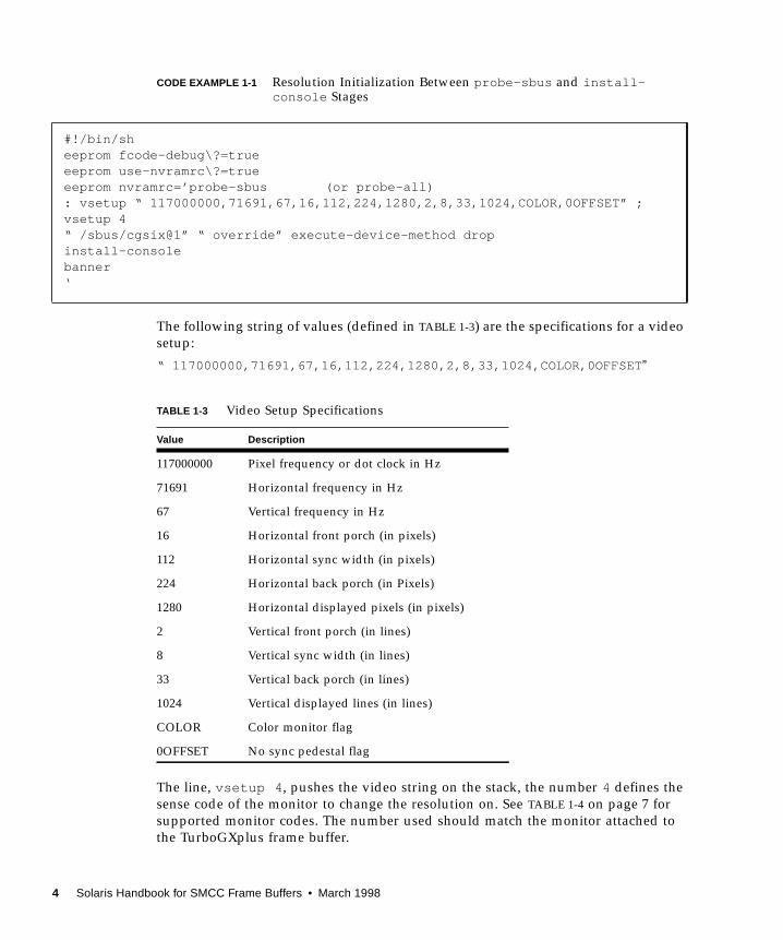
CODE EXAMPLE 1-1 Resolution Initialization Between probe-sbus and install-console Stages
The following string of values (defined in TABLE 1-3) are the specifications for a video
setup:
“ 117000000,71691,67,16,112,224,1280,2,8,33,1024,COLOR,0OFFSET ”
The line, vsetup 4 , pushes the video string on the stack, the number 4 defines the
sense code of the monitor to change the resolution on. See TABLE 1-4 on page 7 for
supported monitor codes. The number used should match the monitor attached to
the TurboGXplus frame buffer.
#!/bin/sheeprom fcode-debug\?=trueeeprom use-nvramrc\?=trueeeprom nvramrc=’probe-sbus (or probe-all): vsetup “ 117000000,71691,67,16,112,224,1280,2,8,33,1024,COLOR,0OFFSET” ;vsetup 4“ /sbus/cgsix@1” “ override” execute-device-method dropinstall-consolebanner‘
TABLE 1-3 Video Setup Specifications
Value Description
117000000 Pixel frequency or dot clock in Hz
71691 Horizontal frequency in Hz
67 Vertical frequency in Hz
16 Horizontal front porch (in pixels)
112 Horizontal sync width (in pixels)
224 Horizontal back porch (in Pixels)
1280 Horizontal displayed pixels (in pixels)
2 Vertical front porch (in lines)
8 Vertical sync width (in lines)
33 Vertical back porch (in lines)
1024 Vertical displayed lines (in lines)
COLOR Color monitor flag
0OFFSET No sync pedestal flag
4 Solaris Handbook for SMCC Frame Buffers • March 1998
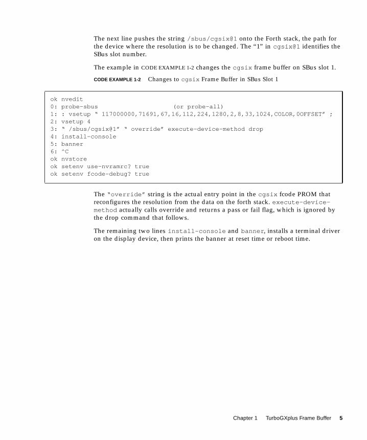
The next line pushes the string /sbus/cgsix@1 onto the Forth stack, the path for
the device where the resolution is to be changed. The “1” in cgsix@1 identifies the
SBus slot number.
The example in CODE EXAMPLE 1-2 changes the cgsix frame buffer on SBus slot 1.
CODE EXAMPLE 1-2 Changes to cgsix Frame Buffer in SBus Slot 1
The “override” string is the actual entry point in the cgsix fcode PROM that
reconfigures the resolution from the data on the forth stack. execute-device-method actually calls override and returns a pass or fail flag, which is ignored by
the drop command that follows.
The remaining two lines install-console and banner , installs a terminal driver
on the display device, then prints the banner at reset time or reboot time.
ok nvedit0: probe-sbus (or probe-all)1: : vsetup “ 117000000,71691,67,16,112,224,1280,2,8,33,1024,COLOR,0OFFSET” ;2: vsetup 43: “ /sbus/cgsix@1” “ override” execute-device-method drop4: install-console5: banner6: ^Cok nvstoreok setenv use-nvramrc? trueok setenv fcode-debug? true
Chapter 1 TurboGXplus Frame Buffer 5

Configuring Monitors Using a UNIX Script
CODE EXAMPLE 1-3 is a UNIX script used to configure the TurboGXplus for a
resolution of 1280 × 1024 at 67 Hz.
CODE EXAMPLE 1-3 UNIX Script Method
Configuring Monitors Using the PROM Method
CODE EXAMPLE 1-4 uses the PROM method to configure the TurboGXplus for a
resolution of 1280 × 1024 at 67 Hz.
CODE EXAMPLE 1-4 PROM Method
#!/bin/sheeprom fcode-debug\?=trueeeprom use-nvramrc\?=trueeeprom nvramrc=’probe-sbus (or probe-all): vsetup “ 117000000,71691,67,16,112,224,1280,2,8,33,1024,COLOR,0OFFSET” ;vsetup 4“ /sbus/cgsix@1” “ override” execute-device-method dropinstall-consolebanner‘
ok nvedit0: probe-sbus (or probe-all)1: : vsetup “ 117000000,71691,67,16,112,224,1280,2,8,33,1024,COLOR,0OFFSET” ;2: vsetup 43: “ /sbus/cgsix@1” “ override” execute-device-method drop4: install-console5: banner6: ^Cok nvstoreok setenv use-nvramrc? trueok setenv fcode-debug? true
6 Solaris Handbook for SMCC Frame Buffers • March 1998

TABLE 1-4 contains codes for TurboGXplus-supported resolutions:
Setting Up a Single Monitor Using the PROM
Method
CODE EXAMPLE 1-5 is an example of how to set up a TurboGXplus card in slot 2 to
1024 × 768 at 60 Hz using a 16-inch monitor.
CODE EXAMPLE 1-5 PROM Method for Single Monitor Setup
TABLE 1-4 TurboGXplus Resolution Codes
Resolution Code
1024 × 768 at 60 Hz “ 64125000,48286,60,16,128,160,1024,2,6,29,768,COLOR”
1024 × 768 at 70 Hz “ 74250000,56593,70,16,136,136,1024,2,6,32,768,COLOR”
1024 × 768 at 77 Hz “ 84375000,62040,77,32,128,176,1024,2,4,31,768,COLOR”
1152 × 900 at 66 Hz “ 94500000,61845,66,40,128,208,1152,2,4,31,900,COLOR”
1152 × 900 at 76 Hz “ 108000000,71808,76,32,128,192,1152,2,4,31,900,COLOR,0OFFSET”
1280 × 1024 at 67 Hz “ 117000000,71691,67,16,112,224,1280,2,8,33,1024,COLOR,0OFFSET”
1280 × 1024 at 76 Hz “ 135000000,81128,76,32,64,288,1280,2,8,32,1024,COLOR,0OFFSET”
1600 × 1280 at 76 Hz “ 216000000,101890,76,24,216,280,1600,2,8,50,1280,COLOR,0OFFSET”
ok nvedit 0: probe-sbus (or probe-all) 1: : vsetup “ 64125000,48286,60,16,128,160,1024,2,6,29,768,COLOR” ; 2: vsetup 6 3: “ /sbus/cgsix@2” “ override” execute-device-method drop 4: install-console 5: banner 6: ^Cok nvstoreok setenv use-nvramrc? trueok setenv fcode-debug? true
Chapter 1 TurboGXplus Frame Buffer 7

Setting Up a Single Monitor Using a UNIX Script
CODE EXAMPLE 1-6 is a UNIX script that sets a 1024 × 768 at 60 Hz for the
TurboGXplus card in slot 2.
CODE EXAMPLE 1-6 UNIX Script Method for Single Monitor Setup
Setting Up Multiple Monitors Using a UNIX
Script
CODE EXAMPLE 1-7 shows a UNIX script that sets up the TurboGXplus card in slot 1
to 1152 × 900 at 76 Hz, and another TurboGXplus card in slot 3 to 1280 × 1024 at 67
Hz using two 19-inch monitors.
CODE EXAMPLE 1-7 UNIX Script Method for Multiple Monitor Setup
#!/bin/sheeprom fcode-debug\?=trueeeprom nvramrc=’probe-sbus (or probe-all): vsetup “ 64125000,48286,60,16,128,160,1024,2,6,29,768,COLOR” ;vsetup 6“/sbus/cgsix@2” “ override” execute-device-method dropinstall-consolebanner‘eeprom use-nvramrc\?=true
#!/bin/sheeprom fcode-debug\?=trueeeprom nvramrc=’probe-sbus (or probe-all): vsetup1 “ 108000000,71808,76,32,128,192,1152,2,4,31,900,COLOR,0OFFSET” ;vsetup1 4“ /sbus/cgsix@1” “ override” execute-device-method drop: vsetup2 “ 117000000,71691,67,16,112,224,1280,2,8,33,1024,COLOR,0OFFSET” ;vsetup2 4“ /sbus/cgsix@3” “ override” execute-device-method dropinstall-consolebanner‘eeprom use-nvramrc\?=true
8 Solaris Handbook for SMCC Frame Buffers • March 1998

For more information on running multiple monitors, see Chapter 9, “Multiple
Monitors on a System.”
Chapter 1 TurboGXplus Frame Buffer 9

10 Solaris Handbook for SMCC Frame Buffers • March 1998

CHAPTER 2
S24 Frame Buffer
This chapter describes the S24™ Frame Buffer hardware options.
S24 Application Compatibility
The default visual of OpenWindows™ running on a system with an S24 Frame
Buffer is 24-bit TrueColor Visual. Some older 8-bit windows applications that were
written without consideration for portability may not work with the default 24-bit
visual of the S24 Frame Buffer.
Use the following workaround for these applications when starting OpenWindows.
As superuser, enter:
Note – tcx is the UNIX device name for the S24 Frame Buffer.
This workaround sets the default visual to 8 bits. All applications can now be
executed in 8-bit mode unless 24 bits or the best available visual are specifically
requested.
The following 24-bit visuals are exported in the Solaris™ software environment:
■ 24-bit TrueColor visual
■ 24-bit TrueColor Linear visual
■ 24-bit DirectColor visual
# openwin -dev /dev/fbs/tcx0 defdepth 8
11

The nonlinear visual is displayed before the linear visual on the screen visual list.
Nonlinear visual is the default 24-bit TrueColor visual. If you prefer gamma-
corrected 24-bit TrueColor as your default value, you can modify the order of the
visual list by using the tcxconfig command, which is provided in the SUNWtcxowpackage. Refer to the tcxconfig man page for more information.
Run tcxconfig at the console prompt before starting OpenWindows. . Start
OpenWindows after tcxconfig has set the linearity you want.
● To display the current default setting, enter tcxconfig without options.
■ linear means that the linear visual is the default 24-bit TrueColor visual, which
means that color is gamma corrected.
■ nonlinear means that the nonlinear visual is the default 24-bit TrueColor visual.
● To change the setting, enter the tcxconfig command with one of the aboveoptions:
S24 Frame Buffer Screen Resolutions
The S24 frame buffer in the SPARCstation™ 5 supports three different screen
resolutions. You may select a screen resolution other than the default value. This is
performed at the ok prompt.
# /usr/sbin/tcxconfiglinear
# /usr/sbin/tcxconfig nonlinear
12 Solaris Handbook for SMCC Frame Buffers • March 1998
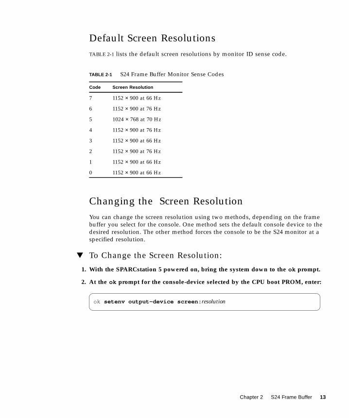
Default Screen Resolutions
TABLE 2-1 lists the default screen resolutions by monitor ID sense code.
Changing the Screen Resolution
You can change the screen resolution using two methods, depending on the frame
buffer you select for the console. One method sets the default console device to the
desired resolution. The other method forces the console to be the S24 monitor at a
specified resolution.
▼ To Change the Screen Resolution:
1. With the SPARCstation 5 powered on, bring the system down to the ok prompt.
2. At the ok prompt for the console-device selected by the CPU boot PROM, enter:
TABLE 2-1 S24 Frame Buffer Monitor Sense Codes
Code Screen Resolution
7 1152 × 900 at 66 Hz
6 1152 × 900 at 76 Hz
5 1024 × 768 at 70 Hz
4 1152 × 900 at 76 Hz
3 1152 × 900 at 66 Hz
2 1152 × 900 at 76 Hz
1 1152 × 900 at 66 Hz
0 1152 × 900 at 66 Hz
ok setenv output-device screen: resolution
Chapter 2 S24 Frame Buffer 13
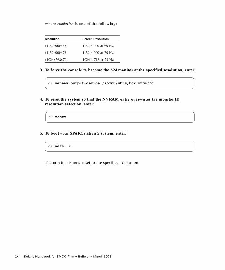
where resolution is one of the following:
3. To force the console to become the S24 monitor at the specified resolution, enter:
4. To reset the system so that the NVRAM entry overwrites the monitor IDresolution selection, enter:
5. To boot your SPARCstation 5 system, enter:
The monitor is now reset to the specified resolution.
resolution Screen Resolution
r1152x900x66 1152 × 900 at 66 Hz
r1152x900x76 1152 × 900 at 76 Hz
r1024x768x70 1024 × 768 at 70 Hz
ok setenv output-device / iommu/sbus/tcx: resolution
ok reset
ok boot -r
14 Solaris Handbook for SMCC Frame Buffers • March 1998

CHAPTER 3
ZX and TurboZX GraphicsAccelerator
This chapter describes how to change the ZX and TurboZX Graphics Accelerator
screen resolution to work properly with different monitors. Since the following
discussions are identical for the ZX and the TurboZX, the product name in this
chapter is shortened to ZX to simplify the discussion.
You can change the ZX screen resolution through the leoconfig program. See the
leoconfig (8) man page for more information.
Note – leo is the UNIX device name for the ZX and TurboZX Graphics Accelerators.
There are two elements to leoconfig : the leoconfig program and the
leoconfig script. The leoconfig program initializes the ZX Graphics Accelerator
and downloads microcode from the host CPU. The leoconfig program is normally
run as a part of the /etc/init.d/leoconfig script to download the ZX
microcode file and to complete ZX installation.
The leoconfig program is also useful to change the default screen configuration to
some other resolution, including stereo. The default screen resolution for the ZX
Graphics Accelerator is defined by the monitor ID code, which is read from the
monitor. If the monitor returns an unknown ID code, the ZX Graphics Accelerator
defaults to a screen resolution of 1152 × 900 at 66 Hz. While this resolution works
with all available monitors for the workstations supplied by Sun, some monitors can
take advantage of other resolutions available on the ZX Graphics Accelerator.
You can change in screen resolution in two ways:
■ Temporarily, by running the leoconfig program
■ So that it always boots up in the new resolution by modifying the leoconfigscript file
15
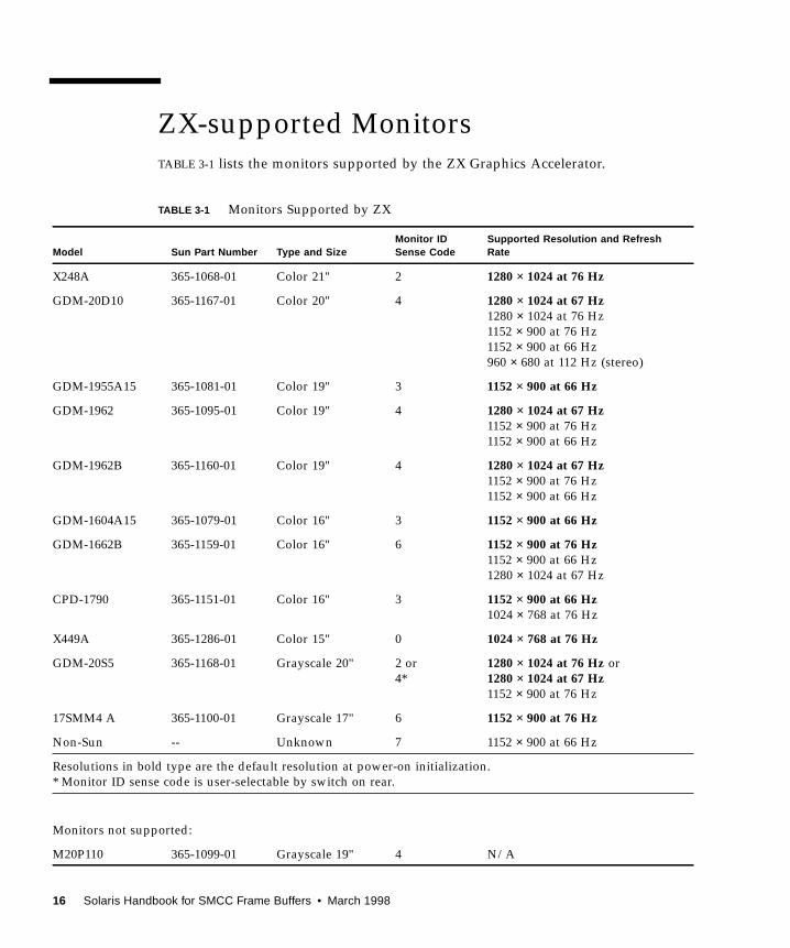
ZX-supported Monitors
TABLE 3-1 lists the monitors supported by the ZX Graphics Accelerator.
TABLE 3-1 Monitors Supported by ZX
Model Sun Part Number Type and SizeMonitor IDSense Code
Supported Resolution and RefreshRate
X248A 365-1068-01 Color 21" 2 1280 × 1024 at 76 Hz
GDM-20D10 365-1167-01 Color 20" 4 1280 × 1024 at 67 Hz1280 × 1024 at 76 Hz
1152 × 900 at 76 Hz
1152 × 900 at 66 Hz
960 × 680 at 112 Hz (stereo)
GDM-1955A15 365-1081-01 Color 19" 3 1152 × 900 at 66 Hz
GDM-1962 365-1095-01 Color 19" 4 1280 × 1024 at 67 Hz1152 × 900 at 76 Hz
1152 × 900 at 66 Hz
GDM-1962B 365-1160-01 Color 19" 4 1280 × 1024 at 67 Hz1152 × 900 at 76 Hz
1152 × 900 at 66 Hz
GDM-1604A15 365-1079-01 Color 16" 3 1152 × 900 at 66 Hz
GDM-1662B 365-1159-01 Color 16" 6 1152 × 900 at 76 Hz1152 × 900 at 66 Hz
1280 × 1024 at 67 Hz
CPD-1790 365-1151-01 Color 16" 3 1152 × 900 at 66 Hz1024 × 768 at 76 Hz
X449A 365-1286-01 Color 15" 0 1024 × 768 at 76 Hz
GDM-20S5 365-1168-01 Grayscale 20" 2 or
4*
1280 × 1024 at 76 Hz or
1280 × 1024 at 67 Hz1152 × 900 at 76 Hz
17SMM4 A 365-1100-01 Grayscale 17" 6 1152 × 900 at 76 Hz
Non-Sun -- Unknown 7 1152 × 900 at 66 Hz
Resolutions in bold type are the default resolution at power-on initialization.
* Monitor ID sense code is user-selectable by switch on rear.
Monitors not supported:
M20P110 365-1099-01 Grayscale 19" 4 N/A
16 Solaris Handbook for SMCC Frame Buffers • March 1998
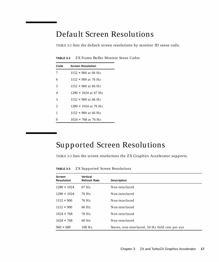
Default Screen Resolutions
TABLE 3-2 lists the default screen resolutions by monitor ID sense code.
Supported Screen Resolutions
TABLE 3-3 lists the screen resolutions the ZX Graphics Accelerator supports.
TABLE 3-2 ZX Frame Buffer Monitor Sense Codes
Code Screen Resolution
7 1152 × 900 at 66 Hz
6 1152 × 900 at 76 Hz
5 1152 × 900 at 66 Hz
4 1280 × 1024 at 67 Hz
3 1152 × 900 at 66 Hz
2 1280 × 1024 at 76 Hz
1 1152 × 900 at 66 Hz
0 1024 × 768 at 76 Hz
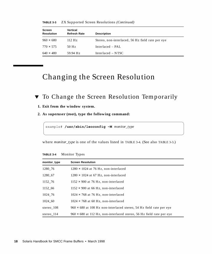
TABLE 3-3 ZX Supported Screen Resolutions
ScreenResolution
VerticalRefresh Rate Description
1280 × 1024 67 Hz Non-interlaced
1280 × 1024 76 Hz Non-interlaced
1152 × 900 76 Hz Non-interlaced
1152 × 900 66 Hz Non-interlaced
1024 × 768 76 Hz Non-interlaced
1024 × 768 60 Hz Non-interlaced
960 × 680 108 Hz Stereo, non-interlaced, 54 Hz field rate per eye
Chapter 3 ZX and TurboZX Graphics Accelerator 17
Changing the Screen Resolution
▼ To Change the Screen Resolution Temporarily
1. Exit from the window system.
2. As superuser (root), type the following command:
where monitor_type is one of the values listed in TABLE 3-4. (See also TABLE 3-3.)
960 × 680 112 Hz Stereo, non-interlaced, 56 Hz field rate per eye
770 × 575 50 Hz Interlaced – PAL
640 × 480 59.94 Hz Interlaced – NTSC
TABLE 3-4 Monitor Types
monitor_type Screen Resolution
1280_76 1280 × 1024 at 76 Hz, non-interlaced
1280_67 1280 × 1024 at 67 Hz, non-interlaced
1152_76 1152 × 900 at 76 Hz, non-interlaced
1152_66 1152 × 900 at 66 Hz, non-interlaced
1024_76 1024 × 768 at 76 Hz, non-interlaced
1024_60 1024 × 768 at 60 Hz, non-interlaced
stereo_108 960 × 680 at 108 Hz non-interlaced stereo, 54 Hz field rate per eye
stereo_114 960 × 680 at 112 Hz, non-interlaced stereo, 56 Hz field rate per eye
TABLE 3-3 ZX Supported Screen Resolutions (Continued)
ScreenResolution
VerticalRefresh Rate Description
example# /usr/sbin/leoconfig -M monitor_type
18 Solaris Handbook for SMCC Frame Buffers • March 1998
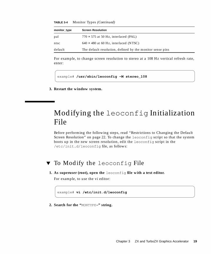
For example, to change screen resolution to stereo at a 108 Hz vertical refresh rate,
enter:
3. Restart the window system.
Modifying the leoconfig InitializationFile
Before performing the following steps, read “Restrictions to Changing the Default
Screen Resolution” on page 22. To change the leoconfig script so that the system
boots up in the new screen resolution, edit the leoconfig script in the
/etc/init.d/leoconfig file, as follows:
▼ To Modify the leoconfig File
1. As superuser (root), open the leoconfig file with a text editor.
For example, to use the vi editor:
2. Search for the “MONTYPE=” string.
pal 770 × 575 at 50 Hz, interlaced (PAL)
ntsc 640 × 480 at 60 Hz, interlaced (NTSC)
default The default resolution, defined by the monitor sense pins
TABLE 3-4 Monitor Types (Continued)
monitor_type Screen Resolution
example# /usr/sbin/leoconfig -M stereo_108
example# vi /etc/init.d/leoconfig
Chapter 3 ZX and TurboZX Graphics Accelerator 19

This string is usually one of the first lines in the file. The lines below are displayed.
There is one MONTYPE=line for each available screen configuration. By default, all
but one of the lines are commented out (with the # character).
3. Comment out the line that specifies the current screen configuration.
In the above example, comment out the “-m default ” line, as follows:
4. Delete the comment out character (#) from the line that supports your monitor.
The supported monitor types are listed in TABLE 3-3. (See also TABLE 3-1.)
For example, to change the screen resolution from the default to the higher
resolution of 1280 × 1024 at 76 Hz, delete the comment (the # character) from the
MONTYPE="-m 1280_76" line. The file should now look like this:
MONTYPE="-m default"# MONTYPE="-m 1280_76"# MONTYPE="-m 1280_67"# MONTYPE="-m 1152_76"# MONTYPE="-m 1152_66"# MONTYPE="-m 1024_76"# MONTYPE="-m 1024_60"# MONTYPE="-m stereo_108"# MONTYPE="-m stereo_114"# MONTYPE="-m pal"# MONTYPE="-m ntsc"
# MONTYPE="-m default"
# MONTYPE="-m default"MONTYPE="-m 1280_76"# MONTYPE="-m 1280_67"# MONTYPE="-m 1152_76"# MONTYPE="-m 1152_66"# MONTYPE="-m 1024_76"# MONTYPE="-m 1024_60"# MONTYPE="-m stereo_108"# MONTYPE="-m stereo_114"# MONTYPE="-m pal"# MONTYPE="-m ntsc"
20 Solaris Handbook for SMCC Frame Buffers • March 1998
5. Save the file and exit the editor.
In vi, press Esc and type wq.
6. Save all your work.
If you do not save your work, it will be lost when you reboot the system.
7. Exit from the window system.
If you are in a windowing environment, wait for the system prompt to appear after
you exit.
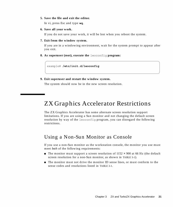
8. As superuser (root), execute the leoconfig program:
9. Exit superuser and restart the window system.
The system should now be in the new screen resolution.
ZX Graphics Accelerator Restrictions
The ZX Graphics Accelerator has some alternate screen resolution support
limitations. If you are using a Sun monitor and not changing the default screen
resolution by way of the leoconfig program, you can disregard the following
restrictions.
Using a Non-Sun Monitor as Console
If you use a non-Sun monitor as the workstation console, the monitor you use must
meet both of the following requirements:
■ The monitor must support a screen resolution of 1152 × 900 at 66 Hz (the default
screen resolution for a non-Sun monitor, as shown in TABLE 3-1).
■ The monitor must not drive the monitor ID sense lines, or must conform to the
sense codes and resolutions listed in TABLE 3-1.
example# /etc/init.d/leoconfig
Chapter 3 ZX and TurboZX Graphics Accelerator 21

Restrictions to Changing the Default Screen
Resolution
Some restrictions exist when changing the default screen resolution with the
leoconfig program.
When you modify the leoconfig initialization program to change from the default
screen resolution to a resolution of 1024 × 900 or less, excluding stereo, you will not
be able to see the bottom portion of the display area during boot up before the
window system starts. This means that you may not be able to see all of the start-up
messages or to see what you are typing when you log in. To avoid this problem you
must not set the monitor type to any one of the following:
■ 1024_76■ 1024_60■ pal■ ntsc
For applications that require lower resolutions, such as pal and ntsc , use a two-
headed system. With a two-headed system where the ZX monitor is not used as the
boot console, you may operate the ZX monitor in any of the supported screen
resolutions. For more information, see Chapter 9, “Multiple Monitors on a System.”
Stereo Connector
The stereo connector allows connection of stereo goggles to the ZX Graphics
Accelerator. The stereo connector is a female, three-conductor, mini-phone connector.
The male stereo connector that mates with the ZX Graphics Accelerator stereo
connector must be wired as shown in FIGURE 3-1.
22 Solaris Handbook for SMCC Frame Buffers • March 1998
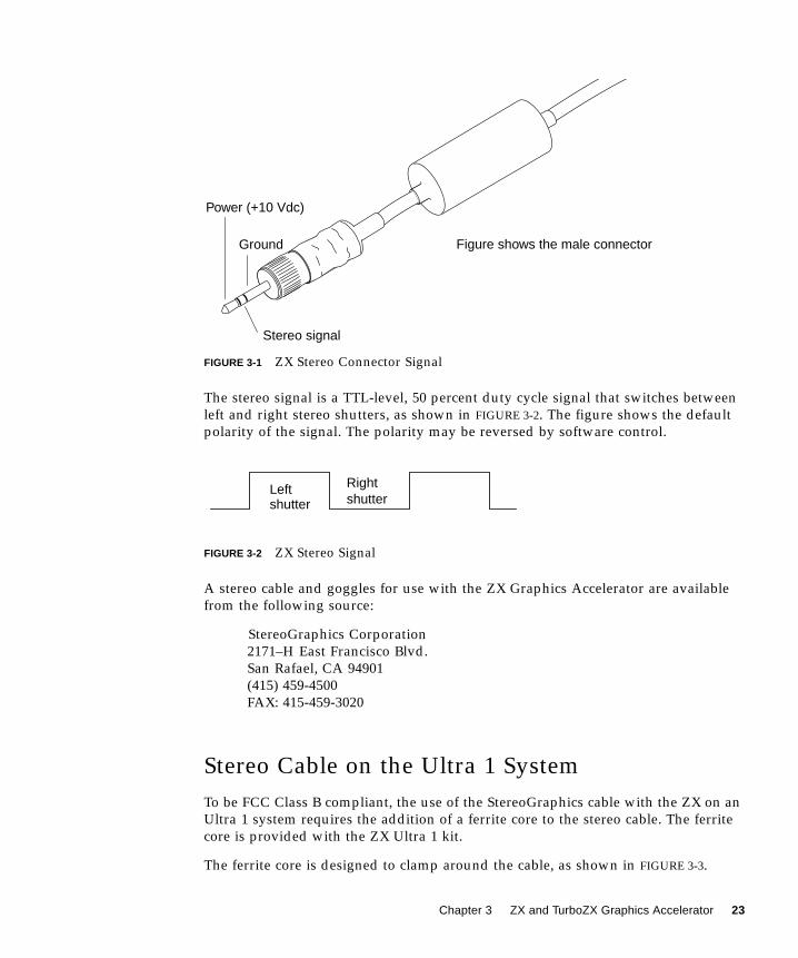
FIGURE 3-1 ZX Stereo Connector Signal
The stereo signal is a TTL-level, 50 percent duty cycle signal that switches between
left and right stereo shutters, as shown in FIGURE 3-2. The figure shows the default
polarity of the signal. The polarity may be reversed by software control.
FIGURE 3-2 ZX Stereo Signal
A stereo cable and goggles for use with the ZX Graphics Accelerator are available
from the following source:
StereoGraphics Corporation
2171–H East Francisco Blvd.
San Rafael, CA 94901
(415) 459-4500
FAX: 415-459-3020
Stereo Cable on the Ultra 1 System
To be FCC Class B compliant, the use of the StereoGraphics cable with the ZX on an
Ultra 1 system requires the addition of a ferrite core to the stereo cable. The ferrite
core is provided with the ZX Ultra 1 kit.
The ferrite core is designed to clamp around the cable, as shown in FIGURE 3-3.
Stereo signal
Figure shows the male connector
Power (+10 Vdc)
Ground
Leftshutter
Rightshutter
Chapter 3 ZX and TurboZX Graphics Accelerator 23
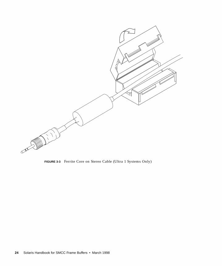
FIGURE 3-3 Ferrite Core on Stereo Cable (Ultra 1 Systems Only)
24 Solaris Handbook for SMCC Frame Buffers • March 1998

CHAPTER 3
SX Frame Buffer
This chapter describes how to change the display resolution on the SX Frame Buffer
(cgfourteen). If you want to run OpenWindows on a SPARCstation 10SX system or a
SPARCstation 20 system, you may need to perform additional configuration tasks
after the initial installation.
You can use the /usr/platforms/sun4m/sbin/cg14config utility to:
■ Specify a different screen resolution.
■ Change the values in the gamma lookup table.
Note – cg14 is the UNIX device name for the SX Frame buffer.
For more information, see the cg14config man page.
25

SX-supported Monitors
TABLE 3-1 lists the monitors supported by the SX Frame Buffer and the alternate
screen resolutions, if any, that each monitor supports.
TABLE 3-1 Monitors Supported by SX
Model Sun Part Number Type and SizeMonitor IDSense Code
Supported Resolution andRefresh Rate
GDM-20D10 365-1167-01 Color 20" 4 1152 × 900 at 76 Hz1280 × 1024 at 67 Hz
1280 × 1024 at 76 Hz
1152 × 900 at 66 Hz
GDM-1955A15 365-1081-01 Color 19" 3 1152 × 900 at 66 Hz
GDM-1962 365-1095-01 Color 19" 4 1152 × 900 at 76 Hz1280 × 1024 at 67 Hz
1152 × 900 at 66 Hz
GDM-1962B 365-1160-01 Color 19" 4 1152 × 900 at 76 Hz1280 × 1024 at 67 Hz1152 × 900 at 66 Hz
GDM-1604A15 365-1079-01 Color 16" 3 1152 × 900 at 66 Hz
GDM-1662B 365-1159-01 Color 16" 6 1152 × 900 at 76 Hz1152 × 900 at 66 Hz
1280 × 1024 at 67 Hz
CPD-1790 365-1151-01 Color 16" 3 1152 × 900 at 66 Hz1024 × 768 at 76 Hz
GDM-20S5 365-1168-01 Grayscale 20" 2 or
4*
1280 × 1024 at 67 Hz1152 × 900 at 76 Hz
17SMM4 A 365-1100-01 Grayscale 17" 6 1152 × 900 at 76 Hz
Non-Sun -- Unknown 7 1152 × 900 at 66 Hz
Resolutions in bold type are the default resolution at power-on initialization.
* Monitor ID sense code is user-selectable by switch on rear.
26 Solaris Handbook for SMCC Frame Buffers • March 1998

Default Screen Resolutions
TABLE 3-2 lists the default screen resolutions by monitor ID sense code.
TABLE 3-2 SX Frame Buffer Monitor Sense Codes
Code Screen Resolution
7 1152 × 900 at 66 Hz
6 1152 × 900 at 76 Hz
5 1024 × 768 at 60 Hz
4 1152 × 900 at 76 Hz
3 1152 × 900 at 66 Hz
2 1280 × 1024 at 76 Hz*
1 1600 × 1280 at 76 Hz*
0 1024 × 768 at 60 Hz
* The 4-Mbyte VSIMM drops to 8
bits per pixel at these resolutions.
Chapter 3 SX Frame Buffer 27
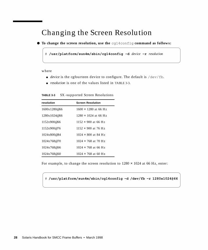
Changing the Screen Resolution
● To change the screen resolution, use the cg14config command as follows:
where
■ device is the cgfourteen device to configure. The default is /dev/fb .
■ resolution is one of the values listed in TABLE 3-3.
For example, to change the screen resolution to 1280 × 1024 at 66 Hz, enter:
TABLE 3-3 SX -supported Screen Resolutions
resolution Screen Resolution
1600x1280@66 1600 × 1280 at 66 Hz
1280x1024@66 1280 × 1024 at 66 Hz
1152x900@66 1152 × 900 at 66 Hz
1152x900@76 1152 × 900 at 76 Hz
1024x800@84 1024 × 800 at 84 Hz
1024x768@70 1024 × 768 at 70 Hz
1024x768@66 1024 × 768 at 66 Hz
1024x768@60 1024 × 768 at 60 Hz
# /usr/platform/sun4m/sbin/cg14config -d device -r resolution
# /usr/platform/sun4m/sbin/cg14config -d /dev/fb -r 1280x1024@66
28 Solaris Handbook for SMCC Frame Buffers • March 1998
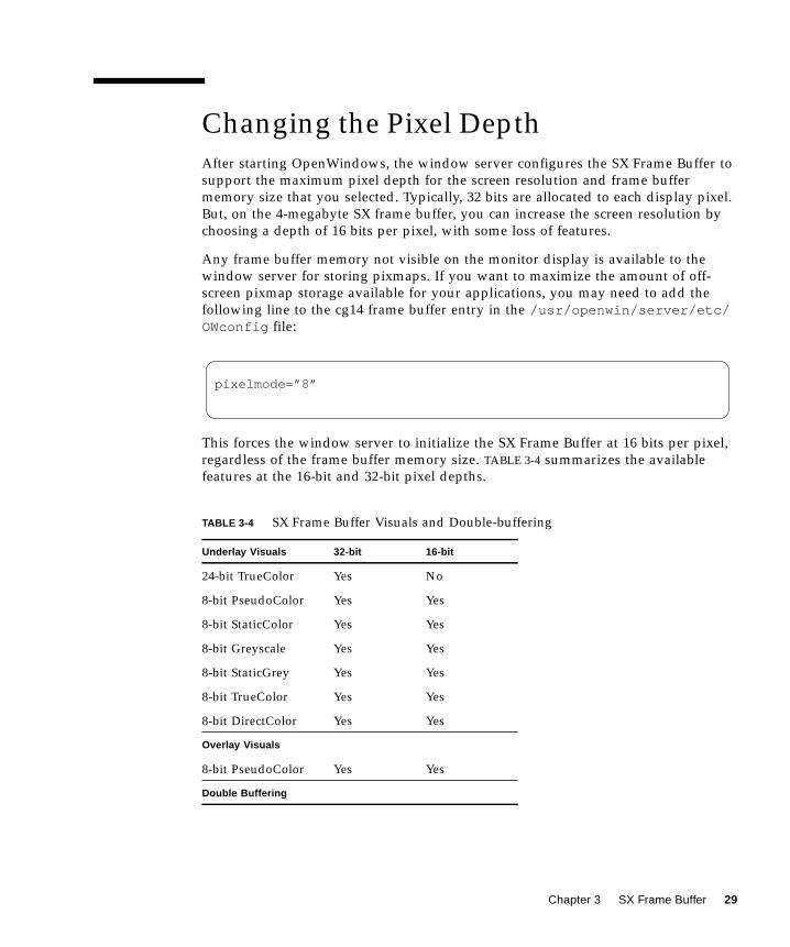
Changing the Pixel Depth
After starting OpenWindows, the window server configures the SX Frame Buffer to
support the maximum pixel depth for the screen resolution and frame buffer
memory size that you selected. Typically, 32 bits are allocated to each display pixel.
But, on the 4-megabyte SX frame buffer, you can increase the screen resolution by
choosing a depth of 16 bits per pixel, with some loss of features.
Any frame buffer memory not visible on the monitor display is available to the
window server for storing pixmaps. If you want to maximize the amount of off-
screen pixmap storage available for your applications, you may need to add the
following line to the cg14 frame buffer entry in the /usr/openwin/server/etc/OWconfig file:
This forces the window server to initialize the SX Frame Buffer at 16 bits per pixel,
regardless of the frame buffer memory size. TABLE 3-4 summarizes the available
features at the 16-bit and 32-bit pixel depths.
TABLE 3-4 SX Frame Buffer Visuals and Double-buffering
Underlay Visuals 32-bit 16-bit
24-bit TrueColor Yes No
8-bit PseudoColor Yes Yes
8-bit StaticColor Yes Yes
8-bit Greyscale Yes Yes
8-bit StaticGrey Yes Yes
8-bit TrueColor Yes Yes
8-bit DirectColor Yes Yes
Overlay Visuals
8-bit PseudoColor Yes Yes
Double Buffering
pixelmode=”8”
Chapter 3 SX Frame Buffer 29
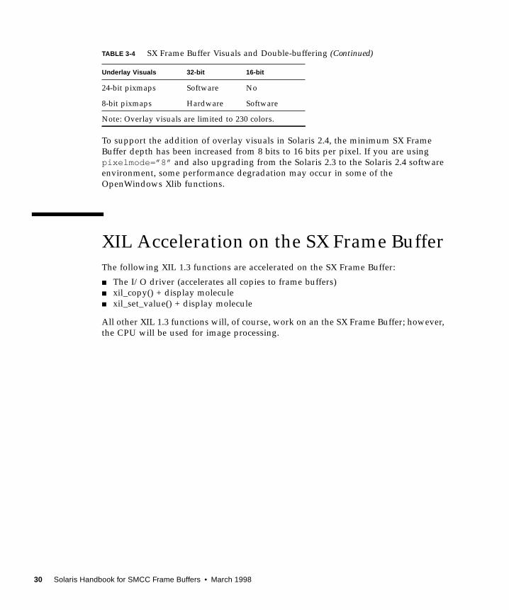
To support the addition of overlay visuals in Solaris 2.4, the minimum SX Frame
Buffer depth has been increased from 8 bits to 16 bits per pixel. If you are using
pixelmode=”8” and also upgrading from the Solaris 2.3 to the Solaris 2.4 software
environment, some performance degradation may occur in some of the
OpenWindows Xlib functions.
XIL Acceleration on the SX Frame Buffer
The following XIL 1.3 functions are accelerated on the SX Frame Buffer:
■ The I/O driver (accelerates all copies to frame buffers)
■ xil_copy() + display molecule
■ xil_set_value() + display molecule
All other XIL 1.3 functions will, of course, work on an the SX Frame Buffer; however,
the CPU will be used for image processing.
24-bit pixmaps Software No
8-bit pixmaps Hardware Software
Note: Overlay visuals are limited to 230 colors.
TABLE 3-4 SX Frame Buffer Visuals and Double-buffering (Continued)
Underlay Visuals 32-bit 16-bit
30 Solaris Handbook for SMCC Frame Buffers • March 1998

CHAPTER 5
Creator Graphics Accelerator
This chapter describes how to change the Creator and Creator 3D Graphics
Accelerator screen resolution to work properly with different monitors.
The Creator Graphics Accelerator family consists of three different versions: Series 1,
Series 2, and Series 3. The primary difference between each series is screen
resolution, but there are other performance differences also. The Creator Series 1 is
the base graphics accelerator in the family. The Creator Series 2 offers a performance
improvement over the Series 1 and additional screen resolutions. The Creator Series
3 offers the highest performance and the largest number of screen resolutions, plus
configurable gamma correction and extended overlay options.
You can change the Creator X11 screen and associated graphics hardware through
the ffbconfig utility. Options are specified on the command line. The specified
options are stored in the OWconfig file. You use these options to initialize the
Creator device the next time Xsun is run on that device. Updating options in the
OWconfig file provides persistence of these options across Xsun sessions and system
reboots.
Note – ffb is the UNIX device name for the Creator family of graphics accelerators.
Use the ffbconfig utility to specify the following:
■ Video mode (screen resolution and refresh rate)
■ Type of visuals (linear or nonlinear)
■ Whether to use 8-bit pseudocolor visual (overlay visual)
■ Whether linear visuals will be reported before their nonlinear counterparts in the
screen visuals list
■ How to set the default screen visual
■ How OpenGL visuals will be supported
■ Whether Server Overlay Visuals (SOV) will be available
■ The maximum number of Creator X channel pixels reserved for use as WIDs
31

■ Whether the pseudocolor overlay visual will come before the pseudocolor
underlay visual in the screen visuals list
For the Creator Series 3, the ffbconfig utility can be used to specify the following
additional functions:
■ Configurable gamma correction by specifying a gamma value or a file containing
a gamma-correction table
■ Extended overlay option enables a full 256-color overlay and hardware-
accelerated transparency visuals
Default Screen Resolutions
The Creator system reads the VESA standard Extended Display Identification Data
(EDID) from the monitor to determine the default screen resolution. If the EDID data
is not available for the monitor, the monitor ID sense code is used to determine the
default screen resolution.
TABLE 5-1 lists the default screen resolutions by monitor ID sense code.
If the Creator system is unable to determine the monitor type, such as for non-Sun
monitors, it defaults to a resolution of 1152 × 900 at 66 Hz.
TABLE 5-1 Creator Graphics Accelerator Monitor Sense Codes
Code Screen Resolution
7 1152 × 900 at 66 Hz
6 1152 × 900 at 76 Hz
5 1024 × 768 at 60 Hz
4 1280 × 1024 at 67 Hz
3 1152 × 900 at 66 Hz
2 1280 × 1024 at 76 Hz
1 1152 × 900 at 66 Hz
0 1024 × 768 at 77Hz
32 Solaris Handbook for SMCC Frame Buffers • March 1998

Supported Screen Resolutions
TABLE 5-2 lists the Creator-supported screen resolutions. Some resolutions are
supported only on Creator3D Series 2 or later.
TABLE 5-2 Creator-supported Screen Resolutions
ScreenResolution
VerticalRefresh Rate Description
Video ModeFormat
SymbolicName
1920 × 1200 70 Hz Non-interlaced, Hi-Res, Creator 3D, Series 2,3 1920x1200x70
1920 × 1080 72 Hz Non-interlaced, Hi-Res, Creator 3D, Series 2, 3 1920x1080x72
1920 × 1200 75 Hz Non-interlaced, Hi-Res, only Creator 3D, Series 3 1920x1200x75
1600 × 1280 76 Hz Non-interlaced, Hi-Res, Creator 3D, Series 2,3 1600x1280x76
1600 × 1000 76 Hz Non-interlaced, Hi-Res, Creator 3D, Series 2,3 1600x1000x76
1600 × 1000 66 Hz Non-interlaced, Hi-Res, Creator 3D, Series 2,3 1600x1000x66
1440 × 900 76 Hz Non-interlaced, Hi-Res, Creator 3D, Series 2,3 1440x900x76
1280 × 1024 76 Hz Non-interlaced 1280x1024x76 1280
1280 × 1024 67 Hz Non-interlaced 1280x1024x67
1280 × 1024 60 Hz Non-interlaced, Creator, Series 2,3 1280x1024x60
1280 × 1024 85 Hz Non-interlaced, Creator, Series 3 1280x1024x85
1280 × 800 76 Hz Non-interlaced, Creator, Series 2,3 1280x800x76
1152 × 900 76 Hz Non-interlaced 1152x900x76 1152
1152 × 900 66 Hz Non-interlaced 1152x900x66
1024 × 800 84 Hz Non-interlaced 1024x800x84
1024 × 768 77 Hz Non-interlaced 1024x768x77
1024 × 768 75 Hz Non-interlaced, Creator 3D, Series 2,3 1024x768x75
1024 × 768 70 Hz Non-interlaced 1024x768x70
1024 × 768 60 Hz SVGA 1024x768x60 svga
960 × 680 112 Hz Stereo, non-interlaced, 56 Hz field rate per eye 960x680x112s stereo
960 × 680 108 Hz Stereo, non-interlaced, 54 Hz field rate per eye 960x680x108s
768 × 575 50 Hz Interlaced – PAL 768x575x50i pal
640 × 480 60 Hz Interlaced – NTSC 640x480x60i ntsc
640 × 480 60 Hz Non-interlaced, Creator 3D, Series 2,3 640x480x60
Chapter 5 Creator Graphics Accelerator 33

Some monitors may not support some the resolutions supported by the Creator
system. You can get the list of resolutions supported by the Creator and the
connected monitor using the ffbconfig command.
Changing Screen Resolutions (-res )
▼ To Find Resolutions Supported By Creator and
the Connected Monitor
● Use the ffbconfig command as follows:
You can change the screen resolution temporarily as a test to determine if the
monitor supports the specified resolution.
Caution – Do not change screen resolution while the window system is running.
Changing screen resolution while the window system is running may put the screen
display in an unusable state.
▼ To Change Screen Resolutions Temporarily
● Use the ffbconfig command as follows:
See TABLE 5-2 for the list of video-mode options (see the “Video Mode Format” and
“Symbolic Name” columns in the table). You will have five seconds to confirm the
video mode by typing y.
ffbconfig -res \?
ffbconfig -res video-mode try
34 Solaris Handbook for SMCC Frame Buffers • March 1998
▼ To Change the Screen Resolution to Stereo
● Enter the following:
This changes the resolution to 960 × 680 at 112 Hz stereo the next time Xsun is run.
Changing Screen Visuals List
The X server screen visuals list can be altered through ffbconfig . The ffbconfigoptions in TABLE 5-3 can be used to configure the list of the exported visuals for the
specified device.
Changing the Visual List Order (-linearorder ,
-overlayorder )
By default, the nonlinear visual comes before the linear visual on the screen visual
list. You can modify the order of the visual list by using the ffbconfig command.
Most 3D applications require a linear visual. Some 3D applications do not search for
a linear visual using XSolarisGetVisualGamma (3). Instead, these applications
search the screen visual list for the first 24-bit TrueColor visual they find. To enable
TABLE 5-3 The Default Settings of the ffbconfig Visual Flags
Name Possible Values
Defaults inSolaris2.5.1/2.5.1 SHWP Defaults in Solaris 2.6
linearorder first/last last last
deflinear true/false false false
overlayorder first/last last last
defoverlay true/false false false
expvis enable/disable disable enable
sov enable/disable disable enable
ffbconfig -res stereo
Chapter 5 Creator Graphics Accelerator 35

these applications to run with the correct visual, use the -linearorder option to
change the visual list order so that the linear 24-bit TrueColor visual is the first one
the application finds.
The desired visual ordering in the screen visuals list will be available whenever the
window system is restarted.
● To change the setting, enter the ffbconfig command with one of the-linearorder options.
For example:
By default, the 8-bit PseudoColor visual comes before the 8-bit PseudoColor Overlay
visual on the screen visual list. You can modify the order of the visual list by using
the ffbconfig command.
Some applications that use the 8-bit PseudoColor Overlay visual, search the visual
list for the first 8-bit PseudoColor visual they find. To enable these applications to
run with the correct visual, use the -overlayorder option to change the visual list
order so that the 8-bit PseudoColor Overlay visual is the first 8-bit PseudoColor
visual the application finds.
The desired visual ordering in the screen visuals list will be available whenever the
window system is restarted.
● To change the setting, enter the ffbconfig command with one of the-overlayorder options.
For example:
Changing the Default Visual (-deflinear ,
-defoverlay )
By default, the 8-bit PseudoColor underlay visual is the default visual of the screen.
The default visual can be changed to either a linear underlay visual or an overlay
visual through ffbconfig .
ffbconfig -linearorder first
ffbconfig -overlayorder first
36 Solaris Handbook for SMCC Frame Buffers • March 1998

● To set the default visual to be a linear visual, enter the ffbconfig command asfollows:
● To set the default visual to be an overlay visual, enter the ffbconfig command asfollows:
Caution – Since there is no linear overlay visual, the user should not specify both
“-deflinear true ” and “-defoverlay true ” simultaneously, or the result will
be undefined.
Caution – Note that the visual ordering options (overlayorder and
linearorder ) are independent of the default visual options (defoverlay and
deflinear ). Moving the overlay visual groups, for example, to the front does not
automatically make it a default visual. Some applications make this assumption and
hence receive a “BADMATCH” X error when they try to match the colormap created
by the default visual and the first 8-bit PseudoColor visual they can find.
Changing OpenGL Visual Support (-expvis )
Solaris 2.5.1 SHWP supports the OpenGL visual expansion. With visual expansion,
five visual groups: the 8-bit PseudoColor, 24-bit TrueColor (Linear and Non-Linear),
24-bit DirectColor, and 8-bit PseudoColor Overlay, are expanded from a single visual
to multiple visual instances of the same visual type. Different instances of the same
visual groups represent different GLX capabilities (e.g. single-buffer or double-buffer
capable, monoscopic or stereoscopic capable, or a combination of both). The number
of visual instances depends on whether the X server is started in monoscopic or
stereoscopic mode, and also whether the device is a Creator or Creator 3D.
ffbconfig -deflinear true
ffbconfig -defoverlay true
Chapter 5 Creator Graphics Accelerator 37

▼ To Activate OpenGL Visual Support (Visual Expansion)
● Enter the following:
Changing SERVER_OVERLAY_VISUALS Support
(-sov )
SERVER_OVERLAY_VISUALS is one of the root window’s properties that contains
the visual ID, transparent type, transparent value, and layer of the server overlay
visuals (SOV) of the screen. You can toggle the advertisement of this property and
the export of the transparent server overlay visuals using ffbconfig .
▼ To Advertise SERVER_OVERLAY_PROPERTY and ExportSOV
● Enter the following:
Creator Series 3 Options
The following options apply only to the Creator Series 3 Graphics Accelerator.
Setting Gamma Correction (-g , -gfile )
Gamma correction may be set by specifying a gamma correction value or by
specifying a file that contains a gamma table.
ffbconfig -expvis enable
ffbconfig -sov enable
38 Solaris Handbook for SMCC Frame Buffers • March 1998

The -g option will set the gamma table entries based on the gamma value specified.
A gamma value of 2.22 represents linear gamma correction and matches the fixed
value on the Creator and Creator 3D products. This value is a per-screen value and
therefore all gamma corrected or linear visuals will use this value.
▼ To Set the Gamma Correction Using a Value
● Enter the following:
The -gfile option will set the gamma table entries explicitly from a file containing
three columns of 256 integers ranging from 0 to 255. The format is three integers
separated by a newline character. Each line contains the RGB value to be put in the
table for that entry. This value is a per-screen value and therefore all gamma-
corrected or linear visuals will use this value.
▼ To Set the Gamma Correction Using a File
● Enter the following:
Choosing Extended Overlay (-extovl )
Enabling the extended overlay option will switch the Series 3 Creator 3D from the
standard overlay mode supported on series 1 or 2 to the new extended overlay
functionality supported on Series 3. The extended overlay mode enables full 256-
color overlays and hardware-accelerated Server Overlay Visuals. The maximum
number of underlay Window IDs (WIDs) is increased from 32 to 64 and three new
overlay WIDs are provided. Extended Overlays can only be enabled on DBZ boards
running in a standard resolution.
ffbconfig -g 2.22
ffbconfig -gfile filename
Chapter 5 Creator Graphics Accelerator 39

▼ To Configure for Extended Overlay Mode
● Enter the following:
Times-Roman on Screen Visual List byVarious ffbconfig Visual Flags
Effect on the Default Visual and the Visual Group
Ordering
In summary, the appearance of the X server screen visual list can be changed to fit
the user’s needs using any of the ffbconfig visual flags (e.g., linearorder ,
overlayorder , expvis , sov , etc.). This section briefly shows the effect of these
visual options on the visual list.
Without any alteration using ffbconfig , the X server screen visual list can roughly
be categorized in the following visual groups and order:
■ 8-bit PseudoColor
■ 8-bit Miscellaneous (StaticColor, Non-linear StaticGray, etc)
■ 8-bit Linear StaticGray
■ 8-bit PseudoColor Overlay
■ 24-bit Non-linear TrueColor
■ 24-bit DirectColor
■ 24-bit Linear TrueColor
The default screen visual will be the 8-bit PseudoColor visual. The deflinear and
defoverlay options will alter this pointer to point to the first 8- or 24-bit linear
visual, depending on the X server depth when it starts up, and the first 8-bit overlay
visual, respectively. You can rearrange the entire “8-bit PseudoColor Overlay”
ffbconfig -extovl enable
40 Solaris Handbook for SMCC Frame Buffers • March 1998

group, the “8-bit Linear StaticGray” group, and the “24-bit Linear TrueColor” group
to be ahead of all other visual groups of the same depth by using the linearorderand overlayorder flags. For example, if you specify the following:
The screen visuals list will be rearranged in the following order:
■ 8-bit PseudoColor Overlay
■ 8-bit PseudoColor
■ 8-bit Miscellaneous (StaticColor, Non-linear StaticGray, etc.)
■ 8-bit Linear StaticGray
■ 24-bit Non-linear TrueColor
■ 24-bit DirectColor
■ 24-bit Linear TrueColor
Effect on the Number of Visual Instances Within
Selected Groups
The expvis flag will change the number of visual instances in the following visual
groups:
■ 8-bit PseudoColor
■ 8-bit PseudoColor Overlay
■ 24-bit Non-linear TrueColor
■ 24-bit DirectColor
■ 24-bit Linear TrueColor
The number of instances that expvis will alter depends on whether the monitor is
in monoscopic or stereoscopic resolution. In monoscopic resolution, if expvis is
enabled, the order of the screen visual groups will be preserved, but within each
group mentioned above, a “double-buffer capable” visual instance will be added. In
stereoscopic resolution, two additional visual instances: “double-buffer, stereo
capable” and “single-buffer, stereo capable”, will be added. The “double-buffer
capable” visual instances, if present, will always come ahead of the “single-buffer
capable” visual instances, and the monoscopic visual instances will always come
ahead of the stereoscopic ones.
ffbconfig -overlayorder first
Chapter 5 Creator Graphics Accelerator 41

For example, if you specify the following in stereoscopic resolution:
the screen visual list will be:
■ 8-bit PseudoColor Overlay (Mono, Stereo)
■ 8-bit PseudoColor (DB Mono, SB Mono, DB Stereo, SB Stereo)
■ 8-bit Miscellaneous (StaticColor, Non-linear StaticGray... etc)
■ 8-bit Linear StaticGray
■ 24-bit Linear TrueColor (DB Mono, SB Mono, DB Stereo, SB Stereo)
■ 24-bit Non-linear TrueColor (DB Mono, SB Mono, DB Stereo, SB Stereo)
■ 24-bit DirectColor (DB Mono, SB Mono, DB Stereo, SB Stereo)
Note – There is no double-buffer capable overlay visual instance.
Addition of the SERVER_OVERLAY_VISUALS
Property and the Transparent SOV Visuals in the
8-bit Overlay Group
Without the sov option being enabled, the only overlay visuals available are the
ones without transparency. Enabling the sov option will add the transparent SOV
visual instances into the screen visual list and also add the
SERVER_OVERLAY_VISUALS property to the root window property. The
transparent SOV visual instances belong to the “8-bit PseudoColor Overlay” visual
group. The SERVER_OVERLAY_VISUALS property will contain the visuals’ ID,
transparent type, value, and layer of all available overlay visuals of the screen.
For example, if you specify the following in stereoscopic resolution:
the screen visuals list will be:
■ 8-bit PseudoColor Overlay (Mono, Stereo, Mono SOV, Stereo SOV)
■ 8-bit PseudoColor (DB Mono, SB Mono, DB Stereo, SB Stereo)
■ 8-bit Miscellaneous (StaticColor, Non-linear StaticGray, etc.)
■ 8-bit Linear StaticGray
ffbconfig -overlayorder first -expvis enable
ffbconfig -overlayorder first -expvis enable -sov enable
42 Solaris Handbook for SMCC Frame Buffers • March 1998
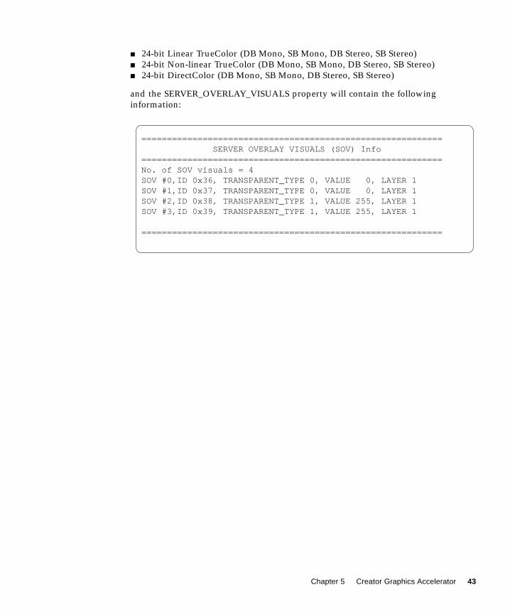
■ 24-bit Linear TrueColor (DB Mono, SB Mono, DB Stereo, SB Stereo)
■ 24-bit Non-linear TrueColor (DB Mono, SB Mono, DB Stereo, SB Stereo)
■ 24-bit DirectColor (DB Mono, SB Mono, DB Stereo, SB Stereo)
and the SERVER_OVERLAY_VISUALS property will contain the following
information:
=========================================================== SERVER OVERLAY VISUALS (SOV) Info===========================================================No. of SOV visuals = 4SOV #0,ID 0x36, TRANSPARENT_TYPE 0, VALUE 0, LAYER 1SOV #1,ID 0x37, TRANSPARENT_TYPE 0, VALUE 0, LAYER 1SOV #2,ID 0x38, TRANSPARENT_TYPE 1, VALUE 255, LAYER 1SOV #3,ID 0x39, TRANSPARENT_TYPE 1, VALUE 255, LAYER 1
===========================================================
Chapter 5 Creator Graphics Accelerator 43

Stereo Connector
The stereo connector allows connection of stereo goggles to the Creator Graphics
Accelerator. Two versions of stereo connector are used on the Creator Graphics
Accelerator: a female, three-conductor, mini-phone connector used on the Series 1
board and a seven-pin DIN connector used on the Series 2 board.
Creator Series 1 Stereo Connector
The stereo connector for the Creator Series 1 board is a female, three-conductor,
mini-phone connector, as shown in FIGURE 5-1.
FIGURE 5-1 Creator Series 1 Stereo Connector
Stereo signal
Figure shows the male connector
Power (+10 Vdc)
Ground
44 Solaris Handbook for SMCC Frame Buffers • March 1998
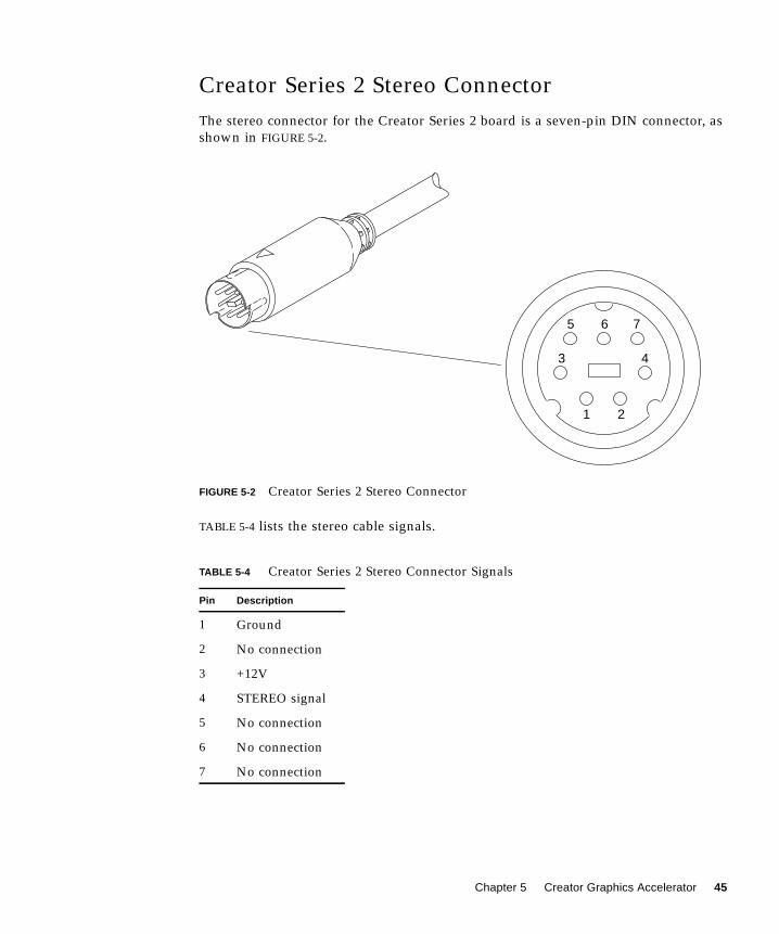
Creator Series 2 Stereo Connector
The stereo connector for the Creator Series 2 board is a seven-pin DIN connector, as
shown in FIGURE 5-2.
FIGURE 5-2 Creator Series 2 Stereo Connector
TABLE 5-4 lists the stereo cable signals.
TABLE 5-4 Creator Series 2 Stereo Connector Signals
Pin Description
1 Ground
2 No connection
3 +12V
4 STEREO signal
5 No connection
6 No connection
7 No connection
1
34
567
2
765
43
21
Chapter 5 Creator Graphics Accelerator 45
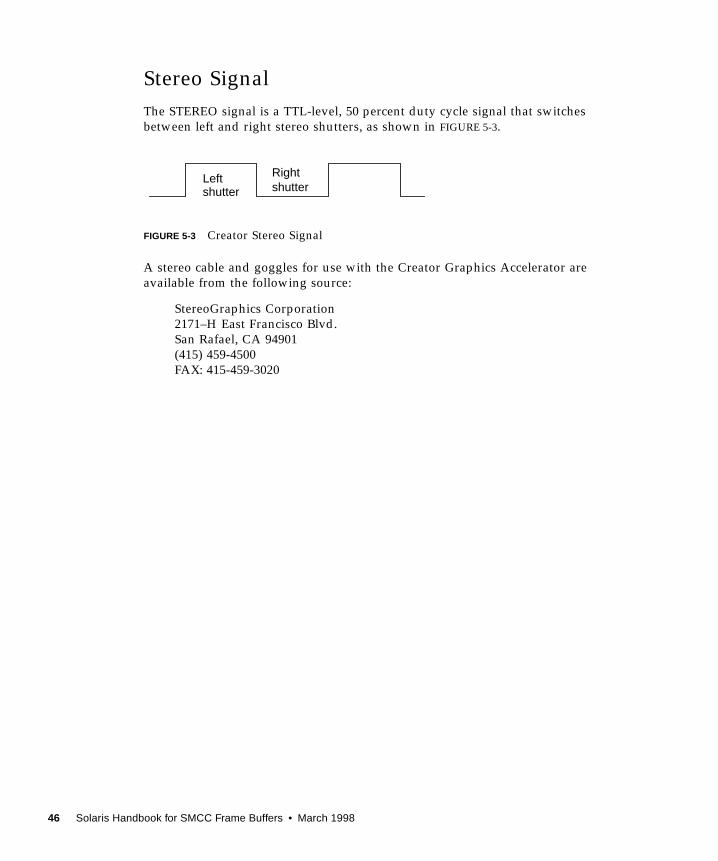
Stereo Signal
The STEREO signal is a TTL-level, 50 percent duty cycle signal that switches
between left and right stereo shutters, as shown in FIGURE 5-3.
FIGURE 5-3 Creator Stereo Signal
A stereo cable and goggles for use with the Creator Graphics Accelerator are
available from the following source:
StereoGraphics Corporation
2171–H East Francisco Blvd.
San Rafael, CA 94901
(415) 459-4500
FAX: 415-459-3020
Leftshutter
Rightshutter
46 Solaris Handbook for SMCC Frame Buffers • March 1998

CHAPTER 5
The Creator Window System
This chapter describes how the Solaris™ X11 window system is used with the
Creator and Creator 3D Graphics Accelerators.
The Creator accelerators are a high performance combination of the GX, SX, ZX, and
S24 display adaptors. Like the ZX graphics accelerator, the Creator accelerator
provides advanced frame buffer capabilities such as:
■ Multiple plane groups
■ Hardware double buffering
■ Non-interfering transparent overlays
■ 3D acceleration
■ Stereoscopic support
Like the SX accelerator, the Creator accelerator is an X-channel architecture display
adaptor. See “Creator Visuals.”
Like the GX accelerator, the Creator accelerator provides accelerated X11 rendering
operations and hardware cursor support. See “Cursor Management.”
Like the S24 accelerator, the Creator accelerator provides both gamma corrected and
uncorrected visuals. See “Creator Visuals.”
Like GX, SX, and ZX, the Creator accelerator supports multiple monitor video
modes. See “Device Configuration.”
The Creator accelerator comes in two configurations: SB (Creator) and DBZ (Creator
3D). SB stands for “Single Buffer” and DBZ stands for “Double Buffer plus Z.” Z
values are per-pixel depth information. These configurations differ in the amount of
video memory on the board. The Creator 3D accelerator provides additional
memory for hardware double buffering and 3D rendering.
47
Creator Visuals
The built-in factory default visual for the Creator accelerator is eight-bit
PseudoColor. The user can specify a different default visual using the defdepth and
defclass options of Xsun (1) and the -defoverlay and -deflinear options of
ffbconfig (1m).
Note – The Creator accelerator is also called the Fast Frame Buffer (FFB). The FFB
name is used in Creator software package names, loadable device pipeline module
names, the configuration program, and device man pages.
When starting OpenWindows, you can specify an alternate default visual using
standard OpenWindows command line options. Any of the exported visuals can be
selected as the default. For example, you can select the 24-bit TrueColor visual to be
the default by using the openwin defdepth 24 option (see Xsun (1)). A 24-bit
default helps to reduce colormap flashing.
List of Visuals
The Creator accelerator exports eleven visuals on the X11 screen visual list. You can
query these visuals using XGetVisualInfo (3) or XMatchVisualInfo (3). The
linearity of a visual can be queried using XSolarisGetVisualGamma (3). The
visuals are:
■ 8-bit PseudoColor
■ 8-bit StaticColor
■ 8-bit GrayScale
■ 8-bit StaticGray
■ 8-bit TrueColor
■ 8-bit DirectColor
■ 8-bit StaticGray Linear
■ 24-bit TrueColor
■ 24-bit DirectColor
■ 24-bit TrueColor Linear
■ 8-bit PseudoColor Overlay
Note – In the above list, a visual is non-linear (not gamma corrected) unless it is
explicitly specified to be linear. Also, an 8-bit visual resides in the Creator accelerator
underlay plane group unless it is explicitly specified to reside in the overlay. 24-bit
visuals are always underlay.
48 Solaris Handbook for SMCC Frame Buffers • March 1998
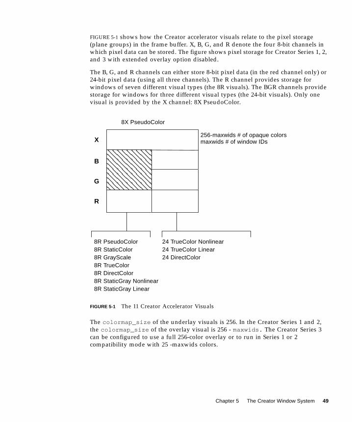
FIGURE 5-1 shows how the Creator accelerator visuals relate to the pixel storage
(plane groups) in the frame buffer. X, B, G, and R denote the four 8-bit channels in
which pixel data can be stored. The figure shows pixel storage for Creator Series 1, 2,
and 3 with extended overlay option disabled.
The B, G, and R channels can either store 8-bit pixel data (in the red channel only) or
24-bit pixel data (using all three channels). The R channel provides storage for
windows of seven different visual types (the 8R visuals). The BGR channels provide
storage for windows for three different visual types (the 24-bit visuals). Only one
visual is provided by the X channel: 8X PseudoColor.
FIGURE 5-1 The 11 Creator Accelerator Visuals
The colormap_size of the underlay visuals is 256. In the Creator Series 1 and 2,
the colormap_size of the overlay visual is 256 - maxwids. The Creator Series 3
can be configured to use a full 256-color overlay or to run in Series 1 or 2
compatibility mode with 25 -maxwids colors.
8R
8R PseudoColor8R StaticColor8R GrayScale8R TrueColor8R DirectColor8R StaticGray Nonlinear
8
24 TrueColor Nonlinear24 TrueColor Linear24 DirectColor
8X PseudoColor
8R StaticGray Linear
256-maxwids # of opaque colorsmaxwids # of window IDsX
B
G
R
Chapter 5 The Creator Window System 49

Overlay and Underlay Structure
The underlay 8-bit PseudoColor visual is sometimes referred to as the 8R visual
because the pixel is stored in the red channel of the frame buffer. The overlay 8-bit
PseudoColor visual is referred to as the 8X visual because it is stored in the X
channel.
The window pixels in the overlay visual do not interfere with the window pixels in
the underlay visuals. However, window pixels in the underlay visuals do interfere
with window pixels in the overlay visual. This is true because underlay windows
have color data which lives in the BGR (or just R) channels but they also have
window id (WID) data which resides in the X channel. This can cause an x11 expose
event (damage) to be generated.
When an overlay window is occluded by an underlay window, the WID portion of
the underlay data will corrupt the color data of the overlay window. When the
underlay window is moved away again, an x11 expose event will be sent out for the
damaged portion of the overlay window. This is different from the ZX accelerator,
which has mutually non-interfering underlays and overlays. Like the ZX accelerator,
the pixels of Creator 8-bit underlay windows interfere with the pixels of 24-bit
underlay windows.
The Creator accelerator follows an X-channel architecture. In this architecture, some
pixel values in the 8X plane group display opaque colors and some codes are used as
window IDs that control the display of pixels in the underlay visuals.
The Creator 3D Series 3 has an extended overlay mode that has non-interfering
overlays and underlays like the ZX accelerator. When this mode is enabled, the
window id planegroup no longer shares the X or overlay channel so that an
underlay window will not cause an x11 expose (damage) event.
The maxwids configuration option to ffbconfig (1m) specifies how many of the
overlay pixel values are to be used as hardware window IDs. See “Hardware
Window IDs” for details. The minimum legal value for maxwids is 1. The default
value is 32. Thus, the overlay visual is a partial visual because it has less than the
usual 256 colormap entries. For colormaps of this visual, if the client renders with a
pixel value greater than or equal to the specified number of colormap entries, no
error is generated and the colors displayed are undefined.
Comparison with the SX Accelerator
The visual architecture of the Creator accelerator is most similar to the CG14, the
display adaptor of the SX accelerator. CG14 is also an X-channel architecture display
adaptor that has 8-bit and 24-bit underlay visuals and a single 8-bit PseudoColor
overlay visual. However, there are two primary differences, as described in the
sections that follow.
50 Solaris Handbook for SMCC Frame Buffers • March 1998

Gamma Correction
The Creator accelerator has some visuals that are gamma-corrected and some that
are not. A gamma-corrected visual is called a linear visual. The linear visuals are:
■ 24-bit TrueColor Linear
■ 8-bit StaticGray Linear
Both linear and non-linear visuals are present on the X11 screen visual list, which
can be queried with XGetVisualInfo . Because linearity is not a visual property
recognized by the X11 core protocol, an extended routine must be called to
distinguish a linear visual from its nonlinear counterpart. This routine is
XSolarisGetVisualGamma . Refer to the XSolarisGetVisualGamma (1) man page
for further details.
CG14 does not have linear visuals like the Creator accelerator. It performs gamma
correction using a special Gamma LUT that affects the entire screen. Thus, it is not
possible on the CG14 to have both gamma-corrected and uncorrected 24-bit
windows on the screen at the same time. This is possible, however, on the Creator
accelerator.
Single Color LUT
CG14 has two hardware color LUTs. One is used by the 8-bit underlay visuals and
the other is used by the 8-bit overlay visual. In contrast, the Creator accelerator
Series 1 and 2 have only one hardware color LUT. This means that an overlay
window on the Creator accelerator will colormap flash against an 8-bit underlay
window unless precautions are taken to make sure that the colormaps of the two
windows use the same colors in the same pixel locations. Creator series 3 has four
hardware color LUTs whose allocation and sharing is managed by the Xserver.
When programming for the case where there is only one color LUT on a Creator
accelerator, take precautions to share overlay and underlay colors on transparent
overlay applications. Since the overlay visual is always a different visual from the
underlay visual, a transparent overlay application always requires at least two
separate colormaps: one for the overlay and one for the underlay. The overlay
window is usually a child of the underlay window and the pixels are correlated (i.e.,
spatially congruent) by the application. In this situation, when the mouse pointer is
inside the boundary of the underlay and overlay window pair, the overlay colormap
will be installed in the hardware CLUT and the underlay colormap will not be
installed. Thus, take care to ensure that underlay pixels display the correct colors
when viewed through the overlay colormap. This can be done by allocating colors in
the same position in both the underlay and overlay colormaps.
Chapter 5 The Creator Window System 51
Comparing Creator with the ZX Accelerator
Unlike the ZX accelerator, the built-in factory default visual on the Creator
accelerator is not an overlay. On the ZX accelerator, the default visual is the overlay
8-bit PseudoColor visual. But on the Creator accelerator, like the SX accelerator, it is
the 8-bit underlay PseudoColor visual. Thus, if you want to create applications with
pop-up windows that are non-damaging with underlay windows, you cannot
simply use the default visual. Instead, applications should call
XSolarisOvlSelectBestOverlay to find a non-damaging overlay visual. Refer
to the Solaris documentation on the OVL extension to X.
Note – XSolarisOvlSelectBestOverlay was first introduced in Solaris 2.4. If an
application needs to run on Solaris 2.3 or earlier as well as on Solaris 2.4, define the
external reference to this function as #pragma weak . The program can then check
the value of this symbol. If this symbol has the value of 0, then the program is
running on Solaris 2.3 or earlier. In this case, XSolarisOvlSelectBestOverlaycannot be called to find the overlay visual. Instead, the application can use
XGetVisualInfo to find the first 8-bit visual with less than 256 colormap entries.
However, this technique is specific to the Creator accelerator and is not portable to
other devices.
Window Manager Implications
Because the Creator accelerator default visual is not an overlay, problems occur
when overlay windows are not override-redirect (i.e. wrapped with a window
manager decoration window). The Solaris-supported window managers olwm, mwm,and dtwm always wrap toolkit subwindows with decoration windows in the default
visual. This occurs even if an application specifies a non-default visual for the pop-
up window.
For example, when the default visual is 8-bit underlay PseudoColor, the window
manager will wrap it with an 8-bit underlay decoration window even if an
application specifies to a toolkit that a pop-up window is to be placed in the 8-bit
overlay PseudoColor visual. Thus, the pop-up continues to damage other underlay
windows, which is not the intended effect.
Use the following workarounds to this limitation:
■ Require that the end user configure the default visual as the overlay visual by
typing the following before starting the window system:
/usr/sbin/ffbconfig -defoverlay true
52 Solaris Handbook for SMCC Frame Buffers • March 1998

Keep in mind that the overlay visual has less colormap entries than the underlay 8-
bit visual. Thus, the default colormap may fill up sooner, which may lead to
increased colormap flashing.
■ Rewrite the application to create override redirect pop-ups and manage them
directly through Xlib, bypassing the toolkit.
Hardware Color LUT Usage
The following visuals use a color LUT:
■ 8-bit PseudoColor
■ 8-bit StaticColor
■ 8-bit GrayScale
■ 8-bit TrueColor
■ 8-bit DirectColor
■ 24-bit DirectColor
■ 8-bit PseudoColor Overlay
On the Creator accelerators where there is only one color LUT, the colormaps of
these visuals colormap flash against each other. Refer to “Reducing Colormap
Flashing” for how to avoid colormap flashing.
The other Creator accelerator visuals don’t use color LUT resources. Colormaps of
these visuals never flash.
Reducing Colormap Flashing
The 24-bit TrueColor visual of the Creator accelerator can display over 16 million
colors simultaneously without colormap flashing. Furthermore, the Creator
rendering engine is optimized for 24-bit rendering. Consequently, it is very desirable
for users and X client programmers to use this visual.
Chapter 5 The Creator Window System 53

Notes to End Users
Even though 24-bit TrueColor offers fast rendering and no colormap flashing, the
built-in factory default visual on the Creator accelerator is 8-bit PseudoColor. This
was done to accommodate X applications that don’t handle a 24-bit visual properly.
It is better to have programs run and colormap flash than to not run at all.
Fortunately, the majority of desktop applications do run properly with this visual.
Users who desire less colormap flashing on their desktop can run the window
system with the default visual configured to 24-bit TrueColor. This is the
recommended mode of running the window system on the Creator accelerator.
● To run OpenWindows in this mode, use the following command:
● To run CDE in this mode, edit the /usr/dt/config/Xservers file and add“defdepth 24 ” to the appropriate X start-up command for your server.
Be aware of the following conditions when using this mode:
■ Some X applications cannot handle the 24-bit default. These type of programs
usually fail to run and issue a BadMatch error message. Other programs may core
dump or draw incorrect colors. If you encounter such an application, you can
diagnose the problem by rerunning the application under the 8-bit PseudoColor
default visual. If the program works, it probably cannot handle a 24-bit TrueColor
default visual. Contact the application supplier and request an upgraded
program. In the meantime, use the factory default 8-bit PseudoColor visual mode
until the application is fixed.
■ When the default visual depth is 24-bit, pixmaps and window backing store will
occupy four times the space as in an 8-bit depth. This usually does not increase
the working set of the server, but it does increase swap space. If you run
programs that use lots of pixmaps or backing store windows, stay in 8-bit mode.
Notes to Programmers
X client programmers should strive to write programs that are 24-bit clean, so that
they run properly when the default visual is 24-bit TrueColor.
A program might fail to be 24-bit clean for several reasons. Following are some
programming practices to avoid:
■ Do not assume that the default visual is 8-bit PseudoColor.
openwin -dev /dev/fbs/ffb0 defdepth 24
54 Solaris Handbook for SMCC Frame Buffers • March 1998

Some programs only run in 8-bit depth because they have been ported from 8-bit-
only systems and they have not been upgraded. Some programs might store their
lists of pixels in a 256-element array. Other programs may require a modifiable
colormap to perform colormap double buffering.
If your program requires 8-bit PseudoColor, check the depth and class of the default
visual. If it’s not the 8-bit PseudoColor visual, search the visual list until you find it.
■ Do not inherit the border pixel from the parent.
On a multiple plane group device like the Creator accelerator, the depth of the
window you are creating may not match the depth of the parent window (which is
often the root window). Unless you specify an explicit border pixel value, the border
pixel value of the window is inherited from the parent. If the depths differ,
XCreateWindow will fail with a BadMatch error. Always use XCreatewindowrather than XCreateSimpleWindow and explicitly specify a border pixel value.
Test your applications under both “defdepth 8 ” and “defdepth 24 ” modes of
the window system.
Hardware Window IDs
Each window requires a hardware Window ID (WID) to display the contents of its
pixels.
Note – Do not confuse the term Window ID used in this context with the X protocol
term window ID. An X protocol window ID is an XID which uniquely identifies a
window. A hardware window ID is a value rendered into the frame buffer that
controls window appearance.
Some overlay pixel codes are treated as opaque pixels, which display visible colors.
Other overlay pixel codes are used to control the display attributes of underlay
windows. These codes are referred to as hardware window IDs (WIDs). Specifically, a
certain number of codes at the high end of the colormap (toward 255) are used as
WIDs. The actual number of WIDs is configurable through the ffbconfig -maxwids option. For each overlay code used as a WID, the number of overlay
colormap entries is reduced by one. The default value of maxwids is 32, so there are
224 opaque pixel values in the overlay.
One hardware WID is always reserved for windows of the default visual. The
remaining WIDs are assigned on a priority basis to windows that have the following
characteristics:
■ Non-default visual
Chapter 5 The Creator Window System 55

■ Double buffered
■ Assigned a unique WID for the purposes of hardware WID clipping. (This
clipping technique is used by the Sun 3D rendering libraries).
Non-default visual windows can share a WID with other windows of the same
visual. However, like unique WID windows, double buffered windows always
require a unique dedicated WID.
Creating these types of windows reduces the number of other types of windows that
can be created. If all available WIDs are assigned, the call to XCreateWindow will
return a BadAlloc failure.
maxwids must be a power-of-two. Thus, legal values for maxwids are: 1, 2, 4, 8, 16,
and 32. The default value of maxwids is 32.
Reducing maxwids increases the number of opaque color pixels in the overlay visual
but reduces the number of XGL, double buffered, and non-default visual windows
that the user can create.
Cursor Management
The Creator accelerator has a hardware cursor. The image of this cursor is directly
mixed into the output video signal. A software cursor, on the other hand, must be
rendered into the frame buffer and the contents of the previous frame buffer must be
temporarily stored. A software cursor incurs more overhead than a hardware cursor.
A hardware cursor provides optimal interactive response when moving the cursor.
The maximum size of the Creator hardware cursor is 64 × 64. Cursors with an image
whose width or height is less than or equal to 64 use the hardware cursor.
Otherwise, they are rendered as software cursors.
The software cursor on the Creator accelerator is rendered in the overlay plane
group. Therefore, software cursors interfere with pixels of overlay windows but not
with pixels of underlay windows.
An X11 cursor has a foreground and background color that the client application
requests. The colors of hardware cursors are rendered exactly as they are requested.
However, the colors of software cursors may be approximations of the requested
colors.
56 Solaris Handbook for SMCC Frame Buffers • March 1998
Note – A bug in existing Solaris Visual graphics libraries means that software
cursors are not properly removed. To work around this bug, the cursor will, in the
presence of any DGA-grabbed window, be forced to be a hardware cursor, even if
this entails truncating the cursor image.
Hardware Double Buffering
Hardware double buffering is supported through MBX and XGL. MBX and XGL
double buffering cannot both be used on a window at the same time.
Hardware double buffering is provided for 8R windows on all the Creator
accelerator configurations. Hardware double buffering for 24-bit windows is only
provided on the Creator/DBZ (Creator3D) configuration. 8X overlay windows are
never hardware double buffered on any Creator accelerator configuration; 8X
windows are always software double buffered.
Activating hardware double buffering through MBX consumes one WID. This
reduces the number of other WID-consuming windows that can be created. See
“Hardware Window IDs.” If no WID is available, MBX falls back to software
buffering mode in which a copy from a back buffer pixmap to the window is used to
flip the buffers.
In MBX, the buffer flips occur synchronously. That is, the server request does not
return until the vertical retrace period of the monitor occurs and the buffer is
flipped. X11 clients may continue to run and send requests to the server, but will not
be processed until pending buffer flips are complete.
Device Configuration
Use the /usr/sbin/ffbconfig program to alter the Creator accelerator’s monitor
video mode, default visual, default linear order, and the number of WIDs. Refer to
the ffbconfig (1m) man page for details.
Attempts to grab stereo through DGA are rejected unless the monitor is configured
in a stereo video mode.
Chapter 5 The Creator Window System 57
When the “shared” OWconfig file is being updated via ffbconfig , an error occurs
if the /usr/openwin directory is remotely mounted. This occurs even though
ffbconfig is a setuid root program. This is because in UNIX, the root user of the
local machine is different from the root users on a remote machine. The workaround
is to log in to the remote machine to execute ffbconfig .
Performance Notes
The following sections contain performance notes for the Creator Accelerator on
various applications.
Direct Xlib
Direct Xlib is not supported on the Creator accelerator. The X shared memory
transport feature (new in Solaris 2.5) should be used instead. To enable shared
memory transport, set the following environment variables in the client
environment:
setenv DISPLAY :0setenv XSUNTRANSPORT shmemsetenv XSUNSMESIZE 512
Note – The last line specifies a client request buffer size of 512 kilobytes. Different
request buffer sizes can be specified. However, 512 is a good compromise between
the transport speed and the system memory resources consumed.
Applications that rely on XPutImage and Direct Xlib for fast pixel transfer into the
frame buffer should instead use the MITSHM extension function XShmPutImage on
the Creator accelerator. This function provides the fastest transfer of pixels into the
frame buffer when the client is on the same machine as the X server.
If you are using XShmPutImage to a 24-bit visual, you may need to increase the
amount of allocated shared memory beyond the default amount. See “The X11perf
Benchmark” for details.
58 Solaris Handbook for SMCC Frame Buffers • March 1998

The X11perf Benchmark
If you are running the x11perf benchmark when the default server visual is 24-bit
TrueColor, the -shmput<nn> tests will fail. This is because this test requires more
shared memory than that provided by the default shmsys configuration. The X11R5
version of x11perf version will core dump, while the X11R6 version will report an
error and make no measurement.
To run this test, you will need to increase the amount of shared memory.
● To increase the amount of shared memory, add the following line to /etc/system :
No Creator Pixel Copy Hardware
The Creator accelerator does not have hardware for copying pixels within the frame
buffer. Pixels are copied by reading the pixels into CPU registers and then writing
them back to the frame buffer. Thus, pixel copies within the frame buffer are CPU-
intensive. When the system is under heavy load, the performance of window
dragging operations may suffer. For example, the ShowMe Whiteboard “Snap
Region” image drag operation may slow down while an active SunVideo stream is
being rendered. This effect does not occur on a TurboGX accelerator, which has pixel
copy hardware.
Background None Window Transient Color
Effects
Dragging the imagetool image palette window with mouse shift-left over the main
imagetool window can leave areas of the main window temporarily cyan-colored.
These areas are quickly repaired, but persist long enough to be noticed. The effect is
particularly pronounced when the window being dragged is partially inside and
partially outside the imagetool main window. These effects occur because the
imagetool main window is an Xview WIN_TRANSPARENTwindow. This means the
background of the corresponding X window is set to None. For this type of window,
the server relies on the application to repair damaged areas after an occluding
window is moved. This method of damage repair is inherently slow because the
client must process damage events and send rendering requests.
set shmsys:shminfo_shmmax=8192000
Chapter 5 The Creator Window System 59

The imagetool image palette window is an 8-bit window. The pixel data resides in
the Creator accelerator 8-bit red channel. The background pixel value of this 8-bit
window is a small number, typically 0x02. The data in the red channel doesn't
damage data in the green and blue channels. The background of the main window
was white (0xffffff) but when the 8-bit window occludes, the pixel values are
0xffff02.
When the 8-bit window occludes the area, it is viewed as an 8-bit window. But when
the 8-bit window is moved, the server immediately changes the window ID values
in this region, indicating that the region is now to be viewed as a 24-bit window.
This happens before the background is repaired. So, for a moment, the old pixel
values in this region (0xffff02) are viewed as a 24-bit pixel. This pixel value is viewed
as pure blue + pure green, which forms cyan.
Note – This effect can also be seen on the SX frame buffer, although the SX frame
buffer stores its 8-bit windows in the blue channel, so the transient color is green +
red, which appears as yellow.
This effect is not as noticeable on the SX frame buffer, because it is more difficult to
detect a contrast difference between yellow and white. On the Creator accelerator
however, the difference between cyan and white is more pronounced. The effect also
takes longer to go away when the dragged window is partially outside the
imagetool window. This occurs because the Creator hardware has more rendering
state to maintain than the SX frame buffer; dragging outside the imagetool window
causes the window manager to continuously update the imagetool window header.
This causes text rendering operations to be interleaved with copy operations. And
since both operations use different rendering state, the state must be continually
loaded and reloaded into the Creator hardware context. Thus, the repair of the
transient color regions in on Creator in this situation is slower than the SX.
This example has dealt specifically with imagetool, but this will happen with any X
window whose background is set to None. A bug for this has been filed for
imagetool (Bug id 1215303).
To summarize, transient color effects like the one described above will occur on any
window that has Background set to None. Applications that use this type of window
should use some another background mode to avoid these effects. The X server can
then repair the damage soon after it occurs.
60 Solaris Handbook for SMCC Frame Buffers • March 1998

CHAPTER 7
XIL Acceleration on the CreatorGraphics Accelerator
This chapter describes the XIL functions that are specific to the Creator and
Creator3D Graphics Accelerators.
XIL is Sun’s foundation imaging and video library. Several important XIL functions
have been accelerated for the Ultra platforms using the UltraSPARC Visual
Instruction Set (VIS) and the Creator Graphics Accelerator.
XIL Data Types
XIL supports a very general image structure, but not all types of XIL images are
accelerated using VIS and Creator. The XIL data types supported in the VIS port are:
■ 1-, 2-, 3-, and 4-banded unsigned byte images
■ 1-, 2-, 3-, and 4-banded signed short images
■ Band-aligned child images
■ All regions of interest
■ XIL_PIXEL_SEQUENTIAL type images
61
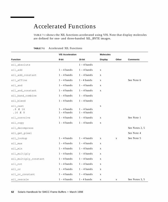
Accelerated Functions
TABLE 7-1 shows the XIL functions accelerated using VIS. Note that display molecules
are defined for one- and three-banded XIL_BYTE images.
TABLE 7-1 Accelerated XIL Functions
Function
VIS Acceleration Molecules
Comments8-bit 16-bit Display Other
xil_absolute 1 – 4 bands
xil_add 1 – 4 bands 1 – 4 bands x
xil_add_constant 1 – 4 bands 1 – 4 bands x
xil_affine 1 – 4 bands 1 - 4 bands x See Note 6
xil_and 1 – 4 bands 1 – 4 bands x
xil_and_constant 1 – 4 bands 1 – 4 bands x
xil_band_combine 1 – 4 bands 1 – 4 bands
xil_blend 1 – 4 bands 1 – 4 bands
xil_cast. 8 Æ 16. 16 Æ 8
1 – 4 bands
1 – 4 bands
1 – 4 bands
1 – 4 bands
x
xil_convolve 1 – 4 bands 1 – 4 bands x See Note 1
xil_copy 1 – 4 bands 1 – 4 bands x
xil_decompress See Notes 2, 5
xil_get_pixel See Note 4
xil_lookup 1 – 4 bands 1 – 4 bands x x See Note 5
xil_max 1 – 4 bands 1 – 4 bands x
xil_min 1 – 4 bands 1 – 4 bands x
xil_multiply 1 – 4 bands 1 – 4 bands x
xil_multiply_constant 1 – 4 bands 1 – 4 bands x
xil_not 1 – 4 bands 1 – 4 bands x
xil_or 1 – 4 bands 1 – 4 bands x
xil_or_constant 1 – 4 bands 1 – 4 bands x
xil_rescale 1 – 4 bands 1 - 4 bands x x See Notes 3, 5
62 Solaris Handbook for SMCC Frame Buffers • March 1998

Notes to Table 7-1:
Note 1: xil_convolve is accelerated for 3 × 3, 5 × 5, and 7 × 7 kernels.
Note 2: xil_decompress is accelerated for the following cases:
■ xil_decompress + color_convert (JPEG compressed image or sequence and
MPEG1 compressed sequence)
■ xil_decompress + color_convert + display (JPEG compressed image or
sequence and MPEG1 compressed sequence)
■ xil_decompress + color_convert + scale + display (MPEG1 compressed
sequence)
This decoder adheres to full-precision 24-bit CCIR 601 YCC to RGB709 color space
conversion.
There are a few instances when decompression of streams will not be accelerated.
■ Decompression of JPEG or MPEG1 streams which are not in one contiguous
buffer in memory is not accelerated. For example, streams split up using
xil_cis_put_bits_ptr might not be accelerated.
■ If one frame in a stream is not accelerated for some reason (e.g. the decompressor
encountered invalid data in the frame), subsequent frames in the stream will not
be accelerated.
xil_rotate 1 – 4 bands 1 - 4 bands x See Note 6
xil_scale 1 – 4 bands 1 – 4 bands x x See Note 5, 6
xil_set_pixel x See Note 4
xil_set_value 1 - 4 bands 1 – 4 bands x
xil_subtract 1 – 4 bands 1 – 4 bands x
xil_subtract_const 1 – 4 bands 1 – 4 bands x
xil_subtract_from_const 1 – 4 bands 1 – 4 bands x
xil_tablewarp x See Note 4
xil_threshold 1 – 4 bands 1 – 4 bands x x See Notes 3, 5
xil_transpose 1 – 4 bands 1 – 4 bands x
xil_xor 1 – 4 bands 1 – 4 bands x
xil_xor_const 1 – 4 bands 1 – 4 bands x
TABLE 7-1 Accelerated XIL Functions (Continued)
Function
VIS Acceleration Molecules
Comments8-bit 16-bit Display Other
Chapter 7 XIL Acceleration on the Creator Graphics Accelerator 63
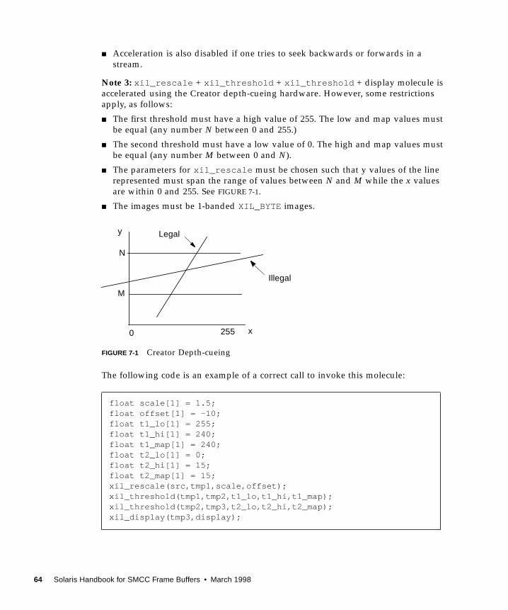
■ Acceleration is also disabled if one tries to seek backwards or forwards in a
stream.
Note 3: xil_rescale + xil_threshold + xil_threshold + display molecule is
accelerated using the Creator depth-cueing hardware. However, some restrictions
apply, as follows:
■ The first threshold must have a high value of 255. The low and map values must
be equal (any number N between 0 and 255.)
■ The second threshold must have a low value of 0. The high and map values must
be equal (any number M between 0 and N).
■ The parameters for xil_rescale must be chosen such that y values of the line
represented must span the range of values between N and M while the x values
are within 0 and 255. See FIGURE 7-1.
■ The images must be 1-banded XIL_BYTE images.
FIGURE 7-1 Creator Depth-cueing
The following code is an example of a correct call to invoke this molecule:
float scale[1] = 1.5;float offset[1] = -10;float t1_lo[1] = 255;float t1_hi[1] = 240;float t1_map[1] = 240;float t2_lo[1] = 0;float t2_hi[1] = 15;float t2_map[1] = 15;xil_rescale(src,tmp1,scale,offset);xil_threshold(tmp1,tmp2,t1_lo,t1_hi,t1_map);xil_threshold(tmp2,tmp3,t2_lo,t2_hi,t2_map);xil_display(tmp3,display);
N
M
y
x0 255
Legal
Illegal
64 Solaris Handbook for SMCC Frame Buffers • March 1998

However, if the same calling sequence is done with scale[1] = .40 , the molecule
will not be invoked because the line y = 0.40*x –10 only spans the range
y = –10 to y = (255*0.40) – 10 = 92 between x = 0 and x = 255. For the molecule to
execute, y must span at least the range y = 15 to y = 240 for x between 0 and 255.
Note 4: xil_get_pixel , xil_set_pixel , and xil_tablewarp are accelerated
only as display molecules. For xil_tablewarp , only interpolation ="nearest" is accelerated.
Note 5: All the molecules (other than a single xil function + display) that are
accelerated are as follows:
■ xil_decompress + xil_colorconvert [+ display] ( for JPEG)
■ xil_decompress + xil_colorconvert [+ display] ( for MPEG1)
■ xil_decompress + xil_colorconvert + xil_scale + display ( for
MPEG1)
■ xil_threshold + xil_threshold [+ display]
■ [xil_rescale] + [xil_threshold] + [xil_threshold] +[xil_cast] + display
■ xil_scale + xil_lookup + display (the accelerated molecules are for 8- or
16-bit bilinear scale followed by 8-to-8 bit or 16-to-8 bit lookup)
Note 6: There are some restrictions on the acceleration of xil_affine,xil_scale, and xil_rotate : xil_affine and xil_rotate are accelerated
only for 1-, 3-, and 4-banded images with "nearest " interpolation, and only for 1-
and 3-banded images with "bilinear " and "bicubic " interpolation. The
restriction for xil_scale is that in the case of interpolation = "general" the
size of the resampling kernels are limited to 8 × 8 for 8-bit images, and 8 × 4 for 16-
bit images.
Double Buffer Support
XIL supports double buffers on hardware where double buffers are available (e.g.
the Creator family). This section describes the double buffer support functions and
their usage.
The functions are:
xil_create_double_buffered_window
xil_set_active_buffer
xil_get_active_buffer
xil_swap_buffers
Chapter 7 XIL Acceleration on the Creator Graphics Accelerator 65
If you want to use a display image as a double-buffered display image, then instead
of using xil_create_from_window , use
xil_create_double_buffered_window to create the image. Trying to use
xil_create_double_buffered_window on hardware that does not support
double buffers returns a NULL device. The developer must catch the failure and call
xil_create_from_window instead.
If the image was created with xil_create_double_buffered_window and the
hardware supports double buffers, then XilBufferId makes sense and can take
two values, XIL_BACK_BUFFERand XIL_FRONT_BUFFER. For such a window, one
of the buffers is considered to be active at any time, and all functions writing to the
image will be writing the active buffer (for example a copy to the image will copy
the pixels to the active buffer of the image). On the other hand, the front buffer is the
one that is visible, i.e. displayed on the screen. At creation time, the active buffer is
XIL_BACK_BUFFER.
To start using the display image as a double buffered image after it has been created
by xil_create_double_buffered_window , you need to take no special action
since the active buffer is XIL_BACK_BUFFER. If the active buffer has been set to
XIL_FRONT_BUFFER, the image will not be used as a double-buffered image
(although imaging operations will not fail). To start using it again as a double-
buffered image, make a call like the following:
which will cause output to go to the back buffer. Note that in this case, the content of
the image will not be displayed (i.e., visible) without some action from the user. The
action to take is a call like the following:
This will make the content of the image visible. When the image is not needed as a
double-buffered image any longer, make a call like the following:
This ensures that the write and display buffers of the hardware are reset to their
default values.
xil_set_active_buffer(dest,XIL_BACK_BUFFER)
xil_swap_buffers(dest)
xil_set_active_buffer(dest,XIL_FRONT_BUFFER)
66 Solaris Handbook for SMCC Frame Buffers • March 1998

The following is a typical code segment for using double buffers:
dest =xil_create_double_buffered_window(state,display,dwindow);...for (i=0; i<repeat; i++) {...xil_lookup(src,dest,lut);xil_swap_buffers(dest);}xil_set_active_buffer(dest,XIL_FRONT_BUFFER);
Chapter 7 XIL Acceleration on the Creator Graphics Accelerator 67

68 Solaris Handbook for SMCC Frame Buffers • March 1998

CHAPTER 8
PGX Graphics Accelerator
This chapter describes how to change the display resolution on the PGX Graphics
Accelerator.
You can change the PGX screen and associated graphics hardware through the
m64config utility. Options are specified on the command line. The specified options
can be stored in the OWconfig file to provide persistence of the options across
window system sessions and system reboots.
Use the m64config utility to:
■ Specify the video mode (screen resolution and refresh rate).
■ Specify the OWconfig file to update.
■ Reset all option values to their default values.
■ Print the current values of all PGX options in the OWconfig file.
■ Print the PGX hardware configuration.
Note – m64 is the UNIX device name for the PGX Graphics Accelerator.
69

Supported Screen Resolutions
TABLE 8-1 lists the screen resolutions that are supported by the PGX Graphics
Accelerator.
Changing the Screen ResolutionTemporarily
This example changes the screen resolution temporarily. It can be used to verify that
the monitor supports the specified resolution.
TABLE 8-1 PGX-supported Screen Resolutions
ScreenResolution
VerticalRefresh Rate Description
1600 × 1000 76 Hz Non-interlaced
1600 × 1000 66 Hz Non-interlaced
1440 × 900 76 Hz Non-interlaced
1280 × 1024 76 Hz Non-interlaced
1280 × 1024 75 Hz Non-interlaced
1280 × 1024 67 Hz Non-interlaced
1280 × 1024 60 Hz Non-interlaced
1280 × 800 76 Hz Non-interlaced
1152 × 900 76 Hz Non-interlaced
1152 × 900 66 Hz Non-interlaced
1024 × 768 75 Hz Non-interlaced
1024 × 768 70 Hz Non-interlaced
1024 × 768 60 Hz SVGA (non-interlaced)
800 × 600 75 Hz Non-interlaced
768 × 575 50 Hz PAL (interlaced)
640 × 480 60 Hz NTSC (interlaced)
70 Solaris Handbook for SMCC Frame Buffers • March 1998
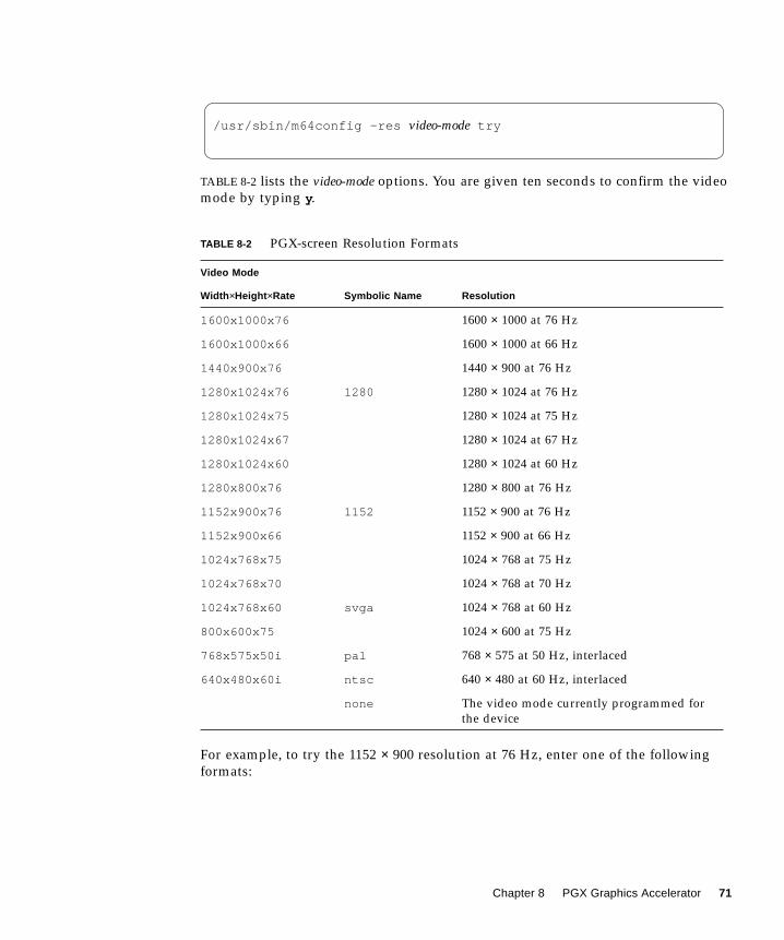
TABLE 8-2 lists the video-mode options. You are given ten seconds to confirm the video
mode by typing y.
For example, to try the 1152 × 900 resolution at 76 Hz, enter one of the following
formats:
TABLE 8-2 PGX-screen Resolution Formats
Video Mode
Width ×Height ×Rate Symbolic Name Resolution
1600x1000x76 1600 × 1000 at 76 Hz
1600x1000x66 1600 × 1000 at 66 Hz
1440x900x76 1440 × 900 at 76 Hz
1280x1024x76 1280 1280 × 1024 at 76 Hz
1280x1024x75 1280 × 1024 at 75 Hz
1280x1024x67 1280 × 1024 at 67 Hz
1280x1024x60 1280 × 1024 at 60 Hz
1280x800x76 1280 × 800 at 76 Hz
1152x900x76 1152 1152 × 900 at 76 Hz
1152x900x66 1152 × 900 at 66 Hz
1024x768x75 1024 × 768 at 75 Hz
1024x768x70 1024 × 768 at 70 Hz
1024x768x60 svga 1024 × 768 at 60 Hz
800x600x75 1024 × 600 at 75 Hz
768x575x50i pal 768 × 575 at 50 Hz, interlaced
640x480x60i ntsc 640 × 480 at 60 Hz, interlaced
none The video mode currently programmed for
the device
/usr/sbin/m64config -res video-mode try
Chapter 8 PGX Graphics Accelerator 71
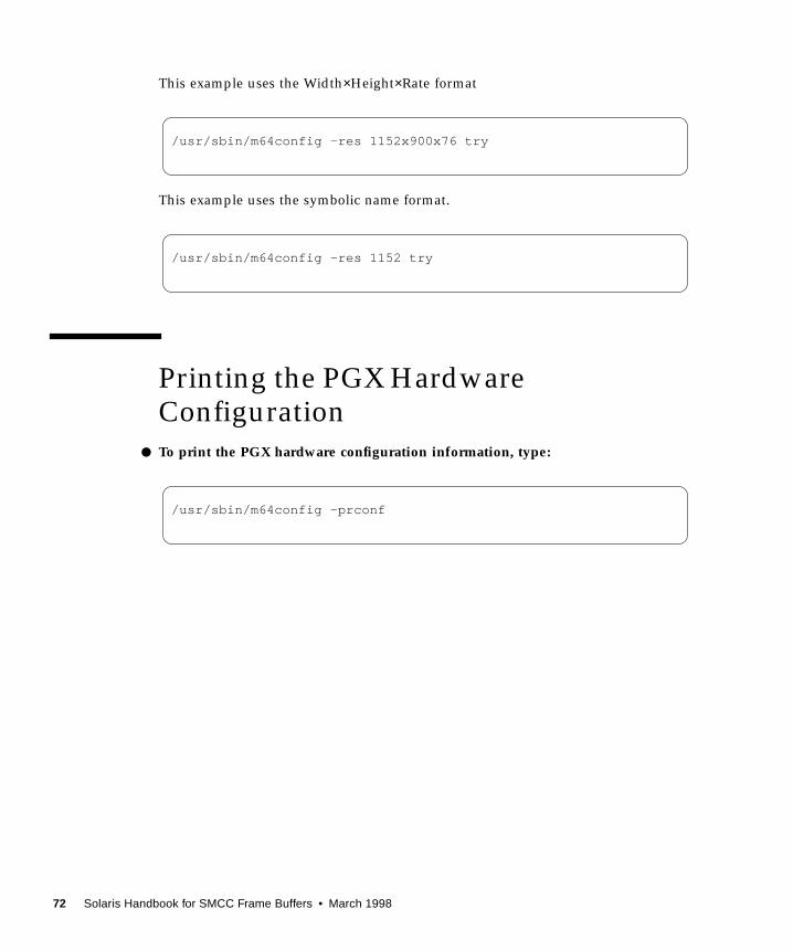
This example uses the Width×Height×Rate format
This example uses the symbolic name format.
Printing the PGX HardwareConfiguration
● To print the PGX hardware configuration information, type:
/usr/sbin/m64config -res 1152x900x76 try
/usr/sbin/m64config -res 1152 try
/usr/sbin/m64config -prconf
72 Solaris Handbook for SMCC Frame Buffers • March 1998
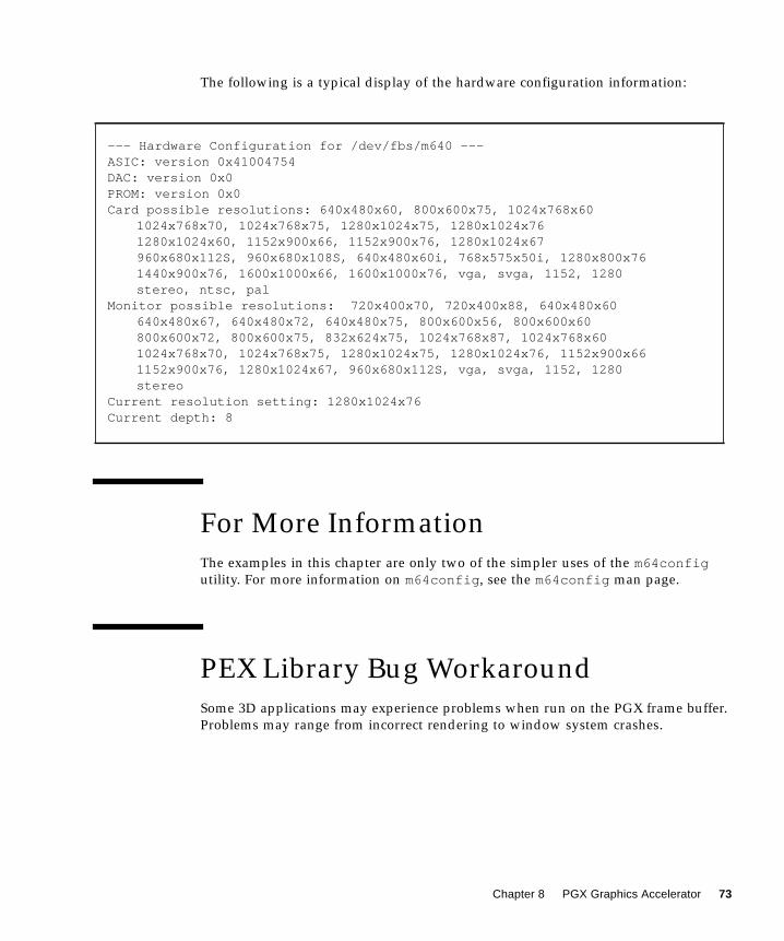
The following is a typical display of the hardware configuration information:
For More Information
The examples in this chapter are only two of the simpler uses of the m64configutility. For more information on m64config , see the m64config man page.
PEX Library Bug Workaround
Some 3D applications may experience problems when run on the PGX frame buffer.
Problems may range from incorrect rendering to window system crashes.
--- Hardware Configuration for /dev/fbs/m640 ---ASIC: version 0x41004754DAC: version 0x0PROM: version 0x0Card possible resolutions: 640x480x60, 800x600x75, 1024x768x60
1024x768x70, 1024x768x75, 1280x1024x75, 1280x1024x761280x1024x60, 1152x900x66, 1152x900x76, 1280x1024x67960x680x112S, 960x680x108S, 640x480x60i, 768x575x50i, 1280x800x761440x900x76, 1600x1000x66, 1600x1000x76, vga, svga, 1152, 1280stereo, ntsc, pal
Monitor possible resolutions: 720x400x70, 720x400x88, 640x480x60640x480x67, 640x480x72, 640x480x75, 800x600x56, 800x600x60800x600x72, 800x600x75, 832x624x75, 1024x768x87, 1024x768x601024x768x70, 1024x768x75, 1280x1024x75, 1280x1024x76, 1152x900x661152x900x76, 1280x1024x67, 960x680x112S, vga, svga, 1152, 1280stereo
Current resolution setting: 1280x1024x76Current depth: 8
Chapter 8 PGX Graphics Accelerator 73
The work-around for these problems is to set the environment variable XGLNOPEX
before executing any 3D applications. For example:
You do not have to assign any particular value to this environment variable, just
create it.
setenv XGLNOPEX
74 Solaris Handbook for SMCC Frame Buffers • March 1998
CHAPTER 9
Multiple Monitors on a System
This chapter describes how to use multiple monitors on a SPARCstation system.
Skip this chapter if you do not run multiple monitors on your system.
Most SPARCstations and UltraSPARC systems support multiple monitor
configurations, providing that additional SBus slots (or PCI slots for some systems)
are available.
The procedures described in this chapter require some knowledge of UNIX and basic
editing tools such as vi or emacs.
Multiple Monitor Configuration
When the system is booted, it looks for the sbus-probe-list , which determines
the order in which the SBus devices are addressed. For the SPARCstation 10, SBus
address f is reserved for the CPU and should always be the first address in the
sbus-probe-list .
The addressing numbers are 0, 1, 2, and 3. However, 0 is reserved for the CPU and
should always be the first address in the sbus-probe-list for all SPARCstation
systems except the SPARCstation 10 system.
75

● To determine the system information and sbus-probe-list , type:
The following system information and sbus-probe-list (starting with f ) will be
displayed if you have a SPARCstation 10 system:
Device File Names
If you are using OpenWindows™ software on multiple monitors, you should be
familiar with the way frame buffer devices are assigned to UNIX device file names.
Multiple frame buffers used with OpenWindows software require that you supply
UNIX device file names for frame buffers on the command line when either is
started.
The UNIX boot messages identify the frame buffer as /dev/fb (where fb is the type
of frame buffer). The /dev/fb usually has another device file name such as
/dev/fbs/cgsix0 , /dev/fbs/bwtwo0 , or /dev/fbs/leo0 , depending on the
type of frame buffer. When a second frame buffer is added, the system decides
which is /dev/fb based on the SBus slot number of each frame buffer and the
sbus-probe-list EEPROM variable. The /dev/fb is the frame buffer in the first
SBus slot defined in the sbus-probe-list .
If a TurboGXplus card is added to the system with an existing GX frame buffer, the
sbus-probe-list also determines which is /dev/fbs/cgsix0 and which is /dev/fbs/cgsix1 .
% eeprom . . .sbus-probe-list=0123
. .
% eeprom . . .sbus-probe-list=f0123
. .
76 Solaris Handbook for SMCC Frame Buffers • March 1998
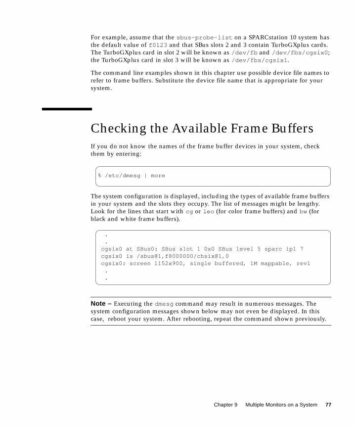
For example, assume that the sbus-probe-list on a SPARCstation 10 system has
the default value of f0123 and that SBus slots 2 and 3 contain TurboGXplus cards.
The TurboGXplus card in slot 2 will be known as /dev/fb and /dev/fbs/cgsix0 ;
the TurboGXplus card in slot 3 will be known as /dev/fbs/cgsix1 .
The command line examples shown in this chapter use possible device file names to
refer to frame buffers. Substitute the device file name that is appropriate for your
system.
Checking the Available Frame Buffers
If you do not know the names of the frame buffer devices in your system, check
them by entering:
The system configuration is displayed, including the types of available frame buffers
in your system and the slots they occupy. The list of messages might be lengthy.
Look for the lines that start with cg or leo (for color frame buffers) and bw (for
black and white frame buffers).
Note – Executing the dmesg command may result in numerous messages. The
system configuration messages shown below may not even be displayed. In this
case, reboot your system. After rebooting, repeat the command shown previously.
% /etc/dmesg | more
. .cgsix0 at SBus0: SBus slot 1 0x0 SBus level 5 sparc ipl 7cgsix0 is /sbus@1,f8000000/chsix@1,0cgsix0: screen 1152x900, single buffered, 1M mappable, rev1 . .
Chapter 9 Multiple Monitors on a System 77
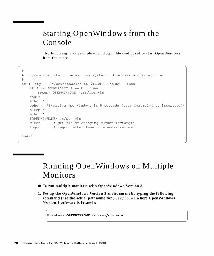
Starting OpenWindows from theConsole
The following is an example of a .login file configured to start OpenWindows
from the console.
Running OpenWindows on MultipleMonitors
● To run multiple monitors with OpenWindows Version 3
1. Set up the OpenWindows Version 3 environment by typing the followingcommand (use the actual pathname for /usr/local where OpenWindowsVersion 3 software is located):
## if possible, start the windows system. Give user a chance to bail out#if ( `tty` == “/dev/console” && $TERM == “sun” ) then
if ( ${?OPENWINHOME} == 0 ) thensetenv OPENWINHOME /usr/openwin
endifecho ““echo -n “Starting OpenWindows in 5 seconds (type Control-C to interrupt)”sleep 5echo ““$OPENWINHOME/bin/openwinclear # get rid of annoying cursor rectanglelogout # logout after leaving windows system
endif
% setenv OPENWINHOME /usr/local/openwin
78 Solaris Handbook for SMCC Frame Buffers • March 1998

2. Verify that a device file already exists for the desired frame buffer by typing:
If the device file already exists, a message similar to the one shown below is
displayed. If so, skip Steps 3, 4, and 5 and go to Step 6. If the “not found” message
is displayed, continue to Step 3.
3. Become superuser, halt the system, and perform a reconfiguration boot, as follows:
The system probes all of the attached hardware devices and creates the device file
for the second frame buffer.
4. Verify the newly created file by typing:
A message similar to the following is displayed, indicating that the device file was
successfully created:
5. Exit the superuser mode.
6. Specify the screens that you want to run by typing:
Note – The order in which the devices are listed is important. The first device
corresponds to the left screen; the second device corresponds to the right screen. The
names of your devices (for example, /dev/fbs/cgsix1 ) may differ. Use the device
file name that is appropriate for your system.
# ls -l /dev/fbs/cgsix1
crw-rw-rw- 1 root 67, 0 Jan 10 1991 /dev/fbs/cgsix1
# boot -r
# ls -l /dev/fbs/cgsix1
crw-rw-rw- 1 root 67, 0 Jan 10 1991 /dev/fbs/cgsix1
% $OPENWINHOME/bin/openwin -dev /dev/fb -dev /dev/fbs/cgsix1
Chapter 9 Multiple Monitors on a System 79
Changing the Polling Order
This section provides information about the SBus polling order and how to change
it. Skip this section if you know the order in which the SBus devices are addressed,
or if you do not want to change the current order.
SBus Addresses
Two-slot SPARCstation systems, such as the SPARCstation IPX and LX, have four
SBus addresses: 0, 1, 2, and 3. SBus address 0 is located on the main logic board and
is reserved for system use. SBus slots (SBus addresses) 1 and 2 are for customer-
installable SBus cards. SBus slots 1 and 2 are the only physical slots. SBus address 3
is the frame buffer on the main logic board.
The SPARCstation 2 system has no on-board frame buffer. Slots 1, 2, and 3 in this
system are used to install SBus cards.
There is also no on-board frame buffer on the SPARCstation 10 and SPARCstation 20
systems. SBus address f is reserved for the CPU and should always be the first
address in the sbus-probe-list . In SPARCstation 10 and 20 systems, SBus
address lines 0, 1, 2, and 3 are used for customer-installable SBus cards.
Polling Order
The polling order is determined by the sbus-probe-list parameter in the system
OpenBoot™ PROM. For the SPARCstation 10 and 20 systems, you must begin with
f . This parameter is set up to poll the slots in order from 0 to 3. You can change the
order of slots 1, 2, and 3, but you must begin with slot 0.
For example, if you install a frame buffer card into an SBus slot in SPARCclassic™,
SPARCstation IPX, and SPARCstation LX systems, the system looks first for the
frame buffer at the SBus slot rather than on the on-board frame buffer. If it finds a
frame buffer at an SBus slot, the system establishes the video connection at that slot
and looks no further. To have the system look first at the on-board frame buffer, you
have to change the polling order to 0, 3, 1, 2.
Note – If you change the sbus-probe-list in a SPARCstation IPX or LX system
and select 3 as the console device, make sure that a monitor is attached to the on-
board frame buffer. Otherwise, the system will not recognize any other monitor
regardless of polling order.
80 Solaris Handbook for SMCC Frame Buffers • March 1998

Changing the sbus-probe-list
The following procedure describes how to change the sbus-probe-list .
Caution – The procedure described in this section is for experienced SunOS™
software users only. If you have only one monitor or do not need to change the
probe list, do not follow this procedure. Any changes made to the system
information displayed after typing the eeprom command will alter the system
configuration.
● To change the sbus-probe-list
1. As superuser, type:
where xyz or wxyz is the order of SBus slots to be probed.
For example, in a SPARCclassic, SPARCstation IPX, and SPARCstation LX
configuration, 0312 would cause SBus slot 3 (on-board frame buffer) to be probed
first. After slot 3 is probed, SBus slots 1 and 2 will be probed, respectively. Here is
what you would type for this example
FIGURE 9-1 SBus Probe List Explanation
The leftmost character, except 0, in eeprom sbus-probe-list indicates the device
that will be probed first. This will be the console device, regardless of its physical
location.
# eeprom sbus-probe-list=0xyz (or fwxyz for a SPARCstation 10 system)
# eeprom sbus-probe-list=0312
eeprom sbus-probe-list=0 3 1 2
Reserved for CPU
Console device (if a frame bufferis installed in SBus slot 3)
Second SBus device
Third SBus device
Chapter 9 Multiple Monitors on a System 81

Note – If you are using a SPARCstation 10 or 20 system, the leftmost character in
sbus-probe-list will be f (not 0) which is reserved for the CPU.
2. Be sure a monitor is connected to the frame buffer identified as the console.
3. Reboot the system.
82 Solaris Handbook for SMCC Frame Buffers • March 1998

Index
NUMERICS24-bit TrueColor Linear Visual, 51
24-bit TrueColor Visual, 11, 48, 53
8-bit mode, S24 Frame Buffer, 11
8-bit PseudoColor, 48
8-bit StaticGray Linear Visual, 51
8R visual, 50
8X visual, 50
Aaccelerated XIL functions, 62
application compatibility, S24 Frame Buffer, 11
available frame buffers, 77
BBadAlloc failure, 56
CCDE, running on Creator Graphics Accelerator, 54
cg14config utility, 25
cgfourteen frame buffer, 25
cgsix frame buffer, 5
changing the polling order, 80
checking available frame buffers, 77
color LUT, 51
colormap flashing, 53
colormap flashing, reducing, 48
configuring monitors using a UNIX script
(TurboGXplus Frame Buffer), 6
creating a device file name, 79
Creator Graphics Accelerator, 31 to 46
cursor management, 56
default screen resolutions, 32
default visual, 54
overlay/underlay structure, 50
performance notes, 58
stereo connector, 44
visuals, 48 to 49
window manager implications, 52
window system, 47 to 60
XIL acceleration on, 61 to 67
cursor management (Creator Graphics
Accelerator), 56
DDBZ (Creator 3D), 47
default screen resolutions
Creator Graphics Accelerator, 32
restrictions to changing, 22
S24 Frame Buffer, 13
SX Frame Buffer, 27
TurboGXplus Frame Buffer, 2
ZX and TurboZX Graphics Accelerators, 17
default visual, 48
Creator Graphics Accelerator, 54
S24 Frame Buffer, 11
defdepth modes, 55
device file names, 76, 79
Index 83
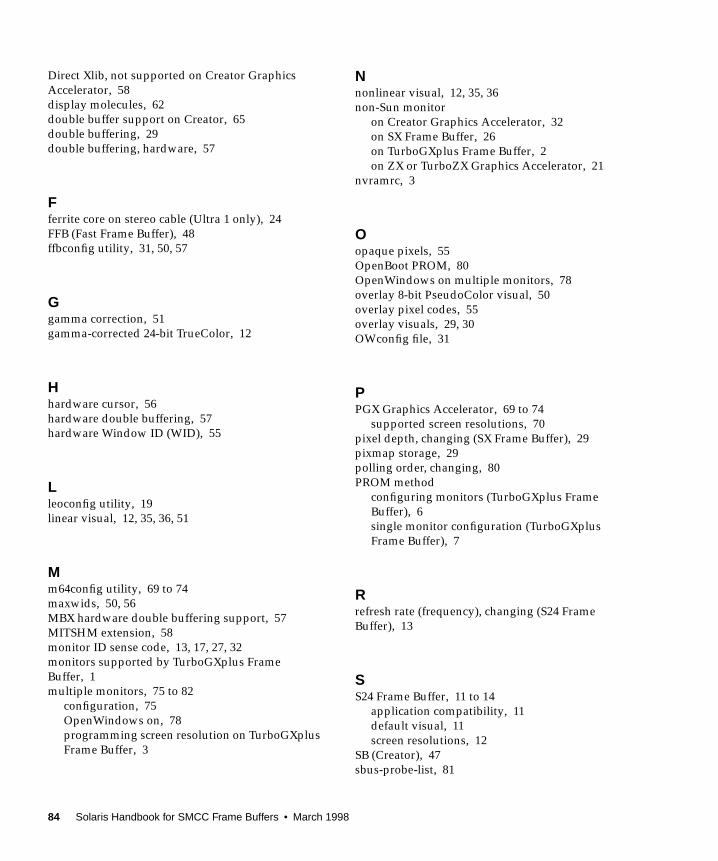
Direct Xlib, not supported on Creator Graphics
Accelerator, 58
display molecules, 62
double buffer support on Creator, 65
double buffering, 29
double buffering, hardware, 57
Fferrite core on stereo cable (Ultra 1 only), 24
FFB (Fast Frame Buffer), 48
ffbconfig utility, 31, 50, 57
Ggamma correction, 51
gamma-corrected 24-bit TrueColor, 12
Hhardware cursor, 56
hardware double buffering, 57
hardware Window ID (WID), 55
Lleoconfig utility, 19
linear visual, 12, 35, 36, 51
Mm64config utility, 69 to 74
maxwids, 50, 56
MBX hardware double buffering support, 57
MITSHM extension, 58
monitor ID sense code, 13, 17, 27, 32
monitors supported by TurboGXplus Frame
Buffer, 1
multiple monitors, 75 to 82
configuration, 75
OpenWindows on, 78
programming screen resolution on TurboGXplus
Frame Buffer, 3
Nnonlinear visual, 12, 35, 36
non-Sun monitor
on Creator Graphics Accelerator, 32
on SX Frame Buffer, 26
on TurboGXplus Frame Buffer, 2
on ZX or TurboZX Graphics Accelerator, 21
nvramrc, 3
Oopaque pixels, 55
OpenBoot PROM, 80
OpenWindows on multiple monitors, 78
overlay 8-bit PseudoColor visual, 50
overlay pixel codes, 55
overlay visuals, 29, 30
OWconfig file, 31
PPGX Graphics Accelerator, 69 to 74
supported screen resolutions, 70
pixel depth, changing (SX Frame Buffer), 29
pixmap storage, 29
polling order, changing, 80
PROM method
configuring monitors (TurboGXplus Frame
Buffer), 6
single monitor configuration (TurboGXplus
Frame Buffer), 7
Rrefresh rate (frequency), changing (S24 Frame
Buffer), 13
SS24 Frame Buffer, 11 to 14
application compatibility, 11
default visual, 11
screen resolutions, 12
SB (Creator), 47
sbus-probe-list, 81
84 Solaris Handbook for SMCC Frame Buffers • March 1998
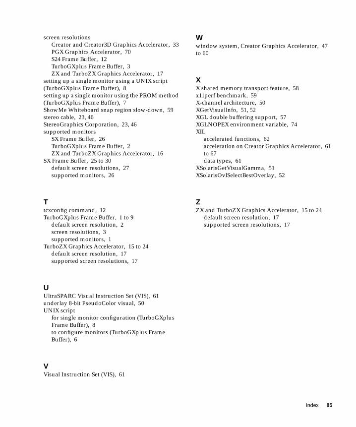
screen resolutions
Creator and Creator3D Graphics Accelerator, 33
PGX Graphics Accelerator, 70
S24 Frame Buffer, 12
TurboGXplus Frame Buffer, 3
ZX and TurboZX Graphics Accelerator, 17
setting up a single monitor using a UNIX script
(TurboGXplus Frame Buffer), 8
setting up a single monitor using the PROM method
(TurboGXplus Frame Buffer), 7
ShowMe Whiteboard snap region slow-down, 59
stereo cable, 23, 46
StereoGraphics Corporation, 23, 46
supported monitors
SX Frame Buffer, 26
TurboGXplus Frame Buffer, 2
ZX and TurboZX Graphics Accelerator, 16
SX Frame Buffer, 25 to 30
default screen resolutions, 27
supported monitors, 26
Ttcxconfig command, 12
TurboGXplus Frame Buffer, 1 to 9
default screen resolution, 2
screen resolutions, 3
supported monitors, 1
TurboZX Graphics Accelerator, 15 to 24
default screen resolution, 17
supported screen resolutions, 17
UUltraSPARC Visual Instruction Set (VIS), 61
underlay 8-bit PseudoColor visual, 50
UNIX script
for single monitor configuration (TurboGXplus
Frame Buffer), 8
to configure monitors (TurboGXplus Frame
Buffer), 6
VVisual Instruction Set (VIS), 61
Wwindow system, Creator Graphics Accelerator, 47
to 60
XX shared memory transport feature, 58
x11perf benchmark, 59
X-channel architecture, 50
XGetVisualInfo, 51, 52
XGL double buffering support, 57
XGLNOPEX environment variable, 74
XIL
accelerated functions, 62
acceleration on Creator Graphics Accelerator, 61
to 67
data types, 61
XSolarisGetVisualGamma, 51
XSolarisOvlSelectBestOverlay, 52
ZZX and TurboZX Graphics Accelerator, 15 to 24
default screen resolution, 17
supported screen resolutions, 17
Index 85

86 Solaris Handbook for SMCC Frame Buffers • March 1998


