00
SOME ENTRAINMENT PROPERTIES OF A TURBULENT
AXI-SYMMETRIC JET
By
George Naim Faris
Research Report No. 39 January 15, 1963
7I"l AP R 22 19 63C72l
EROPHYSICSMISS ISSI PPI ST AT E
UN I VE RS IT Y
SOME ENTRAINMENT PROPERTIES OF A TURBULENT
A)UI-SYMMETRIC JET
By
George Naim Faris
Research Report No. 39 January 15, 1963
Conducted ForI
OFFICE OF NAVAL RESEARCH
Under
CONTRACT NONR 978 (03)
By
The Aerophysics Department
Mississippi State University
Reproduction in whole or in part is permitted
for any purpose of the United States Government
ii
TABLE OF CONTENTS
CHAPTER PAGE
List of Figures ------------------------ iii
List of SLmbols ------------------------------------------- iv
I. Introduction --------------------------------------
II. Apparatus and Method -------------------------------- 3
III. Discussion ----------------------------------------- 4
The Structure of the jet --------------------------- 4
A New jet Profile Description--------------------- 4
Summation of Profile Behavior -------------------- 6
IV. Calculation of Entrainment Properties ------------------- 7
The Quantity of the Flow --------------------- 7
The Momentum Flux ---------------------------- 8
V. Conclusion ----------------------------------------- 11
REFERENCES --------------------------------------------- 12
iii
LIST OF FIGURES
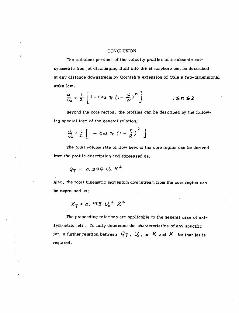
Figure 1 Descriptive layout of apparatus
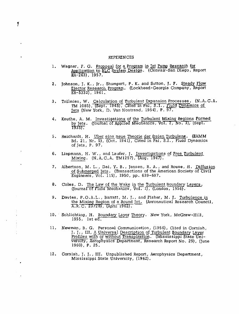
Figure 2 Experimental apparatus
Figure 3 Velocity profiles measured across the Jet
Figure 4 Schematic diagram of jet entrainment
Figure 5 Experimental downstream values of volume rate offlow and kinematic momentum
Figure 6 Comparison between theory and intermediate profilein the core region
Figure 7 Comparison between theoretical and experimentalprofiles in core region
Figure 8 The variation of "n " with distance downstream
Figure 9 Comparison between experimental profiles beyondcore region and theory
Figure 10 A comparison of theoretical jet profiles
Figure* 11 Comparison between theoretical and experimentalvolume rate of flow
Figure 12 Experimental downstream values of the jet radiusbeyond the core region
Figure 13 Comparison between theoretical and: experimentalvolume rate of flow beyond the core region
Figure 14 Comparison between theoretical and experimentalcenterline velocity
Figure 15 Comparison between theoretical and experimentalresults
iv
LIST OF SYMBOLS
D Nozzle diameter, ft
K Kinematic momentum, ft4/sec 2
M Momentum flux, lbs
n Exponent related to downstream distance, it n 5: 2z
Q Quantity of flow, ft 3/sec
r Distance measured in radial direction from jet centerline, ft
R Distance measured in radial direction from jet centerlineto the edge of the jet, ft
u Velocity within the turbulent area in the x-direction, ft/sec
U Maximum jet velocity, ft/sec
Ur Cole's wake function
41) Distance in radial direction from core edge, ft
W Distance in radial direction from core edge to edge of jet, ft
x Distance in downstream direction, ft
y Distance measured perpendicular to surface, ft
46 Wake function
S Distance in y-direction to edge of boundary layer, ft
P Density of air, lb-sec 2/ft 4
9 Angle, degrees
Subscripts
c Denotes core
e Denotes exit of nozzle (x = 0)
o Denotes centerline of jet
T Denotes total
INTRODUCTION
The jet mixing phenomena is frequently encountered in many engi-
neering problems such as jet pumps, ejectors, and combustion chambers.
The turbulent entrainment process of the jet forms the basis for many of
its applications. For example, the basis of a jet pump, or an ejector,
lies in the property of a moving jet of primary fluid to entrain a secondary
fluid and move it downstream. jet pumps, a primary example of turbulent
mixing, have been investigated as a power source for boundary layer con-
trol studies in aircraft (Ref. 1). Even with the low efficiency usually
associated with jet pumps, their use is found profitable because of their
small size, simplicity, and light weight. Ejectors, utilizing the same
entrainment principle, have found application in aircraft and ground effect
machines for thrust augmentation purposes (Ref. 2). For these and other
reasons the diffusion and entrainment properties Of free jets have been
the subject of extensive experimental and theoretical analysis.
Turbulent jet mixing of incompressible fluids was theoretically ana-
lyzed by Tollmien (Ref. 3) in 1926 by the use of Prandtl's mixing length
theory. In 1935 Kuethe (Ref. 4) developed an approximate method for com-
puting the profiles near the exit of a round jet discharging air into a medium
at rest. From experimental results, Reichardt (Ref. 5), in 1941, introduced
the constant exchange coefficient concept over the mixing zone. In 1947
Liepmann and Laufer (Ref. 6), using hot wire anemometer techniques for
measuring turbulent fluctuations, showed that neither the mixing length
nor the exchange coefficient is constant across the mixing region. Albertson,
et al (Ref. 7), in 1950, by presuming that the viscous effects have no in-
fluence on the mixing r'3gion concluded that the diffusion characteristics
2
of the flow are dynamically similar under all conditions. Consequently,
they used the Gaussian normal probability function to describe the ve-
locity profiles throughout the mixing region.
In the present investigation, experiments were performed to verify
the extension of Cole's Wake Law for two-dimensional boundary layers
(Ref. 8) to the case of axi-symmetric' free jet flows.
APPARATUS AND METHOD
The apparatus used in this investigation is shown schematically
in Figure (1).
The primary air flow was furnished by a two-horsepower portable
electric blower. A settling chamber, in which aluminum honeycomb was
placed, was connected to the blower and the fluid was finally released
into the atmosphere through a cylindrical nozzle one inch in diameter.
A powerstat, together with a constant voltage transformer, was utilized
to regulate the speed of the jet. The exit velocity of the fluid was main-
tained constant by preserving a constant differential static pressure be-
tween two pressure taps located on the circumferences of the settling
chamber and the cylindrical nozzle respectively. A Kollsman helicopter
airspeed indicator was used to measure velocities within the jet by means
of static and total head probes mounted on a three-directional rotary
table. The brass probes were connected to the airspeed indicator by
plastic tubing as shown in Figure (2). In addition, an aural stethoscope
was used to differentiate between laminar and turbulent flow regions.
The issuing jet was checked for symmetry by measuring the velocity
profiles across the jet, Figure (3). Measurements of the profiles were
taken at a differential static pressure equal to six inches of water which
corresponded to a centerline velocity of 176 ft/sec at the nozzle exit.
Velocities less than 16 ft/sec were not recorded due to possible in-
accuracies in the airspeed indicator. From the measured velocity pro-
fila-athe values for the total volume rate of flow and the total kinematic
momentum were graphically determined.
DISCUSSION
The Structure of the jet
The primary flow, except in the turbulent boundary layer at the
walls of the nozzle, emerges as a laminar jet with uniform velocity
which, beginning at the rim of the nozzle, becomes increasingly turb-
ulent downstream as the mixing region of primary and entrained flow
spreads inward. This turbulent region, surrounding the laminar core,
continues to expand until it merges at the jet centerline at some distance
downstream. In the present investigation this distance was 4.3 nozzle
diameters, which compares favorably with Keuthe's 4.44 nozzle diameters
(Ref. 4), and Davies' et. al. 4.35 nozzle diameters (Ref. 9). In addition
to spreading inward, the turbulent region spreads outward as shown in
Figure (4). The surrounding fluid is accelerated and the primary flow is
decelerated although the total kinematic momentum of primary and en-
trained fluid remains constant, Figure (5). The total volume rate of flow,
however, increases in the downstream direction (Ref. 10).
A New Let Profile Description
In order to obtain an accurate description of this entrainment pro-
cess, and extension has been made of an existing entrainment theory
now available in the study of turbulent boundary layers.
Immediately at the exit of the nozzle, the turbulent portion of the
flow can be approximately described by Cole's two-dimensional Wake
Law. Cole's wake function, W ( $ ) , can be approximated by the form
suggested by Newman (Ref. 11) as:
XZr
5
which, for two-dimensional wake profiles, may also be written as:
r Uf oOY (2)
or L -UUo (3)
where 2A - +[i oo ¥J
It has been recently suggested by Cornish (Ref. 12) that for axi-
symmetric Jet flows, A becomes a function of (I - where
I With this transformation, Cole's two-dimensional
Wake Law is extended to describe velocity profiles for Jet flows when
written in the following form:
[I - -, ý -
Neither Cole's two-dimensional Wake Law nor Cornish's axi-symmetric
form can describe the profiles in the core region since the flow is neither
purely two-dimensional nor fully developed jet flow, Figure (6). There-
fore, the following form has been suggested by Cornish to describe these
intermediate profiles:
u- =z-!-Cos Tr- n- -- 5: 2U0 ZL 1SI ~ / (5)
This relation becomes Cole's two-dimensional Wake Law when n = 1 and
will describe the fully developed jet profiles when n = 2. Profiles within
the core region are described with intermediate values of n. Because of
the experimental difficulty in measuring velocities near the periphery of
6
the jet, equation (5) is written in the following form:
U- -Ce r 05x T.. ,5" n:ý I • 2' (6)
UO,
For n 1, equation (6) will reduce to Cole's twc-dimensional Wake Law;
however, as n varies between 1 and 2, equation (6) describes the flow
within the core region. Velocity profiles have been measured experimentally
within the core region and have been compared to Cornish's theory in
Figure (7). The value of n for each profile varies with distance down-
stream of the nozzle. This variation of n as determined experimentally
is shown in Figure (8).
Beyond the core region, where profile similarity is preserved,
equation (6) will describe the fully developed jet profiles when n = 2
as shown in Figure (9). Equation (6) with n = 2 has been compared with
profiles developed by Schlichting and Tollmien in Figure (10).
Summation of Profile Behavior
From the preceding analysis the behavior of the profiles can be de-
duced. In the mixing region immediately downstream of the nozzle, the
turbulent portions of the velocity profiles are nearly two-dimensional.
As the distance from the nozzle is increased, these profiles gradually
change until at the end of the laminar core the turbulent profiles become
fully developed axi-symmetric jet flow.
CALCULATION OF ENTRAINMENT PROPERTIES
The Quantit, of the Flow
At any distance, x, downstream the total volume rate of flow can
be expressed as:
QT u dr do (7)
The boundary conditions are:
Core Region; 0 9- r. a= Uo= Ue = const. (8)
Wake Region; rct- rSý (Je__ 2_ 0 (9)
R- rc = W and r- r•. = a
Substituting equation (5) in equation (7) and integrating, using the series
expansion for the cosine function, the following general equation for the
volume rate of flow is obtained:
QT Ue+rMwzUa/ z+)r2W7Io -
'Y==
+ Z )!.n + 7lrrcWL/ofh-L(F.)!(zn fl)
Equation (10) is compared with the data in Figure (11). In the profile
similarity region where rr =0 and 1, = 2. , equation (10 will reduce to
Q T = 0. . 74 U,, R()
8
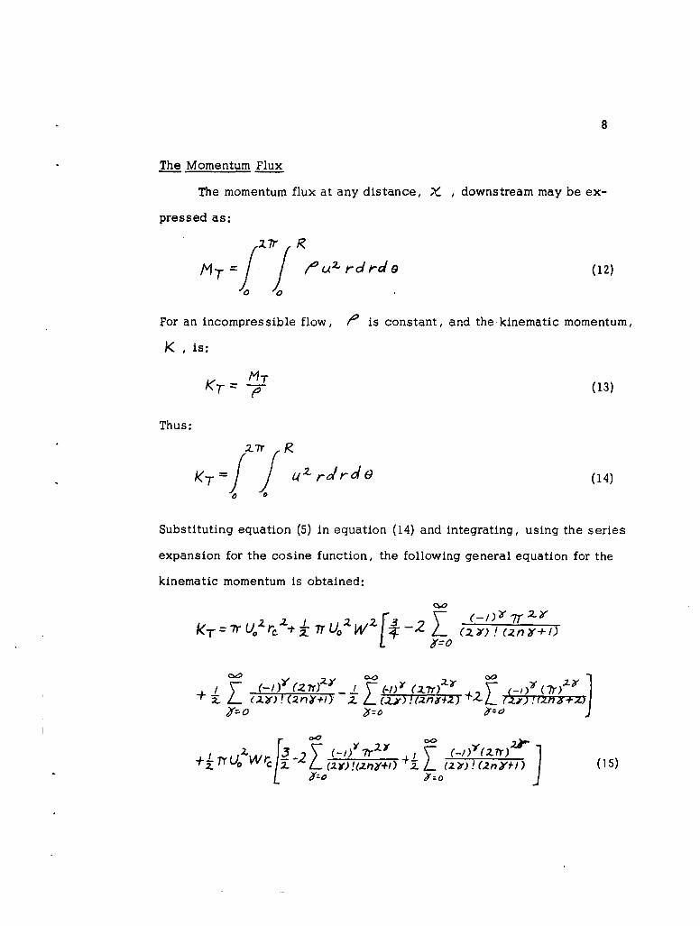
The Momentum Flux
The momentum flux at any distance, X , downstream may be ex-
pressed as:
MT= !, ý 7r 1 /u42 rdede (12)
0
For an incompressible flow, / 0 is constant, and the kinematic momentum,
K , is:
KT - T (13)
Thus:
KdT Z 4 r/rd4 (14)
of 0
Substituting equation (5) in equation (14) and integrating, using the series
expansion for the cosine function, the following general equation for the
kinematic momentum is obtained:
kT Uo7fZ•. oW f-2 Z (z) ! (.znY+i)
- 21 ( ,2. ') !(2 fl0 +l) H ) Y (2 . 7r) • ) "4-2...V)
+ I
++-T LUo wr- -2 4 (15)zl)(z¥! t. (2.,Y)! (2n•÷1) (5ey- #=
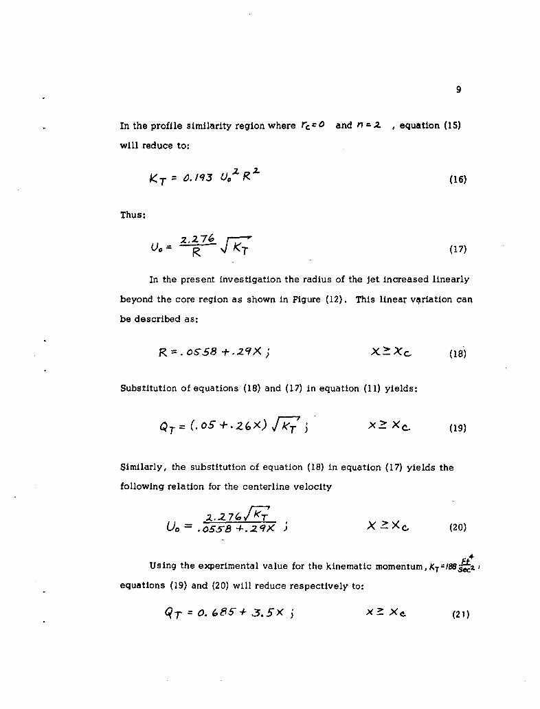
9
In the profile similarity region where rc and n -.z , equation (15)
will reduce to:
='/13 U. 2 (16)
Thus:
U"-27( '• (17)
In the present investigation the radius of the jet increased linearly
beyond the core region as shown in Figure (12). This linear variation can
be described as:
R=. 058+.9X. X Xc. (18)
Substitution of equations (18) and (17) in equation (11) yields:
05 (.o -+.Z X) , 7T j X xc (19)
Similarly, the substitution of equation (18) in equation (17) yields the
following relation for the centerline velocity
=.Z. 2 ..6//<T X a-xc. (20)
.,4
Using the experimental value for the kinematic momentum, KT=186.
equations (19) and (20) will reduce respectively to:
q" = 0. 685-+ 3.5X X >_ xe_ (21)
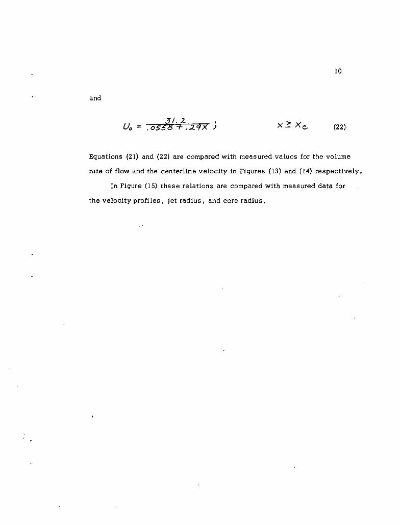
10
and
00 31.058 +.2?X x C, (22)
Equations (21) and (22) are compared with measured values for the volume
rate of flow and the centerline velocity in Figures (13) and (14) respectively.
In Figure (15) these relations are compared with measured data for
the velocity profiles, jet radius, and core radius.
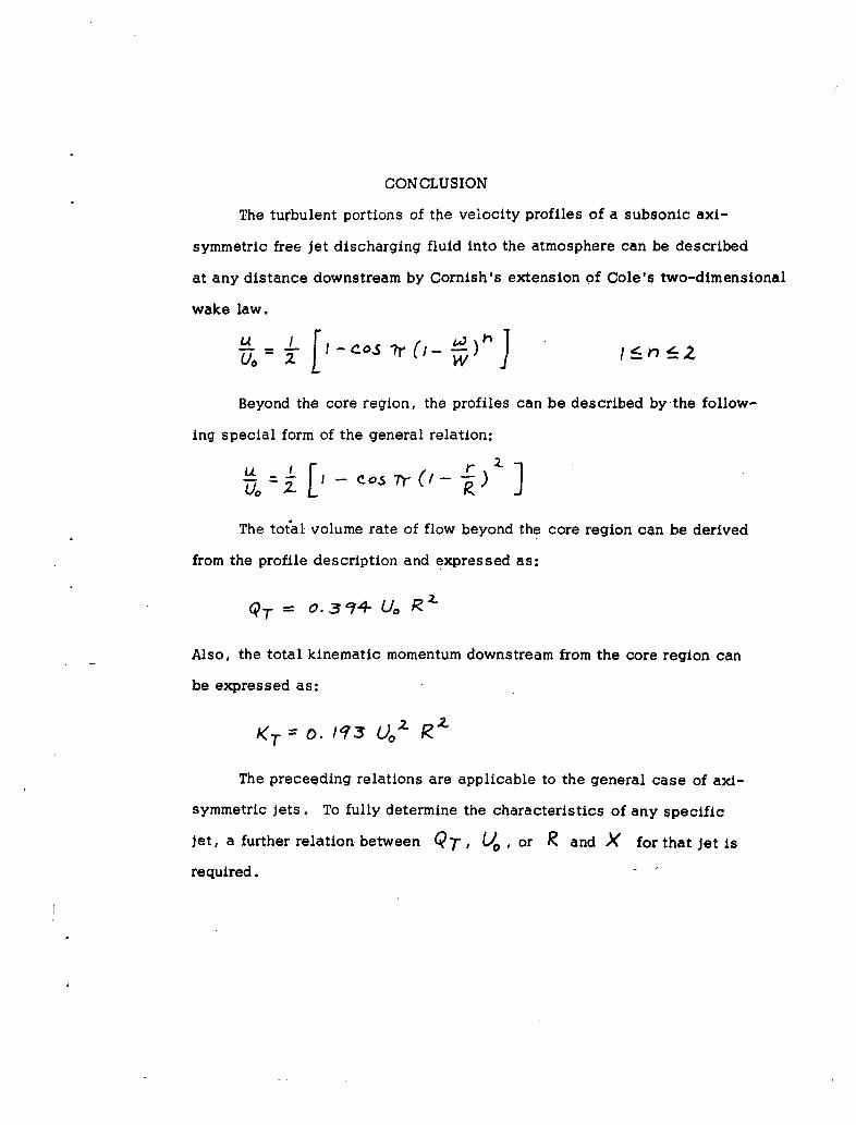
CONCLUSION
The turbulent portions of the velocity profiles of a subsonic axi-
symmetric free jet discharging fluid into the atmosphere can be described
at any distance downstream by Cornish's extension of Cole's two-dimensional
wake law.
Uo- I-co's 7,(i- ri) •Z
Beyond the core region, the profiles can be described by the follow-
ing special form of the general relation:
U L C -57ros (/- ) 3The total volume rate of flow beyond the core region can be derived
from the profile description and expressed as:
QT 0-314 U-, R'
Also, the total kinematic momentum downstream from the core region can
be expressed as:
KT =. 0 93 U)0 ?2Z
The preceeding relations are applicable to the general case of axi-
symmetric jets. To fully determine the characteristics of any specific
jet, a further relation between QT, Uo, or R and X for that jet is
required.
CON CLUSION
The turbulent portions of the velocity profiles of a subsonic axi-
symmetric free jet discharging fluid into the atmosphere can be described
at any distance downstream by Cornish's extension of Cole's two-dimensional
wake law.
U. I I Co'.s -)
Beyond the core region, the profiles can be described by the follow-
ing special form of the general relation:
The total volume rate of flow beyond the core region can be derived
from the profile description and expressed as:
QT 394 Uo RL
Also, the total kinematic momentum downstream from the core region can
be expressed as:
KT . 11• 3 £40
The preceeding relations are applicable to the general case of axi-
symmetric jets. To fully determine the characteristics of any specific
jet, a further relation between QT, , or R and X for that Jet is
required.
REFERENCES
1. Wagner, F. G. Proposal for a Progra in jet Pump Research forApplication to BLC System Design. (Convair-San Diego, ReportZA-263), 1957.
2. Johnson, J. K., Jr., Shumpert, P. K. and Sutton, J. F. Steady FlowEjector Research Program. (Lockheed-Georgia Company, ReportER-533.2), 1961.
3. Tollmien, W. Calculation of Turbulent Expansion Processes. (N.A.C.A.TM 1085), (Sept. 1945)" Cited in P~alS:.., Fluid Dynamics ofTets (New York, D. Van Nostrand, 1954), P. 97.
4. Keuthe, A. M. Investigations of the Turbulent Mixing Regions Formedby Jets. (Journal of ApplieU M -chanics, Vol.2,No.TT,(Sept.
5. Reichardt, H. Uber eine neue Theorie der freien Turbulenz. (ZAMMBd. 21, Nr. 5), (Oct. 1941), Cited in Pai, S.I., Fluid Dynamicsof jets, P. 97.
6. Liepmann, H. W., and Laufer, J. Investigations of Free TurbulentMixing. (N.A.C.A. TM1257), (Aug. 1947).
7. Albertson, M. L., Dai, Y. B., Jensen, R. A., and Rouse, H. Diffusionof Submerged Tets. (Transactions of the American Society of CivilEngineers, Vol. 115), 1950, pp. 639-697.
8. Coles, D. The Law of the Wake in the Turbulent Boundary Layers.(Journal-TliTd--lec--hanics, Vol--1), (London, 1956).
9. Davies, P.O.A.L., Barratt, M. J., and Fisher, M. J. Turbulence inthe Mixing Region of a Round Jet. (Aeronautical Research Council,
10. Schlichting, H. Boundary Layer Theory. New York, McGraw-Hill,1955. lst ed.
11. Newman, B. G. Personal Communication, (1956), Cited in Cornish,J. J., III, A Universal Description of Turbulent Boundary LayerProfiles with or without Transpiration. (Mississippi State Uni-versity, AeropTiysics Department, Research Report No. 29), (June1960), P. 25.
12. Cornish, J. J., III. Unpublished Report, Aerophysics Department,Mississippi State University, (1962).
Figure 1
-14
STJ
k
N'.4
Figure 2
IZI-
. KL x0U
Figure 3
0
-ID
0
000
0
60O
00
'.4A
Fgure 4
k
�4J
ki'4'
k
'ad
t4�% I'
U 14J �I *4J
1% I
'ad I'
UI'
Figure 5
0 0
0'0
0 13
0
It -
000
0 0U
00
Figure 6
:-k'KS
-e
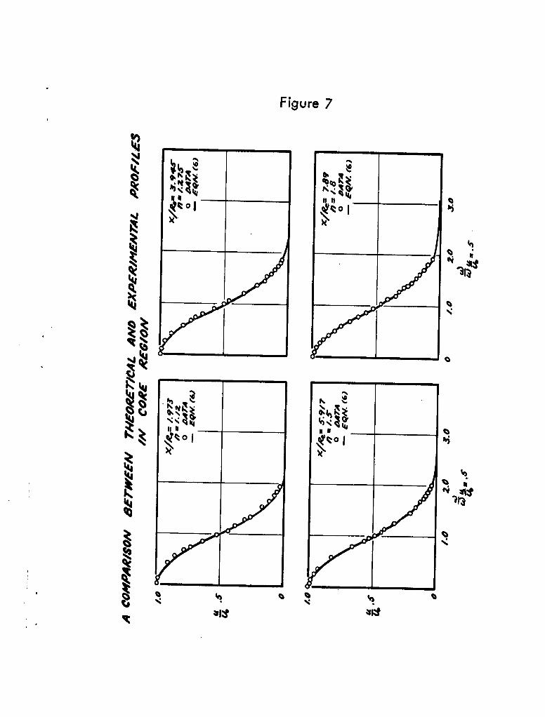
Figure 7
N Z
Nili
4'4% "
'J
'Ira
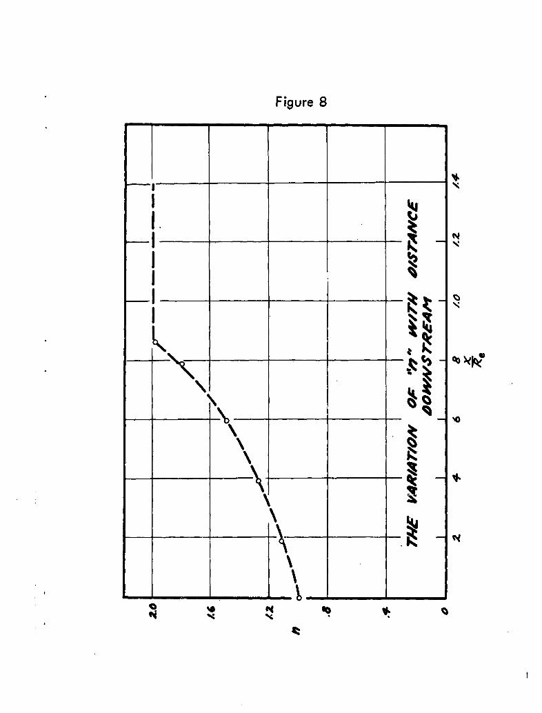
Figure 8
Sm
X
I
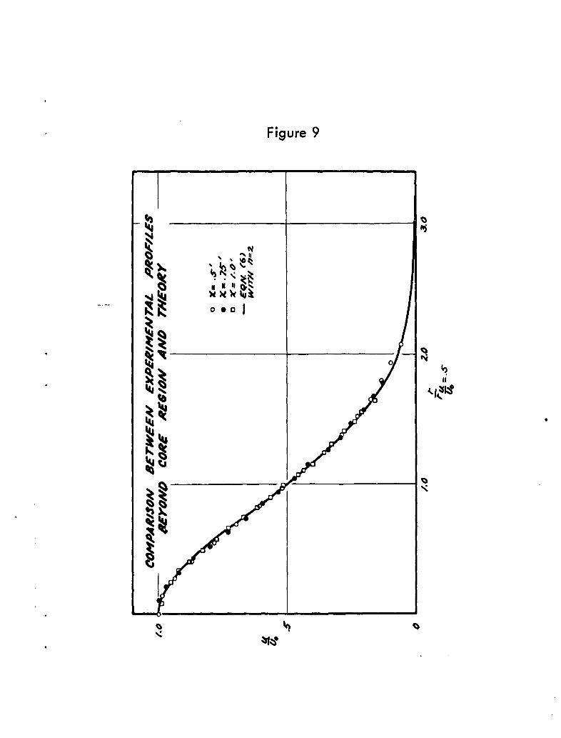
Figure 9
'4h4
103
'4
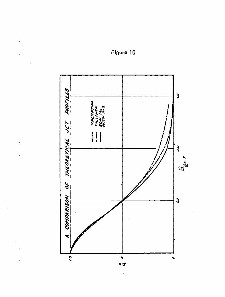
Figure 10
-N
IKI
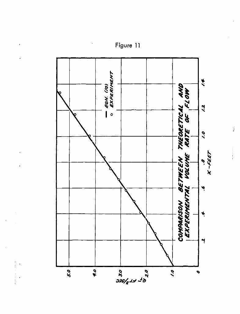
Figure I1I
FFk
1_ __ 54t
_ _ _ _ _ _ _ _~s L4
_ _ _
It
'4041 _ _ _
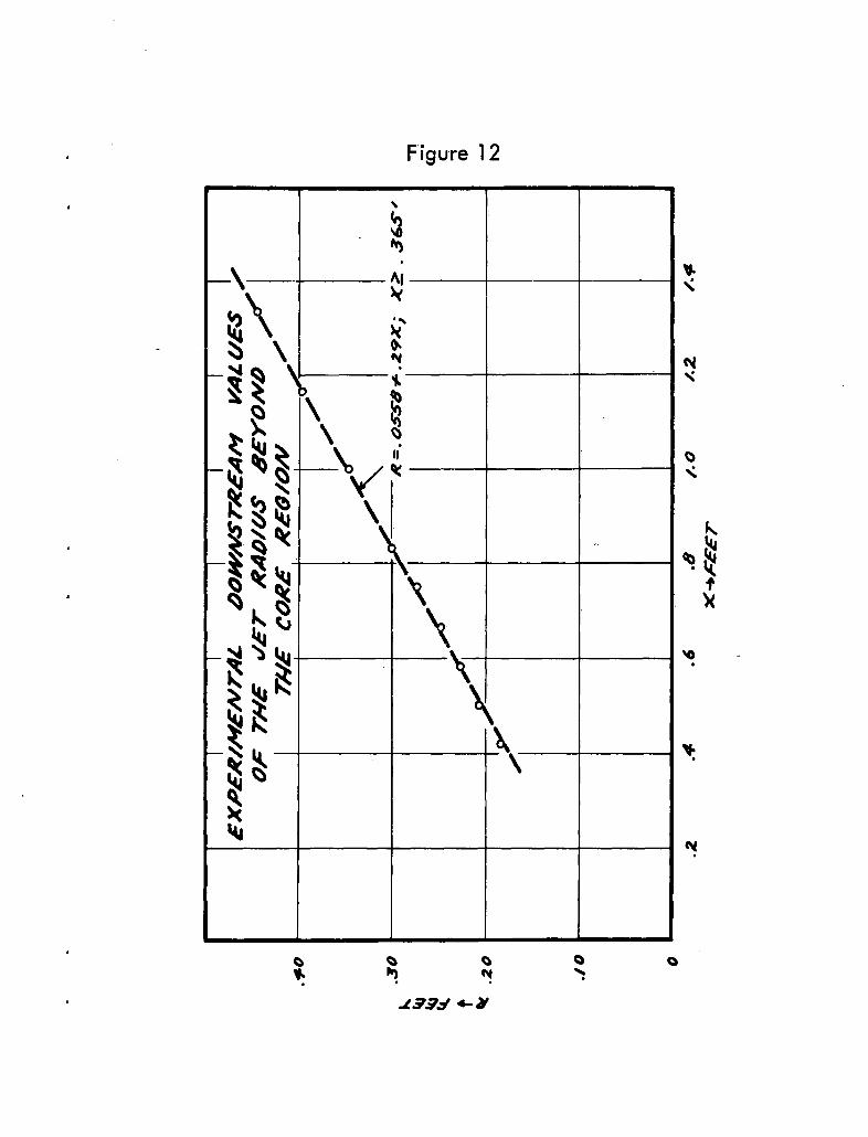
Fig ure 12
I4J
.79d t
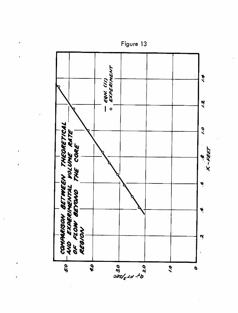
Figure 13
t~4
0'
zuI
leta
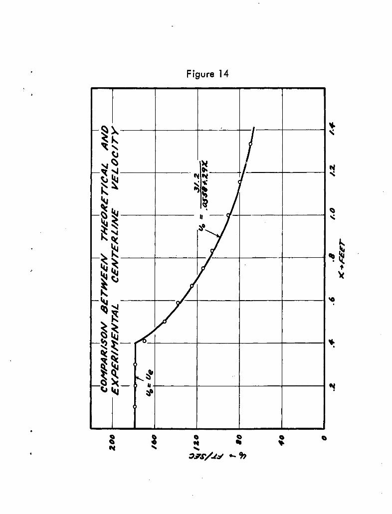
Figure 14
-4-
t4~
~JR N ol0
II--
* ~4J _ _ Ill
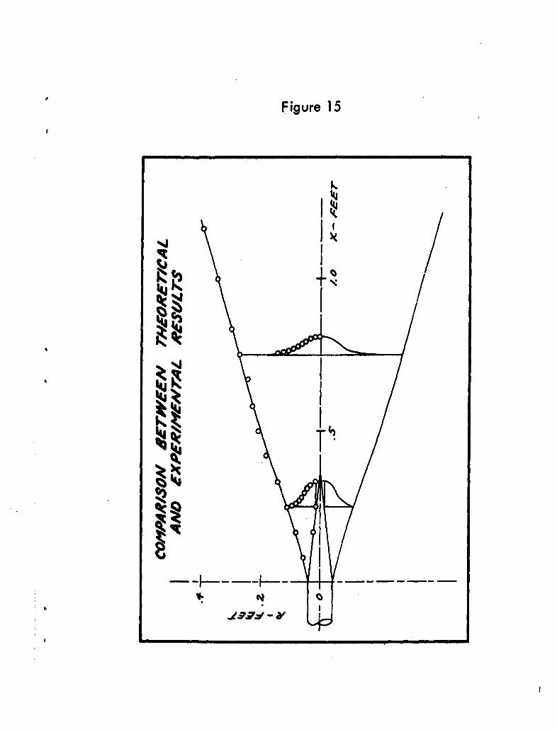
Figure 15
k
iz
x
1J ,


![AXI Protocol Checker v1 - Xilinx · The AXI Protocol Checker core monitors AXI interfaces. When attached to an interface, it ... See ARM AMBA® AXI Protocol v2.0 [Ref 1]. Performance](https://cdn.vdocument.in/doc/165x107/5b158bc17f8b9ac7128d1298/axi-protocol-checker-v1-xilinx-the-axi-protocol-checker-core-monitors-axi.jpg)