
J
f/
/fJ
z f
Space Transfer Concepts and Analysisfor Exploration Missions
Contract NAS8-37857
Final ReportTask Directive 5
March 1991
Boeing Defense & Space GroupAdvanced Civil Space Systems
Huntsville, Alabama
,aj.- _{_17:;
D615.10031.1
https://ntrs.nasa.gov/search.jsp?R=19910020861 2020-05-17T14:45:30+00:00Z

-._j
r._j

Abstract
The current study is the second phase of a broad-scoped and systematic study of space
transfer concepts for human Lunar and Mars missions. The one month Technical Dir_tive
5 is a short follow-on to the initial contract. During this period, relevant space
transportation studies were initiated to lead to further detailed activities in the following
study period.
Key Words
Architeca_
Habitats
Life Cycle CostManifesting
Missions (Lunar and Mars)Space Propulsion
Space Vehicle ConceptsTrajectories
D615-10031-1 1

Abstract
TABLE OF CONTENTS
PAGE
1
_4
Table of Contents 2
. INTRODUCTION 6
Q VEHICLE INTEGRATION
2.1 Introduction 7
2.2 Subsystem Overview
2.3 Propellant Iced System/Major Elements Description
2.4 Propulsion System Schematics 11
2.5 Fluid Lines II
2.6 SupportingDam 11
2.6.1 PropeUant Line Size Determination Procedure 11
2.6.2 Tank PressurizationSystem Analysis 12
2.6.3 AUowablc Line Pressure Drop Results 14
2.6.4 BoiloffLoss Estimate for Dropping Multi-Use Tank Pressure 15
2.6.5 Summary and Conclusion 16
D615-10031-1 2

/J
. AEROBRAKE INTEGRATION 23
3.1
3.1.1
Properties and Processing of Intermetallic Titanium Aluminides
Abstract
23
23
3.1.2 Introduction 23
3.1.3 Alloying Elements and Their Effects 24
3.1.4 Properties of Titanium Aluminide Intermetallics 24
3.1.5 Fabrication and Processing Techniques 26
3.1.6 Summary and Conclusions 27
3.2
.
Aerobrake Structural Integration
Assembly Operations and ETO Vehicle Size Requirements
28
38
4.1 Gantry-Rail Platform 38
4.2 Modified/-Beam with Lazy Susan 39
4.3 Common Hab and Assembler/Servicer 39
4.4 Tethered Robotic Assembly Platform 40
4.5 Assembly Ball Platform Concept 41
4.6 H-O Assembly Platform Concept 41
4.7 General Requirements 41
. CREW 50
D615-10031-1 3
. FLIGHT DYNAMICS 53
. ARCHITECTURE ASSESSMENT, PROGRAMMATICS
ANALYSIS, AND TECHNOL£X3Y ADVANCEMENT 56
7.1 Beam Power Electric Orbit Transfer Vehicle 56
7.1.1 The Case for Power Beaming 56
7.1.2 Microwave vs. Laser 56
7.I.3 InclinedOrbits 57
7.1.4
7.1.5
Beam EOTV Simulator
The "Unwrap" Condition
58
58
7.1.6 Initial Simulation Results 59
7.2 Earth Orbit Return From Mars Transfer 59
7.2.1 Return Geometry 59
7.2.2 Recovery Scenario 59
7.3 Alternate Lunar Mission 6O
7.3.1 Campsite 6O
7.3.2 Crew Mission 60
7.3.3 Launcher Concept 6O
7.3.4 Science Candidates 61
7.4 Power Beaming Presentation 61
v
D615-10031-1 4
.SUPPORT TO MSFC SEI ACTIVITIES 65
8.1 Minimum-Sized Lunar Campsite Analysis 65
APPENDICES
APPENDIX A
POWER BEAMING 67
APPENDIX B
MINIMUM-SIZED LUNAR CAMPSITE ANALYSIS 81
D615-10031-1 5
• INTRODUCTION
The first phase of the technical work carried out in the "Space Transfer Concepts and
Analysis for Exploration Missions" contract performed by Boeing Aerospace and
Engineering under Contract NAS 8-37857 was completed January 1991. In the month
of February, Technical Directive 5 was provided to BA&E for additional tasks relating
to space exploration studies. The activities conducted during this short duration
Technical Directive are described in the text that follows. This initial work is a prelude
for the work to follow on the remaining portion of the contract.
The tasks addressed include:
Vehicle Integration
Aerobrake Integration Analysis
Assembly Operations and ETO Vehicle Size Requirements
Transportation Crew Module and Habitat Update
Radiation Analysis
Flight Dynamics Support
Architecture Assessment, Programmatic Analysis and
Technology Advancement Priorities and Recommendations
Support to MSFC SEI Activities
. i
!
't
D615-10031-1 6

/ j
/
2. VEHICLE INTEGRATION
2.1 Introduction
The Space Transfer Concepts and Analysis for Exploration Missions (STCAEM) Phase 1
study identified the Nuclear Thermal Rocket (NTR) as the most versatile high-performance
candidate for Mars missions for reasonable SEI program scales. The STCAEM Phase 2
Vehicle Integration task, begun in Technical Directive 5 (TD5), is investigating the
integration issues of the NTR propulsion system in sufficient detail to determine system
operations protocols, determine subsystem mass with greater fidelity, identify areas
requiring focused technology development, and develop specific requirements for vehicle
assembly, processing, inspection, verification, use and refurbishment.
SpeciflcaUy, Phase 2 has targeted four areas of work in detailing the NTR propulsion
subsystem:
a. Discussion of issues, options, selections and rationales for the NTR propulsion
subsystem.
b. Schematics and definition of interfaces for the engine/reactor, tanks, propellant feed
lines, pressurization subsystem, and power/data/control lines.
c. Sizing of fluid lines and elecaieal lines.
d. Implications for vehicle test, pre-flight operations ('LEO integration), and in-flight
operations.
TD5 has accomplished the initial portions of work in the first three areas listed. Most effort
has focused on formulating the investigation strategy, developing the calculation
methodologies, and exercising bounded-problem cases pertinent to the NTR design. The
propulsion subsystem involves a complex set of interrelated design issues, and the TD5
effort represents the initial "tip" of that large iceberg. A summary of the NTR propulsion
system definition accomplished so far is followed by technical backup material on line
sizing, the design of the pressurization subsystem, and schematics.
t
' D615-10031-1 7'

2.2 Subsystem Overview
Solid-core nuclear rocket propellant feed systems are essentially the same as for the I-I2
portion of a I.,H2/LO2 chemical engine. The propellant flowing from the pump enters the
nozzle, flows upward through the neutron reflector surrounding the reactor core, cooling
both the reflector and the control drums contained within it, and through a neutron and
gamma ray shield placed at the upper end of the reactor assembly to limit the radiation-
heating of propellant in the tank. The propellant flows downward through the reactor fuel
element cooling passages,reaching thenozzle inletdesigntemperann'ebeforeexitingthe
nozzleplenum chamber priortobeing dischargedthrough theexhaustnozzle. A portionof
the propellant flow is bled off from thischamber and cooled to an acceptable inlet
temperatureforthe pump driveturbine.This coolingisaccomplished primarilyby mixing
the heated material with cold fluids. A small amount of gas is also drawn from the
turbopump outletforpressurizationof thepropellanttanks.
The propellant fecxl system consists of one or more turbopumps, a propellant source, and a
system of pipes and valves, including control valves. These components differ from similar
components found in liquid chemical rockets only in the modifications required to allow
them to survive and function properly in the reactor radiation environment. Of typical and
primary concern inthisrespectarcvalve seats,seals,bearinglubricants,and rollingcontact
bearing retainers. In cryogenic chemical rockets,these are usually made of organic
martials thatare subjecttoseveredamage under neutronand gamma bombardment. Also,
valve actuatorsin most chemical rocket systems are of the hydraulictype and the fluids
involved would change in a nuclearrocket eitherbecoming highly viscous or evolving
gases under the action of high-energy radiation.Consequently, pneumatically- or
electrically-operateddevicesmust be used inthe nuclearrocketengines.Radiationheating,
though itmust be consideredinthe design,does not pose a significantproblem in.most of
thecomponents of thissystem due to thehigh flow ratesof cryogenichydrogen incontact
with thecomponents.
The principalsubassembly of thepropellantfeedsystem isthe turbopump and theprimary
factorsinfluencingthe design of thisunitare reliability,efficiency,and weight. Pump
efficiency is affected not only by the particular design selected, but also by the net positive
suction head (NPSI-I); i.e., the difference (available at the pump inlet) between the total
absolute pressure and the fluid vapor pressure. This effect is particularly apparent if the
NPSH is low.
T
D615-10031-1 8
It f
j/"
/J
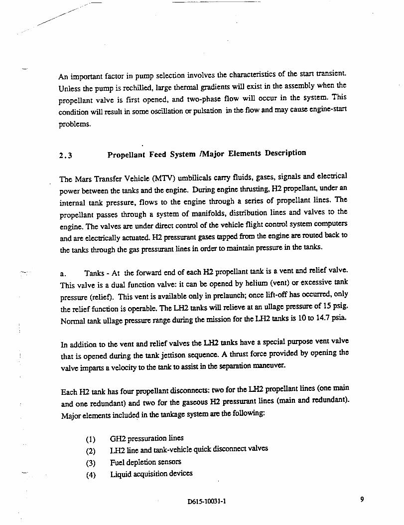
An important factor in pump selection involves the characteristics of the start transient.
Unless the pump is rechilled, large thermal gradients will exist in the assembly when the
propellant valve is first opened, and two-phase flow will occur in the system. This
condition will result in some oscillation or pulsation in the flow and may cause engine-start
problems.
2.3 Propellant Feed System /Major Elements Description
The Mars Transfer Vehicle (MTV) umbilicals carry fluids, gases, signals and electrical
power between the tanks and the engine. During engine thrusting, H2 propellant, under an
internal tank pressure, flows to the engine through a series of propellant lines. The
propellant passes through a system of manifolds, distribution lines and valves to the
engine. The valves are under direct control of the vehicle flight control system computers
and are electrically actuated. H2 pressurant gases tapped from the engine are routed back to
the tanks through the gas pressurant lines in order to maintain pressure in the tanks.
a. Tanks - At the forward end of each H2 propellant tank is a vent and relief valve.
This valve is a dual function valve: it can be opened by helium (vent) or excessive tank
pressure (relief). This vent is available only in prelaunch; once lift-off has occurred, only
the relief function is operable. The LI-I2 tanks will relieve at an ullage pressure of 15 psig.
Normal tank ullage pressure range during the mission for the LH2 tanks is l0 to 14.7 psia.
In addition to the vent and relief valves the LH2 tanks have a special purpose vent valve
that is opened during the tank jettison sequence. A thrust force provided by opening the
valve imparts a velocity to the tank to assist in the separation maneuver.
Each H2 tank has four propellant disconnects: two for the LH2 propellant lines (one main
and one redundant) and two for the gaseous H2 pressurant lines (main and redundant).
Major elements included in the tankage system are the following:
(1)
(2)
(3)
(4)
GH2 pressuration lines
].2L2 line and tank-vehicle quick disconnect valves
Fuel depletion sensors
Liquid acquisition devices
D615-I0031-1 9

(5)
(6)
(7)
(8)
(9)
(I0)
Antivortexbafflenearliquidacquisitiondevice
Pressure and temperaturesensors
Tank loadingsensorsLH2 ullagepressuresensors
SpecialpurposevalvesMLI and vapor cooled shields
Meteor debrisshield
b. Helium Tank Pressurant System (transient) - Initial (start transient) tank
pressurization is provided by the high pressure helium gas system. Helium gas at 3000-
5000 psia is stored in titanium liner/composite overwrap high pressure tanks. When needed
for tank pressurization, the gaseous helium passes through the pressure regulation,
valveing, and distribution line systems to the H2 tanks to provide tank pressurization until
H2 gas from the engine can be tapped from the turbopumps and routed to the tanks through
the H2 gas pressurant line system.
c. Gaseous H2 Tank Pressurant System (steady state) - Internal pressure in the H2
tanks is maintained by the gaseous H2 for the duration of the propulsive burn.
d. Propellant Line, Valve and Turbopump Cooldown - Approximately 1 hr before
engine start, LH2 propellant is released into and through the propellant delivery system.
This propellantchillsdown allthe LH2 lines,manifolds and valvesbetween the tank and
the engine turbopumps so that the path is bee of GH2 bubbles and is at the proper
temperature forengine start.
e. Post Burn Propellant Tank Jettison - The interface between the individual tank LH2
propellant lines and the vehicle LH2 manifold is a self-sealing quick disconnect. The
interface between the tank GH2 pressurant line and the GH2 manifold is also a self-sealing
quick disconnect. The tank separation maneuver is preceded by valve closure to isolate the
empty tank from the rest of the propellant line system. The tank release mechanism is then
activated, and the tanks are pushed away from the vehicle mechanically. The special
purpose vent valves supplement the separation release mechanism with a small thrust force
driven by tank internal pressure.
f. Tank Attachment and Disconnect - Tank disconnect occurs on the tank side of the
LH2 line manifold. Self sealing liquid and gas quick disconnects are provided to allow the
complete tankage system to be jettisoned after a propulsive burn and also to allow the
)
v
D615-1003 I-1 I0

j
j_
_J
/
reattachment of a new fully loaded tankage system in Earth orbit for reuse on another
mission. In addition to the liquid propellant and gaseous pressurant disconnects, power
and data cable disconnects are also provided for.
g. System Verification Tests - It is desirable to have the capability to conduct a
complete checkout test verifying the tankage system and all its subsystems fully loaded on
the launch vehicle while on the pad before launch. After launch and attachment to the
orbiting NTR vehicle, LH2 propellant is transfered to the tank to top off the LH2 level in
the tank. A complete tankage system and propellant flow test is also conducted after vehicle
assembly in orbit for identification and possible replacement of suspect subsystems.
2.4 Propulsion System Schematics
Some schematic diagrams for the hydrogen propellent flow, three turbopurnp engine
configuration, hydrogen and helium gas pressurant flow and hydrogen tank are illustrated
in Figures 2-1 to 2-4.
2.5 Fluid Lines
Different sections of the piping would be exposed to different combinations of cryogenic
temperature, nuclear radiation, and chemical attack by hydrogen. Materials most suitable
for piping are special alloys of aluminum, titanium, and stainless steel. Stainless steel was
chosen for application as the H2 propellant line and the gaseous H2 pressurant lines.
The fact that hydrogen can be used for auxiliary as well as for primary needs implies that
two systems of piping are required. The primary piping is concerned with large flow rates,
intermittent flow, and phase transition from LH2 to GI-I2. The secondary piping is
concerned with low flow rates, continuous flow, and all GH2. These features are
summarized in the Figure 2-5.
2.6 Supporting Data
2.6.1 Propellant Line Size Determination Procedure
The procedure to determine the propellant line size is indicated below.
D615-10031-1 11
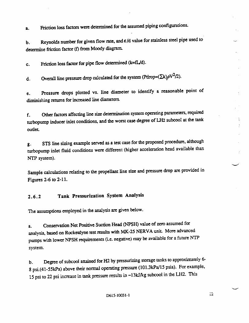
a. Friction loss factors were detem_ed for the assumed piping configurations.
b. Reynolds number for given flow rate, and e/d value for stainless steel pipe used to
determine frictionfactor(f)from Moody diagram.
c. Friction loss factor for pipe flow determined (k-fldd).
d. Overalllinepressuredrop calculatedforthesystem (Pdrop=G_.,k)pV2/2).
e. Pressure drops plotted vs. line diameter to identify a reasonable point of
diminishing returns for increased line diameters.
f. Other factorsaffectinglinesizedeterminationsystem operatingparameters,required
mrbopump inducerinletconditions,and the worst case degree of LH2 subcool at the tank
outleL
g. STS linesizingexample servedas a testcaseforthe proposed procedure,although
turbopump inletfluidconditionswere different(higheraccelerationhead availablethan
NTP system).
Sample ca/cu/ations relating to the propel/ant line size and pressure drop arc provided in
Figures 2-6 to 2-11.
2.6.2 Tank Pressurization System Analysis
The assumptions employed intheanalysisarc given below.
a. ConservationNet PositiveSuctionHead (NPSH) value of zeroassumed for
analysis, based on Rocketdyne test results with MK-25 NERVA unit. More advanced
pumps with Iowcr NPSH requirements (i.e. negative) may be available for a future NTP
system.
b. Degree of subcool attainedforH2 by pressurizingstoragetankstoapproximately 6-
8 psi.(41-55kPa)above theirnormal operatingpressure(101.3kPa/15 psia).For example,
15 psito 22 psiincreaseintankpressureresultsin-131d/kg subcool intheLH2. This
D615-10031-1 ;2

J
degree of subcool must bc below theenergy added tothefluidby environmental and
pressuram gas heating, and propellant delivery line losses.
c. Environmental heating determined from CRYSTORE boiloff code. Preliminary
analysis results show that aft tank radiation heating effects are small in comparison to
environmental heating(Radiationheating<5% ofenvironmentalheatingduringbarn time,
assuming allneutronsadsorbed atan average energy levelof 2.5McV).
d. Pressurantgas heatingassumed toconsistmainly of freeconvection (duringburn
only),and gas conduction.
e. Deliverysystem propellantheatingdetcm_ed fi'omenvironmentalheating(whilein
deliverysystem),and linelosses.Thisheatingnot a largedriverinthe levelof subcool
loss.IAnc pressurelosses,and thereforelinesizes,can bc determined based on tank
pressuresand NPSH requirements.
f. Pressurantgas requirementstoo high forhelium pressurization.Helium utilizedfor
initialtankpressurization,linechilldown,and engin.cstart-up(first30 seconds of bum).
Hydrogen bleedfrom turbopump utilizedforsteady-stateoperation.
g. Propellant heating after initial over-pressurization mainly due to f_ee and forced
convection at the liquid surface from the pressurant gas (helium and hydrogen). Forced
convection considerrxl small ff suitable diffuser used for pressumnt gas inlet.
h. Free convection heat transfer is the largest single conuibutor to the subcooled
propellant, but it only occurs during bum periods (~ I hour for TMI).
(1) A preliminaryassessme.ntof allowableheatleakallowed inorderforthe
fluidtoremain subcooledfortheentiredurationofthe 3 TMI burns (completed
over approx. 24 hours).
(2) Results showed that the cumulative heating on the TMI propellant would
remain below allowablelimitsffthehight_mperamm turbinebleedgas isboth
throttled(toreduce pressure),and cooled by thepump exitfluidflow below -I00
K beforebeing injectedintothetank.
D615-10031-1 13 ,

i.
j.
k.
2.6.3
(3) The effects of helium "blanketing" of the fluid were not considered so the
allowable inlet gas texture may be higher.
The initial pressurization system (helium) can be one of two major types:
(1) Internal storage systems require smaller tank sizes, due to the higher He gas
density at 20 FL versus about 180-200 K for external systems. Composite tanks
may not be applicable for this low temperature. The higher storage density is
somewhat offset by the higher density of the helium in the ullage.
(2). External storage systems require higher tankage mass, and also requh-¢
significantly less gas for ullage pressurization. Significant amounts of heat are
transferred to the LH2 from the warmer (180-200 K) helium.
Helium system mass estimates:
(1)
(2)
External System - He--44 kg.
Tanks--250 kg.
Total=-294 kg. (per TMI tank)
Internal System - He--160 kg.
Tanks--220 kg.
Totals-380 kg. (per TMI tank)
Note: High temperature gas
can reduce subcool level by as
much as 0.7 kJ/kg. (-5%).
Propellant line chilldown fluid requirements:
(1) Line Diameter - 10" (25.4 cm.); Length - 70 m.; thickness - 0.4 ram. H2
mass vaporized to bring fluid lines down to 20 K - 225 kg. (This vaporized fluid
can be expanded through the engine to provide a measure of thrust).
Allowable Line Pressure Drop Results
i
J
Some results based upon the allowable line pressure drop are given. (See Figure 2.12)
a. Pressure drop curves utilized to identify acceptable range of line sizes (at "knee" of
curve or below).
7
D615-10031-1 14
f_
_J
/
/
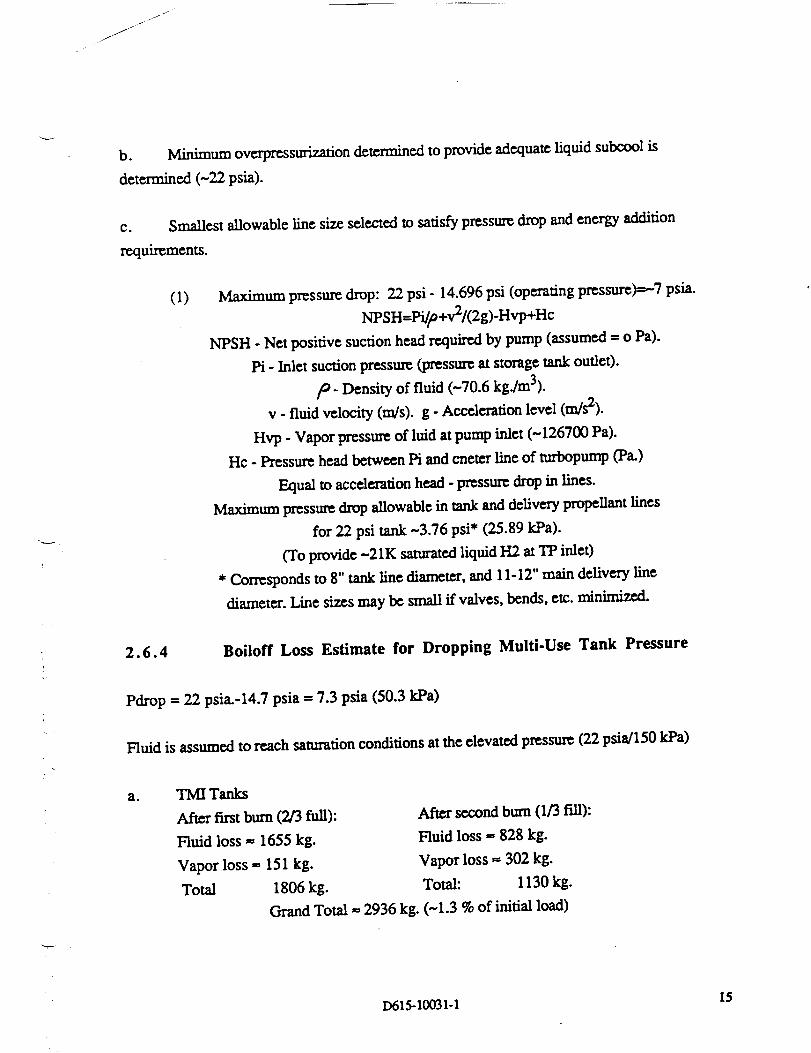
b. Minimum ovcrpressurization detcrmincd to provide adequate liquid subcool is
determined (-22 psia).
c. Smallestal.lowablclinesizeselectedtosatisfyprcssm,_drop and energy addition
rexluiremcnts.
(i) Maximum pressuredrop: 22 psi- 14.696psi (operatingprcssurc)=-.-7psia.
NPSH=Pi/p+v2/(2g)-Hvp+Hc
NPSH - Net positivesuctionhead rcquir_ by pump (assumed = o Pa).
Pi - Inlet suction pressure (pressure at storage tank outlc0.
/o. Density of fluid (-70.6 kg./m3).
v - fluid velocity (m/s). g - Acceleration level (m/s2).
Hvp - Vapor pressure of luid at pump inlet (-126700 Pa).
Hc - Pressure head _twccn Pi and cnctcr line of turbopump (Pa.)
Equal toaccelerationhead -prcssur_drop inlines.
Maximum pressuredrop aUowablc intank and deliverypropellantlines
for22 psi tank -3.76 psi* (25.89kPa).
(To provide-21K saturatedliquidI-L2atTP inlet)
* Corresponds to8" tanklinediameter,and 1I-12" main deliveryline
diameter.Line sizesmay bc small ffvalves,bends,etc.minimized.
2.6.4 Boiloff Loss Estimate for Dropping Multi-Use Tank Pressure
Pdrop = 22 psia.-14.7 psia = 7.3 psia (50.3 kPa)
Huid isassumed toreach saturationconditionsattheelevatedpressure(22 psia/150kPa)
a. TMI Tanks
After first burn (2/3 full):
Fluid loss -- 1655 kg.
Vapor loss = 151 kg.
Total 1806 kg.
After second bum (1/3 fill):
Fluid loss -, 828 kg.
Vapor loss _ 302 kg.
Total: 1130 kg.
Grand Total ,,, 2936 kg. (-1.3 % of initial load)
D615-10031-1 15

The fluid losses can be reduced by designing a thermal protection system, and tank
pressurization system that reduces the parasitic heat leak to a minimum, during engine
burn.
2.6.5 Summary and Conclusion
a. Turbopump selection will likely drive both pressurization and delivery system
design. The main focus of this study was deriving a satisfactory procedure for system
design, given pump inlet fluid condition requirements.
b. Process can be automated by assembling the major elements into a computer code.
Improved tank pressurization/heating codes will improve confidence significantly.
c. Assumptions of propellant line bends, branch lines, valves, etc. resulted in
uncertainty in overall pressure drop calculations. Therefore, pressure drops resulting in Pi
values in the range of 22 to 26 psi considered reasonable.
d. Pressurization system selection:
(1) Initial and start-up pressurization - Helium system selected due to its
simplicity and reasonable low overall system mass (--0.4% of propellant mass).
Internal and external systems are close enough in mass to facilitate the decision to
be made based on operational and safety considerations.
(2) Remaining pressurization, after start-up, provided by H2 bleed fi'om
turbopumps, because of the prohibitive mass penalty associated with helium use
(>10mfftank).
e. Allowable temperatureforturbinebleedinletgas may be higherthan~lOOK ff
helium thermal"blanketing"effectfactoredin.
f. H2 recircularion system may be required for propellant supply lines in order to
avoid fluid "geysering", unless adequate insulation is provided. Initial analysis suggests
that approximately 1" MLI is adequate.
k j
D615-10031-1 16

FIGURE 2-I
751_NERVAdem_
enlineH)
c
i
TMIum_f2_
NTR H2 PROPEI.,L.ANr FLOW SCHEMATIC
GH2 ,Ipressuram
_nks
I LH2 topump inlet.from tanks
T_ O)
GH2 to
turbopump$- I _ Ld_2 to engine andnozzle cooling
15o:1Cookducdon
FIGURE 2-2 NTR THREE TURBOPI.rMPENGINE SCtEMATIC
I:)615-10031-1 17

Jr2)
Lo_mf$1ms,_-'s
FIGURE 2-3 NTR H2 AND He GAS TANK PRESSURANT FLOW SCHEMATIC
M/J&
l
l
l
!
II
uL_F |
I
r4) I
!I
I
I
, !I
F_I del_e_
!
!
/ 'I
FIGURE 2-4 H2 TANK SCHEMATIC
• i
i
D615-10031-1 18

y
_amre ertm_, ptlm_ Sm,,,d_ I'_0qg
pm.p_
]-12p_ IJ_ lindp._m_ p._ c_ly
Sizerange 6m 12inch 03 m 2inch
Tempnmgc 20w 180K 10Ow 12DOK
l_uze nmge 0m221m 0m I000Im;i
l=lownuenmge 0m3"7kg/tec 0ml kf,/m=
Geae_ r-tinhornIW_hnmmndilieamg
Pmpul_veemm 1-12flo,,
CmldownH2nmv
_ moR,z_
H2fl,,iammm_
makWemmm
f-dincool-n|
RI:_@tmsun_
FIGURE 2-5 FLUID LINE CHARACTERISTICS
Mass flowroteofI&.12= 217.8kg/sec,l._ngthofLH2 line- 10ft(30.5m).
Volume flowrate= 3.085m_sec.
Additionallinelosses:4.90" bends,2-45"bends,2valves,3 linebranches.
Vel (rn/sec_ Re,* _ ]f,f_mm
303 (12") 42.3 17166 .0270 2.36 2.702
35.6(14") 31.1 14714 ..0277 2.36 2.376
38.1 (15') 27.1 13734 .028 2.36 2.242
40.6 (16") 23.8 12875 .0286 2.36 2.146
43.2 (17") 21.1 12119 .0297 2.36 2.1
45.7 (18') 18.8 11444 .03 2.36 2.001
50.8 (20') 15.2 10300 .0305 2.36 1.831
55.9 (22") 12.6 9363 .0308 2.36 1.68
61 (24") 10.6 8583 .032 2.36 1.58
_/6(26") 9.01 7923 .0323 2.36 1.492
pdrop (kPa}
319.42
161.31
118.94
89.97
69.89
54.36
34.27
2238
15.62
!1.04
FIGURE 2-6 STS PROPELLANT LINE SIZING EXAMPLE
D615-10031-1 19

i \
J '%1_ nc.ps/xc_ _ u.._ .-- r,,,e,,n,.u,
10/25 14 18 _./55 26 30
LineDiameter(in/an.)
N'rltTmU/puV'_-_9 n
• Results relatively close to STS actual line diameter (IT').
• Actual STS line sizing procedure more complicated; Includes iterations due to
available fluid acceleration head, turbopump design limitations, standard line
sizes, etc.
FIGURE 2-7 STS LINE SIZE DETERMINATION EXAMPLE
MIss flow rote of LJ'_ m _).8, 73.6, ! 10,4 _ Lmtgth of LJ.12 line - 40 m.
Volume flow rate- .$213,1.043, 1.564m_s_..
Addithmal lhn Jmseu: 2- 45" _u_Js, 3 valves,2 llnebmss:bes,I sha_ exit(toafttank).
Vel r m,,'see_ Red f _ _
2.54 (1") 1029 34805 .023 3.14 36.3 1._x10 _
4
5.08 (2") 15"71 17405 ,02"7"2. 3.14 21.5 5,745x10
7.6 (3") [ 14.3 11602 .03 3.14 15.8 8712.6
I0 "y(4") 64.3 8702 .031 3.14 17.2 27.38.1
12.7 ($-) 41.2 6962 .034 3.14 10.7 827.I
L5.2 (6") 28.6 $806 .0"35 3.14 9.2 355.9
20.3 (8") 16.1 4358 .039 3.14 7.7 99.0
n
25.4 (I0-) 10.3 3485 * .0425 3.14 6.7 36.7
30.5 (12) 7.14 2901* .044 3.14 5.g 16.1
8", 11", tnd 13" line sizes selected for 1, 2, and 3 engine cases, respectively.
* Flow in critical region.
NTR MAIN PROPELLANT LIIqE DETERMINATION
D615-10031-1 20

7f -j
jJ
- 75 klb Thrust Engines -
1400
1200
w
2oo-
1000 k2a "_o
2_
S_l_-_d Si_-s based on Pdro_ vs.
_"'- threeengines (-13" - est.)
twoengines(-.!I')
me ensine(S
['-I4 6rl5 | 1C_3.5 t2 14/'45
Line Diameter (indcm.)
FIGURE 2-9 HYDROGEN LINE SIZING ANALYGIS RESULTS FOR 1, 2, AND3 ENGINE NTR
Mms flow rote of 1J42 ,, 36.J, 73.6. 110.4 _. Lenl_h of L212 line- 40 m.
Volume flow ntte= .5213, 1.043, 1.564m3/sec.
Additionallinelosses:2 - 45" bends, 3 valves,2 line_, I sha:p exit(toafttank).
yetcrn_,c_ I_ [ k4nm l_=$
2..54 (l-) 514.3 !7401 .02'/ 1.2S 21.3 2.104x10
5.08 [2") 128.6 8"/02 .0315 ! ,,.2S 12.4 8.0x10 s
7.6 (3-) 5"/.2 5801 .036 1.28 9.45 17.36.6
10.2 (4") 32.2 4351 .039 !.28 9.0 328.3
12.7 (5") 20.6 M85* .042 1.28 6.62 118.6
15.2 (6") 143 2903* .044 1.28 5.8 51.O
20.3 _-) 8.04 2176"* .0305 1.28 3.0 9.79
2_.4 (10-) 5.14 1739 ** .037 1.28 2.91 3.908
30.5 (12") 3.57 1450"* .044 1.28 2.90 1.879
Tmt.rrm//'ff,m#l
6", 7.P', and 9" line sixes selected for 1, 2, and 3 engine cases, respectively.
* Flow in crilical _;,;rm.
*" Flow in laminar., .';,m.
FIGURE 2-I0 NTR TANK PROPELLANT SUPPLY LINE DETERMINATION
D615-10031-1 21

- 75 klb Thrust Engines -
"_O,
_o _'_ ol - _ ._
Se_ _i,_ hLcedon Pdmoy$. diam_r smutlv_5only
drameniin_ (.-9")
twoengines(-?.Y')
onec=!_¢ (--6")
m 1EnSms• 2 Engimm= 3_
loft5 12 14_35
FIGURE 2-I I TMI/MOC TANK LINE SIZING ANALYSIS RESULTS FOR I, 2, AND
3 ENGINE NTR
Selected PI = 22 psia. (151.6 kPa.)
Tnnk i,lne Dis- flnJcm._ Delivery Line DI2. (InJem.'l
41 I0 8120 74.3 1512.1
6/15 8/20 37.91261.2
6 / 15 10 / 25 29.6 / 203.8
6/15 12/30 26.8/184.9"
8 / 20 8 / 20 32.5 / 224.4
8 / 20 10 / 25 24.2 / 167.0"
8/20 12/30 21.5/148.1"
10 / 25 tO / 25 23.5 / 162.3"
10 125 12 / 30 20.8 / 143.5"
* Denotes acceptable candidate line size combination.
FIGURE 2-12 FINAL LINE SIZING ANALYSIS BASED ON ALLOWABLEPRESSURE DROP
v
D615-I0031-I 22

f--
j Jr
_J
, AEROBRAKE INTEGRATION
During the cm'rent technical directive, the study addressed materials and structmal concepts
for the aerobrake. The initial work is being performed for the I.JD=0.5 aerobrake
configuration which was developed in the Phase I work.
3.1 Properties and Processing of Intermetallic TitaniumAiuminides
3.1.1 Abstract
Although full maturity of the technology is at least ten years in the future, intermetaUic
titanium aluminide-based alloys are expected to compare favorably against superalloys in
weight critical aerospace structures where high temperature strength, high elastic modulus,
and resistance to oxidation is required. Titanium aluminides have been suggested for a
reusable Mars excursion vehicle (MEV) for precisely these reasons (Reference 3-1).
Successful use of titanium aluminides in such applications requires a detailed understanding
of material properties and limitations. The focus of this study has been to examine the
properties and processing characteristics of these materials with a goal of identifying
specific technology development needs.
3.1.2 Introduction
Interrnetallic phases within the titanium-aluminum system have been known to exist for
over 30 years (Reference 3-2). In many applications, these hard, brittle compounds were
considered undesirable because they tend to form at grain boundaries causing a reduction in
toughness and ductility. Similarly, titanium alloys reinforced with alumina ceramic fibers
resulted in brittle failure of titanium alumim'de intermetaUic compounds at the fiber/matrix
interface. Since about 1973, however, titanium aluminides have been under investigation
for theirpotentialuse in lieuof nickel-basedsuperalloysin aircraftturbineengines and
hypersonic vehicle structures.Work has focused both on dispersionstrengtheningof
titanium matrices by precipitationof intermetallicphases and upon creation of new
structural alloys based on titanium aluminide intcrmetallic compounds.
Atomic bonding in titanium aluminide intermetallics is not entirely metallic in nature; there
is a degree of covalent character such that the valency electrons are not entirely mobile
within the material. The electrons may be considered to be constrained within a specific
D615-10031.1 23

lattice by hybridization of titanium's 3p and 4s orbitals. This hybridization of bonds is
believed to contribute to lattice ordering which is a major factor explaining the high
temperature strength and stiffness of titanium aluminide compounds.
3.1.3 Alloying Elements and Their Effects
Commercially pure titanium is an allotropic material, existing in the HCP lattice structure
(alpha phase) below 882"C and BCC lattice structure (beta phase) above 882"C. Alloying
elements are added to titanium primarily for three reasons: 1) to change the phase
transformation temperature and thereby stabilize or adjust the relative amount of each phase
present: 2) to cause solution strengthening or improve the maxtensitic haxdenability of the
resulting alloy; and 3) to improve some specific property such as oxidation or corrosion
resistance. Aluminum has long been an important alloying element in commercial titanium
alloys. Addition of aluminum in the range of 20-50 atomic percent aluminum (10-35
weight per cent aluminum) provides solution strengthening and significantly increases the
transformation temperature (beta transus). The titanium-aluminum equilibrium phase
diagram, as it is currently understood, is shown in Figure 3.1 (Reference 3-3).
Substitutional alloying elements perform essentially the same function in titanium
aluminides as in conventional (disordered) titanium alloys, such as Ti-6A1-4V, if they do
not enter into the ordering reaction to a significant degree. Tantalum, vanadium, and
niobium are the preferred substitutional beta stabilizers because they are isomorphous the
beta phase titanium. The addition of vanadium makes complete beta-to-alpha
transformation upon cooling impossible and therefore can be used to control the portion of
beta phase which is stable at room temperature. Zirconium is unique in that it is
isomorphous with both the alpha and beta phases of titanium and may be used to solution
strengthen titanium alloys without affecting the transformation temperature. Niobium,
vanadium, and molybdenum are often used to improve both strength and oxidation
resistance of titanium alloys (Reference 3-4).
3.1.4 Properties of Titanium Aluminide lntermetallics
Of the four intermetallic phases depicted on the titanium-aluminum equilibrium phase
diagram (Ti3Al, TiA1, TiAI2, and TiAI3), only alpha-2 (Ti3AI) and gamma (TiA1) based
alloys axe presently considered to have commercial significance. The others have not
proven feasible to produce using current processing practices due to the narrow
,,._I
D615-10031-1 24

composition ranges over which they exist and their high rate of strain hardening. Since
alpha-2 and gamma based alloys are the focus of the majority of titanium aluminide
research, the majority of this study is directed toward the characteristics of these
compounds. Some of therelevantpropertiesof alpha-2and gamma titaniumaluminidesin
comparison with a conventionalTi-6AI-.4Valloyarc summarized inFigure3-2 (References
3-4, 5, 6, 12 & 13).
a. Yield Strength and Elastic Modulus - The high yield strength and elastic modulus
which is characteristicof titanium aluminide compounds at temperatures approaching
approximately one-halftheirmelting point (Tin)isbelievedtodepend upon thedegree of
long range ordering.Ordering leadstosomewhat strongeratomic bonding; thestrengthof
these bonds being proportionaltoelasticmodulus. But perhaps a more significantfactor
affectingmechanical propertiesisthe behaviorof crystallinedefectsknown as anti-phase
domains. In both alpha-2and gamma titaniumalumirn'des,anti-phasedomains may consist
of stackingfaultsaswell as unfavorableatomic interactionsbetween "nearestneighbor"or
"nextnearestneighbor" atoms. Compared torandomly dispersedsolidsolutionsof similar
composition, ordered intermemlliccompounds exhibita high degree of resistanceto slip.
Anti-phase domains play an important rolein thisbehavior. However, mechanisms by
which thisoccursare not fullyunderstood (References3-7 and 3-8).
b. Ductility and Fracture Behavior - Titanium aluminides are notoriously brittle at
ambient to moderate operating temperatures. The elongation of alpha:2 compounds is only
about 2% at tomperatures below approximately 0.5Tin. Thus far, a maximum of about 5%
elongationin thistemperaturerange has been achieved by modifying thecompound. The
brittlenessof ordered alloysis attributedto a lack of sufficientslipsystems to permit
deformation atthe grainboundaries. Studiesof otheraluminide compounds indicatethat
ductilityissu'onglydependent upon the superlatticestructureand mildly dependent upon
the degre,c of long range ordering. Fractureof intermctaUiccompounds most frequently
resultsfrom int_rgranularclevagearisingfrom a buildup of dislocationswain energy.
Above approximately 0.5Tm, increasedcross slip,dislocationclimb,and other thermally
activateddislocationactivityresultsin higherductility.Consequently, a brittle-to-ductile
transitionisobserved. Methods of improving the low temperature ductilityof ordered
materialsincludethe selectiveuse of alloyingelements,controlof grainsize,and thermo-
mechnical processing techniques. The addition of small quantitiesof niobium, for
example, isfound toreduce the brittle-to-ductiletransitiontemperatureof Ti3Al to about
D615-10031-1 25

600"C by the formation of Nb2A1. The success of alloying elements in improving low
temperatu_ ductility is believed to lie in the ability of favorable constituents to segregate to
grain boundaries and relieve localized swain. Dispersions of niobium aluminides are
thought to enhance titanium aluminides by this mechanism (Reference 3-9). Improving the
ductility of intermetallic ma_ at low to moderate operating temperatures continues to be
the subject of intensive research.
c. Oxidation Resistance - The oxidation resistance of aluminide compounds is high
because all of these compounds contain a large atomic fraction of aluminum. The higher
the aluminum content, the higher the oxidation resistance. For this reason, the TiA13
compound has been suggested for use as an oxidation resistant coating material for other
titanium aluminidc compounds. Aluminizing of titanium aluminides might be accomplished
by thermal spraying, molter metal dipping, or pack cementation. Upon exposure to high
temperature oxidizing environment, titanium aluminides readily form an adherent titania
(TiO2) and/or alumina (A1203) scale which protects the substrate alloy from further
oxidation, see Figure 3-3 (Reference 3-10). Certain alloying agents such as niobium,
when added in sufficient quantity have been shown to improve oxidation resistance up to
850"C by entering into ternary re.actions which promote the formation of titania and alumina
products.
d. Strain Hardening - Long range ordered alloys usually exhibit high strain hardening
rates compared to their disordered counterparts, making them extremely difficult to
process. However, in the Ti3AI lattice, the strain hardening rate is substantially unaffected
by temperature up to about 700"C. Studies show that the strain hardenability of gamma
Ti3AI + Mo alloys increases proportionally with stress amplitude below 700"C by a build
up of planar bands of basal dislocations (Reference 3-11). The role of superlattice
dislocations in strain hardening is the subject of ongoing investigations, but the strain
hardening phenomena of Ti3A1 enables the alloy to be strengthened by thermo-mechanical
processing techniques which are similar to conventional methods. Strain hardening is also
expected to improve erosion resistance of intermetallic alloys, in some cases abrigating the
need for protective surface coatings.
L'
V _
3.1.5 Fabrication and Processing Techniques
ALloys based on alpha-2 titanium aluminides are now being demonstrated in a wide variety
of parts utilizing both conventional and innovative new manufacturing technologies.
D615-I0031-I 26

Research and development for specific applications is continuing at the Air Force Wright
Aeronauticallaboratoryand atnumerous aerospacecompanies. Some of the applications
which have been demonstrated are listed in Figure 3-4 (References 3-3, 3-5 & 3-14). The
basic difficulty being experienced in development arc problems of reproducibility and
homogeneity. Titanium aluminides are more sensitive to property variations as a result of
small changes in composition or processing conditions than conventional alloys, and arc
therefore more difficult and more expensive to process.
Bulk form titanium aluminides are normally obtained by powder metal processing (e.g. hot
isostatic pressing), or by vacuum arc melting and casting. Forming may be accomplished
by high temperature extrusion or a procedure of repeated cold roiling and recrystallization
to sequentially reduce gauge thickness. Rapid solidification techniques, such as drop
casting and melt spinning, have been successfully used to refine grain size and limit
segregation during solidification. As might be cxpe, eted, intcrmctallie alloys arc difficult to
forge. Additions of reactive alloying elements arc being investigated to improve hot
formability and recluee sensitivity to metallurgical impurities and contamination.
3.1.6 Summary and Conclusions
In summary, intcrmetallic phases of titanium aluminide which have been known to exist
since the early days of titanium metallurgy am now being developed for applications in high
temperature aircraft turbine engine and hypersonic vehicle strucna'cs. Very low ductility at
ambient to moderate operating temperatures continues to be the major obstacle to their
widespread use. Metallurgical engineers are actively pursuing research related to
deformation behavior, with a goal of designing new alloys which overcome the inherent
limitations of this class of materials. Selective use of alloying elements, grain size control,
and thermo-mechanieal processing techniques arc the prima_ means of modifying material
behavior. However, most properties and characteristics arc directly attributed to the basic
lattice composition and structure.
Fabrication technologies using alloys based on alpha-2 titanium aluminides arc currently
being demonstrated in prototype hardware. Many of the conventional processing
methodologies may be adapted to these ordered compounds, but careful attention must be
paid to process control in order to minimize variability of physical properties in the finished
product. Difficulties in fabrication make titanium aluminide parts very expensive to
D615-10031-1 27

produce. Nevertheless, the trend towards higher performance in weight critical aerospace
applications makes continued development impe_tive.
3.2 Aerobrake Structural Integration
A totalof nine tasks arc planned for developing and trading aerobrake structural
configurations.Three of the tasks,literaturesurvey,preliminarysizing,and analysistool
reviews were completed for one con..Igurationof the aerobrake. The fourthtask,which
included constructinga preliminaryfiniteelement model, was initiated.The remaining
tasksrulatetotheanalysis,optimizationand structuraldesignfortheconfiguration.
Groundrulcs and assumptions which were establishedpriortotaskcommencement are as
follows:
a. The baselineaerobrakegeometry isthecurrentBoeing L/D 0.5aerobrakeconcept.
b. Payload (MEV) mass is83 metrictonncs.
c. Maximum deceleration(duringaerocapturcmaneuver) is6g ata relativewind angle,
RWA = 20 degrees.
d. 6g aerocapmm isworst case.
Three tofivesu'ucua-alconceptswillbc analyzedand developcd forminimume°
mass.
f. Materialselectionswillbe based on concurrent,independenttradesand technology
projectionswhich areoptimizedforeach structuralconcept being considered.
The specifictaskresultsarediscussedbelow.
a. Task 1, Literature Review - Aerobrake structural work performed by North
Carolina State University and NASA Langley Research Center was reviewed to ensure that
there would be no unnecessary duplicationof effort. It was determined that,due to
differencesin assumptions and aerobrakegeometry and structuralconcepts,the previous
work was incornplcteand did not provideenough evidcncc fortradingallcurrentconccpts.
b. Task 2, Design Configuration-The fastconcept chosen foranalysisconsistsof a
semi-monocoque shellof sandwich constractionwith advanced composite / laminate
materials. For purposes of preliminarysizingfor inclusionin the initialfiniteclement
model, the shcllwas assumed to be a monolithicshellof sphericalsection.The material
-I
D615-I0031-I 28

-,,..r_k
was assumed to be titanium A uniform sandwich configurationwas thendeveloped which
provides stiffnessequivalenttothe monolithicshellata reduced weight.
c. Task 3, Design Simulations - The capabilitiesand limitationsof ANSYS and
NASTRAN finiteelement programs were reviewed to evaluate their suitabilityfor
performing stressanalysis of aerobrake structures.Specifically,the available f'mite
elements and program featureswillbe considered in selectingan appropriateprogram for
mathematical simulationand analysisof theacrobrakestructm'es.
The ANSYS program has beam, shell,solid,and composite elements tosimulate different
design configurations. Italso has compatible thermal elements to perform coupled
thermal/stressanalyses.The followingare applicableelements foraerobrakeapplication.
(1)
(2)
(3)
(4)
(5)
(6)
(7)
(8)
(9)
(10)
3-D spar, STIF8
3-D beam, STIF4
3-D plastic shell, STIF43
3-D quadrilateral shell, STIF63
Isoparametric shell, STIF93
Isoparametric solid, STIF45
Anisotropicsolid,STIF64
Layered composite shell, STIF91 and STIF99
Layered composite solid, STIF46
Reinforced composite solid, STIF65
Combinations of the above elements will be used to simulate different design
configurationssuch as monocoque shell,space frame, stiffenedsemi-monoeoquc shell,
etc.The layeredelements willbc used forcomposite materialapplications.The capabilities
and featuresof each element arc summarized inFigure3-5.
Nastran has thefollowingelements formodeling acrobrakestructures:
a.
b.
C.
d.
CBEAM
Triangular shell, CTRIA3 and CTRIA6
Quadrilateral shell, CQUAEM and CQUAD8
Solids, CHEX20
D615-10031-1 29

The Nastran elements are similar to ANSYS elements except that they do not support
orthotropic materials. These elements lack other options also, including large deflection,
stress stiffening, and variable element thicknesses but are still sufficient for simulating the
expected aerobrake structural elements. The Nastran program does not provide a wide
choice of elements for modeling composite materials as ANSYS does. A summary of
Nastran element features is given in Figure 3-6.
In summary, both ANSYS and Nastran elements can adequately be used in developing
finite element models of the aerobrake structures. ANSYS, however, has elements more
suitable for modeling composite materials. It also has extensive pre/post-processing
capabilities which Nastran lacks. Other useful features of ANSYS include design
optimization and a larger dement library compred to Nastran and may therefo_ be a better
choice to model and analyze aerobrake structures.
d. Task 4, Preliminary Finite Element Model - Due to its immediate availability,
IDEAS Supertab was used for pre-processing and preparation of the initial aerobrake
model. This model wiU be converted to ANSYS for analysis and subsequent iterations
and/or modifications.
i
The preliminarymodel consistsof thinshellelements which definethe aerobrakegeometry.
These elements arc loaded by element face pressures as calculated in an separate
aerodynamics analysis.The pressureloading isvariableand ranges from 0 atthe aftlip
sectionto 13,675 Pascalsatthe stagnationpoint.The loaded model isshown inFigure 3-
7. Note thatthe pressm'cvectorsdo not representmagnitudes and arcnot scaled.A scaled
left-sideand frontviews of thepressuredistributionsarcshown inFigure 3-8.
Physicaland material propertiesarebeing finalizedforinclusionin themodel.
D615-10031-1 30

3.1
3.2
Boeing Aerospace and Electronics, NASA Contract NAS8-37857,
Concepts and Analysis for Ext_loration Missions, 4th Quarterly Review, Oct. 17,
1990, pp. 4-32 - 4-35.
The use of the term "intermetallic" is the subject of some controversy. For
purposes of this text, all intermediate phases which exhibit a intermextiat..- to long
range ordering and a degree of covalent bonding behavior shall be regarded as
"intermetallic".
3.3
3.4
3.5
3.6
3.7
3.8
R. N. Boggs, ed., "Titanium Aluminide: True Space-Age Material,"
News, Calmers Publishing Co., June 19, 1989, reprint edition.
I-L E. Boyer and T. L. Gall, eds., Metals Handbook. Desk Edition, (Metals Park,
Ohio: American Society for Metals, 1985), p. 9-2.
H. A. Lipsitt, "Titanium Aluminides - An Overview" High Temt_erature Ordered
Intermetallie Alloys, Materials Research Society symposia proceedings, Vol. 39,
('Pittsburgh, PA: Materials Research Society, 1985), pp.351-364.
Texas Instruments, '_I'i Aluminide Data Sheet," Rev. 3, March 28, 1990.
D. Sheehtman, M. J. Blackburn, and H. A. Lipsitt, "The Plastic Deformation of
TiAI," Met. Trans., Vol. 5, 1973, P. 1373.
S. M. L. Sastry and H. A. Lipsitt, "Plastic Deformation of TiA1 and Ti3AI,"
Proceedings of the 4th International Conference on Titanium, Japan, Nov. 1980, P.
1231.
3.9 N. S. Stoloff, "Ordered Alloys for High Temperature Applications," tJdyda
Temperature ordered Intermetallie Alloys, Materials Research Society symposia
proceedings, Vol. 39, (Pittsburgh, PA: Materials Research Society, 1985), PP. 3-
27.
D615-10031-1 31

3.10
3.11
3.12
3.13
3.14
M. Yamaguchi, U. Umakoshi, and T. Yamane, "Deformation of the Intermetallic
Compound A13Ti and Some Alloys with An A13Ti Base," _Iigh Temperature
Ordered Intermetallic Alloys II, Materials Research Society symposia proceedings,
VoL 81, (Pittsburgh, PA: Materials Research Society, 1987), pp. 275-286.
N. S. Stoloff, et al., "Fatigue of Intermetallic Compounds," J-Iigh Temperature
Ordered Intermetallic Alloys II, Materials Research Society symposia proceedings,
Vol. 81, (Pittsburgh, PA: Materials Research Society, 1987), pp. 247-261.
J. Rosier, et. al., "The High Temperature Behavior of TiA1 Containing Carbide
Reinforcements," Intermetallic Matrix Composites. Materials Research Society
symposia proceedings, Vol. 194, (Pittsburgh, PA: Materials Research Society,
1990), pp. 241-248.
MIL-I-IDBK-5E, Metallic Materials and Elements for Aero_aee Vehicle Struenn'es,
Vol. 2, (Washington, D.C.: USAF, 1987, p. 5-55.
L. Kempfer, ed., "Materials Take a Hypersonic Leap Into Space," Materials
Fdlgi/lgg_i_, Penton Publishing, Cleveland, OH, August 1990, pp. 19-22.
J
D615-10031-1 32

/
_-- - I_
FIGURE 3-1
ttl
tu
I=-
" _ _, V _, _, "__" . ", . .', ._ . , ....
m-
l
i,lo
tim,
m,
Im.
am.
.,,!
m'
TI
:::::::::::::::::::::::
•,Jc / i_4!;¢
" I
L !_!;,;!i_'._:;:!_:_,_
I I _m 41
1,
m N
m,0_t_
._,_il| (All
AI
'ITI'ANKIM-ALUMINUM EQUK,IBRI'UM DIAGRAM SHOWING THETWO MOST IMPORTANT ALUMINIDES: ALPHA-2 AND GAMMA 3
TI-6AI-4V
(alnha*beta)
Denslty(l_) 4.5
Pleltlng Temp. ('I:) 1700
(pure compouna)
I'lax. Temp for 5:38
C_-eep ('0
Max. Temp for' 59:3
OxlOatlon ('C)
Ductlle-to-e_lttle n/a
Transition ('C)
UT$ (2_C') I I00
(MPa) (700"C) n/a
0.211 Of fset(2.s'C) 980
YS (MPa) ('/O0"C) n/a
Elast. MOO. (GPa) 96 - I00
Elongation (ll)
(c_m 2__c) 2o-_
(c_:s O..%'m) _1gr_
TI:3AI .N_(alpha-2) TIAl*C(gamma)
(alnhe-_*beta) (gamma*T1 AICI
4.2 - 4.7 :3.7 - :3.9
1600 1460
815 1030
649 10:338
600 - 760
940
75O
8:30
810
! I0 - 145
2 - 5X
5 - 811
600- 700
(e4_
640
640
176
I - 2_
7 - 12_
pmpnnc,ra_= int_.mmon.,,.il._ _ otmo_nd'_/s
n/_. n_x tppli:d_= "" = dm _
(4.';.6.12,131
FIGURE 3-2 TYPICAL PROPERTIES OF'ITI'ANIUM ALUMINIDE ALLOYS VS.
CONVENTIONAL TITAN1UM Ti-6A1-4V ALLOY
D615-10031-1 33

'I'102 -- __=2_L:.'e'_,_ ........ :,-......... t: .
A1.203
T_.3AJ.
T.LA1 ---- _
ZODm
FIGURE 3-3 SCANNING ELECTRON MICROGRAPH SHOWING A CROSSSECTION OF THE OXIDE SCALE ON TiA1 AFTER EXPOSURE TO
AIR AT 900oc FOR 200 HOURS
Iavestisating
_nmn.nv/A_eney
AFVVAL
AFWAL
Fabrication
Forging Billet
Shcct Rol//ng
Casting, Mach/ning
Roiled Ring Fo_g/ng
I
Sin=rare/
Tech. Dcmonsuadon
Tm.bine Star.or Support Rings
(45 cm dia.)
AFWAL RolledRing Forging Section Casing
(50 an d_a.)
AFWAL Precision Casling Turbine Blades
AFWAL,, Boeing Fom in DiffusionBonding
Afterburner DivergentNozzleSeal._ W'mg Sdffeners
bir.Donneil-Douglas/DiffusionBonding/
Textron Composite Strucum:
NASP S_ Skin
Texas
Ins_dments/RohrCold Rolling (foil) Honeycomb Core
4
Sources: [3,5,14]
FIGURE 3-4 TITANIUM-ALOE TECHNOLOGY DEMONSTRATIONS
D615-I0031-I 34

. ---
. J-
-..__
F_,lement
s'rlT-43,Pl_ticO.adrUa_ndShell
STIF.63,F._tic
Shell
STIF93,hoVma=_:Shell
No. or _,gneesor Matm-_ Etem_t "rbemudNodes Freedom Leadlag F..iemem
2 UX, UY. U2 hRX, RY, RZ
2 UX, UY, UZ b
4 UX, UY. UZ Is, OrRX. RY. RZ
4 UX, UY, UZ h, OrRX. RY, RZ
g UX, UY, UZ Is, OrRX, RY, RZ
Pl_f_lJl_ or
linear temp.!grsmmm
T, P STIYS7
T,P STW_/
1". PR STIFS"/
Special Feature
Tapenui cross sec.,nodal offsets, sheerdeflection, initialstrain. S, R
Uniaxill tension.compr, P, R. S
Variable thicknessmembnmc & bend-ing stiffmm, P, !_
'S, plasticity can bemmcd off.
Variablemickn_,membnme and/at
bendingsaltiness,reducedmassmalzix
uptio_exut dis-p_:eamt shapesuplnuuioaoption,R,S
Vagablem_:kness,
P,R,S
Appl|cattm_
3D truss, fnuneor uiffener withtension, corapr,& bending
Truss, spring
Nonlinear, flit orwsq_l thin tomodenuely thickshell.
Thin to modemtelythick elastic shell
Curved shell.t
E_-Iemeot
STIF45,Isopsnm_tricShell
STLC64.Anisom3picSolid
STIPgl, or
LayeredShell
STIF65,ReinforcedSolid
No. or Degrees or MatertaJNodes Freedom
8 UX. UY, UZ Is, C_"RX, RY, RZ
8 UX. UY. U2 ANRX, RY, RZ
8 UX, UY, UZ Is, Or
8 UX, UY, UZ Is, Or
8 UX, UY, UZ h
Element "l'nermal Special FeaturesLoading Element
NT, PR STIPTO P,R,S
NT, PR b'WIFTO Anismmpicore_ymdlh'z matemls
T, PR Up to 16 layers &NT material propertiesin
STIPgl &upto 100layem t- STIP99,m slipp.ge baweeatayen var_b_ Wjerthictncss
T. PR up to 100 layen,NT matorial layer proper
by _upem,no slippqe betweenlayen
NT, PR One solid and upto 3reban,capableofcrackingintensio_andcrushingincompress-ion. nonlinear materialproper by specification,plasticity
Ap_Imtion
3D solid modeling
Solid modcling ofanisotmpicenme_ial
Layered compositeshell
Thick Itye_-dcompositeshellor solid
Modeling ofminfomedcompositethickshellsor solids
FIGURE 3-5 FEATURES AND CAPABILITIES OF SELECrED ANAYS ELEMENTS
D615-10031-1 35

F_Jem_t No.of _ olr Maler_ Element ThermalNodes Frtedom Lmdlng F..lemtnt
CBEAM 2 ' UX, bY, UZ Is _re or !
RX. RY, RZ i thmmalgrad_
cTri_A3/ 3 UX, UY, UZ IS, At/CTRIA6 RX, RY, RZShell
CQUA_V 4tS UX, trY, UZ _S,ANOQUA_ ZX,RY,RZShell
T, PR Y
T, PR Y
CHEX20 Solid 8or UX, UY, UZ IS, AN T, PR Y20 RX, RY, RZ
-Special Features Appliathm
Tatx:md crms 31")tnu_ framesectina, nodal offsets m stiffener
P, CTRIA has optional !Thin to moderatelymid sick:node, optional j_i_kshellcoupling of bendingand membml stiffm_
P, CQUAI_ has Thin to moderatelyoptioml mid side nod_ mick shellopt/m_ bending andmembrane _ffneu
coupJhn_
P Solid modeling,thick shell
IS = lsou_tcOR- O_m_AN - Anisoumpic
T = Sudace usmp_qumPR = Surfacepn_ssu_NT= Nodal_
P = ptas_ityR = La._ DcflectionS = Stress stiffening
FIGURE 3-6 FEATURES AND CAPABR.,FrIES OF SELECTED NASTRANELEMENTS
v
:ate ne_ center
FIGURE 3-7 FINFrE ELEMENT MODEL WITH LOADS
D615-10031-1 36

K-
U-
l-S-
Lo :ete
(EY__N..FRRCTIDH;ISIBLEIRCKUP
_BORT
I
/
ne_ clnter
!/
/
L
FIGURE 3-8A SCALED LOAD VECTORS, LEFr SIDE VIEW
J
I-
'..E
1RIH MEHU3RCKUP
-GLOBRL_MEHU
_ECT MEHU#
r//////////1/I/L,,...... .,,,_,_\_\\\\_
L,
FIGURE 3-8B SCALED LOAD VECTORS, FRONT VIEW
D615.10031-1 37

o Assembly Operations and ETO Vehicle Size
Requirements
Within this Phase 1I section of the STCAEM study, initial on-orbit assembly systems for
the NTR vehicle were evaluated for continued study in the Phase III portion of the contract.
To the set of assembly platforms that were generated in the fwst phase of the contract,
(Figures 4.1 - 4.2) several additional concepts were added. A brief discussion of these
concepts are provided.
4.1 Gantry-Rail Platform
This configuration allows access to all parts of the vehicle and gantry with storage and
support platforms to be attached to the upper surface of the rail away from the vehicle ( no
interference with the track), Figure 4-3. The vehicle is held by standoffs from the rail
which may be easily removed after vehicle departure. The mobile gantry is large enough
to clear all parts of the vehicle including the tanks and aerobrake. The rail itself is a
reinforced, but still light truss-type structure. The First Element Launch (F'EL) will be
requi.,_ to deploy, assemble the system and make it operational.
The concerns are:
(1)
here).
(2)
help).
The gantry may have to be counter balanced (storage platform may help
There may be a vehicle balance problem (again storage platforms may
(3) The rail will have to be stiff to keep the gantry centered.
(4) Detachment of the vehicle from the platform will require some delicate
maneuver capability on both the vehicle and platforms' parts.
(5) The rail joint-truss release my not be simple.
The advantages arc:
(1)
(2)
(3)
(4)
It is a relatively simple platform.
It has low mass.
The attachment points are generally simple.
It has full access to the length and circumference of the vehicle.
v
D615-10031-1 38

(5) Itcan be mused easilyor be used forotherpurposes on orbit.
4.2 Modified I-Beam with Lazy Susan
This is the same configuration described by the Phase I I-Beam arrangement with the
additionof the turntablethatattachesbetween the vehicletrussand the platform central
beam, Figure 4-4.All the advantages and disadvantages of the I-Beam form arc present
with theadditionof an extended reach advantage atthe priceof some complicationin the
"lazy susan" turntable.
4.3 Common Hab and Assembler/Servicer
This configurationinvolvesmodifying a pressurizedMTV crew habitatwithan ACRV and
airlockby reinforcingthe end domes and attachingroboticarms tothem and reinforcinga
circumference panel to accept an articulated RMS arm and power/control cable, Figure #,-5.
It attaches to the NTR truss by the circumference panel RMS and maneuvers around the
vehicle and along the truss. It is crew controled and will run off the vehicle facilities. A
FEL will be required to initiate the operations.
The concerns arc:
a. It requires a redesign of the NTR MTV habitat.
b. The complexity of the habitat increases greatly.
c. Manipulating the robot arms with limited visibility may be a sensitive operation.
d. It is almost free floating and when maneuvering objects, particularly massive ones,
will have to be secured.
e. It has very limited storage.
f. It may increase orbital operations time.
g. It may have limited reuse.ability.
h. It requires extensive crew involvement in the operations.
i. It may require early launch of auxiliary or disposable systems such as power
(arrays).
The advantages are:
a. No unnecessaryinfrastructure.
D615-10031-1 39

b.
C.
The assembly crew is present during operations.
The Assembly/Servicer may or may not be used as the MTV Transit Hab.
4.4 Tethered Robotic Assembly Platform
This platform consists of a long beam perpendicular to the NTR truss that has a continuous
tether system anchored off the ends of the NTR truss, Figure 4-6. At least a pair of,
possibly four, mobile RMS robots travel along the tether to pick up parts stored on the
beam and assemble the vehicle. These robots can rotate about the tether. The beam is long
enough to allow the robots to clear the tanks. The power is supplied to the robots by
batteries that are recharged from the platform main power supply. The tether truss is
deployable, but an FEL mission is necessary to deploy the vehicle truss with GN&C,
communications and reboost RCS, attach the central truss and deploy the solar array, attach
the tether system and the MTV habitat module and attach berthing and storage fixtures.
Localized debris shielding will be used on the vehicle to protect it. The tether and tether
beam can be removed from the vehicle and stored on orbit.
The conc(.-_rl$ arc:
?
a,
b.
C.
d.
O.
f.
g.
h.
Refurbishment of thevehiclesystemspriortodeparturemay be difficult.
Vibrationson thetethermay interferewithrobotmovement and operations.
Large objects cannot be stored on the tether, and the storage on the beam is limited.
CTV and delivery vehicle docking or berthing will be delicate operations.
Placement of the solar arrays is still an open question.
The EVA requitm_ents are undefined but likely to be large.
The mode of on orbit storage is still undefined.
The length of the central beam is over I00 meters.
The advantagesare:
a.
b.
C.
d.
Itisa deployable structure.
Itcan be discardedafterthe vehicleassembly iscomplcte.
Itcould be launched inone flight.
Itwilllikelyhave relativelylow cost.
D615-10031-1 40

4.5 Assembly Ball Platform Concept
This isan assembly box similartothe gantryin the Gantry -RailPlatform design,except
that there is no rail and the gantry is mobile on the NTR truss itself, Figure 4-7. The
assembly ball is self contained in power, thermal control, communications and storage. The
robotic arms are mobile over the lip of the ball therefore they can work inside or outside the
ball. The concerns and advantages are shown in Figure 4-8.
4.6 H-O Assembly Platform Concept
This platform is a large strong truss structure that is a modified Gantry -Rail Platform with
a large attached non-mobile truss bay opposite the vehicle assembly area and no mobile
gantry, Figure 4-9. The function of the mobile gentry is taken up by the platform robotics
for component placement after the component has been assembled in the bay area. The
concerns and advantages are shown in Figure 4-10.
4.7 General Requirements
All the assembly platforms will fly in a gravity gradient stabilized mode. These were
evaluated against a set of known requirements and common sense criteria. The known
requirements must be satisfied either by the platform itself or a combination of the vehicle
and platform together. There is the tendency to burden the platform with most of the
shared needs in order to prevent degradation of critical Mats vehicle systems. Core
requirements that must be satisfied arc: the ability of the platform-vehicle to have reboost
eapability for orbit maintenance, GNC and communications station (EVA and robotic),
storage space for equipment not in use and parts, berthing space for a CTV (cargo transport
vehicle) and/or the delivery vehicle, sufficient power and power distribution prior to,
during and after the vehicle is at the platform, adequate lighting for both robotic operations
and EVA including transition in occultation, thermal control for the platform (perhaps
temporary for the vehicle) equipment, accessibility both by EVA and robotic arms to all
portions of the vehicle, robotic arms for assembly operations, position reference sensors
for platform/robot/vehicle relative positioning, vehicle and equipment tie-downs to the
platform, EVA tic-downs, local or global debris shielding, EVA housing for astronauts
working around the vehicle-platform (may be provided by the CTV) and safety/escape
provisions for these astronauts. These requirements had to be judged in the light of
reasonable expectations of program and vehicle demands. That is, we could not expect to
D615-10031-1 4 __

have the platform and its construction put a demand on the development costs, launch
schedule and complexity or the on-orbit operations equal in magnitude to the construction
of the Space Station, neither could a platform system be inflexible to the point of excluding
the known NTR vehicle design set nor create a major impact to the top-level NTR
configurations. These evaluations could, for the most part, be accomplished without the
subsystem level NTR configuration being completely identified. The results of this
analysis is given in Figure 4-11.
13615-10031-1 42

j--
J7
_j
+
ET-bnsed Platfom
"Smarl" IILLV
I
"l-llmm"
• ,..,
Assembly Flyer
FIGURE 4-1A ON-ORBIT ASSEMBLY CONCEPTS
Fiexihle (Hln_'d) Truss
SSF-based FEL Assembly
I
" T [
I:+
1 - ==+__u,. _'M
Vehicle u IW Own Platform
1191
Telhered.Off.SSF Assembly
FIGURE 4-IB ON-ORBIT ASSEMBLY CONCEPTS
D615-1(X)31-1 43

Node Con__ntl
Dedicated AtKmbly Node
!-_ P_onu.
"Smm1" HLLV Plaffmm
|
HingedTom Platfenn
Vehicle u |m ownPlatt'onn
Key Feature_Advantaue_• Almmlml mmlP• Tm_ir_• vlMel, m m_• l,r,,le_ mlmt m• Smlmm d veldde mat Im**madb_
8Um vddde furminer, din. RCS.
. L'= "-,,,e q sine_, ,.__•No_ido_ tlmfonu_lelml•m.Lv_nmdmmtdmUmheddd_ _eJe_•m.Lvmevtdm_ m_mimem, dm. ItCS.ONC, mr.,.
• Robinmine mmfm_ mNTR
•Um vels_ u-msia mmaW l_rmR moma pbu_ meded
• Ite,_ to mmommitre _eoa d veMr._L_'k_ b,/nmaalmm m I_iat,m
•V_ mbmmm me_ m JUdmmlIT_ nen_
• Itmtm= msded ca-odd* -'---'-._.t_._* Ddetm eddidmvdfactlidesendt_mufeesneede
f_ dadptq. Imilidiq. Imnddq. lad am-mma| m maaMy plmfmm
u i
Key Disadvantaees
. _ l-U._V _• Bekmt fuellurembei_
lllladdy _Fr i T1 --T - - 11 - |
• Itelme_ mmL dmLl_-W, ram*be la ptme iNt_m_mst
• l.lmi_ mmt_le•,_-_.__;d_, _;_II
• _ _ w fM cem fro'Ii _,mm
Node Concents
Assembly Flyer Plllfoen
SSF Based Assembly ofFirst F.I_
Tethered ofr-SSFAssembly Platform
Key Feature_Advantases•eetm, m.t.v m=,a_. :=_d_,, ,m,,-
Key Di_advanta_es
• tto uldkkmd umulu
rdm_m•p.,q,tm,u,e_mm ma_d,u_,, etuq/tlmm mm-ml mm w.W_
, P.,qumimU,,a_rU _,t_
• _ _It c_m SSPdm/p
epenutem
• Remov_ _ o_'ldoal lid Imle'ltll IoSSF_a;stan_
* Impea mSSPnsourcu. IteqUu mfi_ _ ddddiu!• He Idemd sm_• l_uilll Ill _ and 4_III_01 .yllSellll ,,.
ssll
FIGURE 4-2 ASSEMBLY NODE CONCEPTS PROS AND CONS
v
D615-10031-1 4.4

FIGURE 4-3 ON-ORBIT ASSEMBLY CONCEPTS
r
FIGURE 4-4
/ \ /_, /\ /\I \I /!
MODIFIED I-BEAM wrrH LAZY SUSAN
D615-I0031-I 45

• °
._I_-- _._.',-'7- ,
4.*/"iI_-_i_# _ , ,[. i !.
FIGURE 4=5 COMMON HAD AND ASSEMBLER/SERVICER
FIGURE 4-6 TETHERED ROBOTIC ASSEMBLY PLATFORM
D615-I0031-I 46

J
_-J
Internal A,rca > 30 x 30 m
NTR Truss
Assembly Ball Robotics
•NTR Aft Tank and
Reactor/Engine Assembly
•,, ." Assembly Ball Solar Arrays
//
i
FIGURE 4-7 ASSEMBLY BALL PLATFORM CONCEPT
Major Features Major Concerns
• Provides 360" of acorns to particular assembly lu_
• Multi.faceted (squ_, pentagon, hexagon, etc.) smlmm_:
- Pm_tlly deployed (solar _n'ays, booms, etc.)- Partially commuxed (via S'I_, SSF, CTY, etc.)
- May be easily disassembled once NTR cemplete
• Fully self-supporting axgl/or |ynerlgetic with NTR
- NTR _ my be mud to anach ttnlu
- Power, TCS, etc. may be to or fnxn NTIt
-TnmSlxmabJe along NTR tntu
Sized to envelope Aes'osbell for its assembly
External faces allow I_.-Im t_ (m/ll'll_
intemm, etc.) _ some _
,_ _ oneorboth"e_ds"closed
• I.tmttedaerie ap_,S
• limited eoml_ibilL_ with pmamized tue_bly modu_s
vehk:k, eta)
• PLalform n:quin_ some assembly of its own
• May not be as gompatible with muhi-i_r NTR, NEP, SEP
• gefurbishmem operations:
- Captu_ of t_utmag NTR- Nuclear n at:tog w.ied tasks
° R=supply issuesi
• Localized shielding for NTR and platform requiged LLFIGURE 4-8 ASSEMBLY BALL, PLATFORM CONCEPT - FEATURES AND
CONCERNS
D615-10031-1 47

• NTR Truss
/_. H-O Platform Solar Array.:
\H-O MEV Assembly Bay/Storage Hant, :r
FIGURE 4-9 H-O ASSEMBLY PLATFORM CONCEPT
Major Features Major Concerns
• expamtm et "l-kern" p_feem eemep,
• Fully seif_ll with possible syneqlbm with NTR. NTR mtxxic, may be reed to ,aadt alt tmd¢0¢
mmmrerMEV to NTR. Poqt_r. TCS, etc. may be m NTR. Tnmspmmbte along NTR truss
• Allows separam and paxallei MEV and NTR assembly
• Similar to SSF planned tqewth configuration
• MRv membty b,y _o_b_ -. m_,p h_,_
• Man*tond_ modules easily added
• May be compatible with NEP. SEP. and (with additionofsecondbay) CAB
• May serve u expenmem station between assemblyactivities
* Nearly u Imp md ¢ompl_ ,., SSF
. Requk_ dgnifiam Immbly of ia own
• Localized Ihieldloll for NTR andplatform RqutR'd
• Additional mucmre may be mquiRxl to accommodate CTV.STV, STS, e¢. doddnll
• ¢ommllabiliv/of full/neK-complem NTR
• MtneuverinlgMEV to _ (may allow test of MEV/NTRnn_ezvous and docking, MEV propulsion,etc.)
• Resupplyissues
FIGURE 4-10 H-O ASSEMBLY PLATFORM CONCEPT -FEATURES AND
CONCERNS
L :V
D615-I0031-1 4:]

• L
1-14:)Assembly Piadomm
iqml_d "rmu
An,ached to _F:
SSF. FEL Assay
Tethe_d oH SSF Assembly
Accept: will be gi_ firm em.tiden,im t.. the la_TBD: W tam= i.qfm'mati_ to eva,lual=Reject: eliminated [nmn mmidentOea
,/
_ w _ Dcd_mcl _m_
dgs amt'tpmune hw mo m_m/ma_l_mfro-me wi_ _is _c o_ _dcJ=
I
!) cia,_nt dcdp of SSF mty eot _diow_ mw n,_ _r m_md F_mm be .,.,.,,,,h_ to d= im_ mn_*m_
2) the balm_ w SSF _ebed.k:s, b_iki_ sadf_ _ mt _t em=nnined
FIGURE 4-11 PRELIMINARY NTR PLATFORM ASSESSMENT
..--:
I)615-10031-I 49

e CREW MODULES
The Earth Crew Capture Vehicle (ECCV), as configured earlyin the Phase 1 study,was
designed to return four crew to Space Station Freedom following a Mars mission. The
present vehicle has evolved into a direct entry capsule for a crew of six, and is also being
considered for returning four crew from an early Lunar mission. As the evolved ECCV
does not capture, but returns direct to Earth, a more appropriate acronym for the vehicle
might be the Crew Return Vehicle (CRV). Assumptions and mission modes for both the
Lunar and Mars casesare shown inFigure5.I.
There arc currentiyseveral studiesunderway for design of an Assured Crew Return
Vehicle (ACRV) for use at Space StationFreedom, and of a Personnel Launch System
(PLS) thatwould ferrycrew toand from space stationusingan expendable launch vehicle,
such as the Titan Four. Both of these systems arc currentlybeing designed as short
duration(1-10day )crew modules, and thereforehave some commonality with the CRV.
Sources of dataforconfigurationof theCRV, and sizingofit'ssubsystems,arcthe Boeing
PLS, Apollo CM and NASA Langley CERV. The NASA standard3000 isused as an aid
indeveloping efficientand habitablecrew volumes. The reference6 crew CRV isillustrated
in three orthagonal views in Figure 5.2.The Lunar version of the vehicle would bc
configuredwith only 4 crew couches.
V
During thisstudy,questions arose concerning the need for a higher L4D, and greater
crossrangefortheCRV. A decisionwas made tobrieflystudya possibleconfigurationthat
would satisfyboth Lunar and Mars mission modes, and also offer higher crossrange
capability,lower g loads on entry,and greaterlanding siteavailability.The preliminary
configuration for the high I./D CRV is shown in Figure 5.3.
The high I.JDCRV isassumed toflyata relativewind anglethatwould produce an I../Dof
.aproximately 1.0,and would utilizea parachuteor parafoilsystem for finaldescent and
landing.Further work on thistaskwillincludetrajectoryand heatinganalysisfor both the
referenceand high L/D configurations,estimationof g loadson thecrew during entry,and
investigationof"dry" landingsystems.There willalsobc continuedwork on su'ucturaland
heatprotectionsystems thatwillhave apositiveimpact on themass ofthevehicle.
D615-I0031-1 50

Assumptions
• Dh'_ entry CRV need not be common with SSFACRV due to higl_r entry velocity
• Tsndcn Dkcct Ltmar missions will be limited in
number, making _tbility a lo_'r priori_.
• CRV payload mass is relatively low( c_w, surfacesamples and dam), allowing parachute or pamfoillanding.
• CRV propulsion limited to ACS
• LTV wuvid_s power prior to earth entry
Mission Modes
* 10 day nominal duration for 4 c_ew.
• 30 days on Lunar $arfa_ in "powereddown"mode without cr_w.
. Separation from LTV 24 hoursorlessprior
todin_ F.arthentry.
• Panw.hute or parafoil descent and "dry"
landing.
FIGURE 5-1A LUNAR CRV, ASSUMPTIONS AND MISSION MODES
Assumptions
• Direct entry CRV need not be common with SSFACRV due to higher entry velocity
• Direct entry missions will be limited in
number, making reusabmty a lower priority.
CRV payload mass is relatively low( crew, surface
samples and data), allowing para_ute or parafoillanding.
CRV propulsion limimd to ACS
MTV provides power prior to earth entry
Mission Modes
* 24 hour duration for 6 crew.
* Up to I000 days attached to MTV in"powenxl down" mode
Separatim_ from MTV 24 hours or less priorto dinx:t Earth mmy.
Pan_ute or parafofl descent and "dry"tanding.
@
FIGURE 5-1B MARS CRV, ASSUMPTIONS AND MISSION MODES
D615-10031-1 51

FIGURE 5-2 CRy CONFIGURATIONS
/
F/GUR2 5-3 HIGH L/D CRV CONF/GURATIONS
D615-I0031.I
52
v

6.0 FLIGHT DYNAMICS
Modifications to the Boeing PLANET cocl_ were underway for the duration of TD5. These
modifications were concerned with one way contours with embedded deep space
maneuvers (DSM). Work has proceeded well and preliminary C3L and total delta-V
contours have been generated for a few test dates. C3L is defined as the square of the
departure hyperbolic excess velocity. Verification of the accuracy of this contour
generating routine is now being performed through comparisons with DSM data provided
by Marshall Space Flight Center and the Jet Propulsion Laboratories.
A C3L contour for the 2025 opportunity is shown in Figure 6-1. This contour is a typical
1-way Earth-to-Mars contour with no DSM's simulated during the transfer. Note that for
thisregionof mission space the C3L valuesarc relativelylargewith valueson the orderof
200 km2/s 2. A C3L contourforthe identical2025 opportunity,but with embedded DSM's
simulatedfor the transferisshown inFigure 6-2. A comparison of C3L valuesfrom these
two figuresindicatesa significantand generaldecreaseinlaunchenergy requirementsover
directtransfersthrough utilizingDSM's. As a specificexample, acomparison ismade of
C3L valuesfortheJulianlaunch dateof 2460330. For thislaunch date,theminimum C3L
value shown in the directtransfercontour isapproximately 220 km2/s2; a minimum C3L
of approximately 45 km2/s2 is shown in the DSM contour. This differencein C3L
translatesintoa departuredelta-V differenceof about 5.7 km/s for a space stationtype
circularorbitalaltitudeof 500 kin. Also, itcan be seen forthe 2460330 launch date that
the DSM minimum C3L value has been shiftedahead by some 30 days. An explanationof
this arrival date shift is found in realizing that for a particular launch date a DSM trajectory
will be a longer and a lower energy trajectory, thus an intuitively later arrival date is
expected.
Some examples of launch-date/arrival-datehave been found forwhich the PLANET DSM
searchroutinewillnot finda trueminimum energy trajectory.This problem isthought to
be related to certain high energy "ridge" related anomalies. A simple ridge-oountermcasure
algorithm has been implemented for general ridge related trajectories, but for these
aforementioned anomalies, a modification of the search routine must be made to increase
the initial mid-point radius vector used as an initial guess for the DSM location.
D615-I0031-I 53

Further PLANET modifications will be made allowing for the generation of round trip
contours with embedded DSM's. This round trip procedure will search the prescribed
mission space forpotentialDSM's fortheoutbound and inbound legsof the trajectory.
I
D615-I0031-I 54

Cz_sx,_i÷)
_.._um, _ 450 DAY IN) mlP
1O55O
10600
l_oo
/A
yJ
la _ I0, _0 1_ .90 10,
_ilAR-gl 1_:_:05
FIGURE 6-1 C3L CONTOUR WITHOUT DEEP SPACE MANEUVERS
D_#,-
IIAYurm,- MARS Arri_l
4-M_I 17:06:26
FIGURE 6-2 C3L CONTOUR WITH EMBEDDED DEEP SPACE MANEUVERS
D615-10031-1 55

0 ARCHITECTURE ASSESSMENT, PROGRAMMATICS
ANALYSIS, AND TECHNOLOGY ADVANCEMENT
Several activities were conducted in these areas. A brief discussion on the topics examined
are provided. A presentation was made on "Power Beaming". The presentation material is
provid_ in Appendix A.
7.1 Beam Power Electric Orbit Transfer Vehicle
7.1.1 The Case for Power Beaming
Frequently mentioned as power sources for electric propulsion arc nuclear and solar electric
generators. Power beaming is a third option, one which removes much of the power
generation mass from the vehicle, offering the potential for greatly improved performance.
It is possible to beam power by charged particles, neutral particles, or electromagnetic
waves. Practical means of converting particle beams to useful electric power at the receiver
are not at hand, leaving electromagnetic waves, either microwaves or laser beams, as
candidates for beaming power to transportation vehicles.
7.1.2 Microwave vs. Laser
Microwave power beaming received considerable study and technology attention during
several solar power satellite (SPS) studies from 1968 through 1981. SPS design studies
considered beaming as much as 5000 megawatts net delivered electric power from large
satellites in geosynchronous orbit to receiving stations on Earth. Laboratory tests
demonstrated more than 50% end-to-end (elecrical to electrical) efficiency. An experiment
at the JPL Goldstone station demonstrated efficient receiving of more than 30 kWe electric
power from a high-power transmitter (the entire wansmitted lobe was not intercepted by the
receiver). A Canadian experiment demonstrated continuous powered flight of a microwave-
powered model airplane. The ah-plane carried a lightweight microwave power receiver;, its
propeller was driven by the resulting electric power. The main argument for microwave
transmission is efficient power transfer. The main argument against microwave power
transmission is large aperture products at long distances, i.e. very large phased-array
antennas are necessary.
D615-10031-1 56

High-power lasershavebeendevelopedin weaponsresearch,mainly SDI but also as
potential battlefieldweapons. Experimental lasershave destroyed targetsin flight.
Experiments have demonstrated principlesof adaptiveopticsforhigh beam quality.Power
transferexperiments have demonstrated coupling of laserenergy through windows to gas
flowing ina laser"combustion" chamber, and to solarcells.Laboratory testshave shown
greaterthan 50% efficiencyinconvcrtinglaserlighttoclcctricity.High efficiencyresults
because thc monochromatic laserlightismatched to the solarcellband gap.Much of the
broad-spectrum sunlightreceivedby a solarcellisnot wellmatched and eitherisconverted
inefficientlyor not atall.
Laserssuitableforpower beaming to spacevehicleswillprobably bc of theelectric-to-laser
energy type. There arc two principalcandidates,free-electronlasersand solid-state
quantum-well devices.The latterofferhigherefficiencybut arc small devices;very large
numbers would have to bc phase-locked inan array.A free-electronlaserconvertsenergy
in a high-power electronbeam tolaserlight.The power from a singledeviceislimitedonly
by the power in the electronbcarn and by the power capabilityof the optics.End-to-end
efficiencyestimatesrange from about 5% to about 20%, compared to 50% demonstrated
and projectionsas high as 70% formicrowaves.
Ifthe power beam source ison Earth,the lower efficiencicsin the laserrange arc not of
primary concern. For example, an EOTV mission to the Moon might use 10 megawatts
electricpower for4000 hours.At 5% efficiencyand 5 cents/kWh, thecostofpower is$40
million.The high propulsiveefficiencyof a power-beam EOTV would save atleastone
I--ILVflightworth atleast$200 million.
Laser power beaming alsoreduces concern for solararraycost.Trades performed on this
study indicatedthatsolararraycostisa major issuefor solar-electricpropulsion systems
and thatpresent-daycosts(-$1000/watt) arc about a factorof ten too high foreconomic
electricpropulsion service.Laser power beaming addressesthisissue by incTcasingthe
power deliveredper unitarray areaby about a factorof ten,e.g.four suns'intensityand
more thantwice the arrayefficiency.
7.1.3 Inclined Orbits
Analyses of power beaming to electricorbittransfervehiclesby Raytheon have proposed
equatorialbeaming sitesand equatorialorbitsformaximum power beam availabilitytothe
D615-10031-1 57

EOTV. This, however, precludes U. S. space operations from U. S. launch sites, e.g.'
KSC. A most conservative view would constrain the EOTV starting orbit to 28.5 degree
inclination and power beaming sites to U. S. locations (Hawaii included). In the case of
inclined orbits, it is better to place the power beam sites at latitudes close to the orbit
inclination for maximum power beam availability.
7.1.4 Beam EOTV Simulator
A beam-power EOTV simulator has been developed to answer the key questions associated
with inclined orbit operations. These questions are stated in Figure 7-1. The features of the
simulator are summarized in Figure 7-2.
7.1.5 The "Unwrap" Condition
Boeing space transportation studies performed many years ago determined that there is a
critical acceleration level at which the low-thrust spiral about a central body "unwraps" to
an escape trajectory, and that this critical acceleration level is about 1/(2*pi) times the local
gravitational acceleration of the central body. At this level, the energy added to the orbit in
one revolution is equal to the energy needed for escape. Available acceleration is related to
power-to-mass ratio and Isp. The following table gives typical power-to-mass ratios in
kg/kWe for "unwrap" acceleration at typical distances from the Earth:
Isp 1500 see 10,000 see
Radius
10,000 0.2 0.03
50,000 5.0 0 .75
100,000 20.0 3.0
200,000 80.0 12.0
LEO radius is about 6800 kin. GEO radius is about 40,000 kin. Lunar radius is about
400,000 kin. 1500 seconds is a typical arcjet Isp; 10,000 is typical for ion thrusters. A
typical beam power EOTV system would be at 5 to 10 kg/kWe, including propellant and
payload. These "unwrap" conditions apply for continuous power availability.
D615-10031-1 58

7.1.6 Initial Simulation Results
We conducted an initial beam power EOTV simulation to get an idea of the power-on duty
cycle for only continental U. S. sites, and to address the question whether sites
concentrated in one geographical locale would lead to highly elliptic orbits due to "periapsis
pulsing". Results are shown in Figures 7-3 and 7-4. An acceptable rate of orbit raising was
achieved. The turn-over of eccentricity indicates that Earth rotation effects and secular
advance of the line of apsides prevents excessive ellipticity of the transfer orbit. We will
continue EOTV simulations to better determine lunar transfer performance.
7.2 Earth Orbit Return From Mars Transfer
7.2.1 Return Geometry
Return to a particular low Earth orbit such as the Space Station Freedom orbit is
constrained to the times when the orbit contains the return S-vector. If the S-vector
declination is less than the inclination of the Space Station orbit, there will be two particular
orbit line of nodes cases where the orbit contains the S-vector. If the S-vector declination is
greater, the Space Station orbit cannot contain the S-vector and a plane change is necessary
upon Earth return. Since the Space Station line of nodes regresses at about 7 degrees per
day, there are two times within a roughly 52-day period when return conditions are right.
This is a very onerous constraint on Mars mission design, since trajectory times need to be
selected to minimize transfer energies. Consequently, we have adopted a phased return
strategy that brings the crew directly to Earth in a crew recovery vehicle (CRV) and uses a
phasing orbit for Mars transfer vehicle rental.
7.2.2 Recovery Scenario
This recovery strategy is depicted in Figure 7-5. The crew returns directly to Earth via the
CRV, or deorbits from the elliptic capture orbit immediately after capture. The vehicle is
captured in a highly elliptic orbit such as the one depicted with a 24-hour period. The
capture orbit is at 28.5 degree inclination for eventual compatibility with the Space Station
orbit. One of two capture orbits can be selected; ordinarily we would select the one with the
least wait period. After the wait, the line of nodes of the capture orbit is the same as for the
Space Station orbit. At that time, an LTV is dispatched to the vehicle to refuel it for an
orbit-lowering burn. The NTP vehicle, for example, needs about 30 t. of hydrogen to
D615-!0031-1 ' 59

return it to LEO. It is much more efficient to refuel than for the NTP vehicle to carry the
orbit-lowering propenant on the Mars mission.
7.3 Alternate Lunar Mission
7.3.1 Campsite
Capabilityfor an earlylunar man-tended surface mission isdescribed elsewhere in this
reportunder the "campsite" task.The campsite investigationconcluded thata turn-key
overnightlunarhabitatcould be builtfor20 t.totalcargo mass. Itisdesiredtodeliverthis
to the Moon on a singleHLV flight.This requirement somewhat exceeds the nominal
performance of an HLV using 2 ASRMs and a 4-SSME core stage.Estimated delivery
capabilityas a functionof mass to translunarinjection('ILI)and Isp of the lunar cargo
vehicleisshown in Figure 7-6.Based on thisfigure,we targeteda launcher performance
capabilityof 50 t.TLI.
7.3.2 Crew Mission
A modest crew mission can be accomplished at the 50 t.TLI level.Our preliminary
estimatesare:4.-personcrew returnvehicle(CRV) at5.5 t.,supportequipment (power &
consumables) forthe CRV inthe lunarstageatI t.,deliveredcargo 2 t.,and returnscience
payload including packaging 0.5 t.This leads to approximately 47 t.TLI requirement.
About I t.of thedeliveredcargo isneeded toresupplythecampsite with consumables.
The mission mode isdirectexpendable with only theCRV returnedtoEarth.There are no
parking orbitor lunarorbitconstraints;the mission can go anywhere on thevisiblelunar
surfaceany time and returnany time.Since the crew time inthe CRV isonly 3 days each
way, no additionaltransfercrew volume isrequired.The crew spends lunarsurfacetime in
thecampsite,which includesa solarflarestorm shelter.
7.3.3 Launcher Concept
Parametric scalingequations indicatethata launch vehicle with 2 ASRMs, 4 SSMEs,
standard ET capacity, and a third stage with about 200 t. propellant load and one SSME can
deliver 50 t. to TLI. This of course requires modification of the SSME for air start; two
starts are required.
V
v
D615-10031-1 60
r
The performance gain arises from significant r_lucfion in effective mass delivered to orbit
sincethe thirdstagestartsatroughly 3000 m/see lessthanorbitalvelocity.
If thisscheme works, itprovides an initial manned lunar capabilitywith a minimum of
development projects:CRV, lunarstage,and campsite module, sciencepayloads,and the
HLV thirdstageffitisnot accounted totheHLV program. No orbitaloperationsor nodes
arencecled.The lunarvehicleisintheLEV class,and could become theLEV forpermanent
lunarbase operations.
7.3.4 Science Candidates
Although thismission capabilityis modest, itis large compared to Apollo and could
support significantscience,including(I) an early technology demonstrator for a lunar
opticalinterferometer,(2) unpressurizcdroversfor lunargcoscience,and (3) small-scale
in-situmaterials use (ISMU) experiments. In addition,the campsite cargo delivery
capabilityof20 t.could bc used toderiverlargescienceand surfaceoperationssystems.
7.4 Power Beaming Presentation
During the month of February, effortwas spent on the power beaming portion of the
programmatics task. Brad Cothran and Brent Sherwood were invited to give a presentation
at Lewis Research Center for a power beaming kick-off meeting. The focus of the meeting
was technology for a future power beaming program. John Rather of NASA headquarters
was the meeting chairman. New charts from this presentation are provided in Appmdix A;
backup charts(surfacesystem designsand analysesfrom an earlierBoeing study forAmes
Research Center,NAS2-12 I08) arcnot included.
After the meeting we were asked by Whirr Brantley of MSFC to assist him in a power
beaming presentationto be given atheadquartersatthe f'n'stof March. Some chartswere
generatedand arcalsoincludedinthe attachments.The effortexpended on power beaming
isdirectedan Earth based power beam transmitterto an ElectricOrbitalTransfer Vehicle
and power for a Lunar Base. Computer Simulations necessary to generate data for the
EOTV analysisarc being finalized.Technology inputsforthepower beaming system were
alsoobtained from the workshop.
D615-10031-1 61

• Currently an Earth based laser transmission system coupled with anEOTV and or Lunar base, show the most promise for economic return.
• How does the performance (trip time and payload) of a power beam EOTV
in an inclined orbit vary with number and distribution of ground stations?
• Assuming that power transmission to the Moon gets first priority, andconsidering typical weather and laser plant reliability, what is the beampower availability for the EOTV and how much is it expected to vary?
• How does the life cycle cost of a lunar surface/EOTV power beamingsystem trade with the conventional approach of cryogenic propulsion andnuclear reactors power for the lunar surface.
J
FIGURE 7-1 POWER BEAMING:APPLICATIONS
KEY ISSUES AND QUESTIONS - NEAR TERM
• Generates ground track over rotating Earth.
• Determines visibility and range from selected ground stations, up to 20 stations.Minimum beam elevation angle is a parameter.
• Calculates power transfer based on range, wavelength, apertures, availablepower and assumed beam quality factor.
• Numerically integrates orbit raising by thrust based on available power, inputmass, and Isp.
• Current orbit state feeds back to above steps for every integration step.
FIGURE 7-2 BEAM POWER EOTV SIMULATION
v
D615-I0031-I 62

7300,
7200
i 7100.7OOO
690O
5O 6ODay No.
i
7O
•-IGUR.E 7-3 ORBIT RAISING wrrH THREE NORTH AMER/CAN srrEs
muammiam
• EOTV total mass 100 t.
• Rated jet power 10 megawatts (means about 15 MW RF power in beam)•
• Rated power achieved when EOTV can capture entire main lobe;
otherwise power reduced by inverse square law.
• 5000 seconds Isp
• Ground sites at KSC, Brownsville Texas, and Baja Calif.
• Transmitter apertures I00 m except KSC 150 m.
• EOTV aperture 250 m.
• Beams steerable 2 axes down to 30 ° above horizon.
• Orbit raising performance seems acceptable for as few as 3 ground stations.
• Even at 35 GHz, significant power loss due to beam spreading occursabove 7000 km SMA (about 625 Inn altitude).
• Orbit eccentricity does not grow without limit.
• This is a "linear" problem, i.e. U2 the Isp, I12 the time;
I/2 the power-to-weight, twice the time, etc.
FIGURE 7-4 POWER BEAMING SIMULATION ASSUMPTIONS/RESULTS
D615-10031-1 63

Vehiclemmm parkingorbit, typically 500kin x 24hrs.; line of nodes _gn_se.s \..
0.13 /day
/
Space station orbit at 28 1/2 : _ /Line of nodes regresses _ -_".,.
unamimb cmsmmmmi.iond asn). \ /space mtioa tobit is net n_:hable from the _ ". J
If the vehide is parked ln sn empdc orbit, the S_hmnispb_ 1__28 1/2 orbit accessible "
nodes will line up in lea than 60 days. passage, from n_um vector bypermitltng m_ra to the space radon orbit. Nonhero hemisphere
pmage.
• C:ew remrrmdin_ to Earth from incomingapproach or from parking orbit by ECCV. --Return approach
VeCtOr.
FIGURE 7-5 ECCV RECOMMENDED FOR CREW EARTH RETERN FROM MARS
24
23
.I
e20.
19-
II
44o
52 L
48L
46L
mTLI
i I i i
450 460 470 4110 490
Lunar Excursion Vehicle hp
FIGURE 7-6 LUNAR CARGO DELIVERY ESTIMATE
V
D615-10031-1 64

8. SUPPORT TO MSFC SEI ACTMTIES
8.1 Minimum-Sized Lunar Campsite Analysis
The campsite is a concept which allows early manned missions to the Lunar surface with
minimal infrastructure required. The purpose of this task was to do a detailed analysis of
the campsite and its support systems to get a preliminary mass statement. A baseline
campsite mission was defined for 30 days with a crew of four. Lowest mass options for
the Environmental Control and Life Support System (ECLSS) and the External Power
System were non-regenerative systems which require resupply for each mission. The
analysis included the following systems: Structures, Crew Systems, ECLSS, Internal
Electrical Power System, Internal Thermal Control System(TCS), DMS/Communications,
Internal Audio & Video, External TCS, External Power System, Science, and Storm
Shelter.
The results of this task are summarized in Figure 8. I and show that a minimum campsite
for 30 days with a crew of four will weigh about 20 metric tons. Power, mass, and
volume numbers were generated for each system and sources of information are sited.
Backup material for each system is included in Appendix B. There is a reasonable degree
of confidence in campsite weights for the following reasons:
a. Space Station Freedom PDR data was used for a majority of campsite components.
b. The analysis contains fairly low level detail.
c; A 15% growth margin was included. There are several areas where NASA policy
decisionswilldetermine specificrequirements (e.g.science,medical facility,and storm
shelter).Additional information on potentialmass reductions associatedwith various
options(e.g.crew of three,use of composite materials)can alsobe found in theappendix.
D615-10031-1 65

MassSystems OqO
$_ 5,933
Volume(m3)
106 Module*7A_o_
Sy_'_Pro. 2.625_f'1-_S 1,070 5
l-tin,hal F..PS 495 075lntm'Ra[TC$ 405DMS/__nmmn,ie_ri____ 545 28IAV 50 G_5C&T 100_Yfm_d TCS 1.188
Power-Open eyde tiW 360 Exmml
._-_ 195__*mce 1.565 8Storm Shelter 3,465 12
15% Growth 1.945 13
Total 19,940 I_
Power
(kWe)
Cont Non-CAvg.
- 0.3
1.0 0.52.2 0.20.40.03 0.50.9 0.2- 0_3
0.1
_z27 -m m
0.65 1.0
m w
0.5) 3.O5.3
Source/Comments
Total volume which coautim
|mernal corrmonent volumes
_Osumss_ ,_u_._not lll,_Atlcled.
2.2 kWe durinfi lunar day only.Does not include fuel cellreactant mass (1955 It4)
Deployment/Standby _ower
Does not include science orstorm shelter approach.
FIGURE 8-1 BASELINE CAMPSITE SUMMARY
D615-I0031-I 66

APPENDIX A
POWER BEAMING
.
(¢'
k
D615-10031-1 67

m_
68
LL
C_
_m4

r

70

T_
omii
0
=_ -_
I ' i ' I ' i ' I ' i " I ' i ' I ' i
(A£_I/_i) Ja_od P!JD _!U_l ._ad a3vds uI ss_I_I
t_
71
i

72.
•++..._,_+
C:,m
o_
e,+.
r_t_
¢t_
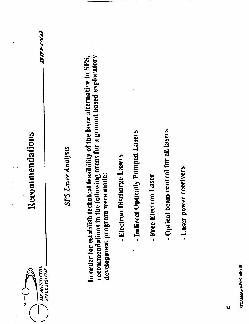
c_ s.
._ _
-,.._

0
"/4
5_
<
e.¢l
v


Qm
mm
t,..
om
,<
om
4_
L.--" _)
m
Dm
_m
0
uoi_:_oq uo!ss!msuvaj_ ao_od
.77
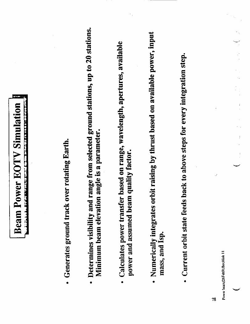
75

"I9

.."
LL
80

APPENDIX B
Minimum-Sized Lunar Campsite Analysis
D615-10031-1 81

,_,,_
eq
0
- • v,,,_
82

i-
C_oUmf

8_
ilqwl_

._ _ _i_!i_i_!i!ii!_!ii_!i_i_ii_i_i_i_iiii!_iii_i_i_i_iii_i_iii_iii_
i_i!_!_ii!i!i_ili!!!!_ii!i!ii!iiiii__:_i_!iiiii!ii!iiii_iii;iiiii_iiii_iii_iiiiiiiiiiiiiiiiiii!iiiiiiiiiiiiiii_Ii!_i_i!iii_ii!ii_;i!'i_i_i!_i;i_;_!i_i_i_i_i_i_i!!_'!_i_ii!i_i;_i_i_ii_i_i!!_i!.ii_i!i_i_!_i_i_J;_iiii_ii_!_i_!i_i_i_!i_i_i_!_ii
_i!_!_i.,i.i_i.i_.ii.i.._i.i_i.lii!._!_ii_i._.!,.i.i.i,i,i._i.__!_i.i!.i..i.!_i.i._.i..!_ii.i_i.i!.!.ii__i-ii_._-i-i_i_ili!i!!i!i!!i!ii!!iliiii_i!ti!!_i!iiiiii_ili!i!!iiiiii!iii!ili!iiiii!i!iii!iiiiiiiii!iii!iii!iiii_iii!!iiiiii!iiiiiiiiiiiiliiiiiiiiiiii!ii
m
0
85

r,_
E"=
=
f"t
°45
o_
o_
86
u_


0
8g

f l

90 _
r

v _
Q
r_J
EE0
Im
C_
0
!
LT.100 .._
I
O0 i* !
C_
C_
r_ _
.. _ "7,r._ rr_
<:_
u_
C_
A
C_ c_1
r_
c',1
c_
c,,i
o_
9]
O_
L1..
m=l

92
V


_ Pj
.'0.. o
_° _
94
_m

E
I
i
==
I
I.=,
Zl II_

96
u_
v
v

J
,._ t_
oN
°_
t_
97

.ln'l
,.o
98
vii
e_

J
imu
S
c_
C_
g
c_
_o
oO
r_
r_
o_
LL
99 "

0
100

j_J

Z,I
J
|0
0
1,1
n
INC_
qPn
_=o_
r_
lu
r_
_+
2
r_
I
!!
q_mb
m
_ r__mO
.._ I..,r_ 4.,
J
Igm_
°jm_
r_r_
"It"
I0"2
,_,.d

J
lj _J
i_ _i


/7
J

! " •
106
q_
c_C_
C_

N
107 N

108
V
e,


