
MEEZA MEEZA MV-2 SPE-5102-Performance CRAC and Downflow Unit Particular Specification: Part 2 Black
Document ref
SPE-5102Revision T0 August 2010

MEEZA MEEZA MV-2CRAC and Downflow Unit Specification
SPE-5102 Performance CRAC and Downflow Unit Particular Specification: Part 2 Ove Arup & Partners Ltd T0 08 August 2010
Contents
Page
1 Introduction 1
1.1 General 1
1.2 Tender Submission Deliverables 1
1.3 Project Description 2
2 Specific Preliminaries 3
2.1 Instruction for Tender 3
2.2 Contractor’s Responsibilities 3
3 Scope Of Works 4
3.1 Contractual Interfaces 5
3.2 Submittals 5
3.3 Operation and Maintenance Manuals 6
3.4 Health and Safety 7
3.5 Regulations and Standards 7
3.6 Identification Labels, Notices 8
3.7 General Testing & Commissioning 8
3.8 Training of Personnel 8
3.9 Handing Over 9
3.10 Service & Maintenance 9
3.11 Further Requirements 9
4 Particular Requirements 12
4.1 Operational Conditions 12
4.2 Plant 12
4.3 Life Expectancy 14
5 Controls and Instrumentation 15
5.1 General 15
5.2 Local Control Panel (LCP) 15
5.3 Human Machine Interface (HMI) 16
5.4 Functional Control 17
5.5 Control Valves and Actuators 18
5.6 Power Failure Restart 18
5.7 Electrical Interfaces 18
6 Testing and Commissioning 19
6.1 General Requirements 19
6.2 Factory Acceptance Tests (FAT) 23
6.3 Site Acceptance Tests (SATS) 24
6.4 Integrated Systems Testing 25
MEEZA MEEZA MV-2CRAC and Downflow Unit Specification
SPE-5102 Performance CRAC and Downflow Unit Particular Specification: Part 2 Ove Arup & Partners LtdT0 08 August 2010
7 Materials and Workmanship 26
7.1 General Requirements 26
7.2 Equipment Performance Ratings 26
7.3 CRAC and Downflow Unit Cabinet 26
7.4 Fans 27
7.5 Filters 27
7.6 Cooling Coils 27
7.7 Control Valves 27
Appendices
Appendix A
Equipment Data Sheets

MEEZA MEEZA MV-2CRAC and Downflow Unit Specification
SPE-5102-Performance CRAC and Downflow Unit Particular Specification Page 1 Ove Arup & Partners Ltd
T0 08 August 2010
1 Introduction
1.1 General
The following Tender specification details the requirements for the Computer Room Air
Conditioning (CRAC) units and downflow cooling units (referred to as Cooling units in this
specification where reference is being made to both) for the MEZZA MV-2 datacentre,
Qatar. The Supplier shall allow for the manufacture, supply, delivery to site, testing,
commissioning, and, setting to work of all equipment, preparation of all drawings, details
and design, record drawings and maintenance manuals for the whole works described
within this document and associated drawings.
The Supplier shall include, within the Tender, details of all variations from the equipment,
materials, installation methods, performance or operation as described in this Specification
and the associated drawings. Such variations shall be scheduled together at the front of the
Tender.
Should the Supplier be successful, the CRAC package shall be procured by the Contractor.
The Contractor is responsible for the complete and functional installation, and for
coordinating interfaces between the equipment supplied in accordance with this
specification and the rest of the works.
This document shall be read in conjunction will all other Contract Documents. Attention is
drawn to the following related documents:
• General Conditions of Contract
• CRAC and Downflow unit equipment data sheet appended to this specification
• Mechanical Services, Secondary Chilled Water Schematic, Critical W-55-801
• Secondary Chilled Water Schematics, Critical Back of House W-55-802 & 803
• Equipment Layout W-55-010
• CRAC and Downflow Unit Installation Detail W-59-900
• SPE-5100 - Outline Mechanical and Public Health Services Particular Specification: Part
2
• SPE-0000 – The General Specification : Part 1
The drawing listed are intended to assist the Supplier understand the project and shall not
be used for design purposes.
1.2 Tender Submission Deliverables
The following specific deliverables are required within the Tender submission in addition to
requirements outlined within the associated contract documents. These items will be
benchmarked against other suppliers during the Tender evaluations.
1.2.1 Technical Details of Proposal
The Supplier shall provide a summary of their technical proposal including detailed
equipment datasheets and an operation narrative.
The Supplier shall complete the technical datasheet found within Appendix A.
1.2.2 Cost Break Down
The Supplier shall provide a cost breakdown of his proposal with line items for the following
elements:
(i) Supply and delivery
(ii) Commissioning

MEEZA MEEZA MV-2CRAC and Downflow Unit Specification
SPE-5102-Performance CRAC and Downflow Unit Particular Specification Page 2 Ove Arup & Partners Ltd
T0 08 August 2010
(iii) FAT Tests
(iv) Training of personnel
(v) First Year Maintenance Contract including 24/7 call out with minimum of 4hrs response.
(vi) Recommended Spares (Include summary of recommended spare components)
1.2.3 Program of Works
The Supplier shall provide a program of works incorporating the following elements as a
minimum:
(i) Design Programme including issue dates to:
(a) The Contractor
(b) The Client / Designers (MEEZA / Arup)
(ii) Engineer’s Review of Documentation
(iii) Lead time for manufacture from placement of order
(iv) FAT test
(v) Transportation/delivery
(vi) Installation by Contractor
(vii) Commissioning
1.3 Project Description
MEEZA provide purpose built data centre facilities to provide outsourced solutions for
customers in the financial services, networks, enterprise and internet content markets
enabling customers to operate robust, scalable and highly available data-centres that can
be easily adapted to meet changing needs.
The new data centre shall be known as the ‘MV-2’ facility.

MEEZA MEEZA MV-2CRAC and Downflow Unit Specification
SPE-5102-Performance CRAC and Downflow Unit Particular Specification Page 3 Ove Arup & Partners Ltd
T0 08 August 2010
2 Specific Preliminaries
2.1 Instruction for Tender
Where the responsibilities of the Supplier are stated within this specification, the Supplier
shall make suitable allowance in terms of money, time and resources to be able to accept
these responsibilities and include the cost of this allowance within his Tender price. The
successful Supplier shall be expected to accept these responsibilities upon being awarded
the Contract.
The Tender shall provide capital costs for the manufacture, supply, delivery and testing and
commissioning of the cooling units including for all identified scope and his commercial
allowances. The Supplier shall provide separately identifiable costs for all ongoing planned
and unplanned maintenance of the cooling units and their controls.
2.2 Contractor’s Responsibilities
The Contractor shall be responsible for (but not limited to) the following:
• Management of delivery, offloading, installation (electrically and mechanically) and
integration of the Cooling units including connection of inlet and discharge ductwork to
fire walls and partitions as appropriate.
• Familiarisation with the technical content of the Cooling Unit package.
• Acquiring, collating and compiling any information from the Supplier required for
inclusion into the Contractor’s design documents, or to facilitate fully integrated
installation of the interfacing with other system elements. This shall include all
information required to support installation, production of installation drawings and the
resolution of interfaces with other system elements.
• Review and authorisation of the Supplier’s method statements for their works
• Review and authorisation of the Supplier’s Health and Safety plan for the works.
• Master scheduling of deliveries and works in collusion and agreement with the Supplier
• Removal of all construction waste from site.
The Supplier shall fully liaise, cooperate and co-ordinate with the Contractor in the
discharging of the above duties and make full allowance for resourcing these activities
within his Tender submission.

MEEZA MEEZA MV-2CRAC and Downflow Unit Specification
SPE-5102-Performance CRAC and Downflow Unit Particular Specification Page 4 Ove Arup & Partners Ltd
T0 08 August 2010
3 Scope Of Works
The Supplier shall be responsible for the design, supply to site, testing, commissioning,
documentation and handing over of the Cooling units, as per the requirements of the
Contract Documentation.
In addition to supply of the equipment, the Supplier shall also be responsible for the
following.
• The handling, physical protection, and delivery of all equipment as described in this
Specification.
• Full testing and commissioning and the production of associated reports and
documentation, including literature for incorporation within the project O&M manuals.
• Full technical documentation, submittals for all equipment and obtaining appropriate
technical review from the Client / Designer team.
• Comprehensive method statements including delivery, testing and commissioning taking
account of all risks associated with Health and Safety, for all testing and commissioning.
• The production of risk assessment prior to the commencement of any on site
commissioning work.
• All aspects of the design shall be liable for review by the Client / Designer and/or the
Engineer throughout the contract period. The Client / Designer and/or the Engineer
reserve the right to inspect the design and the supply works throughout the fabrication
of the system.
• The Supplier shall include for all documentation, items, accessories or apparatus which
may not have been specifically mentioned, but which are usual or necessary for
fabrication, offloading, handling during installation or protection of the Works necessary
to achieve and maintain the performance requirements and safe operation. Use of
particular headings, words or phrases denotes the complete supply of such products
supplied by the Supplier unless stated herein, unless otherwise specified.
MEEZA MEEZA MV-2CRAC and Downflow Unit Specification
SPE-5102-Performance CRAC and Downflow Unit Particular Specification Page 5 Ove Arup & Partners Ltd
T0 08 August 2010
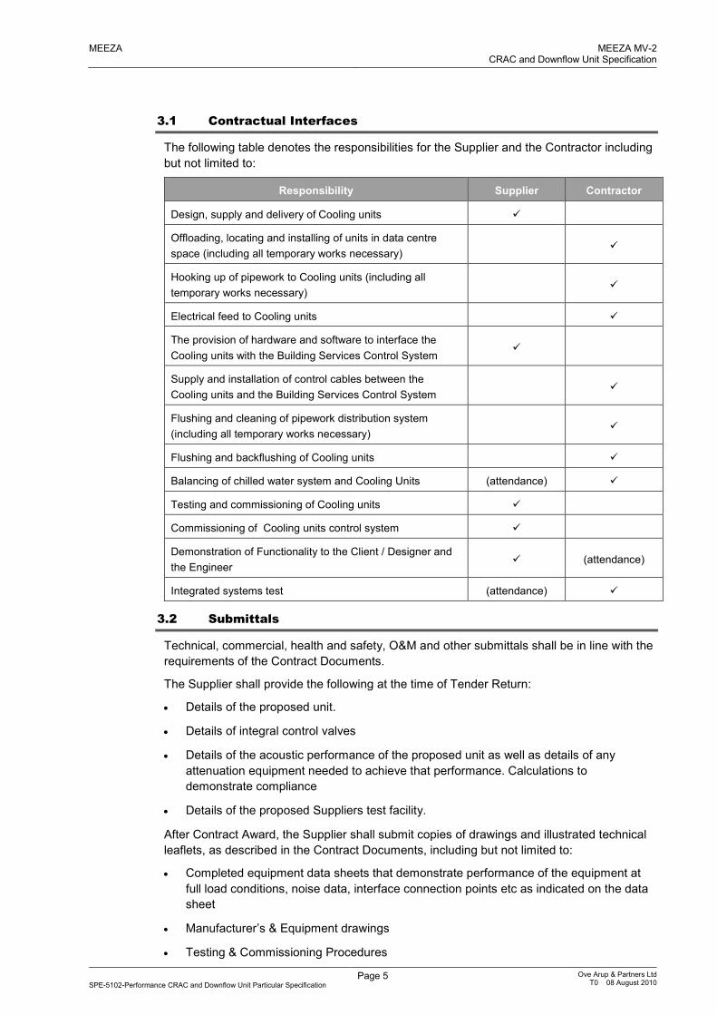
3.1 Contractual Interfaces
The following table denotes the responsibilities for the Supplier and the Contractor including
but not limited to:
Responsibility Supplier Contractor
Design, supply and delivery of Cooling units �
Offloading, locating and installing of units in data centre
space (including all temporary works necessary) �
Hooking up of pipework to Cooling units (including all
temporary works necessary) �
Electrical feed to Cooling units �
The provision of hardware and software to interface the
Cooling units with the Building Services Control System �
Supply and installation of control cables between the
Cooling units and the Building Services Control System �
Flushing and cleaning of pipework distribution system
(including all temporary works necessary) �
Flushing and backflushing of Cooling units �
Balancing of chilled water system and Cooling Units (attendance) �
Testing and commissioning of Cooling units �
Commissioning of Cooling units control system �
Demonstration of Functionality to the Client / Designer and
the Engineer � (attendance)
Integrated systems test (attendance) �
3.2 Submittals
Technical, commercial, health and safety, O&M and other submittals shall be in line with the
requirements of the Contract Documents.
The Supplier shall provide the following at the time of Tender Return:
• Details of the proposed unit.
• Details of integral control valves
• Details of the acoustic performance of the proposed unit as well as details of any
attenuation equipment needed to achieve that performance. Calculations to
demonstrate compliance
• Details of the proposed Suppliers test facility.
After Contract Award, the Supplier shall submit copies of drawings and illustrated technical
leaflets, as described in the Contract Documents, including but not limited to:
• Completed equipment data sheets that demonstrate performance of the equipment at
full load conditions, noise data, interface connection points etc as indicated on the data
sheet
• Manufacturer’s & Equipment drawings
• Testing & Commissioning Procedures

MEEZA MEEZA MV-2CRAC and Downflow Unit Specification
SPE-5102-Performance CRAC and Downflow Unit Particular Specification Page 6 Ove Arup & Partners Ltd
T0 08 August 2010
• Operation & Maintenance Manuals
• Controls narrative for the equipment
• Details of control provisions including schedule of I/O available to the BMS and the
native control protocol of the equipment and any unit non-proprietary unit controller
Rating tables, physical data and capacity data for the selection of equipment shall be
submitted to demonstrate a range of operating conditions. Such information shall be based
on Suppliers' test results for the equipment to be supplied.
Performance curves and tables shall be submitted to define the plant selection including:
• Specified duty.
• 10% overload condition.
Published pressure drop values for coils shall have been determined from type tests. Type
test data shall be available for examination.
A list of simulated conditions designed to check operation of all safety devices during
performance testing, commissioning and testing shall be provided.
Fouling factors for the coils used shall be stated by the Supplier, and shall be appropriate for
the system employed.
The Supplier shall submit a full set of control panel drawings for comment prior to
manufacture which shall include but not be limited to:
• Fascia layout
• Back plate
• Internal wiring diagrams including cable identification
• External loop diagrams
3.3 Operation and Maintenance Manuals
The Supplier shall prepare Operation and Maintenance manuals covering and including the
information detailed below. Textual documents shall be provided in Microsoft Word or
Microsoft Excel and all drawings shall be provided in AutoCAD ‘dwg’ format. Additionally, all
documents and drawings shall be provided in Adobe ‘pdf’ format.
The operation and maintenance manuals shall as a minimum contain the following:
(i) Description of the systems and all the components with specification of manufacture,
model type no., supplier, etc.
(ii) Record drawings.
(iii) Brochure/catalogue sheet with complete technical data, dimensions, instructions for
dismantling and mantling, etc.
(iv) Full operating instructions.
(v) Maintenance manuals setting out all regular, planned, scheduled and periodic
maintenance, cleaning instructions etc. and routine inspections necessary to maintain
the equipment and installation in peak condition.
The latter information shall be compiled in tabular form as follows:
Plant item/weekly/monthly/quarterly/six monthly/annually/remarks.
A schedule of maintenance and cleaning methods and operations of any non plant related
items, including cleaning agents to be used and methods to be adopted.

MEEZA MEEZA MV-2CRAC and Downflow Unit Specification
SPE-5102-Performance CRAC and Downflow Unit Particular Specification Page 7 Ove Arup & Partners Ltd
T0 08 August 2010
Detailed recommendations as to the preventive maintenance frequency and procedures,
including related health and safety procedures, which shall be adopted by the Client /
Designer to ensure the safe and efficient operation of the systems.
Lubrication programmes for all lubricated items of plant and equipment.
A list of consumable items and special tools it is recommended that the Client has in stock.
A list of recommended ”running spares” required, being those items subject to wear or
deterioration and which may involve the Client in extended deliveries when replacements
are required at some future date.
Procedures for fault diagnosis.
Emergency procedures.
The operation and maintenance manuals shall be prepared in English. The manuals shall
be contained in A4 size, plastic-covered, loose leaf, four ring binders with stiff covers, each
indexed, divided and appropriately cover-titled.
The Supplier shall make a set of temporary manuals available at commencement of
commissioning for comments by the Client / Designer. These shall be of the same format as
the final manuals with temporary insertions for items which cannot be finalised until after the
works are commissioned and performance tested.
The Supplier shall issue this documentation to the Contractor for master editing and overall
co-ordination of all other O&M manuals from other works.
The Contractor shall issue the final co-ordinated operation and maintenance manuals and
shall submit two hard copies in addition to a complete digital submission of all Microsoft
Word, Microsoft Excel, AutoCAD ‘dwg’ and Adobe ‘pdf’ files.
3.4 Health and Safety
The Supplier shall comply with all applicable health and safety regulations. The Supplier
shall identify the risks involved in the installation and operation of the plant and equipment
described in this specification. The Supplier shall provide detailed Method Statements to the
Contractor as detailed in the Testing and Commissioning Section.
The Supplier shall make the Contractor aware of any health and safety issues relating to the
installation of the chillers.
3.5 Regulations and Standards
All equipment and installations shall comply with all relevant statutory instruments and
regulations.
The design, specification and installation of all equipment is required to comply where
applicable with the following publications and supplements:
• Qatar National Construction Specification (QCS)
• QGWEC Regulations
• British Standards
• European Standards
• ASHRAE
• CIBSE
• BSRIA

MEEZA MEEZA MV-2CRAC and Downflow Unit Specification
SPE-5102-Performance CRAC and Downflow Unit Particular Specification Page 8 Ove Arup & Partners Ltd
T0 08 August 2010
3.6 Identification Labels, Notices
All equipment, units and control panel designations shall be identified by means of suitably
engraved plastic labels positively secured by means of screws.
Warning notices shall be provided and fitted in accordance with relevant regulations and
best practice.
3.7 General Testing & Commissioning
The Supplier shall carry out full works testing of one Cooling units as described within this
specification, the Equipment Data Sheet and the rest of the Contract Documents.
The Supplier shall ensure that all testing is carried out in accordance with the equipment
manufacturer’s guidelines and recommendations such that the equipment warranties remain
valid.
The Supplier shall include for site testing of all units to demonstrate functionality (including a
breakdown of costs, time allowed etc and a day rate for additional testing).
The Supplier shall include for 3 days of site attendance and assistance during the integrated
systems test (including a breakdown of costs, time allowed etc and a day rate for additional
attendance).
The Supplier shall be responsible for the testing of all his equipment to the satisfaction of
the Contractor.
The Supplier shall develop a commissioning programme with the Contractor to ensure that
all systems are approved for handover in accordance with the project schedule.
The Supplier shall use qualified personnel to carry out the commissioning whether those
people be in-house personnel or external consultants.
The deliverables and responsibilities are discussed in more detail in the specific Testing and
Commissioning section of this specification.
3.8 Training of Personnel
The Supplier shall provide for training of the Client’s personnel in the use of the installed
equipment. This shall take place before or during the commissioning of the plant. Timing
shall be agreed with the Client and the Contractor prior to the training taking place. The
Supplier shall allow for training a minimum of six personnel.
The training programme shall include:
• Introduction to and description of the system (class room based)
• Introduction to and description of the system (site based)
• Starting procedures
• Stopping procedures
• Operation of all safety devices
• Fault analysis
• Routine maintenance (daily, weekly, monthly, yearly)
• Preventative maintenance
• Cleaning procedure
MEEZA MEEZA MV-2CRAC and Downflow Unit Specification
SPE-5102-Performance CRAC and Downflow Unit Particular Specification Page 9 Ove Arup & Partners Ltd
T0 08 August 2010
3.9 Handing Over
Handing over shall not take place until:
• The equipment has been tested and commissioned to the satisfaction of the Contractor,
the Client / Designer and the Engineer
• Possible defects made good
• CE – Marking has been carried out
• The documentation required including any approvals from authorities has been handed
over to the Client / Designer and/or the Engineer
• The operation and maintenance manuals, including record drawings, have been handed
over to and formally accepted in writing by the Client / Designer and/or the Engineer.
3.10 Service & Maintenance
The Supplier shall provide details for a yearly service and maintenance agreement contract.
This shall include:
• Price for yearly, three yearly and five yearly agreement
• Availability and numbers of local service engineers
• Availability of replacement parts
• List of replacement parts
• Typical response times
3.11 Further Requirements
3.11.1 Preparation for Transportation
Equipment shall be designed and fabricated to facilitate the handling, loading and
installation process, and include suitable lifting lugs or other appurtenances or features
required for lifting, handling and installation.
Each crate, box, carton, container or package shall be clearly marked or tagged with the
designated equipment name and identification number and Purchase Order number. Tags
if used shall not be less than 38 mm diameter, with stainless steel ties. All other markings
shall be stencilled.
All finished rubbing surfaces, which are not assembled in the shop, shall be adequately
protected during shipment by wrapping with heavy-duty plastic sheeting or canvas or other
means, which shall be secured by wooden batts securely wired together.
Exposed machined working parts shall be rust inhibited and wrapped for shipment.
Flanged connections shall have blind hardwood flanges bolted onto the flanges to protect
the flanges from abuse and the equipment interior from contamination during shipment.
Screwed end connections shall be capped. Other openings in the equipment shall be
plugged.
Moving parts shall be securely blocked to prevent damage during transport. All material
used to block moving parts shall be tagged and marked to ensure removal before start-up.
Machined surfaces and flange faces shall be coated with heavy rust preventative grease.
All coupling threads shall be coated with tallow base waterproof lubricant to prevent galling
in use and corrosion during shipment and storage.

MEEZA MEEZA MV-2CRAC and Downflow Unit Specification
SPE-5102-Performance CRAC and Downflow Unit Particular Specification Page 10 Ove Arup & Partners Ltd
T0 08 August 2010
The Supplier shall issue a report on damages or shortages after checkout on site of each
shipment. All material delivered shall be subject to the Supplier inspection and rejection.
3.11.2 General Design Criteria
In addition to the fundamental requirements of performance and quality outlined in the
Specifications, the design shall take into consideration ease of maintenance, good
housekeeping and safety.
Adequate adjustment shall be provided to compensate for wear. Replacement of parts shall
involve a minimum of disassembly. Access shall be reasonable and safe.
In addition to the forces imposed by the function of the equipment, the design shall take into
account reasonable forces imposed by personnel and equipment used in servicing.
All materials and equipment shall be selected with regard to standardisation and availability
of spare parts and service.
3.11.3 Shop Fabrication and Assembly
Methods and equipment employed by the Supplier for shop fabrication shall ensure first
class workmanship.
All purchased components shall be selected and installed in accordance with the
manufacturer's recommendations for their application.
All components shall be thoroughly inspected for dimensional accuracy, surface finish, etc.
before assembly.
3.11.4 Inspection
The Client / Designer and/or the Engineer reserve the right to inspect the equipment while it
is being manufactured. The Supplier shall provide free access to his plant and facilities at
any time and assist the inspectors to carry out their duties.
The Supplier shall notify the Client / Designer and/or the Engineer as necessary to allow, at
his option, inspection at the time the equipment fabrication is 100% complete, and/or prior to
scheduled testing so that each may inspect the equipment and witness the standard
production tests.
Inspection at the Supplier's plant shall not relieve the Supplier from any responsibility in
regard to imperfect material or workmanship and the necessity for replacing defective
material or workmanship which does not fulfil the requirements of the Contract Documents.
The acceptance of, or failure to inspect, any material or finished parts by the Supplier or
inspectors shall not prohibit subsequent rejection if found defective. Rejected material and
workmanship shall be replaced or made good by the Supplier.
It is the responsibility of the Supplier to schedule and maintain adequate shop inspection
during the fabrication of the equipment.
3.11.5 Maintenance Tools
The Supplier shall provide three sets of all special tools required for erecting, testing,
operating, maintenance or dismantling of the equipment supplied. Each set of tools shall be
provided in a steel box fitted with a padlock. The tools shall not be used during the erection
or commissioning of the equipment.
Triplicate keys shall be provided for all locks supplied in this package. One master key shall
be provided in addition to the standard keys.
3.11.6 Spares and Consumables
The Supplier shall provide three copies of a comprehensive priced list of spares for all
equipment and components supplied under this package.
The Supplier shall recommend which spares and consumables he considers should be held
to cover:

MEEZA MEEZA MV-2CRAC and Downflow Unit Specification
SPE-5102-Performance CRAC and Downflow Unit Particular Specification Page 11 Ove Arup & Partners Ltd
T0 08 August 2010
• The first two years of operation of the equipment supplied
• Long term operation
All spares shall be subjected to the provisions of the Contract Documentation.
The Supplier shall ensure that adequate spare parts are held available in his stores to
prevent delays in commissioning the equipment.
The Supplier shall confirm the location and time-to-site of nearest stocking dispensary and
nearest qualified service/repair personnel.
MEEZA MEEZA MV-2CRAC and Downflow Unit Specification
SPE-5102-Performance CRAC and Downflow Unit Particular Specification Page 12 Ove Arup & Partners Ltd
T0 08 August 2010
4 Particular Requirements
4.1 Operational Conditions
4.1.1 Operating Conditions
The CRAC units will be located within the data centre space. The general operating
temperatures shall be as stated in the Equipment Data Sheets. However the Supplier shall
ensure that the CRAC units shall function satisfactorily if the temperature and humidity are
subject to short-term excursions.
Downflow cooling units are located in service corridors and other conditioned plant rooms,
internal electrical plant rooms and network termination rooms as well as the BMS control
room, burn in room and bunker room.
All equipment should be rated to operate at 50deg.C ambient (i.e. start-up/site storage
condition) without damage.
4.1.2 Operational Hours
The facility shall operate continuously 24 hours per day, seven days per week without
maintenance shut down periods.
4.2 Plant
All CRAC units shall have the following unless outlined as a specific requirement below:
• Factory fitted controllers that can achieve the functionality described in Section 5 of this
document. If the Supplier standard controller cannot achieve the required functionality
then a unit supplied by the BMS Contractor shall be used. This shall be programmed by
the Supplier, fitted in the factory and be tested as part of the FAT. The Supplier shall
identify the need to use a controller supplied by the BMS Contractor at the time of
Tender return.
• Plug type fans with EC motors – capable of operating at variable speed
• Minimum of 3 binder points providing the ability to measure pressure drop across the
coil and across the control valve
• Anti-vibration hose type connections and base frames and “all other accessories
highlighted on data sheets” for CRAC units.
• Include a steelwork stand to mount the unit level with the raised floor (950 mm) and
support adjacent floor tiles. To be coordinated prior to manufacture.
• Inlet and outlet ductwork for units as required depending on the installation
configuration.
• Include an integral backflow damper to prevent reverse airflow through the unit should it
be off or fail.
• Include an integral automatic transfer switch to allow power feed from two no. diverse
supplies.
• A combined differential pressure and 2 port control valve, factory fitted by the CRAC
manufacturer and in place for the FAT and upon delivery to site.
All downflow cooling units shall have the following unless outlined as a specific requirement
below
• Factory fitted controllers that can achieve the functionality described in Section 5 of this
document. If the Supplier standard controller cannot achieve the required functionality
then a unit supplied by the BMS Contractor shall be used. This shall be programmed by
the Supplier, fitted in the factory and be tested as part of the FAT. The Supplier shall

MEEZA MEEZA MV-2CRAC and Downflow Unit Specification
SPE-5102-Performance CRAC and Downflow Unit Particular Specification Page 13 Ove Arup & Partners Ltd
T0 08 August 2010
identify the need to use a controller supplied by the BMS Contractor at the time of
Tender return.
• Plug type fans with EC motors – capable of operating at variable speed
• Minimum of 3 binder points providing the ability to measure pressure drop across the
coil and across the control valve
• Anti-vibration hose type connections and all other accessories highlighted on data
sheets downflow cooling units.
• Include an integral automatic transfer switch to allow power feed from two no. diverse
supplies.
• Include a steelwork stand to mount the unit level with the raised floor (950 mm) and
support adjacent floor tiles, or installation on the plantroom floor depending on the
specific unit requirements identified in the data sheet. To be coordinated prior to
manufacture.
• Inlet and outlet ductwork for units as required depending on the installation
configuration.
• A combined differential pressure and 2 port control valve, factory fitted by the CRAC
manufacturer and in place for the FAT and upon delivery to site.
4.2.1 Support Frame and Ducting
The CRAC and downflow units shall be provided with support frames and, where necessary,
inlet and outlet ductwork, to suit the specific installation requirements, so a number of
variations are needed. These include the following:
CRAC Units
• Frame standing with free discharge to the floor plenum,
• Frame standing, with the discharge ducted (ie frame enclosed on three sides, and
front discharge ducted to the adjacent underfloor plenum) and ducted return.
Downflow Units
• Free standing with discharge at low level (for applications where unit is located
within the plantroom/ancillary area it is cooling)
• Free standing with ducted inlet and discharge (for applications where unit is external
to the plantroom it is cooling)
• Frame standing with discharge to the floor plenum (for applications where the unit is
cooling a service corridor).
All frame standing units are for use in a raised floor application. The height of the stand
shall be coordinated with the local raised floor height by the Contractor, and be adjustable to
allow for the floor slab tolerance. The frame shall include provision to support surrounding
floor tiles.
The number of each type of support / ducting arrangement is included in the equipment data
sheets.
4.2.2 Specific Requirements
Type specific requirements for CRAC units are outlined below:
• Fans speed shall be modulated according to either floor void pressure using a pressure
signal provided to the unit by the BMS or by return air temperature – selectable at the
CRAC HMI.
• The combined differential pressure and 2 port valve shall be modulated according to
either supply air temperature or return air temperature – selectable at the HMI.
MEEZA MEEZA MV-2CRAC and Downflow Unit Specification
SPE-5102-Performance CRAC and Downflow Unit Particular Specification Page 14 Ove Arup & Partners Ltd
T0 08 August 2010
• When within the dead band, the CRAC shall modulate the 2 port valve to maintain a 6
°C temperature difference between the supply and demand chilled water temperatures.
4.3 Life Expectancy
Cooling unit cases and components shall be constructed to achieve a guaranteed service
life to first major maintenance of 15 years and design life in excess of 25 years.
A guarantee and details of the materials, construction and protection systems proposed
shall be submitted.

MEEZA MEEZA MV-2CRAC and Downflow Unit Specification
SPE-5102-Performance CRAC and Downflow Unit Particular Specification Page 15 Ove Arup & Partners Ltd
T0 08 August 2010
5 Controls and Instrumentation
5.1 General
Each CRAC and downflow unit shall be provided as a composite unit and be provided with a
standalone onboard controls system which shall be connected to the BMS network by the
Contractor.
If the CRAC and downflow manufacturer’s standard controller cannot achieve the required
functionality then a different manufacturer’s unit controller can be supplied. The Cooling unit
manufacture shall detail which controller they intend to provide and submit a technical data
at the time of tender. The Cooling unit controller shall have ModBus or BacNet serial data
interface capabilities without the need to use a third party device, “black box” or protocol
convertors shall not be accepted.
The CRAC and downflow unit controller shall be fitted in the factory and be tested as part of
the FAT.
All timers, set points, parameters etc, shall be fully adjustable with the final values being set
during commissioning.
The unit shall be able to operate continuously with automatic power fail restart without
manual intervention.
The fan speed shall be set within defined limits within the Cooling unit controllers which shall
operate under 2 different parameters which shall be:
• A reset signal from the BMS within the defined parameters set within the Cooling
controller
• Each floor standing free discharge to floor void Cooling unit shall be provided with 2
floor mounted pressure sensors
All alarms shall be masked during start up or when shut down.
Consequential alarms shall be masked.
All alarms shall be configured to be fail safe i.e. open on alarm not close on alarm.
All temperature transmitters shall be pocket mounted PA00 with head mounted 4-20 mA
transmitters.
The Supplier shall provide all inputs and outputs as per the Equipment Data Sheet.
5.2 Local Control Panel (LCP)
An IP54 LCP shall be provided as a pre-wired composite unit that shall include but not be
limited to:
• Load break door interlocked electrical isolator
• All components shall comply with IP2X
• All internal wiring shall be colour coded, ferruled and end crimped
• All wiring shall be housed in slotted plastic trunking which shall not exceed 50%
capacity
• All external wiring shall be connected into Klippon type disconnect terminals with a
separate earth terminal for all analogue devices. External wiring shall not be run through
the control panel so location of the disconnect terminals must be local to the cable entry
point.
• A separate section to house the Cooling unit controller
MEEZA MEEZA MV-2CRAC and Downflow Unit Specification
SPE-5102-Performance CRAC and Downflow Unit Particular Specification Page 16 Ove Arup & Partners Ltd
T0 08 August 2010
• The microprocessor controller and any other control device as required by the
manufacturer
• Fuses, MCB’s, relays and all safety devices
• All external wiring shall be terminated through purpose made cable glands
5.3 Human Machine Interface (HMI)
The Human Machine Interface shall provide the following functionality but not be limited to:
• Indication of all parameters specified
• A minimum of three levels of access
� View only
� Change set points, select the unit to reset alarms, adjust assigned parameters
which shall be password protected.
� Service engineer’s access which shall be password protected.
• An automatic logout facility.
• A graphical user interface with navigation to alarm logs, set points, equipment status
etc.
The information and facilities available at the Cooling unit HMIs shall include but not be
limited to the following information:
CRAC units
• Running
• Critical alarms
• Non-critical alarms
• Alarm history
• Ability to select
� DEFAULT - Control Chilled water 2 port valve on supply air temperature / Fan
speed on signal from BMS or floor mounted pressure sensors
� OR - Control Chilled water 2 port valve on return air temperature / Fan speed on
signal from BMS or floor mounted pressure sensors
� OR - Control Chilled water 2 port valve on supply air temperature / Fan speed on
return air temperature
• Temperature set point adjustment
• Temperature set point
• Supply air temperature
• Return air temperature
• Chilled water supply temperature
• Chilled water control valve position
• Chilled water control valve feedback position
• Fan speed
• Fan speed adjustable set point between pre-set parameters
• Hours run
MEEZA MEEZA MV-2CRAC and Downflow Unit Specification
SPE-5102-Performance CRAC and Downflow Unit Particular Specification Page 17 Ove Arup & Partners Ltd
T0 08 August 2010
• Fault reset
• Filter change alarm/filter differential pressure reading
• Floor void differential pressure reading
Interface with the BMS
The CRAC unit controllers shall provide the following points which shall be “mapped” back
to BMS over ModBus or BacNet:
Downflow Units
• Running
• Critical alarms
• Non-critical alarms
• Controlling 2 port control valve on
� Supply air temperature
• Controlling fan speed on
� Return air temperature
• Temperature set point
• Supply air temperature
• Return air temperature
• Chilled water supply temperature
• Chilled water control valve position as an output
• Chilled water control valve position feedback position
• Fan speed
• Unit failed reset
• Filter change alarm/filter differential pressure reading
5.4 Functional Control
5.4.1 CRAC Units
The unit controller shall modulate the 2 port control valve actuator to maintain a pre-
determined set point which shall be based upon either supply air or return air temperature.
When the chilled water temperature difference across the cooling coil drops below 6°C for a
period of 5 minutes, the CRAC controller shall reset the Proportional / Integral Loop of the
chilled water valve to re-establish the 6 °C differential.
The EC fan controller shall modulate the fans, between pre-determined set points (which
shall be set within the CRAC controller), based on a signal from the BMS, the floor mounted
pressure sensors or to maintain a set return air temperature. The controller shall prevent the
ability to operate both the control valve position and fan speed on return air temperature.
The CRAC units are supplied from a DRUPS, so electrical power shall be maintained in the
event of an interruption to the mains power. However, the units shall have the capability of
restarting without human interaction if the electrical power supply is interrupted. This shall
be tested as part of the FAT.
5.4.2 Downflow Cooling Units
The unit controller shall modulate the 2 port control valve actuator to maintain a pre-
determined set point which shall be based upon supply air temperature. The EC fan
controller shall modulate the fans based upon return air temperature.

MEEZA MEEZA MV-2CRAC and Downflow Unit Specification
SPE-5102-Performance CRAC and Downflow Unit Particular Specification Page 18 Ove Arup & Partners Ltd
T0 08 August 2010
When the chilled water temperature difference across the coil drops below 6°C, for a period
of 5 minutes, the controller shall reset the Proportional / Integral Loop of the chilled water
valve to re-establish the 6 °C differential
The CRAC units are supplied from a DRUPS, so electrical power shall be maintained in the
event of an interruption to the mains power. However, the units shall have the capability of
restarting without human interaction if the electrical power supply is interrupted. This shall
be tested as part of the FAT.
5.5 Control Valves and Actuators
The control valve and actuators shall comply with the Materials and Workmanship section.
5.6 Power Failure Restart
Following a power failure the valve shall not close (drive open/close type) to ensure the
shortest time to re-establishing full cooling duty.
The Supplier shall give details of the time taken for the unit to return to full duty (100% fan
speed) following a power failure. This shall include time taken for the controller to reboot. It
is permissible to include a relay in order to establish power to the fan before the controller is
rebooted. This relay shall drop out after a period (no longer than 5 minutes) and return fan
speed control to the controller.
5.7 Electrical Interfaces
The bulk supply is to feed fans and controls. The Supplier shall provide details of electrical
supply requirements within his submission.
The Supplier shall provide details regarding the maximum permissible cable termination size
for the electrical supply. The supply shall be bottom entry to the unit.
All electrical components and installation methods shall comply with the local authority
standards and legal requirements.

MEEZA MEEZA MV-2CRAC and Downflow Unit Specification
SPE-5102-Performance CRAC and Downflow Unit Particular Specification Page 19 Ove Arup & Partners Ltd
T0 08 August 2010
6 Testing and Commissioning
6.1 General Requirements
The Works shall allow for the co-ordination, testing and commissioning of part (or all) of the
works as set out in the Commissioning Responsibilities Matrix below.
Commissioning Responsibilities Matrix
�
A
Responsible for Implementation
Provides assistance/attendance
Note Contractor shall be responsible for programming and co-
ordination of all commissioning works. The Supplier shall carry
out his works and provide attendance as required
Activity Supplier Contractor
Factory Acceptance Tests � A
Co-ordination meetings to confirm
installation interfaces and
programme
A �
Commissioning meetings to confirm
activities, responsibilities and
programme
A �
Pre-commissioning � A
Commissioning � A
Site Acceptance Tests � A
Demonstration of Functionality to the
Client / Designer and the Engineer
� A
Integrated System Test A �
Client Training � A
The Supplier shall attend site for the purposes of co-ordination, planning and
implementation of these works as directed by the Contractor.
6.1.1 Documentation and Certificates
The Supplier shall submit Testing and Commissioning and Performance Testing method
statements, data and manuals as required by the Contract Documents and as necessary to
allow the Contractor to plan, co-ordinate and implement the associated works as detailed
below.
For on-site activities, these shall be separately identified.
The Supplier shall provide all necessary and appropriate documentation to the Contractor to
allow him to compile the documentation set out below.
The Supplier shall agree procedures for notices, witnessing, reporting and recording tests
with all parties involved including Local Authorities and Statutory Undertakings, prior to the
commencement of the works. The Supplier shall provide all necessary and appropriate
assistance to the Contractor.
The Supplier shall submit copies of the formal test certificates signed by the Supplier and
the Contractor’s representative not later than 3 days after completion of successful tests.
MEEZA MEEZA MV-2CRAC and Downflow Unit Specification
SPE-5102-Performance CRAC and Downflow Unit Particular Specification Page 20 Ove Arup & Partners Ltd
T0 08 August 2010
6.1.2 Instruments and Equipment for Testing
The Supplier shall supply, check, recalibrate whenever necessary and maintain in good
working order all instruments and equipment for setting out, measurements, gauging,
inspection, commissioning and performance testing whether they are specifically called for
or implied by the Contract Documents.
All such instruments and equipment shall be adequate for the purpose and shall satisfy the
purposes and accuracy's required by the Contract Documents.
All instruments and equipment shall remain the property of the Supplier.
6.1.3 Provision of Staff
The Supplier shall provide all necessary staff with the relevant skills and competence for all
inspection, testing, commissioning and performance testing.
6.1.4 Costs of Tests
The Supplier shall bear the costs for all parts of all tests as described in this document.
6.1.5 Notice to Client / Designer
The Supplier shall give at least seven days' notice to the Client / Designer and/or the
Engineer of any commissioning or testing to be carried out to enable the Client / Designer
and/or the Engineer to witness all or any of such tests, etc.
6.1.6 Commissioning and Performance Testing Specifications and Manuals
The Supplier shall prepare and submit a set of testing and commissioning specifications and
manuals. These shall be prepared in draft for review and comment by the Contractor at
least 4 weeks prior to any testing, commissioning and performance testing activities. The
manuals shall include, but need not be limited to:
• Factory, off-site and on-site testing, commissioning, acceptance testing,
demonstrations, Client training and performance testing Method Statements and activity
check list.
• Complete set of proposed test/commission forms, pro formas etc.
The Supplier shall produce this Specification incorporating all necessary data, documents
and the like. It is essential that this document represents a comprehensive approach for the
complete Works and associated interfaces.
Commissioning Method Statements shall be based on the current Codes of Practice and all
applicable Standards. They shall describe the exact method that the Supplier and the
Contractor shall adopt to commission an item of equipment. The Method Statements shall
be approved by the Client / Designer and/or the Engineer prior to any commissioning activity
taking place.
6.1.7 Commissioning Manual
This document shall provide an updated version of the equipment Commissioning and
Performance Testing Specification including a comprehensive set of all testing and
commissioning forms, pro-formers, certificates and the like, duly completed and witnessed.
Test Certificates, which shall contain the following minimum information:
(a) System Identification
(b) Date of Test
(c) Design Date
(d) Individual Equipment Identifications
(e) Reference Number of Tests
(f) Referenced Test Procedure and/or Method Statement
(g) Reference QA/QC Procedure

MEEZA MEEZA MV-2CRAC and Downflow Unit Specification
SPE-5102-Performance CRAC and Downflow Unit Particular Specification Page 21 Ove Arup & Partners Ltd
T0 08 August 2010
The commissioning manuals shall contain the following sections:
(a) Systems Schedules
(b) System Test and Commission Specifications
(c) A record of all tests carried out (including all testing recorded on Test Certificates)
(d) Drawings and diagrams cross-referenced with the test records
(e) Record of instrumentation used, together with current calibration certificates.
At the completion of all testing and commissioning the Supplier shall provide the completed
testing and commissioning manuals in both hard copy as agreed with the Client / Designer
and/or the Engineer and electronic format compatible with Microsoft Word, Excel or as
otherwise directed by the Client / Designer and/or the Engineer. The electronic transmittal
shall be on read/write CD. Two sets of disks shall be handed over: one Master and one
working copy. A strict software configuration control shall be enforced.
6.1.8 Inspection and Testing Certificates
6.1.8.1 Supply Works Test Certificates
Works tests certificates shall include, whenever applicable, full information to enable the
item tested to be identified, such as project title, Supplier's name, manufacturer's nameplate
or serial numbers, the location in the Supply Works and the delivery or batch which the
sample represents.
6.1.8.2 Inspection and Testing Records
The Supplier shall maintain records of all inspections, and testing performed to substantiate
conformity with the Contract Documents including those carried out by the Supplier and/or
third party testing agencies, together with manufacturers' or Suppliers’ certificates of test.
All records shall be retained on site and made available to the Client / Designer and/or the
Engineer on request. On completion of the Works all records shall be handed over to the
Client / Designer and/or the Engineer unless otherwise directed.
These records shall include, as appropriate, but not be limited to, project title, Supplier's
name, the identification of the element, item, batch or lot, the nature and number of the
observations and tests, the dates of testing, the name and signature of the person
responsible for the testing, the number and type of deficiencies found, and details of any
corrective action taken.
Any record, which indicates that any part of the Works inspected or tested does not comply
with the Contract Documents, shall be submitted without delay in order that the Supplier's
proposals for rectification may be assessed.
6.1.9 Control of Time
The Supplier shall co-operate with any other Suppliers and sub-contractors who may be
working on, adjacent to, or connected with the Supply Works. In positions where
construction Works and installations are adjacent to or in the vicinity of the Supply Works,
co-operate in every respect with the Contractor to determine the most suitable sequence of
installation.
6.1.10 Instruction of the Client’s Staff
Prior to commissioning of the installation, the Client shall be appointing operating and
maintenance staff or maintenance contractor to undertake the operation and maintenance of
the Works. The Supplier shall provide assistance to the Client’s staff during the course of
the installation to explain the purpose and function of the Works. This assistance shall be
planned and organised by the Contractor. The Supplier shall allow for 8 people training for a
period of 2 days.
The instruction shall cover the day to day running of the plant and systems. The location
and function of all items listed on the Record Schedules shall be explained and the

MEEZA MEEZA MV-2CRAC and Downflow Unit Specification
SPE-5102-Performance CRAC and Downflow Unit Particular Specification Page 22 Ove Arup & Partners Ltd
T0 08 August 2010
procedures given in the Operating and Maintenance Manuals for starting up, shutting down,
isolating sections, emergency procedures, etc, shall be comprehensively explained and
demonstrated to the Client’s satisfaction. Such training periods shall not coincide with any
other testing, commissioning or continuous run periods.
6.1.11 General Inspection
The Supplier shall test each plant item as specified herein and as required by British Codes
and by applicable Insurance Agencies. Tests shall be witnessed by all required parties and
written certification of same furnished to the Client / Designer. The Supplier shall co-ordinate
all testing and commissioning with the Contractor.
Inspections and tests shall be carried out in accordance with specified or approved
procedures and the results shall be judged in accordance with the specified Standards or
other agreed criteria including criteria defined in the Specification.
6.1.11.1 Statutory Approval Testing
The Supplier shall be responsible for ensuring that all tests and approvals required by
Statutory Authorities are duly performed by an approved Insurance Authority and the
relevant approval documents issued, free of charge, to the Contractor. The name of the
Insurance Authority shall be stated by the Supplier for approval by the Contractor \at the
time of Tender. The Contractor may nominate an Insurance Authority in lieu of the
Supplier's Insurance Authority.
6.1.11.2 Pre-commissioning, Setting to Work
Following the completion of installation, all equipment shall be pre-commissioned, set to
work and commissioned. The Supplier shall conduct these tests to ensure the safe and
correct setting to work of the equipment supplied under the Contract.
The Supplier shall detail the tests required which shall include but not be limited to the
following:
• Check all electrical connections to ensure that they are correct
• Inspect the Contractor’s and other Sub-contractor's electrical test records to ensure that
the Equipment is safe to operate.
• Carry out any further electrical tests necessary to ensure the Equipment is in a safe and
satisfactory condition to operate.
• Check operation of all safety devices
• Check all pipework connections (chilled water and condensate)
• Check the installation of valves, mountings, pipe and fittings
• Check lubrication
• Check rotation of drives
• Check and confirm power consumption of all electrical equipment (e.g. fans, pumps,
heaters etc.)
• Carry out short running tests on all items sufficient to demonstrate the general operation
of the Equipment and the operation of controls, control valves, instruments etc.
• Carry out any field testing of the installed works control system and interface with the
BMS.
• Preliminary noise level tests
• Tests required by the Insurance Authority and Statutory Authorities
Submit a written report of satisfactory completion of each phase of work to the Contractor.

MEEZA MEEZA MV-2CRAC and Downflow Unit Specification
SPE-5102-Performance CRAC and Downflow Unit Particular Specification Page 23 Ove Arup & Partners Ltd
T0 08 August 2010
6.2 Factory Acceptance Tests (FAT)
The Supplier shall fully works test the first CRAC and downflow unit of each type as required
for the project. Tests shall be witnessed by the Client / Designer and/or the Engineer unless
waived in writing.
The tests shall demonstrate that the volume flow rate, pressure, cooling capacities, supply/
air return temperatures, noise levels, and performance of the Cooling units are in
compliance with the requirements of this section of the Specification and are not less than
those specified in the Equipment Data Sheets.
The differential pressure 2 port control valve shall be factory fitted by the Cooling
manufacturer and in place for the FAT.
The Cooling units shall be visually inspected to ensure that the details contained within this
specification and any items offered in the accepted tender are included for.
All controls shall be tested.
Should the first production model of this order fail to meet the specified criteria it shall be
rebuilt. Once the necessary remedial works are carried out it shall be re-tested and
witnessed until proven to meet the performance. The modifications necessary to achieve the
design criteria shall be repeated for all subsequent machines at no cost to the Contract.
Tests shall be carried out to comply with the requirements of the Statutory Authorities,
approved Insurance Authority and the relevant British Standards. Test certificates shall be
issued as appropriate.
The acceptable tolerances for each full load test are:
• Thermal performance (cooling capacity) of machine: -0%, +5%.
• Noise rating shall not exceed those requirements outlined on the equipment data sheets
• Power Consumption at full load: -5%, +0%.
Test shall demonstrate the following:
• Re-start operation after power failure
• Safety controls and devices for all limit conditions causing safety shutdowns.
• Capacity and operation of the unit with varying fan speeds. Test results shall be
recorded at 10% fan speed capacity steps and from 50% to 100%.
• The witnessed and un-witnessed tests shall be carried out at the design voltage and
frequency.
• The performance test data to be recorded shall be a minimum of:-
� kW input (fans)
� Fan pressures (Pa)
� Chilled water flow rate (litres per sec)
� Cooling coil pressure drop (kPa)
� Chilled water inlet temperature (°C)
� Chilled water outlet temperature (°C)
� Supply air temperature (°C)
� Return air temperature (°C)
� Noise
• All critical, non-critical and maintenance alarms shall be demonstrated.

MEEZA MEEZA MV-2CRAC and Downflow Unit Specification
SPE-5102-Performance CRAC and Downflow Unit Particular Specification Page 24 Ove Arup & Partners Ltd
T0 08 August 2010
• 2 port valve operation shall be demonstrated at varying air return temperatures.
• 2 port valve operation (differential pressure functionality) with varying pressure
upstream of the unit.
• Where relevant the condensate pump shall be operated.
• Power transfer on the ATS.
At the conclusion of each test period, schedules of the test data shall be provided and the
Contractor, Engineer and Client / Designer shall certify the test results for that particular test
period as being in accordance with the specification requirements.
Machines failing to meet these criteria will not be accepted and shall be re-manufactured
and re-tested at the Suppliers expense and to the satisfaction of the Contractor.
At the conclusion of the thermal tests, the machines safety devices shall be demonstrated to
operate at the Suppliers stated set points.
The Supplier shall allow for the demonstration of any additional safety devices supplied with
the machines to ensure they are completely fail safe and protected against any external
influences which the Supplier considers as being detrimental to the operation of the
machine.
The Supplier shall include and separately identify in his tender offer, a full description of the
Suppliers test facility, inclusive of the methods used to: -
• Record all the data previously stated in this Specification.
• The means of carrying out the thermal, efficiency and noise rating tests of the machines.
• Copies of the certificates for the instruments, which form part of his test facility.
• Record data sheets (specimen) to demonstrate the recording of the test data.
The Supplier shall include in his tender offer all costs associated with carrying out the
specified tests, at the place of manufacture. The costs shall include for 4 attendees
including all travel (to and from site) and accommodation for the duration of the testing.
Electrical, control and instrumentation tests shall be performed and certified as specified in
this specification demonstrating all loops, operational functions, safety devices, interlocks,
sequences, alarms and Human Machine Interface (HMI) interface.
All controls inputs and outputs shall be demonstrated in local and remote control.
6.3 Site Acceptance Tests (SATS)
The Supplier shall provide a price per unit to test Cooling units as required by this section of
the Specification. Tests shall be witnessed by the Client / Designer and/or the Engineer
unless waived in writing.
Tests shall demonstrate the following:
• Re-start time for Cooling units to achieve 100% load after power failure
• Safety controls and devices for all limit conditions causing safety shutdowns.
• Capacity and operation under varying load conditions from start-up through full-load to
shutdown. Test results shall be recorded at each capacity step and 100% of maximum
capacity.
• The witnessed and un-witnessed tests shall be carried out at the design voltage and
frequency.
• The machines shall be run at full load for a period of two hours at the design conditions
for chilled water and air, as specified in the Equipment Data Sheets.

MEEZA MEEZA MV-2CRAC and Downflow Unit Specification
SPE-5102-Performance CRAC and Downflow Unit Particular Specification Page 25 Ove Arup & Partners Ltd
T0 08 August 2010
• The performance test data to be recorded shall be a minimum of:-
� kW input (fans)
� Fan pressures (Pa)
� Chilled water flow rate (litres per sec)
� Cooling coil pressure drop (kPa)
� Chilled water inlet temperature (οC)
� Chilled water outlet temperature (°C)
� Supply air temperature (°C)
� Return air temperature (°C)
� Noise
• All critical, non-critical and maintenance alarms shall be demonstrated.
At the conclusion of each test period, schedules of the test data shall be provided and the
Contractor, Engineer and Client / Designer shall certify the test results for that particular test
period as being in accordance with the specification requirements.
In addition to the individual tests, the Supplier shall ensure the function of the Cooling units
as the under floor void pressure varies (fan speed controlled by BMS signal).
6.4 Integrated Systems Testing
In addition to the specified testing and commissioning of each piece of equipment and
discrete system, the facility shall undergo an Integrated Systems Test (IST). The scope and
details of the IST are yet to be established. However, the Supplier shall provide a price for
three days of attendance at the IST.
MEEZA MEEZA MV-2CRAC and Downflow Unit Specification
SPE-5102-Performance CRAC and Downflow Unit Particular Specification Page 26 Ove Arup & Partners Ltd
T0 08 August 2010
7 Materials and Workmanship
7.1 General Requirements
Cooling units shall be Chilled Water cooling units.
Where Cooling Units are installed on a raised floor each unit shall be delivered to site in two
separate sections being as follows, adjustable base stand and cooling unit. All screws shall
be ‘captive’ type to prevent their loss during assembly and maintenance. Each adjustable
base stand shall be supplied complete with integral raised modular floor tile support detail.
The Supplier shall allow for a separate early delivery of the base stands to allow installation
of the floor before delivery of the Cooling units.
Each cooling unit shall be provided externally with a clearly labelled isolator. All terminations
on the ‘live’ side are to be fully insulated.
Sound attenuators, where required, shall not extend into the floor void.
7.2 Equipment Performance Ratings
Declared equipment performance ratings shall be based on certified type test data.
7.3 CRAC and Downflow Unit Cabinet
All Cooling units shall be a self-contained and factory assembled. When Cooling units,
associated components and parts are delivered to site, they shall be fully weatherproofed by
temporary protection, until the Cooling units are erected in designated location, to prevent
damage and the ingress of water/dust during storage and erection on site.
A nameplate shall be permanently affixed to every Cooling unit listing unit reference, model
number, supply air volume, fan static pressure and coil duties.
Cooling unit cabinets shall be of the rigid frame and panel construction to prevent distortion
and drumming in operation. The casing and framework of each Cooling unit shall be
constructed to withstand the maximum positive or negative pressure created by the
associated fan(s), without permanent distortion, when all air supply or return paths are
blocked. Individual components and parts of Cooling units shall be assembled using
proprietary and proven fastening techniques. Jointing methods shall ensure that Cooling
units are as airtight in operation as required in the table below:-
• With an air pressure within the Cooling units of >500 Pa, air leakage limit shall be 1.5
litres/second per m² of Cooling unit surface area.
• With an air pressure < 500 Pa air leakage limit shall be 0.7 litres/second per m² of
Cooling unit surface area.
Cabinet frames shall be constructed of galvanised tubular steel. Lifting rings shall be
provided, as part of the frame construction, on all individual Cooling unit of 35 kg mass and
above for delivery and maintenance removal.
All galvanised parts shall be hot-dip galvanised only
• Cladding panels shall be fabricated from mild steel or aluminium sheet. Each of the
Cooling cabinet panels shall be de-mountable without affecting the Cooling normal
operating. The unit casing shall be of double skin construction incorporating insulation
material for thermal and acoustic performance. The insulation shall be a minimum of
25mm thickness and 68 kg fibreglass or equivalent thermal and acoustic performance.
Casing shall be treated such that any fibres or other detached material resulting from
the degradation of insulation is contained within the casing itself and is prevented from
entering the airstream.
MEEZA MEEZA MV-2CRAC and Downflow Unit Specification
SPE-5102-Performance CRAC and Downflow Unit Particular Specification Page 27 Ove Arup & Partners Ltd
T0 08 August 2010
The insulation surface shall be sealed to prevent moisture penetration and provided with a
vapour barrier of rating 0.015 g/(sMN).
All surfaces and joints shall be free of “cold bridges”. All external and internal surfaces of
frame panels shall be provided with epoxy baked powder paint or equivalent corrosion
protection coating.
7.4 Fans
Fans shall be located to draw air through the chilled water coil evenly to maximise coil
surface efficiency. Cooling unit fans shall be selected to deliver the design air volume
against the system resistance including dirty filters.
Fans and associated motors shall be suitable for continuous operation and any start/stop
programmes scheduled. Motor and fan bearings and shafts shall have a minimum design
operational life of 40,000 hours with one start and stop per hour.
A minimum of 2 fans shall be fitted in each cooling unit unless otherwise agreed. The units
shall be capable of overcoming a minimum external resistance of (50 Pa)100Pa, excluding
any sound attenuation required to satisfy the noise requirements specified.
Each unit shall have a means of preventing air re-circulation in the event of single fan
failure, other than a nominal 5% of the forward airflow of the failed fan.
Fan casings and impellers shall be of rigid and airtight construction, manufactured in
materials resistant to corrosion from the operating environment. All fans shall be tested in
accordance with international standards.
All fans installed in Cooling units of the plug type shall have electrically commutated (EC)
motors. EC motors shall comply with relevant CE, IEC and BS EN standards. For motors
less than 16 A per phase, they shall comply with BS EN 61000-3-2. For motors greater than
16 A per phase, they shall comply with BS EN 61000-3-12.
7.5 Filters
Air filters shall be provided for each Cooling unit at the return air path before the cooling coil.
Provision shall be made for full access to all filters for media changing, inspection and
general maintenance. Access to filters shall not affect the normal Cooling unit operation.
Filter installations shall be complete with a differential pressure switch to indicate the filters
required to be changed at an adjustable pre-set value.
The filter shall be of a high efficiency type as specified on the equipment data sheet.
All filter materials shall conform to UL Class 2.
7.6 Cooling Coils
Chilled water cooling coil duties shall be as listed in the equipment data sheet. Coils shall be
of a maximum of 8 rows depth with copper tubes and aluminium fins. Casings shall be 1.6
mm mild steel hot dipped galvanised metal sheet.
The lower part of the casing shall be mounted in a watertight drip tray sloped towards a
flush mounted drain connection so that no water is retained in the tray. Adequate
precautions shall be taken to ensure that no carry over of water can occur, even at start up.
7.7 Control Valves
As identified on the Equipment Data Sheets, each cooling coil shall be provided with a
combined differential pressure and 2 port control valve.
Chilled water differential pressure sustaining flow control valves shall be accurately matched
to the coil operating parameters to permit control within the overall parameters of the

MEEZA MEEZA MV-2CRAC and Downflow Unit Specification
SPE-5102-Performance CRAC and Downflow Unit Particular Specification Page 28 Ove Arup & Partners Ltd
T0 08 August 2010
hydraulic system in which they are installed. Valves shall be suitable for the entire pressure
range of the hydraulic circuit including the dead head pressure of the pumps.
Valves shall be fitted at the factory by the Cooling Unit manufacturer, and be in place for the
FAT and SAT.
MEZZA MEZZA MV3CRAC and Displacement Unit Specification
SPE-5102-Performance CRAC and Downflow Unit Particular Specification Page A1 Ove Arup & Partners Ltd
T0 08 August 2010
Appendix A
Equipment Data Sheets

Equipment Data SheetY02 CRAC UNITS (DUCTED)
WATER COOLED
General Data
Unit Reference
Quantity
Location
System
Type
ROOM UNIT
Performance Data
Net Total Cooling Capacity kW
Net Sensible Cooling Capacity kW
Entering Air Condition °Cdb/wb
Leaving Air Condition °Cdb/wb
Unit Air Flow Rate m³/s
External Static Pressure Pa
Unit Fan Total Pressure Pa
Number of Fans / Motors
Fan Type
Fan Drive Type
Fan Speed rpm
Fan Size (Ø) mm
Filter Test Standard
Revision Description: Final Tender Issue
Job Name: MEEZA MV-2 Job Number: 211518
Made by: KMKBFinal Tender Issue
Checked by:
Job Stage:
Revision: T0 Date:
Tender Status:
08/08/2010 APJ
Required Offered
CSC-CRC-005 to 012,
CSC-CRC-024 to 037
Data Hall Cooling Corridor
CHW Single Coil Downflow
22
Critical Secondary CHW
advise
140
140
30
16
advise
50
ASHRAE 52.2-1999
3/3
EC Plug
Direct
advise
630
Filter Test Standard
Pre-Filter Group & Class
Pre-Filter Medium
Final-Filter Group & Class
Final-Filter Medium
Refrigerant Type
Total Refrigerant Charge kg
Coefficient of Performance @
Compressor Type
No of Compressors
Compressor Motor Speed rpm
Max Compressor Starts/Hours
No of Refrigerant Circuits
No of Control Stages
Min Capacity Control Step %
Humidifier Capacity kg/hr
Electric Heater Capacity kW
Electric Heater Stages
Room Noise Level NR
ASHRAE 52.2-1999
n/a
MERV-6
Polyester / modacrylic
n/a (CHW)
None
None
2 coils / 1 circuit
(CHW)
n/a
n/a
n/a
n/a
n/a
n/a
n/a
0-100 %
Continuous
n/a
75
AA211518-11/4-900
SP-5102-Performance CRAC and Downflow Unit Particular Specification: Revision T0
Part 2 Particular Specification: August 2010 1 of 5

Equipment Data SheetY02 CRAC UNITS (DUCTED)
WATER COOLED
Revision Description: Final Tender Issue
Job Name: MEEZA MV-2 Job Number: 211518
Made by: KMKBFinal Tender Issue
Checked by:
Job Stage:
Revision: T0 Date:
Tender Status:
08/08/2010 APJ
Unit Reference
Construction Data
Casing Material
Casing Construction
Panel Thickness mm
Panel Insulation Material
Inner Skin Material
Inner Skin Thickness mm
Inner Skin Finish
Outer Skin Material
Outer Skin Thickness mm
Outer Skin Finish / Colour RAL
Coil Tube/Fin Material Material
Condensate Tray Material / Finish
Refrigerant Liquid Line Size DN
Refrigerant Suction Line Size DN
Humidifier Connection Type
Humidifier Connection Size
Condensate Drain Connection Type
Condensate Drain Size (internal dia.) mm
Unit Operating Weight kg
Zintec
CSC-CRC-005 to 012,
CSC-CRC-024 to 037
Required Offered
Zintec
Fiber glass
advise
Rivited
Cu/Al
Zintec
natural
Zintec
0.8
7021
flexible
Aisi 304 2B
n/a
n/a
20
840
n/a
n/a
Unit Operating Weight kg
Electrical Data
Unit Max Absorbed Power kW
Unit Max Running Current A
Unit Max Starting Current A
Compressor Motor Rating kW
Fan Motor Rating kW
Electric Heater Rating kW
Humidifier Rating kW
Power Source
Electrical Supply V/Ø/Hz
Dimensional Data
Overall Width mm
Overall Depth mm
Overall Height mm
Front Clearance mm
End Clearance mm
n/a
840
15
9.33
15
3 x 3.11
n/a
n/a
400/3/50
3350
2300
800
985
none
AA211518-11/4-900
SP-5102-Performance CRAC and Downflow Unit Particular Specification: Revision T0
Part 2 Particular Specification: August 2010 2 of 5
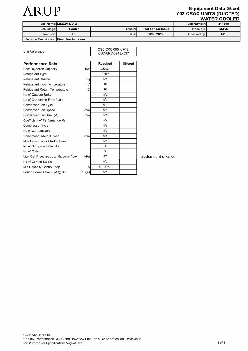
Equipment Data SheetY02 CRAC UNITS (DUCTED)
WATER COOLED
Revision Description: Final Tender Issue
Job Name: MEEZA MV-2 Job Number: 211518
Made by: KMKBFinal Tender Issue
Checked by:
Job Stage:
Revision: T0 Date:
Tender Status:
08/08/2010 APJ
Unit Reference
Performance Data
Heat Rejection Capacity kW
Refrigerant Type
Refrigerant Charge kg
Refrigerant Flow Temperature °C
Refrigerant Return Temperature °C
No of Outdoor Units
No of Condenser Fans / Unit
Condenser Fan Type
Condenser Fan Speed rpm
Condenser Fan Size (Ø) mm
Coefficient of Performance @
Compressor Type
No of Compressors
Compressor Motor Speed rpm
Max Compressor Starts/Hours
No of Refrigerant Circuits
No of Coils
Max Coil Pressure Loss @design flow kPa Includes control valve
No of Control Stages
2
n/a
1
n/a
n/a
n/a
n/a
n/a
n/a
n/a
97
16
n/a
n/a
n/a
CSC-CRC-005 to 012,
CSC-CRC-024 to 037
10
advise
CHW
n/a
OfferedRequired
Min Capacity Control Step %
Sound Power Level (Lp) @ 3m dB(A) n/a
0-100 %
AA211518-11/4-900
SP-5102-Performance CRAC and Downflow Unit Particular Specification: Revision T0
Part 2 Particular Specification: August 2010 3 of 5

Equipment Data SheetY02 CRAC UNITS (DUCTED)
WATER COOLED
Revision Description: Final Tender Issue
Job Name: MEEZA MV-2 Job Number: 211518
Made by: KMKBFinal Tender Issue
Checked by:
Job Stage:
Revision: T0 Date:
Tender Status:
08/08/2010 APJ
Noise & Vibration Data
Unit Reference
Room Unit Inlet Air
63 Hz
125 Hz
In-duct Sound Power Level 250 Hz
Lw dB 500 Hz
1 kHz
2 kHz
4 kHz
8 kHz
Room Unit Outlet Air
63 Hz
125 Hz
In-duct Sound Power Level 250 Hz
Lw dB 500 Hz
1 kHz
2 kHz
4 kHz
8 kHz
Room Unit Casing Radiated
63 Hz
83.3
CSC-CRC-005 to 012,
CSC-CRC-024 to 037
Required Offered
98.4
77.1
76.3
88.5
92.7
90.6
81.6
66.3
58.6
66.3
96.3
88.5
83.9
83.1
74.1
81.0
125 Hz
Sound Power Level 250 Hz
Lw dB 500 Hz
1 kHz
2 kHz
4 kHz
8 kHz
Anti-Vibration Mountings
Fan Anti Vibration Mount (AVM) Type
Fan AVM Static Deflection mm
Compressor AVM Type
Comp. AVM Static Deflection mm
Accessories
Microprocessor Controls ���� Water Detection ����
Common Alarm VFC Condensate Pump
Door Interlocked Mains Isolator Hot Gas ByPass
Enclosed Floorstand ���� Head Pressure Control
Open Floor Stand Supply (Bottom) Air Scoop
Integral Backflow damper ���� Return (Top) Air Hood ����
���� Filter Differential Pressure Sensor ����
see note 12
Combined 2-port Control & Pressure
Sustaining Valve (Samson/ TA/ equivalent)
OfferedRequired
88.3
79.3
90.4
64.0
56.3
74.8
74.0
n/a
n/a
Offered Required
noted
rubber
Flexible stainless steel braided connections
AA211518-11/4-900
SP-5102-Performance CRAC and Downflow Unit Particular Specification: Revision T0
Part 2 Particular Specification: August 2010 4 of 5

Equipment Data SheetY02 CRAC UNITS (DUCTED)
WATER COOLED
Revision Description: Final Tender Issue
Job Name: MEEZA MV-2 Job Number: 211518
Made by: KMKBFinal Tender Issue
Checked by:
Job Stage:
Revision: T0 Date:
Tender Status:
08/08/2010 APJ
BMS Outputs (see note 6) BMS Inputs (see note 6)
Common Alarm Volt Free Contact ���� Fan Speed Control ����
Run Status ���� Fail Status ����
Filter Change Status ����
Testing Samples
Performance Type Tests ���� Type Samples
Works Performance Tests ����
Site OEM Performance Tests ����
Works Performance Tests
Noise Performance Tests ���� Functional Performance Tests ����
Duty Performance Tests ����
Manufacturer
Manufacturer
Contact Name
Telephone Number
Fax Number
E-mail Address
Internet Address
Distributor
Contact Name
www.airdale.com
Preferred
GEA
Simon Prichard
+44 (0)7718 638549
+44 (0)1442 230647
www.gea-denco.com
Bob Stevens
+44 (0) 113 239 1000
+44 (0) 113 250 7219
Graeme Wigmore
+44 (0) 1628 403200
+44 (0) 1628 403294
Required Offered Required Offered
Required Offered Required Offered
Required Offered
Alternative
Liebert Emerson
Alternative
Airedale
www.liebert.com
Required Offered
Qatar Site and PowerGEA Middle East FZE
Scott Ross
ICAS Qatar
Contact Name
Telephone Number
Mobile Number
E-mail Address
Additional Information Comments
1 Type test data shall be provided to demonstrate that 8 All details relating to the control of and BMS interface with
the equipment performs to the required standards. this unit are detailed in the CRAC Specification.
This should be referred to in conjunction with and
2 All inputs/outputs to be wired to numbered terminals preference to this data sheet regarding control details.
within the control panel. BMS interface shall either use MODBUS or BACnet.
3 All alarm volt free contacts shall be fail safe. Contacts 9 All units shall be provided with independent unit controllers
shall be normally open, closed when healthy, open on based on readings from 1 no. Supply air temperature
alarm or loss of power sensors, 1 no. Return air temperature sensors, and 2 no.
differential pressure sensors (in addition to the filter
4 All volt free contacts to be rated at 3A inductive sensor), per unit. Controllers shall be capable of
at 230 VAC. modulating the fan air and chilled water flow rates
independently based on a combination of programmable
5 Units to be supplied with pressure independent control setpoints and BMS inputs, including 1 no. Fan speed signal.
valves (PICVs).
10 Units shall provide Run, Fail and Filter Change signals to
6 Units to be supplied with safety guard mesh protecting the BMS. Filter change alarm signal pressure shall be
fan at discharge from CRAC unit into floor void. programmable.
7 Units to be supplied with a lip around the base frame 11 Include an integral automatic transfer switch to allow power
to support adjacent floor tiles. feed from two no. diverse supplies.
12 Flexible stainless steel braided connections are to allow
for thermal expansion/contraction of +/- 18mm
+974 466 6877
Scott Ross
+971 4 8873881
+971 50 5548502
+974 436 0505
AA211518-11/4-900
SP-5102-Performance CRAC and Downflow Unit Particular Specification: Revision T0
Part 2 Particular Specification: August 2010 5 of 5

Equipment Data SheetY03_CRAC UNITS (UNDUCTED)
WATER COOLED
General Data
Unit Reference
Quantity
Location
System
Type
Performance Data
Net Total Cooling Capacity kW
Net Sensible Cooling Capacity kW
Entering Air Condition °Cdb/wb
Leaving Air Condition °Cdb/wb
Unit Air Flow Rate m³/s
External Static Pressure Pa
Unit Fan Total Pressure Pa
Number of Fans / Motors
Fan Type
Fan Drive Type
Fan Speed rpm
CHW Downflow (Frame
standing discharge to floor
void)
Direct
Advise
Advise
2/2
EC Plug
30
16
2.94
0
Required Offered
50
50
CSC-DCU-003 to 009
8 (4xRun, 4xStandby)
Data Hall Perimeter
Corridors
Critical Secondary CHW
Required Offered
CSC-CRC-001 to 004,
CSC-CRC-013 to 016,
CSC-CRC-017 to 023,
CSC-CRC-038 to 044
Data Hall Cooling Corridor
Revision Description: Final Tender Issue
Job Name: MEEZA MV-2 Job Number: 211518
Made by: KMKBFinal Tender Issue
Checked by:
Job Stage:
Revision: T0 Date:
Tender Status:
08/08/2010 APJ
CHW Single Coil Downflow
22
Critical Secondary CHW
advise
140
140
30
16
advise
50
3/3
EC Plug
Direct
adviseFan Speed rpm
Fan Size (Ø) mm
Filter Test Standard
Pre-Filter Group & Class
Pre-Filter Medium
Final-Filter Group & Class
Final-Filter Medium
Refrigerant Type
Total Refrigerant Charge kg
Coefficient of Performance @
Compressor Type
No of Compressors
Compressor Motor Speed rpm
Max Compressor Starts/Hours
No of Refrigerant Circuits
No of Control Stages
Min Capacity Control Step %
Humidifier Capacity kg/hr
Electric Heater Capacity kW
Electric Heater Stages
Room Noise Level NR 75
n/a
n/a
n/a
CHW 1 coils /
1 circuit
0-100 %
continuous
n/a
n/a
n/a
n/a
n/a
n/a
n/a
n/a
CHW
ASHRAE 52.2-
1999
MERV-6
Polyester / modacrylic
Advise
630
ASHRAE 52.2-1999
advise
n/a
MERV-6
Polyester / modacrylic
n/a (CHW)
None
630
None
CHW 2 coils / 1
circuit
n/a
n/a
n/a
n/a
n/a
n/a
n/a
0-100 %
Continuous
n/a
75
AA211518-11/4-900
SP-5102-Performance CRAC and Downflow Unit Particular Specification: Revision T0
Part 2 Particular Specification: August 2010 1 of 5

Equipment Data SheetY04_DOWNFLOW UNITS - DUCTED
WATER COOLED
General Data
Unit Reference
Model Reference
Quantity
Location
System
Type
ROOM UNIT
Performance Data
Net Total Cooling Capacity kW
Net Sensible Cooling Capacity kW
Entering Air Condition °Cdb/wb
Leaving Air Condition °Cdb/wb
Unit Air Flow Rate m³/s
External Static Pressure Pa
Unit Fan Total Pressure Pa
Number of Fans / Motors
Revision: T0 Date: 08/08/2010 Checked by: APJ
Job Name: MEEZA MV-2 Job Number: 211518
Job Stage: Tender Status: Final Tender issue Made by: KMKB
Network Termination
RoomsHV Input Rooms Transformer rooms
Critical Secondary CHW Critical Secondary CHW Critical Secondary CHW
4 (2xRun, 2xStandby) 4 (2xRun, 2xStandby)20 (10xRun,
10xStandby)
Revision Description: Final Tender Issue
CSC-DCU-065 to 066,
CSC-DCU-071 to 072CSC-DCU-067 to 070 CSC-DCU-038 to 057
Required Offered
15 25 25
CHW Downflow (Frame
standing ducted inlet
and outlet)
CHW Downflow (Frame
standing ducted inlet and
outlet)
CHW Downflow (Frame
standing ducted inlet
and outlet)
Required Offered Required Offered Required Offered
1.01 1.5 1.5
16 16 16
30 30 30
15 25 25
1/1 1/1 1/1
Advise Advise Advise
50 50 50
Number of Fans / Motors
Fan Type
Fan Drive Type
Fan Speed rpm
Fan Size (Ø) mm
Filter Test Standard
Pre-Filter Group & Class
Pre-Filter Medium
Final-Filter Group & Class
Final-Filter Medium
Refrigerant Type
Total Refrigerant Charge kg
Coefficient of Performance @
Compressor Type
No of Compressors
Compressor Motor Speed rpm
Max Compressor Starts/Hours
No of Refrigerant Circuits
No of Control Stages
Min Capacity Control Step %
Humidifier Capacity kg/hr
Electric Heater Capacity kW
Electric Heater Stages
Room Noise Level NR
EC Plug EC Plug EC Plug
1/1 1/1 1/1
ASHRAE
52.2-1999
ASHRAE
52.2-1999
ASHRAE
52.2-1999
630 630 630
Advise Advise Advise
Direct Direct Direct
n/a n/a n/a
n/a n/a n/a
Polyester / modacrylic Polyester / modacrylic Polyester / modacrylic
MERV-6 MERV-6 MERV-6
n/a n/a n/a
n/a n/a n/a
n/a n/a n/a
CHW CHW CHW
1 coils / 1
circuit
1 coils / 1
circuit
1 coils / 1
circuit
n/a n/a n/a
n/a n/a n/a
n/a n/a n/a
n/a n/a n/a
n/a n/a n/a
continuous continuous continuous
0-100 % 0-100 % 0-100 %
75 75 75
n/a n/a n/a
AA211518-11/4-900
SP-5102-Performance CRAC and Downflow Unit Particular Specification: Revision T0
Part 2 Particular Specification: August 2010 1 of 5

Equipment Data SheetY04_DOWNFLOW UNITS - DUCTED
WATER COOLED
Revision: T0 Date: 08/08/2010 Checked by: APJ
Job Name: MEEZA MV-2 Job Number: 211518
Job Stage: Tender Status: Final Tender issue Made by: KMKB
Revision Description: Final Tender Issue
Unit Reference
Construction Data
Casing Material
Casing Construction
Panel Thickness mm
Panel Insulation Material
Inner Skin Material
Inner Skin Thickness mm
Inner Skin Finish
Outer Skin Material
Outer Skin Thickness mm
Outer Skin Finish / Colour RAL
Coil Tube/Fin Material Material
Condensate Tray Material / Finish
Refrigerant Liquid Line Size DN
Refrigerant Suction Line Size DN
Humidifier Connection Type
Humidifier Connection Size
Condensate Drain Connection Type
Condensate Drain Size mm
CSC-DCU-065 to 066,
CSC-DCU-071 to 072CSC-DCU-067 to 070 CSC-DCU-038 to 057
Required Offered Required Offered Required Offered
Advise Advise Advise
Rivited Rivited Rivited
Required Offered
Zintec Zintec Zintec
natural natural natural
Zintec Zintec Zintec
Zintec Zintec Zintec
Fiber glass Fiber glass Fiber glass
Cu/Al Cu/Al Cu/Al
7021 7021 7021
0.8 0.8 0.8
Zintec Zintec Zintec
n/a n/a n/a
n/a n/a n/a
n/a n/a n/a
Aisi 304 2B Aisi 304 2B Aisi 304 2B
20 22 20
flexible flexible flexible
n/a n/a n/a
Condensate Drain Size mm
Unit Operating Weight kg
Electrical Data
Unit Max Absorbed Power kW
Unit Max Running Current A
Unit Max Starting Current A
Compressor Motor Rating kW
Fan Motor Rating kW
Electric Heater Rating kW
Humidifier Rating kW
Power Source
Electrical Supply V/Ø/Hz
Dimensional Data
Overall Width mm
Overall Depth mm
Overall Height mm
Front Clearance mm
End Clearance mm
230 400 230
20 22 20
n/a n/a n/a
5 3.6 3.6
2 3.6 3.6
0.96 1.45 1.45
n/a n/a n/a
n/a n/a n/a
1 1 x 1.45 1 x 1.45
1950 1950 1950
750 750 850
750 750 1750
400/3/50 400/3/50 400/3/50
none none none
800 800 800
AA211518-11/4-900
SP-5102-Performance CRAC and Downflow Unit Particular Specification: Revision T0
Part 2 Particular Specification: August 2010 2 of 5
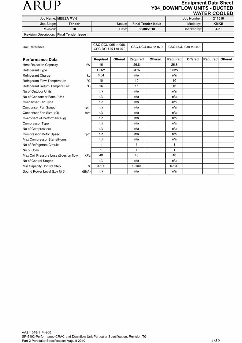
Equipment Data SheetY04_DOWNFLOW UNITS - DUCTED
WATER COOLED
Revision: T0 Date: 08/08/2010 Checked by: APJ
Job Name: MEEZA MV-2 Job Number: 211518
Job Stage: Tender Status: Final Tender issue Made by: KMKB
Revision Description: Final Tender Issue
Unit Reference
Performance Data
Heat Rejection Capacity kW
Refrigerant Type
Refrigerant Charge kg
Refrigerant Flow Temperature °C
Refrigerant Return Temperature °C
No of Outdoor Units
No of Condenser Fans / Unit
Condenser Fan Type
Condenser Fan Speed rpm
Condenser Fan Size (Ø) mm
Coefficient of Performance @
Compressor Type
No of Compressors
Compressor Motor Speed rpm
Max Compressor Starts/Hours
No of Refrigerant Circuits
No of Coils
Max Coil Pressure Loss @design flow kPa
CSC-DCU-065 to 066,
CSC-DCU-071 to 072CSC-DCU-067 to 070 CSC-DCU-038 to 057
Required Offered Required Offered Required Offered
CHW CHW CHW
0.64 n/a n/a
Required Offered
16 26.8 26.8
n/a n/a n/a
n/a n/a n/a
16 16 16
10 10 10
n/a n/a n/a
n/a n/a n/a
n/a n/a n/a
n/a n/a n/a
n/a n/a n/a
n/a n/a n/a
n/a n/a n/a
n/a n/a n/a
40 40 40
1 1 1
1 1 1
Max Coil Pressure Loss @design flow kPa
No of Control Stages
Min Capacity Control Step %
Sound Power Level (Lp) @ 3m dB(A)
40 40 40
n/a n/a n/a
n/a n/a n/a
0-100 0-100 0-100
AA211518-11/4-900
SP-5102-Performance CRAC and Downflow Unit Particular Specification: Revision T0
Part 2 Particular Specification: August 2010 3 of 5

Equipment Data SheetY04_DOWNFLOW UNITS - DUCTED
WATER COOLED
Revision: T0 Date: 08/08/2010 Checked by: APJ
Job Name: MEEZA MV-2 Job Number: 211518
Job Stage: Tender Status: Final Tender issue Made by: KMKB
Revision Description: Final Tender Issue
Noise & Vibration Data
Unit Reference
Room Unit Inlet Air
63 Hz
125 Hz
In-duct Sound Power Level 250 Hz
Lw dB 500 Hz
1 kHz
2 kHz
4 kHz
8 kHz
Room Unit Outlet Air
63 Hz
125 Hz
In-duct Sound Power Level 250 Hz
Lw dB 500 Hz
1 kHz
2 kHz
4 kHz
8 kHz
Room Unit Casing Radiated
Required Offered
CSC-DCU-065 to 066,
CSC-DCU-071 to 072CSC-DCU-067 to 070 CSC-DCU-038 to 057
Required Offered Required Offered Required Offered
64.1 68.6 68.6
67.3 76.3 76.3
66.9 72.9 72.9
60.6 65.0 65.0
48.4 57.3 57.3
52.9 60 60
57 64.7 64.7
59.8 66.8 66.8
67.1 71.6 71.6
70.3 79.3 79.3
69.9 75.9 75.9
63.6 68.0 68.0
50.4 59.3 59.3
55.9 63.0 63.0
60 67.7 67.7
62.8 69.3 69.3
Room Unit Casing Radiated
63 Hz
125 Hz
Sound Power Level 250 Hz
Lw dB 500 Hz
1 kHz
2 kHz
4 kHz
8 kHz
Anti-Vibration Mountings
Fan Anti Vibration Mount (AVM) Type
Fan AVM Static Deflection mm
Compressor AVM Type
Comp. AVM Static Deflection mm
Accessories
Microprocessor Controls ���� Water Detection ����
Common Alarm VFC Condensate Pump
Door Interlocked Mains Isolator Hot Gas ByPass
Dual Deflection Discharge Grille ���� Head Pressure Control
Stainless Steel Drip Tray ���� Filter Differential Pressure Sensor ����
���� Leak Detection ����
see note 13 Enclosed Floor stand/Ducted supply ����
Hood/Ducted return ����
61.8 66.3 66.3
65.0 74.0 74.0
64.6 70.6 70.6
58.3 62.7 62.7
46.1 55.0 55.0
50.6 57.7 57.7
54.7 62.4 62.4
57.5 64.5 64.5
to suit to suit to suit
rubber rubber rubber
n/a n/a n/a
n/a n/a n/a
Combined 2-port Control & Pressure Sustaining
Valve (Samson/ TA/ equivalent)
Required Offered Required Offered
Flexible stainless steel braided connections
AA211518-11/4-900
SP-5102-Performance CRAC and Downflow Unit Particular Specification: Revision T0
Part 2 Particular Specification: August 2010 4 of 5
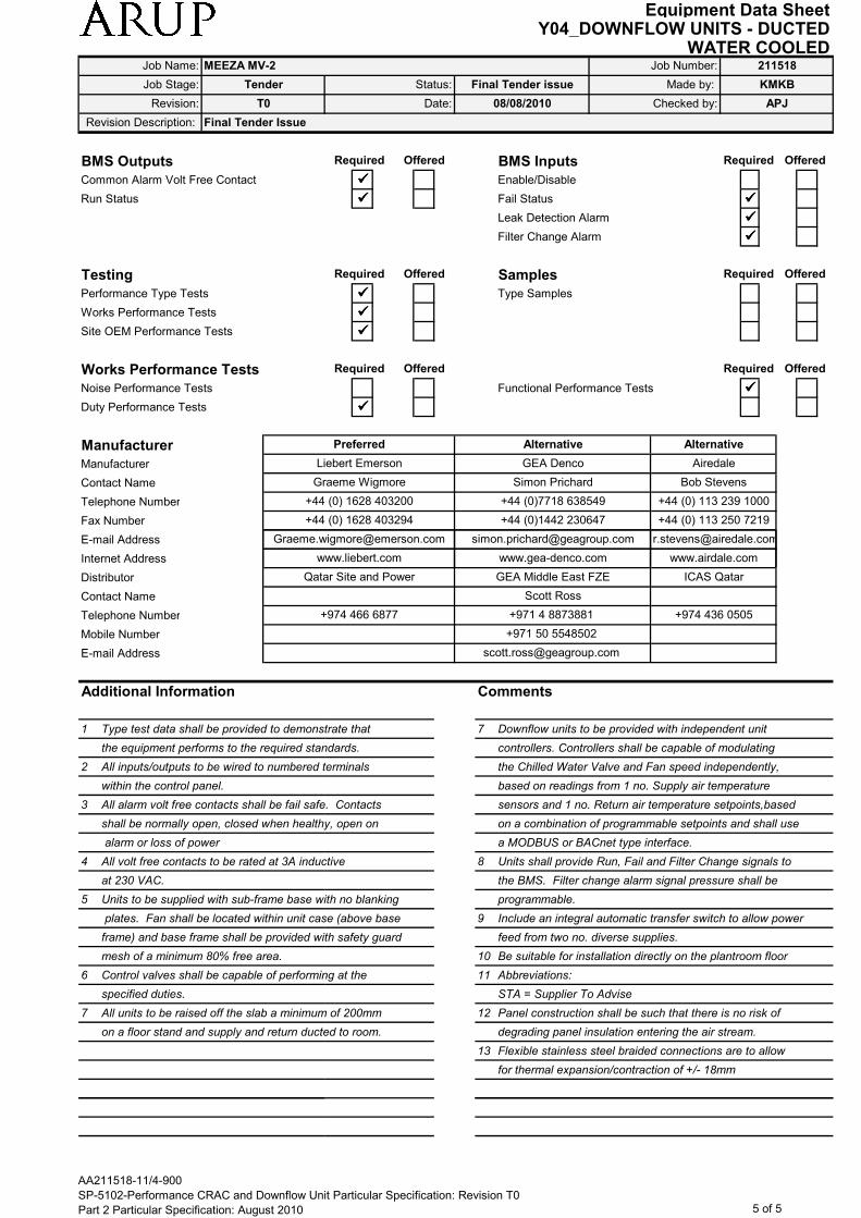
Equipment Data SheetY04_DOWNFLOW UNITS - DUCTED
WATER COOLED
Revision: T0 Date: 08/08/2010 Checked by: APJ
Job Name: MEEZA MV-2 Job Number: 211518
Job Stage: Tender Status: Final Tender issue Made by: KMKB
Revision Description: Final Tender Issue
BMS Outputs BMS Inputs
Common Alarm Volt Free Contact ���� Enable/Disable
Run Status ���� Fail Status ����
Leak Detection Alarm ����
Filter Change Alarm ����
Testing Samples
Performance Type Tests ���� Type Samples
Works Performance Tests ����
Site OEM Performance Tests ����
Works Performance Tests
Noise Performance Tests Functional Performance Tests ����
Duty Performance Tests ����
Manufacturer
Manufacturer
Contact Name
Telephone Number
Fax Number
E-mail Address
Graeme Wigmore Simon Prichard Bob Stevens
+44 (0) 1628 403200 +44 (0)7718 638549 +44 (0) 113 239 1000
Offered
Required Offered Required Offered
Required Offered Required Offered
Preferred
Required Offered Required
www.liebert.com www.gea-denco.com www.airdale.com
Alternative Alternative
Liebert Emerson GEA Denco Airedale
+44 (0) 1628 403294 +44 (0)1442 230647 +44 (0) 113 250 7219
[email protected] [email protected] [email protected]
Internet Address
Distributor
Contact Name
Telephone Number
Mobile Number
E-mail Address
Additional Information Comments
1 Type test data shall be provided to demonstrate that 7 Downflow units to be provided with independent unit
the equipment performs to the required standards. controllers. Controllers shall be capable of modulating
2 All inputs/outputs to be wired to numbered terminals the Chilled Water Valve and Fan speed independently,
within the control panel. based on readings from 1 no. Supply air temperature
3 All alarm volt free contacts shall be fail safe. Contacts sensors and 1 no. Return air temperature setpoints,based
shall be normally open, closed when healthy, open on on a combination of programmable setpoints and shall use
alarm or loss of power a MODBUS or BACnet type interface.
4 All volt free contacts to be rated at 3A inductive 8 Units shall provide Run, Fail and Filter Change signals to
at 230 VAC. the BMS. Filter change alarm signal pressure shall be
5 Units to be supplied with sub-frame base with no blanking programmable.
plates. Fan shall be located within unit case (above base 9 Include an integral automatic transfer switch to allow power
frame) and base frame shall be provided with safety guard feed from two no. diverse supplies.
mesh of a minimum 80% free area. 10 Be suitable for installation directly on the plantroom floor
6 Control valves shall be capable of performing at the 11 Abbreviations:
specified duties. STA = Supplier To Advise
7 All units to be raised off the slab a minimum of 200mm 12 Panel construction shall be such that there is no risk of
on a floor stand and supply and return ducted to room. degrading panel insulation entering the air stream.
13 Flexible stainless steel braided connections are to allow
for thermal expansion/contraction of +/- 18mm
+971 50 5548502
Scott Ross
+974 466 6877 +971 4 8873881 +974 436 0505
www.liebert.com www.gea-denco.com www.airdale.com
Qatar Site and Power GEA Middle East FZE ICAS Qatar
AA211518-11/4-900
SP-5102-Performance CRAC and Downflow Unit Particular Specification: Revision T0
Part 2 Particular Specification: August 2010 5 of 5

Equipment Data SheetY05_DOWNFLOW UNITS - UNDUCTED (Part 1 of 2)
WATER COOLED
General Data
Unit Reference
Model Reference
Quantity
Location
System
Type
ROOM UNIT
Performance Data
Net Total Cooling Capacity kW
Net Sensible Cooling Capacity kW
Entering Air Condition °Cdb/wb
Leaving Air Condition °Cdb/wb
Unit Air Flow Rate m³/s
External Static Pressure Pa
Unit Fan Total Pressure Pa
Number of Fans / Motors
Fan Type
Job Name: MEEZA MV-2 Job Number: 211518
Required
CHW Downflow (Floor
standing, discharge at
low level)
2 (1xRun, 1xStandby)
Offered Offered
CSC-DCU-001 to 002
Central Corridor
Required Offered Required
CSC-DCU-010 to 013 CSC-DCU-018 to 037
25
0
Made by: KMKBFinal Tender Issue
Checked by: APJ08/08/2010
25
Job Stage:
Revision: T0 Date:
Tender Status:
25
30
Critical Secondary CHW Critical Secondary CHW Critical Secondary CHW
16 16
0
Revision Description: Final Tender Issue
4 (2xRun, 2xStandby)20 (10xRun,
10xStandby)
Required Offered
1.5 1.5
0
4.2
Mechanical and Fire
PlantroomsLV Switchrooms
80
CHW Downflow (Floor
standing, discharge at
low level)
CHW Downflow (Frame
standing discharge to
floor void)
80
16
25
30 30
EC Plug EC Plug EC Plug
Advise Advise
1/1 1/1
Advise
2/2
Fan Type
Fan Drive Type
Fan Speed rpm
Fan Size (Ø) mm
Filter Test Standard
Pre-Filter Group & Class
Pre-Filter Medium
Final-Filter Group & Class
Final-Filter Medium
Refrigerant Type
Total Refrigerant Charge kg
Coefficient of Performance @
Compressor Type
No of Compressors
Compressor Motor Speed rpm
Max Compressor Starts/Hours
No of Refrigerant Circuits
No of Control Stages
Min Capacity Control Step %
Humidifier Capacity kg/hr
Electric Heater Capacity kW
Electric Heater Stages
Room Noise Level NR
Direct Direct Direct
EC Plug EC Plug EC Plug
MERV-6 MERV-6 MERV-6
ASHRAE
52.2-1999
ASHRAE
52.2-1999
ASHRAE
52.2-1999
Advise Advise
630 630
Advise
630
CHW CHW CHW
n/a n/a n/a
Polyester / modacrylic Polyester / modacrylic
n/a n/a
Polyester / modacrylic
n/a
n/a n/a n/a
n/a n/a n/a
n/a n/a
n/a n/a
n/a
n/a
0-100 % 0-100 % 0-100 %
1 coils / 1
circuit
1 coils / 1
circuit
1 coils / 1
circuit
n/a n/a
n/a n/a
n/a
n/a
n/a
continuous continuous
n/a n/a
continuous
n/a
75 75
n/a n/a
75
n/a
n/a n/a
AA211518-11/4-900
SP-5102-Performance CRAC and Downflow Unit Particular Specification: Revision T0
Part 2 Particular Specification: August 2010 1 of 5

Equipment Data SheetY05_DOWNFLOW UNITS - UNDUCTED (Part 1 of 2)
WATER COOLEDJob Name: MEEZA MV-2 Job Number: 211518
Made by: KMKBFinal Tender Issue
Checked by: APJ08/08/2010
Job Stage:
Revision: T0 Date:
Tender Status:
Revision Description: Final Tender Issue
Unit Reference
Construction Data
Casing Material
Casing Construction
Panel Thickness mm
Panel Insulation Material
Inner Skin Material
Inner Skin Thickness mm
Inner Skin Finish
Outer Skin Material
Outer Skin Thickness mm
Outer Skin Finish / Colour RAL
Coil Tube/Fin Material Material
Condensate Tray Material / Finish
Refrigerant Liquid Line Size DN
Refrigerant Suction Line Size DN
Humidifier Connection Type
Humidifier Connection Size
Condensate Drain Connection Type
Condensate Drain Size mm
CSC-DCU-010 to 013 CSC-DCU-018 to 037
Required Offered
CSC-DCU-001 to 002
Required Offered
Advise Advise Advise
Rivited Rivited Rivited
Required Offered
Zintec Zintec Zintec
natural natural natural
Zintec Zintec Zintec
Fiber glass Fiber glass
Zintec Zintec
Fiber glass
Zintec
Cu/Al Cu/Al Cu/Al
7021 7021 7021
Zintec Zintec
0.8 0.8
Zintec
0.8
n/a n/a n/a
n/a n/a n/a
Aisi 304 2B Aisi 304 2B
n/a n/a
Aisi 304 2B
n/a
230 230 600
20 20 20
n/a n/a
flexible flexible
n/a
flexible
Unit Operating Weight kg
Electrical Data
Unit Max Absorbed Power kW
Unit Max Running Current A
Unit Max Starting Current A
Compressor Motor Rating kW
Fan Motor Rating kW
Electric Heater Rating kW
Humidifier Rating kW
Power Source
Electrical Supply V/Ø/Hz
Dimensional Data
Overall Width mm
Overall Depth mm
Overall Height mm
Front Clearance mm
End Clearance mm
230 230 600
n/a n/a n/a
7.23.6 3.6
1.45 1.45
3.6 3.6
3.98
7.2
n/a
400/3/50
n/a n/a
1 x 1.45 1 x 1.45
n/an/a n/a
2 x 1.99
750 750 850
750 750 1750
400/3/50 400/3/50
800
none
800
1950 1950 1950
800
none none
AA211518-11/4-900
SP-5102-Performance CRAC and Downflow Unit Particular Specification: Revision T0
Part 2 Particular Specification: August 2010 2 of 5

Equipment Data SheetY05_DOWNFLOW UNITS - UNDUCTED (Part 1 of 2)
WATER COOLEDJob Name: MEEZA MV-2 Job Number: 211518
Made by: KMKBFinal Tender Issue
Checked by: APJ08/08/2010
Job Stage:
Revision: T0 Date:
Tender Status:
Revision Description: Final Tender Issue
Unit Reference
Performance Data
Heat Rejection Capacity kW
Refrigerant Type
Refrigerant Charge kg
Refrigerant Flow Temperature °C
Refrigerant Return Temperature °C
No of Outdoor Units
No of Condenser Fans / Unit
Condenser Fan Type
Condenser Fan Speed rpm
Condenser Fan Size (Ø) mm
Coefficient of Performance @
Compressor Type
No of Compressors
Compressor Motor Speed rpm
Max Compressor Starts/Hours
No of Refrigerant Circuits
No of Coils
Max Coil Pressure Loss @design flowkPa
CHW
1
40
n/a
40
1
n/a n/a
1 1
n/a
40
n/a
n/a n/a
n/a
n/a n/a
1
n/a n/a
n/a
n/a n/a
n/a
1
n/a
n/a
10
n/a
n/a
n/a
n/a
n/a
n/a
n/a n/a
n/a
n/a
n/a
CSC-DCU-010 to 013 CSC-DCU-018 to 037 CSC-DCU-001 to 002
n/a n/a
16 16
n/a
Required Offered Required Offered
26.8 26.8
CHW
10
n/a
CHW
n/a
84.3
10
16
n/a
n/a
Required Offered
No of Control Stages
Min Capacity Control Step %
Sound Power Level (Lp) @ 3m dB(A) n/a n/a
0-100
n/a
n/a n/a n/a
0-100 0-100
AA211518-11/4-900
SP-5102-Performance CRAC and Downflow Unit Particular Specification: Revision T0
Part 2 Particular Specification: August 2010 3 of 5

Equipment Data SheetY05_DOWNFLOW UNITS - UNDUCTED (Part 1 of 2)
WATER COOLEDJob Name: MEEZA MV-2 Job Number: 211518
Made by: KMKBFinal Tender Issue
Checked by: APJ08/08/2010
Job Stage:
Revision: T0 Date:
Tender Status:
Revision Description: Final Tender Issue
Noise & Vibration Data
Unit Reference
Room Unit Inlet Air
63 Hz
125 Hz
In-duct Sound Power Level 250 Hz
Lw dB 500 Hz
1 kHz
2 kHz
4 kHz
8 kHz
Room Unit Outlet Air
63 Hz
125 Hz
In-duct Sound Power Level 250 Hz
Lw dB 500 Hz
1 kHz
2 kHz
4 kHz
8 kHz
Room Unit Casing Radiated
72.9 72.9 77.6
65.0 65.0 69.7
CSC-DCU-010 to 013 CSC-DCU-018 to 037 CSC-DCU-001 to 002
Required Offered Required Offered Required Offered
64.7 64.7 69.4
66.8 66.8 71.5
76.3 76.3
68.6 68.6
81.0
73.3
75.9 75.9 84.7
68.0 68.0 76.8
60 60
57.3 57.3
64.7
62.0
67.7 67.7 78.6
69.3 69.3 78.4
79.3 79.3
71.6 71.6
88.1
80.4
62.7 62.7 67.4
63.0 63.0
59.3 59.3
76.5
71.8
63 Hz
125 Hz
Sound Power Level 250 Hz
Lw dB 500 Hz
1 kHz
2 kHz
4 kHz
8 kHz
Anti-Vibration Mountings
Fan Anti Vibration Mount (AVM) Type
Fan AVM Static Deflection mm
Compressor AVM Type
Comp. AVM Static Deflection mm
Accessories
Microprocessor Controls ���� Water Detection ����
Common Alarm VFC Condensate Pump
Door Interlocked Mains Isolator Hot Gas ByPass
Dual Deflection Discharge Grille ���� see note 15 Head Pressure Control
Stainless Steel Drip Tray ���� Filter Differential Pressure Sensor ����
Open Floor Stand ���� see note 14 Leak Detection ����
���� see note 13Flexible stainless steel braided
connections
Required Offered Required Offered
70.6 70.6 75.3
62.7 62.7 67.4
62.4 62.4 67.1
64.5 64.5 69.2
74.0 74.0
66.3 66.3
78.7
71.0
57.7 57.7
55.0 55.0
62.4
59.7
n/a n/a
rubber rubber
to suit to suit to suit
rubber
Combined 2-port Control & Pressure
Sustaining Valve (Samson/ TA/ equivalent)
n/a n/a n/a
n/a
AA211518-11/4-900
SP-5102-Performance CRAC and Downflow Unit Particular Specification: Revision T0
Part 2 Particular Specification: August 2010 4 of 5

Equipment Data SheetY05_DOWNFLOW UNITS - UNDUCTED (Part 1 of 2)
WATER COOLEDJob Name: MEEZA MV-2 Job Number: 211518
Made by: KMKBFinal Tender Issue
Checked by: APJ08/08/2010
Job Stage:
Revision: T0 Date:
Tender Status:
Revision Description: Final Tender Issue
BMS Outputs BMS Inputs
Common Alarm Volt Free Contact ���� Enable/Disable
Run Status ���� Fail Status ����
Leak Detection Alarm ����
Filter Change Alarm ����
Testing Samples
Performance Type Tests ���� Type Samples
Works Performance Tests ����
Site OEM Performance Tests ����
Works Performance Tests
Noise Performance Tests Functional Performance Tests ����
Duty Performance Tests ����
Manufacturer
Manufacturer
Contact Name
Telephone Number
Fax Number
E-mail Address
Required Offered
Required Offered
www.airdale.com
+44 (0) 113 250 7219
[email protected] [email protected] [email protected]
+44 (0) 1628 403294 +44 (0)1442 230647
www.liebert.com www.gea-denco.com
Bob Stevens
Offered
Required Offered
+44 (0) 1628 403200 +44 (0)7718 638549 +44 (0) 113 239 1000
Graeme Wigmore Simon Prichard
Alternative
Liebert Emerson GEA Denco Airedale
Preferred Alternative
Required
Required Offered Required Offered
Internet Address
Distributor
Contact Name
Telephone Number
Mobile Number
E-mail Address
Additional Information Comments
1 Type test data shall be provided to demonstrate that 8 Units shall provide Run, Fail and Filter Change signals to
the equipment performs to the required standards. the BMS. Filter change alarm signal pressure shall be
2 All inputs/outputs to be wired to numbered terminals programmable.
within the control panel. 9 Include an integral automatic transfer switch to allow power
3 All alarm volt free contacts shall be fail safe. Contacts feed from two no. diverse supplies.
shall be normally open, closed when healthy, open on 10 Be suitable for installation directly on the plantroom floor
alarm or loss of power 11 Abbreviations:
4 All volt free contacts to be rated at 3A inductive STA = Supplier To Advise
at 230 VAC. 12 Panel construction shall be such that there is no risk of
5 Units to be supplied with sub-frame base with no blanking degrading panel insulation entering the air stream.
plates. Fan shall be located within unit case (above base 13 Flexible stainless steel braided connections are to allow
frame) and base frame shall be provided with safety guard for thermal expansion/contraction of +/- 18mm
mesh of a minimum 80% free area. 14 Floor stands required on all units. Open floor stands specifically
6 Control valves shall be capable of required on frame standing discharge to floor void units.
performing at the specified duties. 15 Dual deflection grilles required on frame standing discharge
7 Downflow units to be provided with independent unit at low level units.
controllers. Controllers shall be capable of modulating
the Chilled Water Valve and Fan speed independently,
based on readings from 1 no. Supply air temperature
sensors and 1 no. Return air temperature setpoints,based
on a combination of programmable setpoints and shall use
ICAS Qatar
Scott Ross
Qatar Site and Power GEA Middle East FZE
+974 466 6877 +971 4 8873881 +974 436 0505
+971 50 5548502
www.airdale.comwww.liebert.com www.gea-denco.com
on a combination of programmable setpoints and shall use
a MODBUS or BACnet type interface.
AA211518-11/4-900
SP-5102-Performance CRAC and Downflow Unit Particular Specification: Revision T0
Part 2 Particular Specification: August 2010 5 of 5

Equipment Data SheetY05 DOWNFLOW UNITS - UNDUCTED (Part 2 of 2)
WATER COOLED
General Data
Unit Reference
Model Reference
Quantity
Location
System
Type
ROOM UNIT
Performance Data
Net Total Cooling Capacity kW
Net Sensible Cooling Capacity kW
Entering Air Condition °Cdb/wb
Leaving Air Condition °Cdb/wb
Unit Air Flow Rate m³/s
External Static Pressure Pa
Unit Fan Total Pressure Pa
Number of Fans / Motors
Tender
Secondary Non Critical
CHW
Secondary Non Critical
CHW
16
9.96
54.25
16
Job Name: MEEZA MV-2 Job Number: 211518
1 1
Offered
NSC-DCU-002 NSC-DCU-003
BMS Control
Required Offered Required
Secondary Non Critical
CHW
Bunker
NSC-DCU-001
Job Stage:
Revision: T0
9.48
CHW Downflow (Floor
standing, discharge at
low level)
CHW Downflow (Floor
standing, discharge at
low level)
9.42
20
16
Made by:
20
186 183
2/2
SCFinal Tender Issue
Checked by: APJ08/08/2010
9.93
26
Date:
Status:
26 26
54.37
Revision Description: Final Tender Issue
1
Required Offered
20
3.95 0.90 0.96
Burn-in Room
2/2
428
2/2
CHW Downflow (Floor
standing, discharge at
low level)
Fan Type
Fan Drive Type
Fan Speed rpm
Fan Size (Ø) mm
Filter Test Standard
Pre-Filter Group & Class
Pre-Filter Medium
Final-Filter Group & Class
Final-Filter Medium
Refrigerant Type
Total Refrigerant Charge kg
Coefficient of Performance @
Compressor Type
No of Compressors
Compressor Motor Speed rpm
Max Compressor Starts/Hours
No of Refrigerant Circuits
No of Control Stages
Min Capacity Control Step %
Humidifier Capacity kg/hr
Electric Heater Capacity kW
Electric Heater Stages
Room Noise Level NR
Direct Direct Direct
ASHRAE
52.2-1999
MERV-6 MERV-6 MERV-6
EC Plug EC Plug EC Plug
ASHRAE
52.2-1999
ASHRAE
52.2-1999
1268
560 560
776 776
560
CHW CHW CHW
n/a n/a n/a
Polyester /
modacrylic
n/a n/a
Polyester /
modacrylic
Polyester /
modacrylic
n/a
n/a n/a n/a
n/a n/a n/a
n/a
n/a n/a
n/a n/a
n/a
1 coils / 1
circuit
1 coils / 1
circuit
1 coils / 1
circuit
n/a
n/a n/a
n/a n/a
n/a
continuous
n/a n/a
continuous continuous
n/a
0-100 % 0-100 % 0-100 %
4575 35
n/a
n/a
n/a n/a
n/a n/a
AA211518-11/4-900
SP-5102-Performance CRAC and Downflow Unit Particular Specification: Revision T0
Part 2 Particular Specification: August 2010 1 of 5

Equipment Data SheetY05 DOWNFLOW UNITS - UNDUCTED (Part 2 of 2)
WATER COOLED
Tender
Job Name: MEEZA MV-2 Job Number: 211518
Job Stage:
Revision: T0
Made by: SCFinal Tender Issue
Checked by: APJ08/08/2010Date:
Status:
Revision Description: Final Tender Issue
Unit Reference
Construction Data
Casing Material
Casing Construction
Panel Thickness mm
Panel Insulation Material
Inner Skin Material
Inner Skin Thickness mm
Inner Skin Finish
Outer Skin Material
Outer Skin Thickness mm
Outer Skin Finish / Colour RAL
Coil Tube/Fin Material Material
Condensate Tray Material / Finish
Refrigerant Liquid Line Size DN
Refrigerant Suction Line Size DN
Humidifier Connection Type
Humidifier Connection Size
Condensate Drain Connection Type
Condensate Drain Size mm
NSC-DCU-001
Required OfferedRequired Offered
NSC-DCU-002 NSC-DCU-003
Lateral
Panels
Lateral
Panels
Lateral
Panels
Rivited Rivited Rivited
Required Offered
ZintecZintec Zintec
Zintec Zintec Zintec
1 1 1
Fiber glass
Zintec Zintec
Fiber glass Fiber glass
Zintec
CU/AL CU/AL CU/AL
7021 7021 7021
Zintec
0,8 0,8
Zintec Zintec
0,8
n/a n/a n/a
n/a n/a n/a
AISI 304 2B
n/a n/a
AISI 304 2B AISI 304 2B
n/a
650 200 200
20 20 20
n/a
flexible flexible
n/a n/a
flexible
Unit Operating Weight kg
Electrical Data
Unit Max Absorbed Power kW
Unit Max Running Current A
Unit Max Starting Current A
Compressor Motor Rating kW
Fan Motor Rating kW
Electric Heater Rating kW
Humidifier Rating kW
Power Source
Electrical Supply V/Ø/Hz
Dimensional Data
Overall Width mm
Overall Depth mm
Overall Height mm
Front Clearance mm
End Clearance mm
650 200 200
n/an/a n/a
0.1 0.10.2
Current
Power7.2 3.6
Current
Power
Current
Power3.6
n/a
n/a
n/a n/a
2 x 1.54
n/an/a
0.380.37
850 750 750
1750 750750
400/3/50400/3/50 400/3/50
800
none
800
1980 19801980
none
800
none
AA211518-11/4-900
SP-5102-Performance CRAC and Downflow Unit Particular Specification: Revision T0
Part 2 Particular Specification: August 2010 2 of 5

Equipment Data SheetY05 DOWNFLOW UNITS - UNDUCTED (Part 2 of 2)
WATER COOLED
Tender
Job Name: MEEZA MV-2 Job Number: 211518
Job Stage:
Revision: T0
Made by: SCFinal Tender Issue
Checked by: APJ08/08/2010Date:
Status:
Revision Description: Final Tender Issue
Unit Reference
Performance Data
Heat Rejection Capacity kW
Refrigerant Type
Refrigerant Charge kg
Refrigerant Flow Temperature °C
Refrigerant Return Temperature °C
No of Outdoor Units
No of Condenser Fans / Unit
Condenser Fan Type
Condenser Fan Speed rpm
Condenser Fan Size (Ø) mm
Coefficient of Performance @
Compressor Type
No of Compressors
Compressor Motor Speed rpm
Max Compressor Starts/Hours
No of Refrigerant Circuits
No of Coils
Max Coil Pressure Loss @design flow kPa
n/a
CHW
34
1
31
n/a
n/a
n/an/a n/a
n/a
n/a
1
n/a
n/a
1 1
n/an/a
1
33
n/a
n/an/a
n/an/a
n/a
n/a
n/a
1
n/a
n/a
n/a
n/a
n/a
n/a
NSC-DCU-001 NSC-DCU-002 NSC-DCU-003
11
n/a
17
n/a n/a
Required Offered Required Offered
57.60
CHW
11
n/a
Required Offered
10.49.9
11
n/a
17 17
n/a
n/a
n/a
n/a
CHW
n/a
No of Control Stages
Min Capacity Control Step %
Sound Power Level (Lp) @ 3m dB(A) n/a n/an/a
n/a n/an/a
0-100 0-100 0-100
AA211518-11/4-900
SP-5102-Performance CRAC and Downflow Unit Particular Specification: Revision T0
Part 2 Particular Specification: August 2010 3 of 5

Equipment Data SheetY05 DOWNFLOW UNITS - UNDUCTED (Part 2 of 2)
WATER COOLED
Tender
Job Name: MEEZA MV-2 Job Number: 211518
Job Stage:
Revision: T0
Made by: SCFinal Tender Issue
Checked by: APJ08/08/2010Date:
Status:
Revision Description: Final Tender Issue
Noise & Vibration Data
Unit Reference
Room Unit Inlet Air
63 Hz
125 Hz
In-duct Sound Power Level 250 Hz
Lw dB 500 Hz
1 kHz
2 kHz
4 kHz
8 kHz
Room Unit Outlet Air
63 Hz
125 Hz
In-duct Sound Power Level 250 Hz
Lw dB 500 Hz
1 kHz
2 kHz
4 kHz
8 kHz
Room Unit Casing Radiated
76.1 58 57.9
68.2 51.7 51.6
Required Offered
NSC-DCU-001 NSC-DCU-002 NSC-DCU-003
Required Offered Required Offered
67.9 42 42
70 45 45
79.5
71.8 49
54 54
49
83.2 61 60.9
75.3 54.7 54.6
63.2
60.5 38
40 40
38
73 42 42
75 45 45
82
78 49
54 54
49
65.9 49.5 49.3
70.3
66.6 38
40 40
38
63 Hz
125 Hz
Sound Power Level 250 Hz
Lw dB 500 Hz
1 kHz
2 kHz
4 kHz
8 kHz
Anti-Vibration Mountings
Fan Anti Vibration Mount (AVM) Type
Fan AVM Static Deflection mm
Compressor AVM Type
Comp. AVM Static Deflection mm
Accessories
Microprocessor Controls ���� Water Detection ����
Common Alarm VFC Condensate Pump
Door Interlocked Mains Isolator Hot Gas ByPass
Dual Deflection Discharge Grille ���� Head Pressure Control
Stainless Steel Drip Tray ���� Filter Differential Pressure Sensor ����
Leak Detection ����
���� see note 13Combined 2-port Control & Pressure
Sustaining Valve (Samson/ TA/ equivalent)
Required Offered Required Offered
73.8 55.7 55.6
65.9 49.5 49.3
60.9
58.2 38
40 40
38
69.5 49
54 54
49
n/a
n/a n/a
n/a n/a
rubberrubber rubber
to suit to suit to suit
Flexible stainless steel braided
connections
n/a
65.5 42 42
67.7 45 45
77.2
AA211518-11/4-900
SP-5102-Performance CRAC and Downflow Unit Particular Specification: Revision T0
Part 2 Particular Specification: August 2010 4 of 5
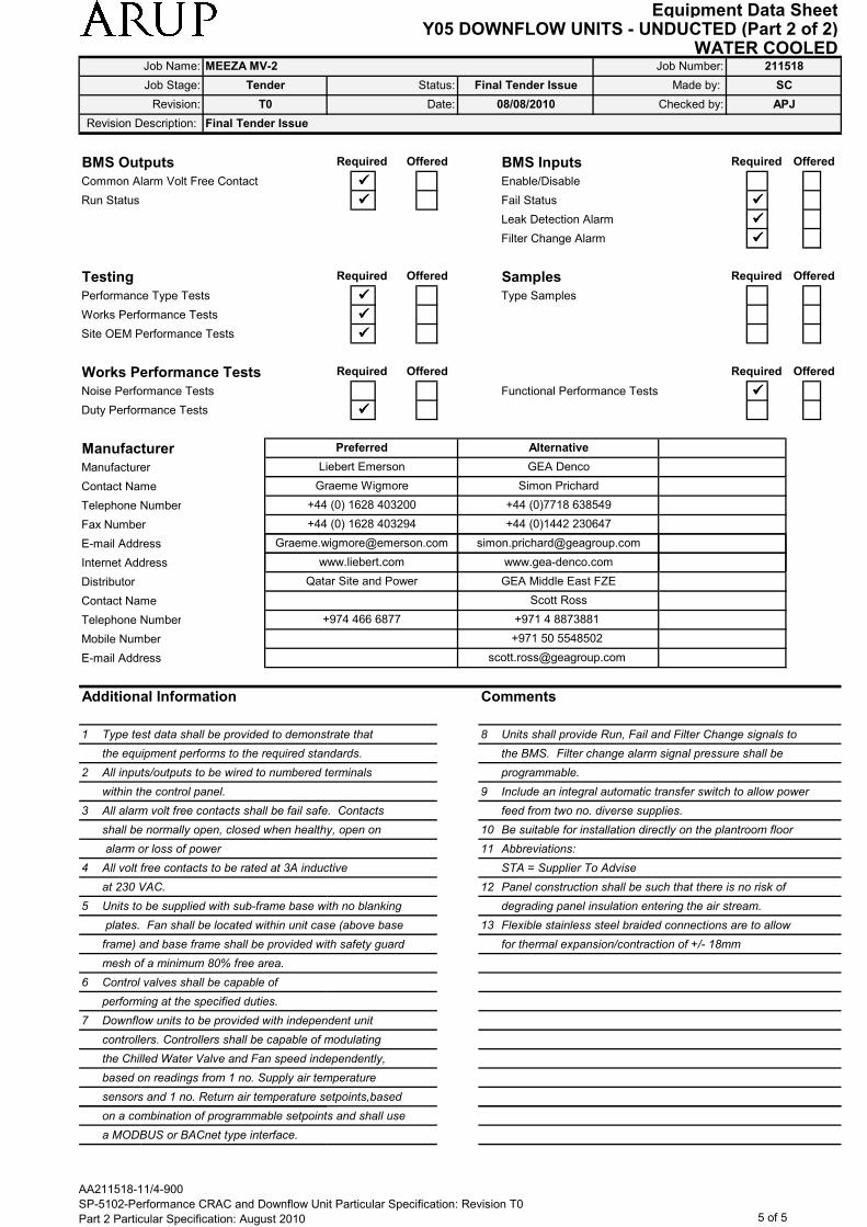
Equipment Data SheetY05 DOWNFLOW UNITS - UNDUCTED (Part 2 of 2)
WATER COOLED
Tender
Job Name: MEEZA MV-2 Job Number: 211518
Job Stage:
Revision: T0
Made by: SCFinal Tender Issue
Checked by: APJ08/08/2010Date:
Status:
Revision Description: Final Tender Issue
BMS Outputs BMS Inputs
Common Alarm Volt Free Contact ���� Enable/Disable
Run Status ���� Fail Status ����
Leak Detection Alarm ����
Filter Change Alarm ����
Testing Samples
Performance Type Tests ���� Type Samples
Works Performance Tests ����
Site OEM Performance Tests ����
Works Performance Tests
Noise Performance Tests Functional Performance Tests ����
Duty Performance Tests ����
Manufacturer
Manufacturer
Contact Name
Telephone Number
Fax Number
E-mail Address
www.gea-denco.com
[email protected] [email protected]
Required Offered
Required Offered
www.liebert.com
+44 (0) 1628 403294 +44 (0)1442 230647
Offered
Required Offered
Offered
+44 (0) 1628 403200 +44 (0)7718 638549
Graeme Wigmore Simon Prichard
Liebert Emerson GEA Denco
Preferred Alternative
Required
Required Offered Required
Internet Address
Distributor
Contact Name
Telephone Number
Mobile Number
E-mail Address
Additional Information Comments
1 Type test data shall be provided to demonstrate that 8 Units shall provide Run, Fail and Filter Change signals to
the equipment performs to the required standards. the BMS. Filter change alarm signal pressure shall be
2 All inputs/outputs to be wired to numbered terminals programmable.
within the control panel. 9 Include an integral automatic transfer switch to allow power
3 All alarm volt free contacts shall be fail safe. Contacts feed from two no. diverse supplies.
shall be normally open, closed when healthy, open on 10 Be suitable for installation directly on the plantroom floor
alarm or loss of power 11 Abbreviations:
4 All volt free contacts to be rated at 3A inductive STA = Supplier To Advise
at 230 VAC. 12 Panel construction shall be such that there is no risk of
5 Units to be supplied with sub-frame base with no blanking degrading panel insulation entering the air stream.
plates. Fan shall be located within unit case (above base 13 Flexible stainless steel braided connections are to allow
frame) and base frame shall be provided with safety guard for thermal expansion/contraction of +/- 18mm
mesh of a minimum 80% free area.
6 Control valves shall be capable of
performing at the specified duties.
7 Downflow units to be provided with independent unit
controllers. Controllers shall be capable of modulating
the Chilled Water Valve and Fan speed independently,
based on readings from 1 no. Supply air temperature
sensors and 1 no. Return air temperature setpoints,based
on a combination of programmable setpoints and shall use
www.gea-denco.com
Scott Ross
Qatar Site and Power GEA Middle East FZE
+974 466 6877 +971 4 8873881
+971 50 5548502
www.liebert.com
on a combination of programmable setpoints and shall use
a MODBUS or BACnet type interface.
AA211518-11/4-900
SP-5102-Performance CRAC and Downflow Unit Particular Specification: Revision T0
Part 2 Particular Specification: August 2010 5 of 5

Equipment Data SheetY03_CRAC UNITS (UNDUCTED)
WATER COOLED
Revision Description: Final Tender Issue
Job Name: MEEZA MV-2 Job Number: 211518
Made by: KMKBFinal Tender Issue
Checked by:
Job Stage:
Revision: T0 Date:
Tender Status:
08/08/2010 APJ
Unit Reference
Construction Data
Casing Material
Casing Construction
Panel Thickness mm
Panel Insulation Material
Inner Skin Material
Inner Skin Thickness mm
Inner Skin Finish
Outer Skin Material
Outer Skin Thickness mm
Outer Skin Finish / Colour RAL
Coil Tube/Fin Material Material
Condensate Tray Material / Finish
Refrigerant Liquid Line Size DN
Refrigerant Suction Line Size DN
Humidifier Connection Type
Humidifier Connection Size
Condensate Drain Connection Type
Condensate Drain Size (internal dia.) mm 20
flexible
n/a
n/a
n/a
Cu/Al
Aisi 304 2B
n/a
Zintec
0.8
7021
Zintec
Zintec
natural
Rivited
Advise
Fiber glass
Required Offered
Zintec
CSC-DCU-003 to 009
Zintec
CSC-CRC-001 to 004,
CSC-CRC-013 to 016,
CSC-CRC-017 to 023,
CSC-CRC-038 to 044
Required Offered
Zintec
Fiber glass
advise
Rivited
Cu/Al
Zintec
natural
Zintec
0.8
7021
flexible
Aisi 304 2B
n/a
n/a
20
n/a
n/a
Condensate Drain Size (internal dia.) mm
Unit Operating Weight kg
Electrical Data
Unit Max Absorbed Power kW
Unit Max Running Current A
Unit Max Starting Current A
Compressor Motor Rating kW
Fan Motor Rating kW
Electric Heater Rating kW
Humidifier Rating kW
Power Source
Electrical Supply V/Ø/Hz
Dimensional Data
Overall Width mm
Overall Depth mm
Overall Height mm
Front Clearance mm
End Clearance mm
800
none
850
1950
20
n/a
400/3/50
1750
n/a
2 x 0.73
n/a
1.46
7.2
7.2
480
n/a
20
840
15
9.33
15
3 x 3.11
n/a
n/a
400/3/50
3350
2300
800
985
none
AA211518-11/4-900
SP-5102-Performance CRAC and Downflow Unit Particular Specification: Revision T0
Part 2 Particular Specification: August 2010 2 of 5
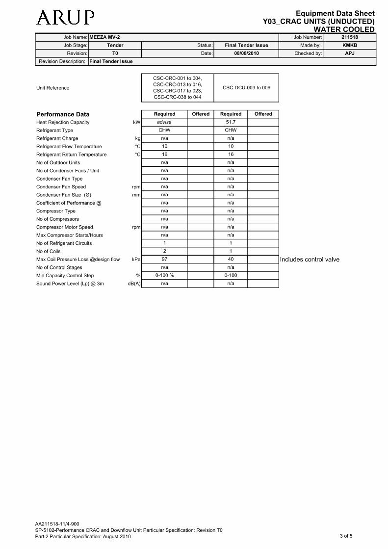
Equipment Data SheetY03_CRAC UNITS (UNDUCTED)
WATER COOLED
Revision Description: Final Tender Issue
Job Name: MEEZA MV-2 Job Number: 211518
Made by: KMKBFinal Tender Issue
Checked by:
Job Stage:
Revision: T0 Date:
Tender Status:
08/08/2010 APJ
Unit Reference
Performance Data
Heat Rejection Capacity kW
Refrigerant Type
Refrigerant Charge kg
Refrigerant Flow Temperature °C
Refrigerant Return Temperature °C
No of Outdoor Units
No of Condenser Fans / Unit
Condenser Fan Type
Condenser Fan Speed rpm
Condenser Fan Size (Ø) mm
Coefficient of Performance @
Compressor Type
No of Compressors
Compressor Motor Speed rpm
Max Compressor Starts/Hours
No of Refrigerant Circuits
No of Coils
Max Coil Pressure Loss @design flow kPa Includes control valve
1
40
n/a
n/a
1
n/a
n/a
n/a
n/a
n/a
n/a
16
n/a
n/a
51.7
CHW
n/a
10
CSC-DCU-003 to 009
Required Offered
2
1
n/a
n/a
n/a
n/a
n/a
n/a
n/a
97
16
n/a
n/a
n/a
CSC-CRC-001 to 004,
CSC-CRC-013 to 016,
CSC-CRC-017 to 023,
CSC-CRC-038 to 044
10
advise
CHW
n/a
OfferedRequired
Max Coil Pressure Loss @design flow kPa Includes control valve
No of Control Stages
Min Capacity Control Step %
Sound Power Level (Lp) @ 3m dB(A)
40
n/a
0-100
n/a
n/a n/a
0-100 %
97
AA211518-11/4-900
SP-5102-Performance CRAC and Downflow Unit Particular Specification: Revision T0
Part 2 Particular Specification: August 2010 3 of 5

Equipment Data SheetY03_CRAC UNITS (UNDUCTED)
WATER COOLED
Revision Description: Final Tender Issue
Job Name: MEEZA MV-2 Job Number: 211518
Made by: KMKBFinal Tender Issue
Checked by:
Job Stage:
Revision: T0 Date:
Tender Status:
08/08/2010 APJ
Noise & Vibration Data
Unit Reference
Room Unit Inlet Air
63 Hz
125 Hz
In-duct Sound Power Level 250 Hz
Lw dB 500 Hz
1 kHz
2 kHz
4 kHz
8 kHz
Room Unit Outlet Air
63 Hz
125 Hz
In-duct Sound Power Level 250 Hz
Lw dB 500 Hz
1 kHz
2 kHz
4 kHz
8 kHz
Room Unit Casing Radiated
94.7
61
73.3
71.5
69.4
69.7
77.6
81
62.2
57.5
54.8
73.8
66.1
64.3
Required Offered
CSC-DCU-003 to 009
62.5
70.4
83.3
CSC-CRC-001 to 004,
CSC-CRC-013 to 016,
CSC-CRC-017 to 023,
CSC-CRC-038 to 044
Required Offered
98.4
77.1
76.3
88.5
92.7
90.6
81.6
66.3
58.6
66.3
96.3
88.5
83.9
83.1
74.1
Room Unit Casing Radiated
63 Hz
125 Hz
Sound Power Level 250 Hz
Lw dB 500 Hz
1 kHz
2 kHz
4 kHz
8 kHz
Anti-Vibration Mountings
Fan Anti Vibration Mount (AVM) Type
Fan AVM Static Deflection mm
Compressor AVM Type
Comp. AVM Static Deflection mm
Accessories
Microprocessor Controls ���� Water Detection ����
Common Alarm VFC Condensate Pump
Door Interlocked Mains Isolator Hot Gas ByPass
Enclosed Floorstand Head Pressure Control
Open Floor Stand ���� Supply (Bottom) Air Scoop
Integral Backflow damper ���� Return (Top) Air Hood
���� Filter Differential Pressure Sensor ����
see note 12
n/a
n/a
55.2
52.5
rubber
68.1
71.5
63.8
60.2
Combined 2-port Control & Pressure
Sustaining Valve (Samson/ TA/ equivalent)
OfferedRequired
88.3
79.3
81.0
90.4
64.0
56.3
74.8
74.0
62
59.9
n/a
to suit
n/a
Offered Required
noted
rubber
Flexible stainless steel braided connections
AA211518-11/4-900
SP-5102-Performance CRAC and Downflow Unit Particular Specification: Revision T0
Part 2 Particular Specification: August 2010 4 of 5

Equipment Data SheetY03_CRAC UNITS (UNDUCTED)
WATER COOLED
Revision Description: Final Tender Issue
Job Name: MEEZA MV-2 Job Number: 211518
Made by: KMKBFinal Tender Issue
Checked by:
Job Stage:
Revision: T0 Date:
Tender Status:
08/08/2010 APJ
BMS Outputs (see note 6) BMS Inputs (see note 6)
Common Alarm Volt Free Contact ���� Fan Speed Control ����
Run Status ���� Fail Status ����
Filter Change Status ����
Testing Samples
Performance Type Tests ���� Type Samples
Works Performance Tests ����
Site OEM Performance Tests ����
Works Performance Tests
Noise Performance Tests ���� Functional Performance Tests ����
Duty Performance Tests ����
Manufacturer
Manufacturer
Contact Name
Telephone Number
Fax Number
E-mail Address
Internet Address
Distributor
Contact Name
www.airdale.com
Preferred
GEA
Simon Prichard
+44 (0)7718 638549
+44 (0)1442 230647
www.gea-denco.com
Bob Stevens
+44 (0) 113 239 1000
+44 (0) 113 250 7219
Graeme Wigmore
+44 (0) 1628 403200
+44 (0) 1628 403294
Required Offered Required Offered
Required Offered Required Offered
Required Offered
Alternative
Liebert Emerson
Alternative
Airedale
www.liebert.com
Required Offered
Qatar Site and PowerGEA Middle East FZE
Scott Ross
ICAS Qatar
Contact Name
Telephone Number
Mobile Number
E-mail Address
Additional Information Comments
1 Type test data shall be provided to demonstrate that 8 All details relating to the control of and BMS interface with
the equipment performs to the required standards. this unit are detailed in the CRAC Specification.
This should be referred to in conjunction with and
2 All inputs/outputs to be wired to numbered terminals preference to this data sheet regarding control details.
within the control panel. BMS interface shall either use MODBUS or BACnet.
3 All alarm volt free contacts shall be fail safe. Contacts 9 All units shall be provided with independent unit controllers
shall be normally open, closed when healthy, open on based on readings from 1 no. Supply air temperature
alarm or loss of power sensors, 1 no. Return air temperature sensors, and 2 no.
differential pressure sensors (in addition to the filter
4 All volt free contacts to be rated at 3A inductive sensor), per unit. Controllers shall be capable of
at 230 VAC. modulating the fan air and chilled water flow rates
independently based on a combination of programmable
5 Units to be supplied with pressure independent control setpoints and BMS inputs, including 1 no. Fan speed signal.
valves (PICVs).
10 Units shall provide Run, Fail and Filter Change signals to
6 Units to be supplied with safety guard mesh protecting the BMS. Filter change alarm signal pressure shall be
fan at discharge from CRAC unit into floor void. programmable.
7 Units to be supplied with a lip around the base frame 11 Include an integral automatic transfer switch to allow power
to support adjacent floor tiles. feed from two no. diverse supplies.
12 Flexible stainless steel braided connections are to allow
for thermal expansion/contraction of +/- 18mm
+974 466 6877
Scott Ross
+971 4 8873881
+971 50 5548502
+974 436 0505
AA211518-11/4-900
SP-5102-Performance CRAC and Downflow Unit Particular Specification: Revision T0
Part 2 Particular Specification: August 2010 5 of 5


