
� One location message of 11 seconds, and
three alarm messages of three seconds each.
� Recorded messages stored in non-volatile
memory.
� All telephone numbers stored in non-volatile
memory.
� Unique, easy to use, ‘Follow Me’ telephone
number.
� Three trigger inputs, programmable as active
high or low, linked to phone numbers or alarm
messages.
� Last event memory.
� Comprehensive test facilities.
� Supplied with telephone lead for easy
installation.
Features
Description
Speech Dialler
Engineering Information
The Informa is a Speech Dialler for use with intruder
alarm systems. When the control panel recognises an
alarm it triggers the Informa.
The Informa uses a telephone line to dial a pre-
programmed telephone number. It then replays a
previously recorded message, thereby alerting the
recipient of the call to the alarm and potential
intrusion.

Table of Contents
Features . . . . . . . . . . . . . . . . . . . . . . . . . . . . . . .1
Description . . . . . . . . . . . . . . . . . . . . . . . . . . . . .1
Messages . . . . . . . . . . . . . . . . . . . . . . . . . . . . . . .2
Telephone Numbers . . . . . . . . . . . . . . . . . . . . . . .3
The Follow Me Function . . . . . . . . . . . . . . . . . . . 3
Operating Setup . . . . . . . . . . . . . . . . . . . . . . . . . .3
Input Association . . . . . . . . . . . . . . . . . . . . . . . . . 3
Sequential Dialling . . . . . . . . . . . . . . . . . . . . . .3
Non-Sequential Dialling . . . . . . . . . . . . . . . . .4
Message Acknowledgement . . . . . . . . . . . . . . . .4
Mounting . . . . . . . . . . . . . . . . . . . . . . . . . . . . . . .5
Connecting the Power Supply . . . . . . . . . . . . . .6
Connecting to Control Panels . . . . . . . . . . . . . . .6
Communicating Panels . . . . . . . . . . . . . . . . . . . . .6
Connecting to the Accenta Gen 4 . . . . . . . . . . 6
Connecting for the Follow Me Function . . . . . . . .6
Connecting to ‘Bells Only’ panels . . . . . . . . . . . . .6
Connecting to the Telephone Network . . . . . . . . .7
Using the Supplied Telephone Lead . . . . . . . .7
Connecting Directly to a Master Jack . . . . . . . . . .7
Parallel Connection . . . . . . . . . . . . . . . . . . . . . . . .8
PABX Connection . . . . . . . . . . . . . . . . . . . . . . . . .8
Payphones . . . . . . . . . . . . . . . . . . . . . . . . . . . . . . .8
Engineer Programming . . . . . . . . . . . . . . . . . . . 9
Displaying the Informa Status [0] . . . . . . . . . . . 9
The Informa Tones . . . . . . . . . . . . . . . . . . . . . . .9
Volume Control [1] . . . . . . . . . . . . . . . . . . . . . . .9
Message Timeout [2] . . . . . . . . . . . . . . . . . . . . .10
Setting up the Inputs [3] . . . . . . . . . . . . . . . . . .10
Setting Trigger Levels [4] . . . . . . . . . . . . . . . . .10
Viewing the Last Event [5] . . . . . . . . . . . . . . . .10
Enabling the Follow Me Function [6] . . . . . . . .11
Changing the Customer Code [8] . . . . . . . . . . .11
Changing the Engineer Code [9] . . . . . . . . . . . .11
Recording Messages [REC] . . . . . . . . . . . . . . .11
Playback of Messages [PLAY] . . . . . . . . . . . . .12
Performing a Test Call [TEST] . . . . . . . . . . . .12
Programming Telephone Numbers [TEL] . . . . .12
Quitting Engineer Mode [QUIT] . . . . . . . . . . .12
NVM Reset . . . . . . . . . . . . . . . . . . . . . . . . . . . .13
Factory settings (defaults) . . . . . . . . . . . . . . . . .13
Applications . . . . . . . . . . . . . . . . . . . . . . . . . . .13
Ringer Equivalence Number . . . . . . . . . . . . . . . 13
Informa – Speech Dialler
2
Technical Specifications . . . . . . . . . . . . . . . . . .14
Using the Informa as a Standalone Unit . . . . . .14
Quick Reference . . . . . . . . . . . . . . . . . . . . . . . .17
Engineering Information
3
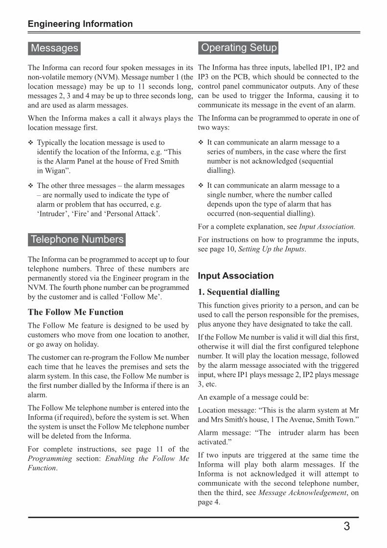
The Informa can record four spoken messages in its
non-volatile memory (NVM). Message number 1 (the
location message) may be up to 11 seconds long,
messages 2, 3 and 4 may be up to three seconds long,
and are used as alarm messages.
When the Informa makes a call it always plays the
location message first.
� Typically the location message is used to
identify the location of the Informa, e.g. “This
is the Alarm Panel at the house of Fred Smith
in Wigan”.
� The other three messages – the alarm messages
– are normally used to indicate the type of
alarm or problem that has occurred, e.g.
‘Intruder’, ‘Fire’ and ‘Personal Attack’.
Messages
Telephone Numbers
The Informa can be programmed to accept up to four
telephone numbers. Three of these numbers are
permanently stored via the Engineer program in the
NVM. The fourth phone number can be programmed
by the customer and is called ‘Follow Me’.
The Follow Me Function
The Follow Me feature is designed to be used by
customers who move from one location to another,
or go away on holiday.
The customer can re-program the Follow Me number
each time that he leaves the premises and sets the
alarm system. In this case, the Follow Me number is
the first number dialled by the Informa if there is an
alarm.
The Follow Me telephone number is entered into the
Informa (if required), before the system is set. When
the system is unset the Follow Me telephone number
will be deleted from the Informa.
For complete instructions, see page 11 of the
Programming section: Enabling the Follow MeFunction.
The Informa has three inputs, labelled IP1, IP2 and
IP3 on the PCB, which should be connected to the
control panel communicator outputs. Any of these
can be used to trigger the Informa, causing it to
communicate its message in the event of an alarm.
The Informa can be programmed to operate in one of
two ways:
� It can communicate an alarm message to a
series of numbers, in the case where the first
number is not acknowledged (sequential
dialling).
� It can communicate an alarm message to a
single number, where the number called
depends upon the type of alarm that has
occurred (non-sequential dialling).
For a complete explanation, see Input Association.
For instructions on how to programme the inputs,
see page 10, Setting Up the Inputs.
Input Association
1. Sequential dialling
This function gives priority to a person, and can be
used to call the person responsible for the premises,
plus anyone they have designated to take the call.
If the Follow Me number is valid it will dial this first,
otherwise it will dial the first configured telephone
number. It will play the location message, followed
by the alarm message associated with the triggered
input, where IP1 plays message 2, IP2 plays message
3, etc.
An example of a message could be:
Location message: “This is the alarm system at Mr
and Mrs Smith's house, 1 The Avenue, Smith Town.”
Alarm message: “The intruder alarm has been
activated.”
If two inputs are triggered at the same time the
Informa will play both alarm messages. If the
Informa is not acknowledged it will attempt to
communicate with the second telephone number,
then the third, see Message Acknowledgement, on
page 4.
Operating Setup

Informa – Speech Dialler
4
Message Acknowledgement
The recipient must always acknowledge the call
made by the Informa in order to terminate its dialling
sequence.
After replaying its two or more messages the
Informa will produce a single tone for one second.
The recipient then has an interval of five seconds to
press the * (star) key on the telephone.
The Informa will repeat its tone for one second and
the user must again press the * key within five
seconds.
The Informa will then sound two short beeps to
indicate that it has received the acknowledgement
and then hang up. Note that it is only possible to
acknowledge the call with a tone-dialling telephone.
2. Non-sequential dialling
This function is based on the type of alarm.
If IP1 has been triggered, the Informa will dial the
first telephone number and play the location
message, followed by message 2.
If IP2 has been triggered, the Informa will dial the
second telephone number and play the location
message, followed by message 3.
If IP3 has been triggered, the Informa will dial the
third telephone number and play the location
message, followed by message 4.
If there is no acknowledgement, the Informa will
only attempt seven more times to communicate with
the original telephone number.

Engineering Information
5
Mounting
InstallationBefore installing the Informa, power down the
control panel to which it is to be connected, by
removing both mains and battery power.
Break out the cable clamp strap from the back plate.
Fasten the Informa’s backplate securely to the
required position on a wall, using fixing points A, B
and C, and breaking out whichever cable entry is to
be used.
NB: Ensure that wall fixing point C is fixed securely,
as this ensures tamper activation if the unit is forcibly
removed from the wall.
The cutouts are designed to take mini-trunking
directly. Run the cable from the alarm panel to the
Informa back plate as required.
Run the cable from the position of the telephone
master socket to the Informa back plate. Secure both
of these cables to the nearest cable clamp using the
cable clamp strap removed earlier. Use the two small
self-tapping screws to fasten the clamp strap across
the two cables.
Wall fixing points
Cover fixing screwbreakoutCable clamp
4-Cable entry cutoutsfor mini trunking
A
BC
0V TAMP12V
INH
IP3
IP2
IP1
A BTAMP
NVM link
NVM
LK1

Informa – Speech Dialler
6
The Informa must be connected to a +12V power
supply which is fused at 2 Amps or less. Standard
alarm cable – 7/0.2mm multicore or equivalent –
should be used.
Connect the alarm cable wiring – starting with the
+12V and 0V connections from the alarm panel –
and wire them into the +12V and 0V terminals of the
Informa.
If the control panel is not being used as the power
supply for Informa, then a common 0V connection
connection between the control panel and Informa
must be made.
Now wire as many trigger channels from the alarm
panel to the speech dialler as required.
Connecting the Power Supply
Connecting to Control Panels
Connecting to Communicating Panels
Most communicating control panels use a +ve
(positive) to trigger the communicator outputs. If the
control panel used has a –ve communicator output,
Informa inputs must be programmed as Active High
(+ve trigger), see page 10, Setting Trigger Levels.
The Accenta Gen 4 has a dedicated communicator
or programmable communicator outputs. This will
allow a location message followed by one of three
alarm messages to be sent by the Informa.
Connecting for the Follow Me Function
The INH input is used with the ‘Follow Me’ function,
and should be connected to the SET output from the
control panel.
When the Follow Me function is enabled, the INH
input does not inhibit alarms from IP1 but cancels
the Follow Me number whenever the panel is unset.
Connecting to the Accenta Gen 4
Three-channel (three-message) operation is possible
with an Accenta Gen 4. Connect the Informa to the
panel.
Program all Informa inputs as Active Low (this is
the default).
To enable the use of the Follow Me function,
connect the SET+ of the panel to the INH input on
the Informa. This connection is unnecessary if
Follow Me is not used.
SET
INT IP1IP2IP3INH
Control Panel Informa
FIREPA
Connecting to a Communicating Control Panel
Connecting to ‘Bells Only’ Panels
Optima Compact Gen 4 control panels are ‘bells
only’ panels. With this type of panel, the Informa
may be used as a single-channel dialler triggered
from the bell output.
Connect trigger IP1 to the bell output of the panel.
The Informa will only be triggered by the bell when
the panel has been set.
Most control panels use a –ve (negative) to trigger
the bell or sounder. If the control panel used has a
–ve bell trigger, the Informa's inputs must be
programmed as active low (– trigger). See page 10,
Setting Trigger Levels. The factory default for these
inputs is Active Low.
Connect the Informa as shown below:
a) SET +: With a SET + connection, a Personal
Alarm (PA) will not trigger the Informa unless
the panel is set (armed).
b) Program the Informa’s inputs IP1, IP2 and IP3
as Active Low (the default).
The INH input will only
inhibit alarms from IP1.i
Tamper connections are provided for connection to
the host control panel, if required

Engineering Information
7
Connecting to a Bells Only Control Panel
Note that with a bells only panel,
PA only triggers the Informa when
the panel is set (armed).iConnecting to the Telephone Network
Honeywell Security recommends that the Informa
be connected to an ex-directory standard PSTN
telephone line, and that ideally no other telephone
apparatus is connected to the same line.
The Informa may be connected to the telephone
network by either of the two methods below:
a) Using the supplied RJ-11 telecoms lead and
suitable adapter to plug into a standard
telephone socket.
b) Using a direct connection to a BT master jack
socket using a special telephone cable, see page
7, Connecting Directly to a Master Jack.
Using the Supplied Telephone Lead
This two-way lead must be wired to the terminals
on the Informa PCB as follows:
Wire Colour PCB Terminal
White A
Red B
Connecting Directly to a Master Jack
Direct connection to a master jack socket should be
undertaken by an approved installer, using the
connections described below.
The cable used to connect the Informa to the master
socket must conform to BT specification CW1308.
This has a single-strand conductor of 0.5mm2. On
no account should any other type of cable be used.
At the master socket identify the terminals A and B.
This can be done either by reference to the terminal
numbers on the socket, or by the wiring code.
Connect one end of the telephone cable to the
Informa terminals labelled A and B. Strip back 5mm
of insulation from each of the two conductors, insert
the conductors into the terminal block and tighten the
screw. The telephone cable should be routed away
from all other cables inside the housing.
Connect the other end of the telephone cable to the
master socket. It may be necessary to use a special
IDT termination tool to do this securely.
Terminal Number Wire Colour
A 5 White with blue rings
B 2 Blue with white rings
SET
BELL B- IP1IP2IP3INH
Control Panel Informa
c) Program the INH input as Active High.
Note that if the Follow Me function is enabled in
a Bells Only panel, a bell test will cause the
dialler to start the call procedure, because the
SET+ or SET connection to INH does not prevent
dialling when the panel is unset.
Refer to page 3, The Follow Me Function.

Engineering Information
8
Parallel Connection
Although not recommended by Honeywell, the
Informa may be connected to the same telephone
line as other telephone apparatus.
The Informa can only be connected in parallel with
other apparatus, since a series connection facility is
not provided.
When connected in this way the installer should
check that the combined REN (Ringer Equivalence
Number) of all equipment connected in parallel does
not exceed the maximum REN permitted by your
telephone provider.
PABX Connection
When used on a PABX system the Informa may need
access to an ‘outside line’ before attempting to dial a
telephone number. In this case all telephone numbers
programmed into the host control panel should be
prefixed with the ‘outside line’ code of the PABX.
This is usually 9.
Consult your PABX provider for further details, if
required.
Payphones
The Informa is not suitable for connection as an
extension to a payphone or 1 + 1 carrier system.

Informa – Speech Dialler
Programming
1 2 3 40
6 7 8 95
TELQUIT TEST PLAY REC
ON1
34
2
Engineer Programming
Displaying the Informa Status [0]
The Informa is on standby when only the green
Power ‘ON’ LED is lit.
To enter the engineer menu:
a) Key in the four-digit engineer code.
The factory set engineer code is 9999.
The first three red LEDs light.
Refer also to the Quick Reference on page 17 of
this guide.
You can display the programmed state of each input
to the Informa.
a) Press [0].
The state of the inputs is displayed on the LEDs.
LEDs 1 to 3 show the state of inputs IP1to IP3,
LED 4 shows the state of the inhibit input
(INH).
An LED is lit when the associated input is active.
Note that the inputs can be programmed to be
Active High or Low.
b) Press QUIT to finish.
Volume Control [1]
You can alter the volume of the messages when they
are played back.
By default the Informa uses Medium 1.
a) Press 1 to enter volume control mode.
b) Press:
[1] to select Minimum volume
[2] to select Medium 1 volume
[3] to select Medium 2 volume
[4] to select Maximum volume.
When you have chosen the setting, the Informa
automatically resets to the top level of the
Engineering menu.
9
The Informa Tones
� To confirm an action, the Informa sounds a fast
double-beep.
� To alert you to an error, the Informa sounds a long
two-note signal.
Engineering Information
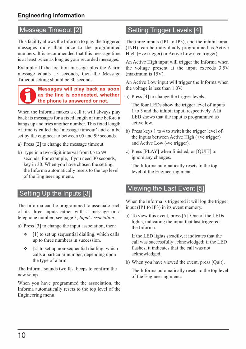
This facility allows the Informa to play the triggered
messages more than once to the programmed
numbers. It is recommended that this message time
is at least twice as long as your recorded messages.
Example: If the location message plus the Alarm
message equals 15 seconds, then the Message
Timeout setting should be 30 seconds.
When the Informa makes a call it will always play
back its messages for a fixed length of time before it
hangs up and tries another number. This fixed length
of time is called the ‘message timeout’ and can be
set by the engineer to between 05 and 99 seconds.
a) Press [2] to change the message timeout.
b) Type in a two-digit interval from 05 to 99
seconds. For example, if you need 30 seconds,
key in 30. When you have chosen the setting,
the Informa automatically resets to the top level
of the Engineering menu.
Messages will play back as soon
as the line is connected, whether
the phone is answered or not.i
Message Timeout [2]
Setting Up the Inputs [3]
Setting Trigger Levels [4]
The Informa can be programmed to associate each
of its three inputs either with a message or a
telephone number; see page 3, Input Association.
a) Press [3] to change the input association, then:
� [1] to set up sequential dialling, which calls
up to three numbers in succession.
� [2] to set up non-sequential dialling, which
calls a particular number, depending upon
the type of alarm.
The Informa sounds two fast beeps to confirm the
new setup.
When you have programmed the association, the
Informa automatically resets to the top level of the
Engineering menu.
The three inputs (IP1 to IP3), and the inhibit input
(INH), can be individually programmed as Active
High (+ve trigger) or Active Low (-ve trigger).
An Active High input will trigger the Informa when
the voltage present at the input exceeds 3.5V
(maximum is 15V).
An Active Low input will trigger the Informa when
the voltage is less than 1.0V.
a) Press [4] to change the trigger levels.
The four LEDs show the trigger level of inputs
1 to 3 and the inhibit input, respectively. A lit
LED shows that the input is programmed as
active low.
b) Press keys 1 to 4 to switch the trigger level of
the inputs between Active High (+ve trigger)
and Active Low (-ve trigger).
c) Press [PLAY] when finished, or [QUIT] to
ignore any changes.
The Informa automatically resets to the top
level of the Engineering menu.
Viewing the Last Event [5]
When the Informa is triggered it will log the trigger
input (IP1 to IP3) in its event memory.
a) To view this event, press [5]. One of the LEDs
lights, indicating the input that last triggered
the Informa.
If the LED lights steadily, it indicates that the
call was successfully acknowledged; if the LED
flashes, it indicates that the call was not
acknowledged.
b) When you have viewed the event, press [Quit].
The Informa automatically resets to the top level
of the Engineering menu.
10

Informa – Speech Dialler
Enabling the Follow Me Function [6]
Changing the Customer Code [8]
Recording Messages [REC]
The Follow Me function permits the customer to
enter a telephone number each time the alarm system
is set. The Informa always uses the Follow Me
number (if programmed) in preference to the first
telephone number.
a) Press [6] to enable or disable the Follow Me
function.
b) Press [0] to disable the Follow Me function once
it is enabled (LED 4 lit) or Press [1] to re-enable
the function (LED 1 lit).
The Follow Me function is cancelled each time the
panel is Unset.
Access to the customer menu, for the programming
of messages and telephone numbers, is protected by
a four-digit code. By default, this is 0123.
This can be changed either by the customer or the
engineer, as follows:
� Press [8], followed by the new four-digit code.
The Informa sounds a fast double-beep to
confirm that the new code has been recorded.
If the code is the same as the engineer code, the
Informa will not accept it and sounds a long
two-note error tone.
After the code is changed, the Informa
automatically resets to the top level of the
Engineering menu.
Changing the Engineer Code [9]
The engineer code is 9999 by default. You can
change this as follows:
� Press [9] followed by the new four-digit code.
The Informa sounds a short double-beep to
confirm that the new code has been recorded.
After the code is changed, the Informa
automatically resets to the top level of the
Engineering menu.
You can program up to four messages.
� Message 1 is used as the location message.
� Messages 2, 3 and 4 are used as alarm
messages.
To record or re-record a message:
a) Press [REC] (there is a 1-second pause).
b) Press the number of the message (1 to 4, where
1 corresponds to the location message).
The Informa pauses for one second then sounds
a tone for one second.
b) Now speak clearly into the microphone, which
is positioned just below the LEDs. Message 1
may be up to 11 seconds long; the three alarm
messages are 3 seconds long.
Example
� A location message can be: Message 1- "This is
the alarm system at Mr & Mrs Smith's house, 1
The Avenue, Smith Town. There is"
� The alarm message can be:
− Message 2: "Fire alarm"
− Message 3: "Personal Attack"
− Message 4: "Intruder alarm"
The Informa automatically stops recording at the end
of the message delay. If the announcement to be
recorded in message 1 is much shorter than 11
seconds you can stop the recording at any time by
pressing [PLAY].
After the message is recorded there is a short
interval, after which the Informa plays back your
recorded message.
11
Engineering Information
Playback of Messages [PLAY]
Performing a Test Call [TEST]
Programming Telephone Nos [TEL]
Quitting Engineer Mode [QUIT]
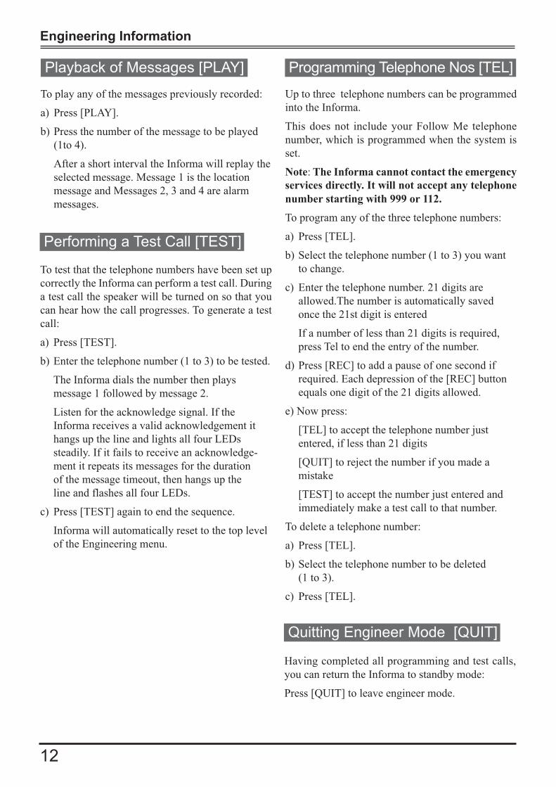
To play any of the messages previously recorded:
a) Press [PLAY].
b) Press the number of the message to be played
(1to 4).
After a short interval the Informa will replay the
selected message. Message 1 is the location
message and Messages 2, 3 and 4 are alarm
messages.
To test that the telephone numbers have been set up
correctly the Informa can perform a test call. During
a test call the speaker will be turned on so that you
can hear how the call progresses. To generate a test
call:
a) Press [TEST].
b) Enter the telephone number (1 to 3) to be tested.
The Informa dials the number then plays
message 1 followed by message 2.
Listen for the acknowledge signal. If the
Informa receives a valid acknowledgement it
hangs up the line and lights all four LEDs
steadily. If it fails to receive an acknowledge-
ment it repeats its messages for the duration
of the message timeout, then hangs up the
line and flashes all four LEDs.
c) Press [TEST] again to end the sequence.
Informa will automatically reset to the top level
of the Engineering menu.
Up to three telephone numbers can be programmed
into the Informa.
This does not include your Follow Me telephone
number, which is programmed when the system is
set.
Note: The Informa cannot contact the emergency
services directly. It will not accept any telephone
number starting with 999 or 112.
To program any of the three telephone numbers:
a) Press [TEL].
b) Select the telephone number (1 to 3) you want
to change.
c) Enter the telephone number. 21 digits are
allowed.The number is automatically saved
once the 21st digit is entered
If a number of less than 21 digits is required,
press Tel to end the entry of the number.
d) Press [REC] to add a pause of one second if
required. Each depression of the [REC] button
equals one digit of the 21 digits allowed.
e) Now press:
[TEL] to accept the telephone number just
entered, if less than 21 digits
[QUIT] to reject the number if you made a
mistake
[TEST] to accept the number just entered and
immediately make a test call to that number.
To delete a telephone number:
a) Press [TEL].
b) Select the telephone number to be deleted
(1 to 3).
c) Press [TEL].
Having completed all programming and test calls,
you can return the Informa to standby mode:
Press [QUIT] to leave engineer mode.
12

Informa – Speech Dialler
NVM Reset
The engineer code, and all other programmable
parameters, can be reset to their factory defaults by
following the sequence below:
a) Power down the Informa by removing the 12V
supply to the Informa.
b) Slacken the front cover screw and remove the
front assembly to expose the PCB.
c) Short together the 2 pins labelled “NVM” LK 1
(see diagram on page 5) with the blade of a
screwdriver, or the supplied shorting link, and at
the same time power up the Informa. The NVM
will be reset.
d) Now remove the short from the 2 pins and refit
the front cover.
Your Informa will return to the factory setting.
The Informa is suitable for connection to the
following types of telephone line:
a) Direct exchange lines (PSTN) supporting
DTMF (tone) only.
b) PABX exchanges, with or without secondary
proceed indication.
The Informa can be used for the following:
� Automatic call initialisation
� Operation in the absence of a proceed
indication.
� Automatic calling: Multiple repeat attempts.
Applications
The above sequence will not clear
the messages that have previously
been recorded.i
Engineer Code 9999
Customer Code 0123
Volume Control Medium 1
Message Timeout 45 seconds
Input Association Messages (1)
Trigger Levels All inputs active low
Follow Me function Disabled
Telephone numbers All blank
Factory Settings (defaults)
13
Ringer Equivalence Number
The REN of the Informa is 1. The sum of the REN
values of all telephone apparatus connected to a
single line should not exceed 4.
Where the REN is not specified, it is assumed to
be 1.

Engineering Information
Technical Specifications
Power supply Provided by the host control panel
Power supply voltage 10 to 18V (max)
Power supply current 50mA quiescent, 200mA (max) when operating
Negative Input Trigger voltage < 1.0V
Positive input Trigger voltage 3.5V to 15V (max)
Temperature range (operating) 0 to 60ºC
Dialling method DTMF (tone)
Ringer Equivalence Number REN = 1
14
The Informa may be used as a standalone unit, i.e.
NOT connected to an Intruder Alarm Panel. In this
case, an external supply and switches can be used to
operate the Inputs IP1, IP2 and IP3 to trigger the
Informa. The Inputs can be configured for Active
Low or Active High operation.
a) The diagram below is for an Active Low input
configured using a relay to trigger IP1.
0V TAMP12V
INH
IP3
IP2
IP1
Informa
+ve-ve
PSU
Relay
0V TAMP12V
INH
IP3
IP2
IP1
Informa
+ve-ve
PSU
Relay
If the Inhibit (INH) is not being used, it should
be left as Active Lowi
b) The diagram that follows is for an Active High
input configured using a relay to trigger IP1. In this
case the wiring is reversed, and the inputs are
connected to -ve.
Using the Informa as a Standalone Unit

Informa – Speech Dialler
Index
A
Accenta Gen 4 . . . . . . . . . . . . . . . . . . . . . . . . . . .6
Acknowledgement . . . . . . . . . . . . . . . . . . .3, 4, 12
Alarm message . . . . . . . . . . . . . . . . . .1, 3, 10, 11
Association, input . . . . . . . . . . . . . . . . . . . . . .3, 10, 13
B
‘Bells Only’ . . . . . . . . . . . . . . . . . . . . . . . . . . . . .6
C
Cable clamp strap . . . . . . . . . . . . . . . . . . . . . . . .5
Call, performing a test . . . . . . . . . . . . . . . . . . . .12
Connecting
for the ‘Follow Me’ function . . . . . . . . . . . . .6
to control panels . . . . . . . . . . . . . . . . . . . . . . . . . .6
to the telephone network . . . . . . . . . . . . . . . .7
Customer code . . . . . . . . . . . . . . . . . . . . . . .11, 13
D
Dialling
non-sequential . . . . . . . . . . . . . . . . . . . . . . .3, 4, 10
sequential . . . . . . . . . . . . . . . . . . . . . . . . . . . . .3, 10
DTMF . . . . . . . . . . . . . . . . . . . . . . . . . . . . .13, 14
E
Engineer code . . . . . . . . . . . . . . . . . . . . .9, 11, 13
Engineer Programming . . . . . . . . . . . . . . . . . . . .9
F
Follow Me . . . . . . . . . . . . . . . . . . . . .3 ,6, 11, 12
I
INH (Inhibit Input) . . . . . . . . . . 6, 7, 9, 10, 14, 16
Informa status . . . . . . . . . . . . . . . . . . . . . . . . . . .9
Input . . . . . . . . . . . . . . . .3, 6, 7, 9, 10, 13, 14, 16
Inhibit Input . . . . . . . . . . . . . . . 6, 7, 9, 10, 14, 16
IP1, IP3 . . . . . . . . . . . . . . . . .3, 4, 6, 9, 10, 14, 16
IP2 . . . . . . . . . . . . . . . . . . . . . . . . . .3, 4, 6, 14, 16
L
Last event . . . . . . . . . . . . . . . . . . . . . . . . . . . . .10
Levels, trigger . . . . . . . . . . . . . . . . . . . . .6, 10, 13
M
Message
acknowledgement . . . . . . . . . . . . . . . . . . . . . .4, 12
alarm . . . . . . . . . . . . . . . . . . . . . . . . . . .1, 3, 10, 11
location . . . . . . . . . . . . . . . . . . . . . . . . . .3, 4, 9, 11
playback . . . . . . . . . . . . . . . . . . . . . . . . . . . . . . . .12
recorded . . . . . . . . . . . . . . . . . . . . . . . . . . . . . . . .10
recording . . . . . . . . . . . . . . . . . . . . . . . . . . . . . . .11
timeout . . . . . . . . . . . . . . . . . . . . . . . . . . .10, 12, 13
N
Negative Input Trigger . . . . . . . . . . . . . . . . . . .14
Non-sequential dialling . . . . . . . . . . . . . . .3, 4, 10
NVM . . . . . . . . . . . . . . . . . . . . . . . . . . . . . . .3, 13
O
Optima Compact Gen 4 . . . . . . . . . . . . . . . . . . . .6
P
PABX . . . . . . . . . . . . . . . . . . . . . . . . . . . . . . .8 ,12
Playback . . . . . . . . . . . . . . . . . . . . . . . . . . . . . .12
Positive input trigger . . . . . . . . . . . . . . . . . . . . .14
PSTN . . . . . . . . . . . . . . . . . . . . . . . . . . . . . . .7 ,13
R
Recorded messages . . . . . . . . . . . . . . . . . . . . . .10
Recording Messages . . . . . . . . . . . . . . . . . . . . .11
REN (Ringer Equivalence Number) . . . .8, 13, 14
Replaying Messages . . . . . . . . . . . . . . . . . . . . .12
Reset, NVM . . . . . . . . . . . . . . . . . . . . . . . . . . . .13
Ringer Equivalence Number (REN) . . . .8, 13, 14
S
Sequential dialling . . . . . . . . . . . . . . . . . . . . .3, 10
Setup
input . . . . . . . . . . . . . . . . . . . . . . . . . . . . . . . . . . .10
operating . . . . . . . . . . . . . . . . . . . . . . . . . . . . . . . .3
Status, Informa . . . . . . . . . . . . . . . . . . . . . . . . . .9
T
Tamper
activation . . . . . . . . . . . . . . . . . . . . . . . . . . . . . . . .5
connections . . . . . . . . . . . . . . . . . . . . . . . . . . . . . .6
Telephone number . . . . . .1, 3, 4, 8, 10, 11, 12, 13
Test call, performing . . . . . . . . . . . . . . . . . . . . .12
Timeout, message . . . . . . . . . . . . . . . . .10, 12, 13
Trigger
inputs . . . . . . . . . . . . . . . . . . . . . . . . . . . . . . . . .10
levels . . . . . . . . . . . . . . . . . . . . . . . . . . . . .6, 10, 13
Negative Input . . . . . . . . . . . . . . . . . . . . . . . . . . .14
Positive Input . . . . . . . . . . . . . . . . . . . . . . . . . . .14
15
Informa – Speech Dialler
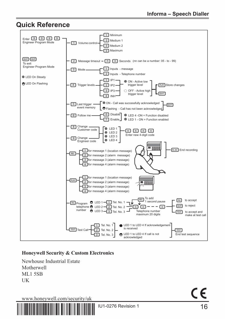
Volume control
MinimumEnterEngineer Program Mode
9 9 9 9Medium 1
Maximum
Message timeout2 n n Seconds (nn can be a number: 05 - to - 99)
Mode3 Inputs - message1
Inputs - Telephone number2
Trigger levels4ON - Active lowtrigger level
OFF - Active hightrigger level
PLAY Store changes
IP11
2
4
Follow me6
QUI T
Last triggerevent memory
5 ON - Call was successfully acknowledged
Flashing - Call has not been acknowledgedQUI T
LED 4 -ON = Function disabledLED 1 - ON = Function enabled
Disable0
Enable1
1
1
2
3
8 ChangeCustomer code n n n n
Enter new 4-digit code
LED 1LED 2LED 3LED 4
2
ChangeEngineer code
REC
QUIT
TEST
PL AY
TEL
9
1
4
3
for message 2 (alarm message)for message 1 (
for message 4 (alarm message)for message 3 (alarm message)
End recording
2PLAY
1
4
3
for message 2 (alarm message)for message 1 (location message)
for message 4 (alarm message)for message 3 (alarm message)
Programtelephonenumber
LED 1LED 2LED 3
2
1
3
nn n nTelephone numbermaximum 20 digits
to accept
to reject
to accept andmake at test call
TESTTest Call 2
1
3 End test sequence
LED 1 to LED 4 If acknowledgementis received
LED 1 to LED 4 If call is notacknowledged
Tel. No. 1Tel. No. 2Tel. No. 3
TEST
Tel. No. 1
Tel. No. 2Tel. No. 3
QUIT QUIT
To exitEngineer Program Mode
LED On Steady
LED On Flashing
3
IP2
IP3
INH
To add1 second pause
3
Medium 2
location message)
TEL
REC
Quick Reference
Honeywell Security & Custom Electronics
Newhouse Industrial Estate
Motherwell
ML1 5SB
UK
www.honeywell.com/security/uk
16IU1-0276 Revision 1
IU- revision-


