www.bio-protocol.org/e2381 Vol 7, Iss 13, Jul 05, 2017 DOI:10.21769/BioProtoc.2381
1
Spinal Cord Preparation from Adult Red-eared Turtles for Electrophysiological Recordings during Motor Activity
Peter C Petersen1, 2 and Rune W Berg1, *
1Center for Neuroscience, Faculty of Health and Medical Sciences, University of Copenhagen,
Copenhagen, Denmark; 2Current address: New York University Neuroscience Institute, New York
University, New York, New York 10016, USA
*For correspondence: [email protected]
[Abstract] Although it is known that the generation of movements is performed to a large extent in
neuronal circuits located in the spinal cord, the involved mechanisms are still unclear. The turtle as a
model system for investigating spinal motor activity has advantages, which far exceeds those of model
systems using other animals. The high resistance to anoxia allows for investigation of the fully developed
and adult spinal circuitry, as opposed to mammals, which are sensitive to anoxia and where using
neonates are often required to remedy the problems. The turtle is mechanically stable and natural
sensory inputs can induce multiple complex motor behaviors, without the need for application of
neurochemicals. Here, we provide a detailed protocol of how to make the adult turtle preparation, also
known as the integrated preparation for electrophysiological investigation. Here, the hind-limb scratch
reflex can be induced by mechanical sensory activation, while recording single cells, and the network
activity, via intracellular-, extracellular- and electroneurogram recordings. The preparation was
developed for the studies by Petersen et al. (2014) and Petersen and Berg (2016), and other ongoing
studies.
Keywords: Adult turtle, Integrated preparation, ex vivo, Spinal cord, Electrophysiology, Intracellular and
extracellular recordings, Single units, Electroneurogram, Scratch reflex, Central pattern generator
[Background] The investigation of spinal electrophysiology has traditionally been associated with
mechanical complications due to the many moving parts and the flexibility of the spine. To circumvent
this issue, the spinal cord has often been dissected out of the column and moved to a chamber where
stable electrophysiological recordings can be performed. Nevertheless, this procedure has
shortcomings, for instance, it is complicated to properly activate the motor circuitry especially if multiple
motor behaviors are to be investigated. Furthermore, the absence of blood supply and lack of oxygen
has serious ramifications on the health and integrity of the circuitry. An experimental model, which can
circumvent all these issues, is the turtle preparation (Keifer and Stein, 1983). Here, one can study not
only the fully developed vertebrate spinal cord, but also several different types of complex motor
behaviors without the need of neuro-active substances such as glutamate agonists, 5HT, and dopamine.
Since the neurons in the turtle central nervous system are able to perform anaerobic metabolism, the
integrity of the circuit remains for much longer than in the mammalian experiments. Last, the turtle
carapace organization allows stabile multi-electrode recordings of unprecedented quality. Here, we
Copyright Petersen and Berg. This article is distributed under the terms of the Creative Commons Attribution License (CC BY 4.0).
www.bio-protocol.org/e2381 Vol 7, Iss 13, Jul 05, 2017 DOI:10.21769/BioProtoc.2381
2
provide a detailed protocol for setting up the integrated adult turtle preparation, sometimes called the ex
vivo preparation (Guzulaitis et al., 2014), with intact spinal motor network. The preparation provides the
opportunity for measurements of the central pattern generator in the lumbar spinal segments (Figure 1),
which is similar to the lumbar spinal cord of mammals and other animals (Walloe et al., 2011). This
preparation includes the spinal segments D3-S2 en bloc. Measurements of the scratch reflex can be
performed entirely in the absence of chemical anesthesia. Intracellular, as well as high-density
extracellular recordings, can be acquired in the spinal cord concurrent with both ipsilateral and
contralateral electroneurogram recordings of muscle nerves (ENG). The scratch reflex is induced by
mechanically touching the ventral side of the carapace and therefore identical or close to a natural
behavior. A smaller version of the integrated turtle preparation was introduced by Keifer and Stein (1983)
and subsequently adapted and modified (Currie and Lee, 1997; Alaburda and Hounsgaard, 2003;
Alaburda et al., 2005; Berg et al., 2007 and 2008; Kolind et al., 2012; Vestergaard and Berg, 2015). The
present preparation was developed for the study by Petersen et al. (2014) and Petersen and Berg (2016)
where electrode arrays are inserted perpendicularly into the lumbar spinal cord (Berg et al., 2009). The preparation steps can be split into two parts, typically performed over two days. First part can be
performed without a microscope. All procedures of the first part are completed over 3 h. The first 2 h to
induce anesthesia and the last hour for dissection. The procedures of the second part can be performed
at a setup using a microscope and will take about an hour to complete.
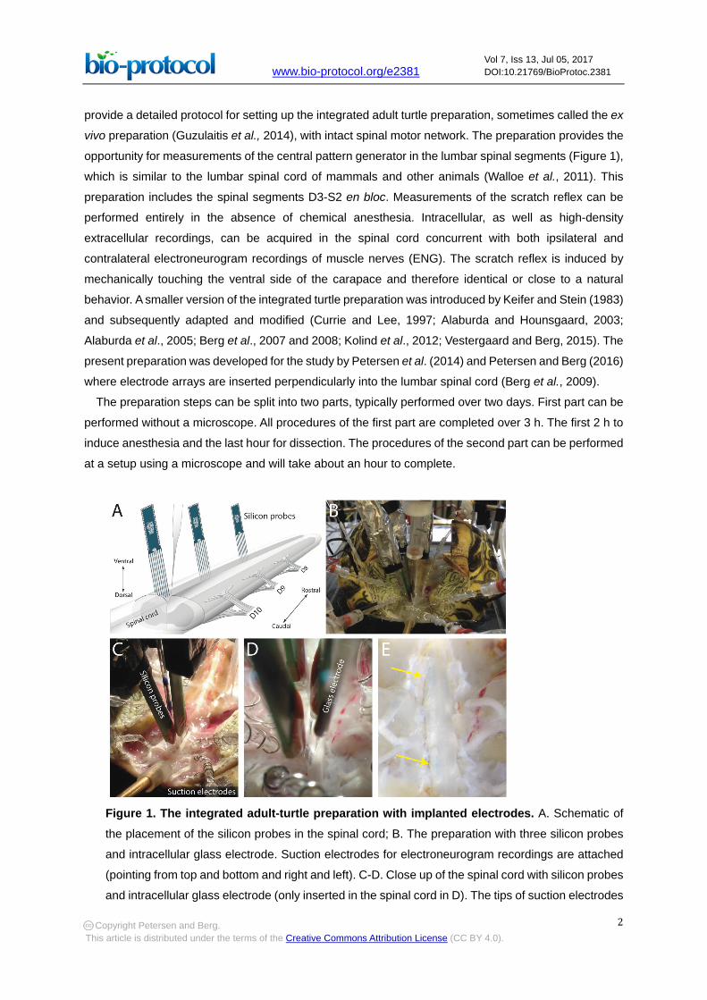
Figure 1. The integrated adult-turtle preparation with implanted electrodes. A. Schematic of
the placement of the silicon probes in the spinal cord; B. The preparation with three silicon probes
and intracellular glass electrode. Suction electrodes for electroneurogram recordings are attached
(pointing from top and bottom and right and left). C-D. Close up of the spinal cord with silicon probes
and intracellular glass electrode (only inserted in the spinal cord in D). The tips of suction electrodes
Copyright Petersen and Berg. This article is distributed under the terms of the Creative Commons Attribution License (CC BY 4.0).
www.bio-protocol.org/e2381 Vol 7, Iss 13, Jul 05, 2017 DOI:10.21769/BioProtoc.2381
3
are also visible. Modified from Petersen and Berg (2016) with permission. E. The spinal cord after
the silicon probes have been retracted. Blue DiD markings are visible from the first and third shank
(8 markings for each of the probes, highlighted with arrows).
Materials and Reagents 1. Scalpel handle #3 (Fine Science Tools, catalog number: 10003-12) with scalpel blade #15 (Fine
Science Tools, catalog number: 10015-00)
2. Cast cutter blade: BSN 2.5” stainless steel sectioned blade (BSN medical, catalog number: 480-
4183-145)
3. Plastic bag, 5 L size
4. Gloves
5. 45 mm Rotary cutter blades (WorldKitchen, OLFA, catalog number: RB45-5)
6. Cyanoacrylate adhesive (Panacol, catalog number: Cyanolit® 202)
7. Plexiglas plate: 80 x 15 x 2 mm
8. Paper towel
9. 100 mm or 120 mm Petri dishes (VWR, catalog number: HECH41042024 or HECH41042030)
10. Earmuff (PeltorTM OptimeTM 98 Earmuff) (3M, catalog number: 10093045080912)
11. Syringe needle 27 G, 31 mm (BD, catalog number: 305136)
12. Red eared turtles (Trachemys scripta elegans, Nasco, Fort Atkinson, WI, USA) of weight 300-
500 g and of both sexes were used in this procedure
13. Crushed ice
14. Sodium chloride (NaCl) (Sigma-Aldrich, catalog number: S3014)
15. Potassium chloride (KCl) (Sigma-Aldrich, catalog number: P5405)
16. Sodium bicarbonate (NaHCO3) (Sigma-Aldrich)
17. Magnesium chloride (MgCl2) (Sigma-Aldrich, catalog number: 208337)
18. Calcium chloride (CaCl2) (Sigma-Aldrich, catalog number: 21115)
19. Glucose (Sigma-Aldrich, catalog number: G7021)
20. Ringer’s solution (98% O2/2% CO2) (see Recipes)
21. Ringer’s solution (95% O2/5% CO2) (see Recipes)
Equipment
1. Scissors
Large scissors (Fine Science Tools, catalog number: 14014-17)
Fine scissors (Fine Science Tools, catalog number: 14090-09)
Fine serrated scissors (Fine Science Tools, catalog number: 14058-11)
Copyright Petersen and Berg. This article is distributed under the terms of the Creative Commons Attribution License (CC BY 4.0).
www.bio-protocol.org/e2381 Vol 7, Iss 13, Jul 05, 2017 DOI:10.21769/BioProtoc.2381
4
2. Forceps:
Dumont #5 forceps (Fine Science Tools, catalog number: 11251-10)
Dumont #5 fine forceps (Fine Science Tools, catalog number: 11254-20)
Dumont #7 curved forceps (Fine Science Tools, catalog number: 11271-30)
Toothed tissue forceps (Fine Science Tools, catalog number: 11022-15)
Serrated Graefe forceps (Fine Science Tools, catalog number: 11051-10)
3. Pliers: Liston Gross Anatomy Bone Cutters (Fine Science Tools, catalog number: 16104-19)
4. Course and fine Rongeurs: Lempert Rongeurs (Fine Science Tools, catalog number: 16004-16)
and Friedman-Pearson Rongeurs (Fine Science Tools, catalog number: 16221-14)
5. Perfusion system: Custom-designed air-pressure system/outlet connected to the inlet of a 1 L
Pyrex glass bottle with lid. The outlet of the bottle is connected to a flow meter and to a 21 G 5
mm syringe needle (BD, catalog number: 305129)
6. Cast saw cutter (Atlas International, American Orthopaedic, catalog number: T-CC-100)
7. Pyrex glass griffin beaker 1 L (Corning, PYREX®, catalog number: 1000-1L)
8. Open Plexiglas container, Dimensions: 200 x 150 x 25 mm (D x W x H), Plexiglas thickness: 3
mm. Custom built
9. Extracellular recordings: 64 channel Berg64-probe from Neuronexus. 8 shanks, each with 8
staggered recording-sites distanced 30 µm vertically, designed for ventral horn recordings from
the turtle (Neuronexus, BERG A8X8-5MM-200-160 PROBE)
10. Intracellular recordings: Glass pipettes pulled with a P-1000 Sutter Instruments and filled with a
mixture of 0.9 M potassium acetate and 0.1 M KCl. For histological verification 4% w/v biocytin
can be added to the mixture (Biocytin, Sigma-Aldrich, catalog number: B4261)
11. Nerve recordings: Electroneurogram (ENG) recordings can be performed with suction
electrodes
Procedure Note: The surgical procedures comply with Danish legislation and were approved by the controlling body
under the Ministry of Justice.
A. First part of the preparation
1. Anesthetization
To induce hypothermic analgesia, the turtle is submerged in crushed ice in a bucket. Full
induction of anesthesia takes about two hours.
2. Ringer’s solution
Prepare 2 L of cold Ringer’s solution (see Recipes) (5 °C) for the first day. Cold Ringer’s solution
is used to keep the turtle anesthetized during the preparation.
3. Initial surgery and perfusion
Tools: Toothed Tissue Forceps, large pliers, large scissors, small scissors, cast saw cutter, cast
cutter blade, perfusion system, plastic bag, gloves.
Copyright Petersen and Berg. This article is distributed under the terms of the Creative Commons Attribution License (CC BY 4.0).
www.bio-protocol.org/e2381 Vol 7, Iss 13, Jul 05, 2017 DOI:10.21769/BioProtoc.2381
5
a. Prepare perfusion-system: Fill the glass bottle with 500 ml Ringer’s solution and close the
lid. Connect the bottle to a compressed air system/outlet.
b. Turn on the compressed air and let the perfusion-system run for 30 sec with a flow above
120 ml/h as measured with the flow meter. Stop the flow.
c. Take the turtle from the ice bath. Two conditions must be met to ensure that the turtle is fully
anesthetized: 1) Its eyes must be closed and 2) No pedal withdrawal reflex response.
Proceed, when the anesthesia is confirmed.
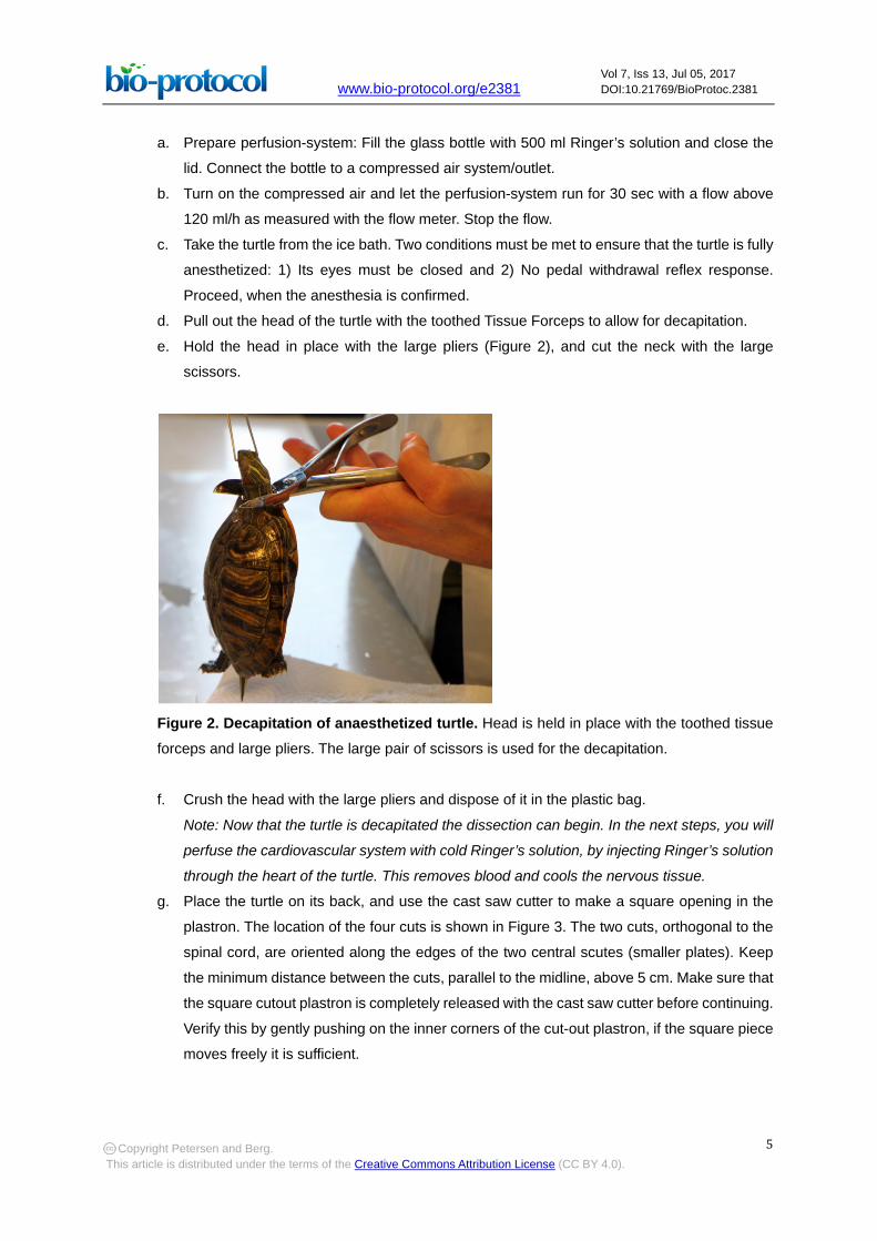
d. Pull out the head of the turtle with the toothed Tissue Forceps to allow for decapitation.
e. Hold the head in place with the large pliers (Figure 2), and cut the neck with the large
scissors.
Figure 2. Decapitation of anaesthetized turtle. Head is held in place with the toothed tissue
forceps and large pliers. The large pair of scissors is used for the decapitation.
f. Crush the head with the large pliers and dispose of it in the plastic bag.
Note: Now that the turtle is decapitated the dissection can begin. In the next steps, you will
perfuse the cardiovascular system with cold Ringer’s solution, by injecting Ringer’s solution
through the heart of the turtle. This removes blood and cools the nervous tissue.
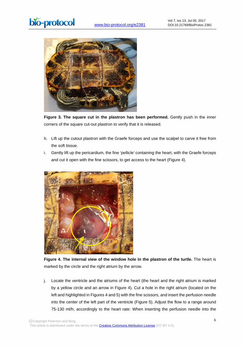
g. Place the turtle on its back, and use the cast saw cutter to make a square opening in the
plastron. The location of the four cuts is shown in Figure 3. The two cuts, orthogonal to the
spinal cord, are oriented along the edges of the two central scutes (smaller plates). Keep
the minimum distance between the cuts, parallel to the midline, above 5 cm. Make sure that
the square cutout plastron is completely released with the cast saw cutter before continuing.
Verify this by gently pushing on the inner corners of the cut-out plastron, if the square piece
moves freely it is sufficient.
Copyright Petersen and Berg. This article is distributed under the terms of the Creative Commons Attribution License (CC BY 4.0).
www.bio-protocol.org/e2381 Vol 7, Iss 13, Jul 05, 2017 DOI:10.21769/BioProtoc.2381
6
Figure 3. The square cut in the plastron has been performed. Gently push in the inner
corners of the square cut-out plastron to verify that it is released.
h. Lift up the cutout plastron with the Graefe forceps and use the scalpel to carve it free from
the soft tissue.
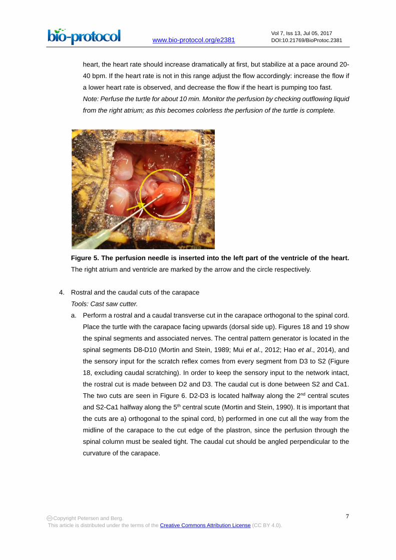
i. Gently lift up the pericardium, the fine ‘pellicle’ containing the heart, with the Graefe forceps
and cut it open with the fine scissors, to get access to the heart (Figure 4).
Figure 4. The internal view of the window hole in the plastron of the turtle. The heart is
marked by the circle and the right atrium by the arrow.
j. Locate the ventricle and the atriums of the heart (the heart and the right atrium is marked
by a yellow circle and an arrow in Figure 4). Cut a hole in the right atrium (located on the
left and highlighted in Figures 4 and 5) with the fine scissors, and insert the perfusion needle
into the center of the left part of the ventricle (Figure 5). Adjust the flow to a range around
75-130 ml/h, accordingly to the heart rate: When inserting the perfusion needle into the
Copyright Petersen and Berg. This article is distributed under the terms of the Creative Commons Attribution License (CC BY 4.0).
www.bio-protocol.org/e2381 Vol 7, Iss 13, Jul 05, 2017 DOI:10.21769/BioProtoc.2381
7
heart, the heart rate should increase dramatically at first, but stabilize at a pace around 20-
40 bpm. If the heart rate is not in this range adjust the flow accordingly: increase the flow if
a lower heart rate is observed, and decrease the flow if the heart is pumping too fast.
Note: Perfuse the turtle for about 10 min. Monitor the perfusion by checking outflowing liquid
from the right atrium; as this becomes colorless the perfusion of the turtle is complete.
Figure 5. The perfusion needle is inserted into the left part of the ventricle of the heart. The right atrium and ventricle are marked by the arrow and the circle respectively.
4. Rostral and the caudal cuts of the carapace
Tools: Cast saw cutter.
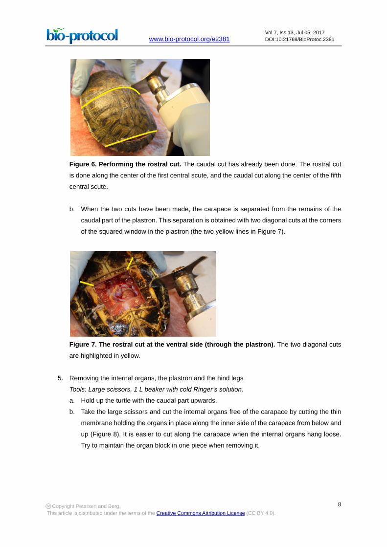
a. Perform a rostral and a caudal transverse cut in the carapace orthogonal to the spinal cord.
Place the turtle with the carapace facing upwards (dorsal side up). Figures 18 and 19 show
the spinal segments and associated nerves. The central pattern generator is located in the
spinal segments D8-D10 (Mortin and Stein, 1989; Mui et al., 2012; Hao et al., 2014), and
the sensory input for the scratch reflex comes from every segment from D3 to S2 (Figure
18, excluding caudal scratching). In order to keep the sensory input to the network intact,
the rostral cut is made between D2 and D3. The caudal cut is done between S2 and Ca1.
The two cuts are seen in Figure 6. D2-D3 is located halfway along the 2nd central scutes
and S2-Ca1 halfway along the 5th central scute (Mortin and Stein, 1990). It is important that
the cuts are a) orthogonal to the spinal cord, b) performed in one cut all the way from the
midline of the carapace to the cut edge of the plastron, since the perfusion through the
spinal column must be sealed tight. The caudal cut should be angled perpendicular to the
curvature of the carapace.
Copyright Petersen and Berg. This article is distributed under the terms of the Creative Commons Attribution License (CC BY 4.0).
www.bio-protocol.org/e2381 Vol 7, Iss 13, Jul 05, 2017 DOI:10.21769/BioProtoc.2381
8
Figure 6. Performing the rostral cut. The caudal cut has already been done. The rostral cut
is done along the center of the first central scute, and the caudal cut along the center of the fifth
central scute.
b. When the two cuts have been made, the carapace is separated from the remains of the
caudal part of the plastron. This separation is obtained with two diagonal cuts at the corners
of the squared window in the plastron (the two yellow lines in Figure 7).
Figure 7. The rostral cut at the ventral side (through the plastron). The two diagonal cuts
are highlighted in yellow.
5. Removing the internal organs, the plastron and the hind legs
Tools: Large scissors, 1 L beaker with cold Ringer’s solution. a. Hold up the turtle with the caudal part upwards.
b. Take the large scissors and cut the internal organs free of the carapace by cutting the thin
membrane holding the organs in place along the inner side of the carapace from below and
up (Figure 8). It is easier to cut along the carapace when the internal organs hang loose.
Try to maintain the organ block in one piece when removing it.
Copyright Petersen and Berg. This article is distributed under the terms of the Creative Commons Attribution License (CC BY 4.0).
www.bio-protocol.org/e2381 Vol 7, Iss 13, Jul 05, 2017 DOI:10.21769/BioProtoc.2381
9
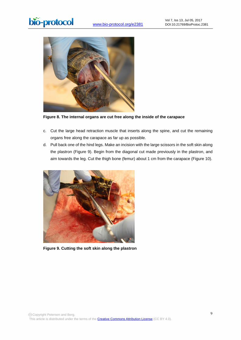
Figure 8. The internal organs are cut free along the inside of the carapace
c. Cut the large head retraction muscle that inserts along the spine, and cut the remaining
organs free along the carapace as far up as possible.
d. Pull back one of the hind legs. Make an incision with the large scissors in the soft skin along
the plastron (Figure 9). Begin from the diagonal cut made previously in the plastron, and
aim towards the leg. Cut the thigh bone (femur) about 1 cm from the carapace (Figure 10).
Figure 9. Cutting the soft skin along the plastron
Copyright Petersen and Berg. This article is distributed under the terms of the Creative Commons Attribution License (CC BY 4.0).

www.bio-protocol.org/e2381 Vol 7, Iss 13, Jul 05, 2017 DOI:10.21769/BioProtoc.2381
10
Figure 10. Cutting the thigh bone
e. Repeat step A5d for the other hind leg.
f. Cut the plastron and the caudal end of the carapace free without damaging the spinal cord.
The preparation is now left in a Petri dish in cold Ringer’s solution (Figure 11).
Figure 11. The preparation lying in a Petri dish without plastron and legs
g. Clean off excessive blood from the preparation by quickly rinsing it in cold Ringer’s solution
(about 50 ml) and place it in a 1 L beaker with cold Ringer’s solution when done.
6. Clear the spinal column
Tools: Graefe forceps, curved forceps, scalpel.
The muscles and connective tissue covering the vertebra has to be removed carefully with a
scalpel and forceps. The muscles tissue is carefully scraped off until the vertebra is fully exposed
while leaving the nerves intact (Figure 12A).
Copyright Petersen and Berg. This article is distributed under the terms of the Creative Commons Attribution License (CC BY 4.0).
www.bio-protocol.org/e2381 Vol 7, Iss 13, Jul 05, 2017 DOI:10.21769/BioProtoc.2381
11
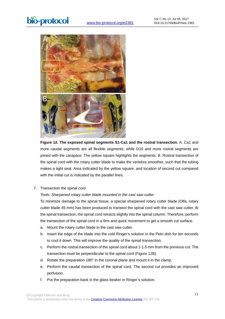
Figure 12. The exposed spinal segments S1-Ca1 and the rostral transection. A. Ca1 and
more caudal segments are all flexible segments, while D10 and more rostral segments are
joined with the carapace. The yellow square highlights the segments. B. Rostral transection of
the spinal cord with the rotary cutter blade to make the vertebra smoother, such that the tubing
makes a tight seal. Area indicated by the yellow square, and location of second cut compared
with the initial cut is indicated by the parallel lines.
7. Transection the spinal cord
Tools: Sharpened rotary cutter blade mounted in the cast saw cutter.
To minimize damage to the spinal tissue, a special sharpened rotary cutter blade (Olfa, rotary
cutter blade 45 mm) has been produced to transect the spinal cord with the cast saw cutter. At
the spinal transection, the spinal cord retracts slightly into the spinal column. Therefore, perform
the transection of the spinal cord in a firm and quick movement to get a smooth cut surface.
a. Mount the rotary cutter blade in the cast saw cutter.
b. Insert the edge of the blade into the cold Ringer’s solution in the Petri dish for ten seconds
to cool it down. This will improve the quality of the spinal transection.
c. Perform the rostral transection of the spinal cord about 1-1.5 mm from the previous cut. The
transection must be perpendicular to the spinal cord (Figure 12B).
d. Rotate the preparation 180° in the coronal plane and mount it in the clamp.
e. Perform the caudal transection of the spinal cord. The second cut provides an improved
perfusion.
f. Put the preparation back in the glass beaker in Ringer’s solution.
Copyright Petersen and Berg. This article is distributed under the terms of the Creative Commons Attribution License (CC BY 4.0).
www.bio-protocol.org/e2381 Vol 7, Iss 13, Jul 05, 2017 DOI:10.21769/BioProtoc.2381
12
8. Attaching the Plexiglas plate to the preparation
Tools: Cyanoacrylate adhesive, Plexiglas plate, Petri dish with lid, ice, scalpel, perfusion system,
paper towel. a. Put a layer of ice in the largest Petri dish and place the smaller Petri dish on top of the ice,
facing upwards, and fill it with cold Ringer’s solution.
b. Place the preparation in the cold Ringer’s solution with the rostral end facing upwards.
c. Dry the cut rostral carapace edge with a paper towel.
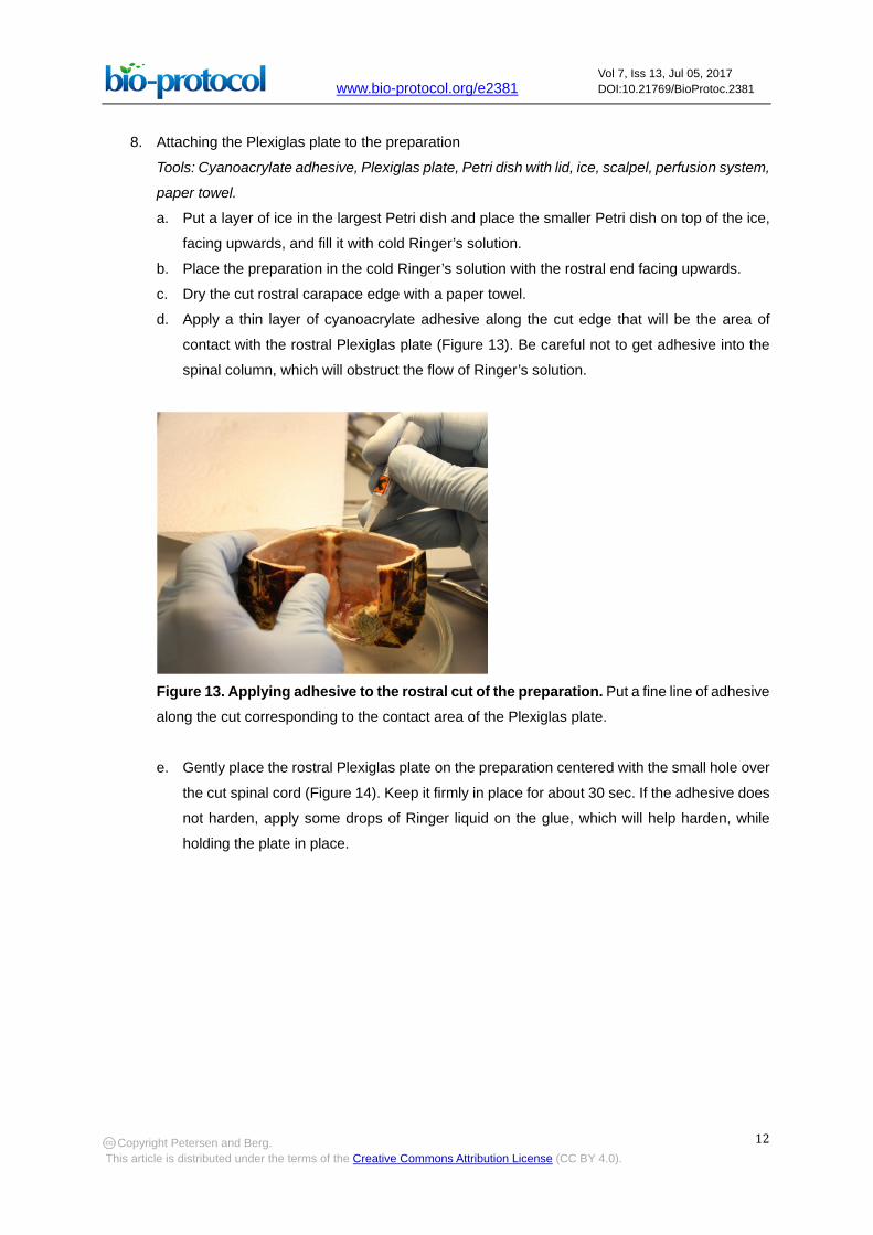
d. Apply a thin layer of cyanoacrylate adhesive along the cut edge that will be the area of
contact with the rostral Plexiglas plate (Figure 13). Be careful not to get adhesive into the
spinal column, which will obstruct the flow of Ringer’s solution.
Figure 13. Applying adhesive to the rostral cut of the preparation. Put a fine line of adhesive
along the cut corresponding to the contact area of the Plexiglas plate.
e. Gently place the rostral Plexiglas plate on the preparation centered with the small hole over
the cut spinal cord (Figure 14). Keep it firmly in place for about 30 sec. If the adhesive does
not harden, apply some drops of Ringer liquid on the glue, which will help harden, while
holding the plate in place.
Copyright Petersen and Berg. This article is distributed under the terms of the Creative Commons Attribution License (CC BY 4.0).
www.bio-protocol.org/e2381 Vol 7, Iss 13, Jul 05, 2017 DOI:10.21769/BioProtoc.2381
13
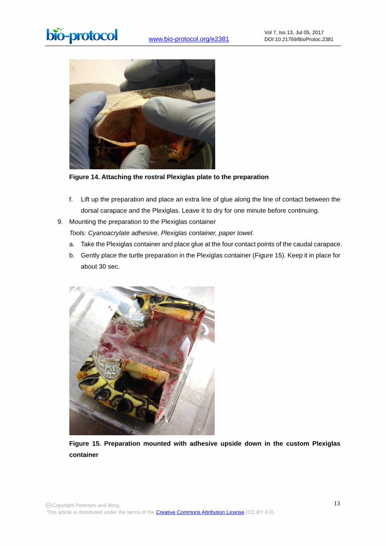
Figure 14. Attaching the rostral Plexiglas plate to the preparation
f. Lift up the preparation and place an extra line of glue along the line of contact between the
dorsal carapace and the Plexiglas. Leave it to dry for one minute before continuing.
9. Mounting the preparation to the Plexiglas container
Tools: Cyanoacrylate adhesive, Plexiglas container, paper towel. a. Take the Plexiglas container and place glue at the four contact points of the caudal carapace.
b. Gently place the turtle preparation in the Plexiglas container (Figure 15). Keep it in place for
about 30 sec.
Figure 15. Preparation mounted with adhesive upside down in the custom Plexiglas container
Copyright Petersen and Berg. This article is distributed under the terms of the Creative Commons Attribution License (CC BY 4.0).
www.bio-protocol.org/e2381 Vol 7, Iss 13, Jul 05, 2017 DOI:10.21769/BioProtoc.2381
14
c. Gently fill the Plexiglas container with Ringer’s solution. The liquid will help harden the
adhesive.
d. Place the preparation in a larger plastic container and immerse it completely in Ringer’s
solution.
e. The procedures of the first part are now complete. Leave the preparation overnight in a
refrigerator.
B. Second part of the preparation
1. Setup the spinal vertebral foramen perfusion
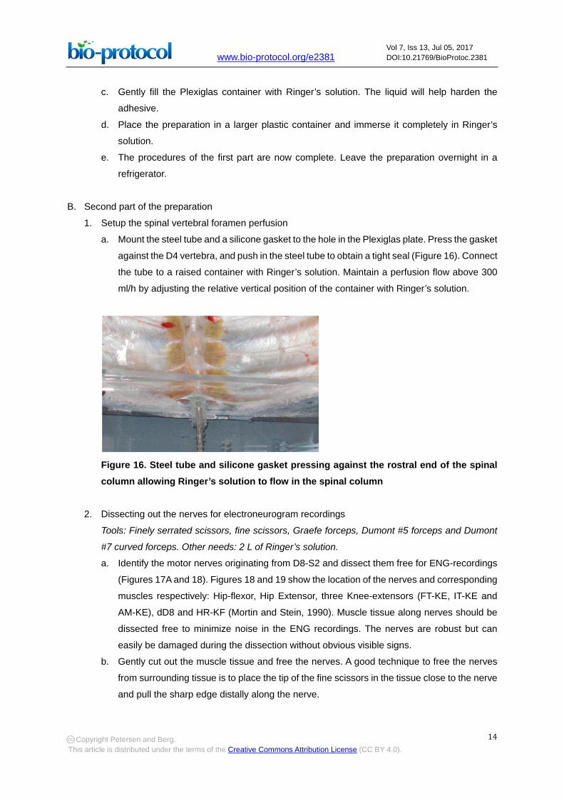
a. Mount the steel tube and a silicone gasket to the hole in the Plexiglas plate. Press the gasket
against the D4 vertebra, and push in the steel tube to obtain a tight seal (Figure 16). Connect
the tube to a raised container with Ringer’s solution. Maintain a perfusion flow above 300
ml/h by adjusting the relative vertical position of the container with Ringer’s solution.
Figure 16. Steel tube and silicone gasket pressing against the rostral end of the spinal column allowing Ringer’s solution to flow in the spinal column
2. Dissecting out the nerves for electroneurogram recordings
Tools: Finely serrated scissors, fine scissors, Graefe forceps, Dumont #5 forceps and Dumont
#7 curved forceps. Other needs: 2 L of Ringer’s solution. a. Identify the motor nerves originating from D8-S2 and dissect them free for ENG-recordings
(Figures 17A and 18). Figures 18 and 19 show the location of the nerves and corresponding
muscles respectively: Hip-flexor, Hip Extensor, three Knee-extensors (FT-KE, IT-KE and
AM-KE), dD8 and HR-KF (Mortin and Stein, 1990). Muscle tissue along nerves should be
dissected free to minimize noise in the ENG recordings. The nerves are robust but can
easily be damaged during the dissection without obvious visible signs.
b. Gently cut out the muscle tissue and free the nerves. A good technique to free the nerves
from surrounding tissue is to place the tip of the fine scissors in the tissue close to the nerve
and pull the sharp edge distally along the nerve.
Copyright Petersen and Berg. This article is distributed under the terms of the Creative Commons Attribution License (CC BY 4.0).
www.bio-protocol.org/e2381 Vol 7, Iss 13, Jul 05, 2017 DOI:10.21769/BioProtoc.2381
15
Note: Figures 1B-1E show the finished preparation, mounted in the Plexiglas container and
immersed in Ringer’s solution. The nerves dissected free are clearly visible as white
branches originating at the spinal cord and going towards the hind limb muscles. Glass
electrodes are used for the ENG recordings. Apply a slight negative pressure, and prepare
the glass opening to fit the respective nerves you want to record.
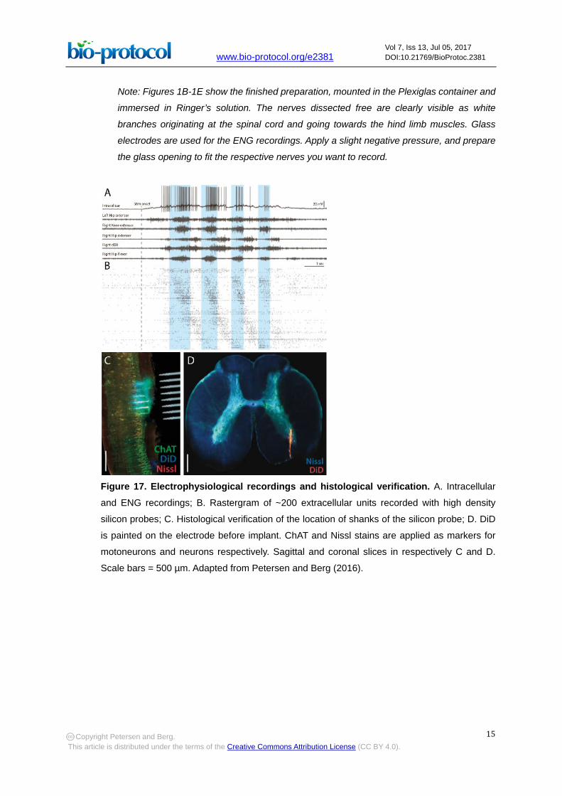
Figure 17. Electrophysiological recordings and histological verification. A. Intracellular
and ENG recordings; B. Rastergram of ~200 extracellular units recorded with high density
silicon probes; C. Histological verification of the location of shanks of the silicon probe; D. DiD
is painted on the electrode before implant. ChAT and Nissl stains are applied as markers for
motoneurons and neurons respectively. Sagittal and coronal slices in respectively C and D.
Scale bars = 500 µm. Adapted from Petersen and Berg (2016).
Copyright Petersen and Berg. This article is distributed under the terms of the Creative Commons Attribution License (CC BY 4.0).

www.bio-protocol.org/e2381 Vol 7, Iss 13, Jul 05, 2017 DOI:10.21769/BioProtoc.2381
16
Figure 18. The sensory and motor nerves along the spinal cord. Adapted from Petersen et
al. (2014) with permission.
Figure 19. Major muscle groups of the hind-limb. Hip flexor, Hip Extensor, Knee Extensors
(FT-KE, IT-KE, AM-KE) and Knee flexor (HR-KF, extend across both the hip- and the knee-joint).
Reproduced from Bakker and Crowe (1982) with permission.
3. Preparation for extracellular and intracellular recordings
Tools: Fine forceps, fine Rongeur, fine scalpel, syringe needle tip (size: 27 G). Using the fine Rongeur, open the spinal column on the ventral side along the segments D8-D10.
Gently remove the dura mater with scalpel and forceps. For each insertion site for the silicon
probes, open the pia mater with longitudinal cuts along the spinal cord with the tip of a bent
syringe needle tip (size 27 G). Perform the cuts parallel to the ventral horn between the ventral
roots, as superficial as possible (Figure 1E). This completes the procedures to make the
Copyright Petersen and Berg. This article is distributed under the terms of the Creative Commons Attribution License (CC BY 4.0).
www.bio-protocol.org/e2381 Vol 7, Iss 13, Jul 05, 2017 DOI:10.21769/BioProtoc.2381
17
integrated preparation. Figure 17 shows example electrophysiological recordings and histology
(Petersen and Berg, 2016).
Recipes
1. Ringer’s solution (98% O2/2% CO2)
120 mM NaCl
5 mM KCl
15 mM NaHCO3
2 mM MgCl2
3 mM CaCl2
20 mM glucose
Demineralized water
The solution is saturated with 98% O2/2% CO2, by aeration for 30 min to obtain pH level of 7.6
2. Ringer’s solution (95% O2/5% CO2)
100 mM NaCl
5 mM KCl
30 mM NaHCO3
2 mM MgCl2
3 mM CaCl2
10 mM glucose
Demineralized water
The solution is saturated with 95% O2/5% CO2, by aeration for 30 min to obtain pH level of 7.6
Note: Either Ringer’s solutions can be used in this protocol.
Acknowledgments
Funded by the Novo Nordisk Foundation (RB), the Danish Council for Independent Research
Medical Sciences (RB and PP) and the Dynamical Systems Interdisciplinary Network, University of
Copenhagen. Thanks to J. K. Dreyer and J. Hounsgaard for reading and commenting an earlier
version of the manuscript.
References
1. Alaburda, A. and Hounsgaard, J. (2003). Metabotropic modulation of motoneurons by scratch-
like spinal network activity. J Neurosci 23(25): 8625-8629.
2. Alaburda, A., Russo, R., MacAulay, N. and Hounsgaard, J. (2005). Periodic high-conductance
states in spinal neurons during scratch-like network activity in adult turtles. J Neurosci 25(27):
6316-6321.
Copyright Petersen and Berg. This article is distributed under the terms of the Creative Commons Attribution License (CC BY 4.0).

www.bio-protocol.org/e2381 Vol 7, Iss 13, Jul 05, 2017 DOI:10.21769/BioProtoc.2381
18
3. Bakker, J. G. M. and Crowe, A. (1982). Multicyclic scratch reflex movements in the terrapin
Pseudemys scripta elegans. J Comp Physiol 145:477-484.
4. Berg, R. W., Alaburda, A. and Hounsgaard, J. (2007). Balanced inhibition and excitation drive
spike activity in spinal half-centers. Science 315(5810): 390-393.
5. Berg, R. W., Chen M. T., Huang, H. C., Hsiao, M. C. and Cheng, H. (2009). A method for unit
recording in the lumbar spinal cord during locomotion of the conscious adult rat. J Neurosci
Methods 182(1): 49-54.
6. Berg, R. W., Ditlevsen, S. and Hounsgaard, J. (2008). Intense synaptic activity enhances
temporal resolution in spinal motoneurons. PLoS One 3(9): e3218.
7. Currie, S. N. and Lee, S. (1997). Glycinergic inhibition contributes to the generation of rostral
scratch motor patterns in the turtle spinal cord. J Neurosci 17(9): 3322-3333.
8. Guzulaitis, R., Alaburda, A. and Hounsgaard, J. (2014). Dense distributed processing in a
hindlimb scratch motor network. J Neurosci 34(32): 10756-10764.
9. Hao, Z. Z., Meier, M. L. and Berkowitz, A. (2014). Rostral spinal cord segments are sufficient to
generate a rhythm for both locomotion and scratching but affect their hip extensor phases
differently. J Neurophysiol 112(1): 147-155.
10. Keifer, J. and Stein, P. S. (1983). In vitro motor program for the rostral scratch reflex generated
by the turtle spinal cord. Brain Res 266(1): 148-151.
11. Kolind, J., Hounsgaard, J. and Berg, R. W. (2012). Opposing effects of intrinsic conductance
and correlated synaptic input on Vm-fluctuations during network activity. Front Comput Neurosci
6: 40.
12. Mortin, L. I. and Stein, P. S. (1989). Spinal cord segments containing key elements of the central
pattern generators for three forms of scratch reflex in the turtle. J Neurosci 9(7): 2285-2296.
13. Mortin, L. I. and Stein, P. S. (1990). Cutaneous dermatomes for initiation of three forms of the
scratch reflex in the spinal turtle. J Comp Neurol 295(4): 515-529.
14. Mui, J. W., Willis, K. L., Hao, Z. Z. and Berkowitz, A. (2012). Distributions of active spinal cord
neurons during swimming and scratching motor patterns. J Comp Physiol A Neuroethol Sens
Neural Behav Physiol 198(12): 877-889.
15. Petersen, P. C. and Berg. R. W. (2016). Lognormal firing rate distribution reveals prominent
fluctuation-driven regime in spinal motor networks. eLife 18805.
16. Petersen, P. C., Vestergaard, M., Jensen, K. H. and Berg, R. W. (2014). Premotor spinal
network with balanced excitation and inhibition during motor patterns has high resilience to
structural division. J Neurosci 34(8): 2774-2784.
17. Vestergaard, M. and Berg, R. W. (2015). Divisive gain modulation of motoneurons by inhibition
optimizes muscular control. J Neurosci 35(8): 3711-3723.
18. Walloe, S., Nissen, U. V., Berg, R. W., Hounsgaard, J. and Pakkenberg, B. (2011). Stereological
estimate of the total number of neurons in spinal segment D9 in the red-eared turtle. J Neurosci
31(7): 2431-2435.
Copyright Petersen and Berg. This article is distributed under the terms of the Creative Commons Attribution License (CC BY 4.0).


