
ORIGINAL ARTICLE
Springback Mechanism Analysis and Experiments on RoboticBending of Rectangular Orthodontic Archwire
Jin-Gang Jiang1 • Ying-Shuai Han1 • Yong-De Zhang1 • Yan-Jv Liu1,2 •
Zhao Wang1 • Yi Liu3
Received: 21 May 2016 / Revised: 9 April 2017 / Accepted: 20 April 2017 / Published online: 15 May 2017
� Chinese Mechanical Engineering Society and Springer-Verlag Berlin Heidelberg 2017
Abstract Fixed-appliance technology is the most common
and effective malocclusion orthodontic treatment method,
and its key step is the bending of orthodontic archwire. The
springback of archwire did not consider the movement of the
stress-strain-neutral layer. To solve this problem, a spring-
back calculation model for rectangular orthodontic archwire
is proposed. A bending springback experiment is conducted
using an orthodontic archwire bending springback mea-
surement device. The springback experimental results show
that the theoretical calculation results using the proposed
model coincide better with the experimental testing results
than when movement of the stress-strain-neutral layer was
not considered. A bending experiment with rectangular
orthodontic archwire is conducted using a robotic
orthodontic archwire bending system. The patient expriment
result show that the maximum and minimum error ratios of
formed orthodontic archwire parameters are 22.46% and
10.23% without considering springback and are decreased to
11.35% and 6.13% using the proposed model. The proposed
springback calculation model, which considers the move-
ment of the stress-strain-neutral layer, greatly improves the
orthodontic archwire bending precision.
Keywords Robotic bending � Rectangular orthodontic
archwire � Springback mechanism � Stress-strain-neutral
layer
1 Introduction
Malocclusion is a common oral disease, and is currently
the third-largest oral disease responsible for harming peo-
ple’s health. Its main features are irregular tooth alignment,
abnormal tooth-jaw relations between the upper and lower
dental arches, and abnormal size, morphology, and location
of the jaw. In China, the malocclusion incidence in ado-
lescents and children is up to 52.8%–72.9%. This not only
affects appearance, dentofacial growth, craniofacial mor-
phology, and oral function, but also generates negative
effects when those affected apply for jobs, search for
mates, and vie for promotions. Moreover, it is likely to
cause indigestion and gastrointestinal disease owing to
reduced masticatory function, and it also causes psycho-
logical damage [1–4]. Fixed-appliance technology is the
most common and effective malocclusion orthodontic
treatment method, and its key step is the bending of
orthodontic archwire [5, 6]. Because of archwire hypere-
lasticity, complexity of formed archwire shapes, and the
uncertainty of manual operation, it is difficult to realize
personalized archwire bending. Orthodontic specialists
often require a long period of time for to be trained for
archwire bending in order to achieve a high standard of
orthodontic treatment [7, 8]. Different orthodontic arch-
wires have different elastic moduli. Nonlinear stress-strain
Supported by National Natural Science Foundation of China (Grant
Nos. 51205093, 61403222), China Postdoctoral Science Foundation
(Grant No. 2016M591538), Heilongjiang Postdoctoral Science
Foundation (Grant No. LBH-Z16091), and Science Funds for the
Young Innovative Talents of Harbin University of Science and
Technology (Grant No. 201509)
& Jin-Gang Jiang
1 Robotics and Its Engineering Research Center, Harbin
University of Science and Technology, Harbin 150080, China
2 Computing Center, Qiqihar University, Qiqihar 161000,
China
3 Department of Orthodontics, Peking University Hospital of
Stomatology, Beijing 100081, China
123
Chin. J. Mech. Eng. (2017) 30:1406–1415
https://doi.org/10.1007/s10033-017-0142-0
archwires are difficult to be bent accurately by manual
operation. Additionally, the bending process is time-con-
suming, and the archwires have low bending accuracy. The
traditional manual method for bending archwire using
personal medical experience will be changed once robotic
orthodontic archwire bending systems are manufactured;
this will greatly improve the efficiency and accuracy of
orthodontic archwire bending [9, 10]. Suresmile Corpora-
tion has taken the lead in automatic orthodontic archwire
bending, and the orthodontic archwire bending robot is
emerging at the right moment [11, 12]. In the process of
archwire bending using a robot, springback of the
orthodontic archwire is generated because of the hypere-
lasticity and high-strength of the orthodontic archwire.
Bending springback seriously affects the accuracy of
orthodontic archwire bending.
Numerous domestic and foreign research institutions
have performed research into archwire bending springback
and achieved useful results [13–16]. The bending proper-
ties of Ti-Ni-Cu alloy castings is investigated in a three-
point bending test for orthodontic applications in relation to
phase transformation. A special three-point bending fixture
is invented to determine superelastic properties in simu-
lated clinical conditions, where wire samples is held in a
fixture similar to an oral cavity [17]. Static and cyclic load-
deflection characteristics of Ni-Ti orthodontic archwires
are studied through three-point bending tests. Superelastic
behavior is investigated by focusing on bending time,
temperature, and the number of cycles, which affects the
energy dissipation capacity [18]. Surface morphology and
mechanical properties have been studied for various sizes
and tempers of Australian archwires [19]. Torque charac-
teristics of Ni-Ti and steel orthodontic archwires sustaining
a pure bending moment have been compared [20]. Three-
dimensional finite element models of superelastic nickel-
titanium orthodontic wires with a Gibbs-potential-based
formulation and thermodynamic principles have been
established, and a bending test was simulated to study the
force variation of an orthodontic Ni-Ti archwire when
loaded up to the deflection of 3 mm [21]. The load/de-
flection ratios of the heat-activated Ni-Ti orthodontic wires
of dimensions 0.014 inch 9 0.025 inch and 0.016 inch 9
0.022 inch have been compared [22, 23]. The rigidity,
elasticity, strength, and fatigue properties of five
orthodontic wires (Australian orthodontic wire, Elgiloy
yellow wire from RMO, Chinese orthodontic wire, Chinese
stainless steel wire, and heated Chinese stainless steel wire)
were tested and compared [24]. The elemental components,
surface characteristics, and mechanical properties of beta-
titanium alloy wires, Ni-Ti wires, and stainless steel wires
were compared. EDAX and SUPRATM 55 SEM equip-
ment were used to analyze components and surface char-
acteristics. A Nano Indenter XP was used to test the
elasticity modulus and hardness of the wires. Three-point
bending tests were performed to compare mechanical
properties using Instron 5848 equipment [25–27]. How-
ever, all of the above–mentioned efforts studied mechani-
cal properties and bending springback of orthodontic
archwire, while none have considered the effects of neutral
plane movement on bending springback.
Focusing on the springback problem of bending
orthodontic archwire using robotics, mechanism analysis
and calculation of springback were studied here considering
neutral plane movement in the process of bending rectan-
gular orthodontic archwire. A bending springback experi-
ment was conducted using a springback measurement
device for orthodontic archwire. The oral parameters of one
patient were selected, and a bending experiment on rectan-
gular orthodontic archwire was conducted using the pro-
posed robotic orthodontic archwire bending system.
Research on the springback mechanism of orthodontic
archwire will greatly improve the orthodontic archwire
bending precision when using robotic bending. The tradi-
tional manual method for bending archwire using personal
medical experience will be improved upon by the intro-
duction of robotic orthodontic archwire bending systems,
which not only meet physiological function and aesthetic
requirements for malocclusion patients, but also realize
quantification, standardization, and automation of forming
orthodontic archwire. This will improve bending efficiency
and accuracy and promote the development of orthodontics.
2 Springback mechanism analysis for rectangularorthodontic archwire
2.1 Springback analysis of the bending process
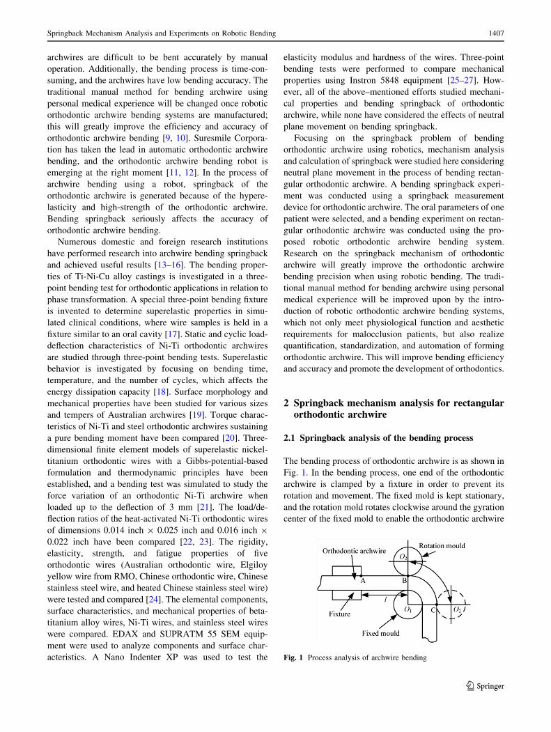
The bending process of orthodontic archwire is as shown in
Fig. 1. In the bending process, one end of the orthodontic
archwire is clamped by a fixture in order to prevent its
rotation and movement. The fixed mold is kept stationary,
and the rotation mold rotates clockwise around the gyration
center of the fixed mold to enable the orthodontic archwire
Fig. 1 Process analysis of archwire bending
Springback Mechanism Analysis and Experiments on Robotic Bending 1407
123
to take shape. After the rotation mold rotates counter-
clockwise and the load is removed, springback of the
orthodontic archwire is generated due to elastic deforma-
tion. The process of archwire bending consists of parts BC
and AB. The BC part forms the orthodontic archwire,
which is in an elastic-plastic deformation state. The AB
part is affected by the bending moment of the BC part,
inevitably generating bending deformation, and is in an
elastic deformation state.
In order to simplify the calculation process, on the
premise of guaranteed theoretical analysis validity, when
analyzing the bending springback of orthodontic archwire,
the following basic assumptions were adopted.
(1) The material of orthodontic archwire is composed of
a continuous medium. It is uniformly distributed and
isotropic, and the Bauschinger effect of the material
is ignored.
(2) In the bending process, the cross section perpendic-
ular to the center axis of the archwire is a plane
before and after bending, and the cross section is not
subject to distortion.
(3) In the bending process, the strain-hardening law for
material between the lateral tensile part and the inner
compression part is the same. Moreover, the plastic
deformation of the material does not cause the
volume to change.
On the basis of the classical formation theory, in the
initial phase of bending, the bending angle and the spring-
back angle increase with the increase of the bending moment
because of the small load torque. At this stage, the elastic
deformation is clearly greater than the plastic deformation.
Hence, this is the elastic bending stage. When the bending
moment increases to a certain extent, the bending angle no
longer changes with the bending moment. That is, while the
bending angle increases, the bending moment remains
unchanged. The plastic deformation is then clearly greater
than the elastic deformation; hence, this is the plastic
bending stage.
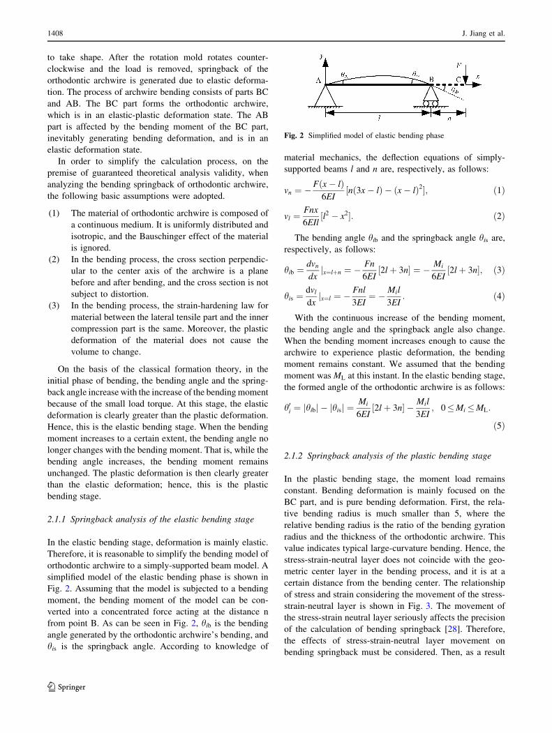
2.1.1 Springback analysis of the elastic bending stage
In the elastic bending stage, deformation is mainly elastic.
Therefore, it is reasonable to simplify the bending model of
orthodontic archwire to a simply-supported beam model. A
simplified model of the elastic bending phase is shown in
Fig. 2. Assuming that the model is subjected to a bending
moment, the bending moment of the model can be con-
verted into a concentrated force acting at the distance n
from point B. As can be seen in Fig. 2, hib is the bending
angle generated by the orthodontic archwire’s bending, and
his is the springback angle. According to knowledge of
material mechanics, the deflection equations of simply-
supported beams l and n are, respectively, as follows:
vn ¼ �Fðx� lÞ6EI
½nð3x� lÞ � ðx� lÞ2�; ð1Þ
vl ¼Fnx
6EIl½l2 � x2�: ð2Þ
The bending angle hib and the springback angle his are,
respectively, as follows:
hib ¼ dvn
dxx¼lþnj ¼ � Fn
6EI½2lþ 3n� ¼ � Mi
6EI½2lþ 3n�; ð3Þ
his ¼dvl
dxx¼lj ¼ � Fnl
3EI¼ �Mil
3EI: ð4Þ
With the continuous increase of the bending moment,
the bending angle and the springback angle also change.
When the bending moment increases enough to cause the
archwire to experience plastic deformation, the bending
moment remains constant. We assumed that the bending
moment was ML at this instant. In the elastic bending stage,
the formed angle of the orthodontic archwire is as follows:
h0i ¼ jhibj � jhisj ¼Mi
6EI½2lþ 3n� � Mil
3EI; 0�Mi �ML:
ð5Þ
2.1.2 Springback analysis of the plastic bending stage
In the plastic bending stage, the moment load remains
constant. Bending deformation is mainly focused on the
BC part, and is pure bending deformation. First, the rela-
tive bending radius is much smaller than 5, where the
relative bending radius is the ratio of the bending gyration
radius and the thickness of the orthodontic archwire. This
value indicates typical large-curvature bending. Hence, the
stress-strain-neutral layer does not coincide with the geo-
metric center layer in the bending process, and it is at a
certain distance from the bending center. The relationship
of stress and strain considering the movement of the stress-
strain-neutral layer is shown in Fig. 3. The movement of
the stress-strain neutral layer seriously affects the precision
of the calculation of bending springback [28]. Therefore,
the effects of stress-strain-neutral layer movement on
bending springback must be considered. Then, as a result
Fig. 2 Simplified model of elastic bending phase
1408 J. Jiang et al.
123

of the large strain of the orthodontic archwire in the
bending process, real stress and strain data must be used to
calculate the bending springback.
We assumed that a is the deflection distance between the
stress-strain-neutral layer and the geometric center layer
and that y is the distance between any fibrous layer and the
geometric center layer in the archwire. h is the height of
archwire. R is the curvature radius of geometric center
layer before the removal of the load, R1 is the curvature
radius of the inner side of archwire, R2is the curvature
radius of the outer side of archwire, ML is the loading
bending moment. The engineering strain of the fibrous
layer before the removal of the load is as follows:
�e ¼ l2 � l1
l1¼ hðqþ yÞ � hq
hq¼ y
q; ð6Þ
where �e is the strain of the fibrous layer before the removal
of the load, l2 is the length of the stress-strain-neutral layer
before the removal of the load, l1 is the length of the fibrous
layer before the removal of the load, q is the curvature
radius of the stress-strain-neutral layer before the removal
of the load, and h is the bending angle.
Similarly, the engineering strain of the fibrous layer
after the removal of the load is as follows:
�e0 ¼ l02 � l01l01
¼ h0ðq0 þ yÞ � h0q0
h0q0¼ y
q0; ð7Þ
where �e0 is the strain of the fibrous layer after the removal
of the load, l02 is the length of stress-strain-neutral layer
after the removal of the load, l01 is the length of the fibrous
layer after the removal of the load, q0 is the curvature
radius of stress-strain neutral layer after the removal of the
load, h0 is the formed angle after the springback of the
orthodontic archwire.
The strain difference De of the fibrous layer before and
after the removal of the load is as follows:
De ¼ �e� �e0 ¼ y � 1
q� 1
q0
� �: ð8Þ
De is a small strain with large deformation, and its
stress-strain relationship behaves according to Hooke’s
law. Therefore, the stress of the fibrous layer with the
removal of the load is as follows:
r ¼ E � De ¼ E � y � 1
q� 1
q0
� �: ð9Þ
The unloading bending moment is as follow:
MU ¼ZA
r � ydA ¼ZA
E � y2 � 1
q� 1
q0
� �dA: ð10Þ
In the loading procedure, on the basis of material
stretching tests, the stress-strain relationship for rectangular
orthodontic archwire can be obtained using the polynomial
fitting method. Therefore, the loading bending moment is
as follows:
ML ¼ZA
rð�eÞ � ydA: ð11Þ
Springback and bending are reverse processes.
Orthodontic archwire is in a free state after the removal of
the load. That is, orthodontic archwire is in a state without
a bending moment. Therefore,
MU ¼ ML: ð12Þ
That isZA
E � y2 � 1
q� 1
q0
� �dA ¼
ZA
rð�eÞ � ydA: ð13Þ
In the bending process, according to the fixed length prin-
ciple of the stress-strain-neutral layer, the following holds:
qh ¼ q0h0: ð14Þ
The springback angle and the formed angle in the plastic
bending stage can be calculated by the synthesis of
Eqs. (10)–(14). The key to the solution is the calculation of
the curvature radius, the unloading bending moment, and
Fig. 3 Relationship of stress and strain considering the movement of
the stress-strain-neutral layer
Springback Mechanism Analysis and Experiments on Robotic Bending 1409
123
the loading bending moment of the stress-strain-neutral
layer.
2.2 Curvature radius of the stress-strain-neutral
layer
In the bending process, the stress-strain-neutral layer
moves a certain distance towards to the bending center.
Hence, the curvature radius of the stress-strain-neutral
layer is not equal to the sum of the radii of the fixed mold
and the half-thickness of orthodontic archwire; rather, it is
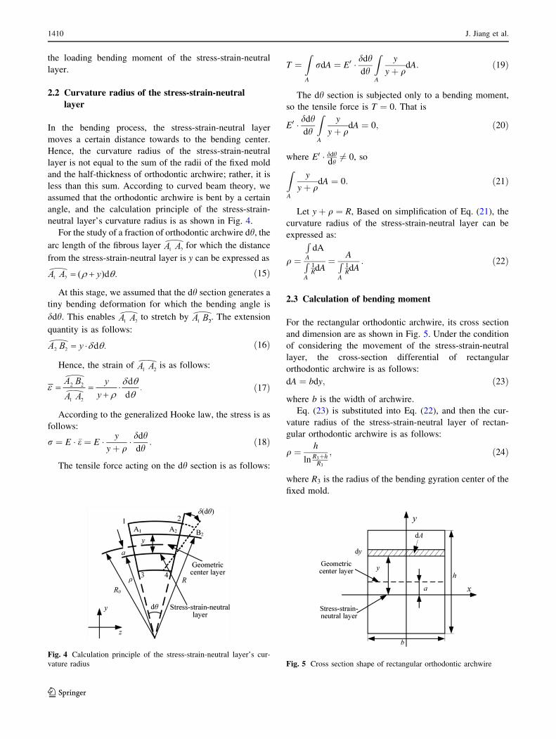
less than this sum. According to curved beam theory, we
assumed that the orthodontic archwire is bent by a certain
angle, and the calculation principle of the stress-strain-
neutral layer’s curvature radius is as shown in Fig. 4.
For the study of a fraction of orthodontic archwire dh, the
arc length of the fibrous layer for which the distance
from the stress-strain-neutral layer is y can be expressed as
ð15Þ
At this stage, we assumed that the dh section generates a
tiny bending deformation for which the bending angle is
ddh. This enables to stretch by . The extension
quantity is as follows:
ð16Þ
Hence, the strain of is as follows:
ð17Þ
According to the generalized Hooke law, the stress is as
follows:
r ¼ E � �e ¼ E � y
yþ q� ddh
dh: ð18Þ
The tensile force acting on the dh section is as follows:
T ¼ZA
rdA ¼ E0 � ddhdh
ZA
y
yþ qdA: ð19Þ
The dh section is subjected only to a bending moment,
so the tensile force is T ¼ 0. That is
E0 � ddhdh
ZA
y
yþ qdA ¼ 0; ð20Þ
where E0 � ddhdh
6¼ 0, so
ZA
y
yþ qdA ¼ 0: ð21Þ
Let yþ q ¼ R, Based on simplification of Eq. (21), the
curvature radius of the stress-strain-neutral layer can be
expressed as:
q ¼
RA
dA
RA
1RdA
¼ ARA
1RdA
: ð22Þ
2.3 Calculation of bending moment
For the rectangular orthodontic archwire, its cross section
and dimension are as shown in Fig. 5. Under the condition
of considering the movement of the stress-strain-neutral
layer, the cross-section differential of rectangular
orthodontic archwire is as follows:
dA ¼ bdy; ð23Þ
where b is the width of archwire.
Eq. (23) is substituted into Eq. (22), and then the cur-
vature radius of the stress-strain-neutral layer of rectan-
gular orthodontic archwire is as follows:
q ¼ h
ln R3þhR3
; ð24Þ
where R3 is the radius of the bending gyration center of the
fixed mold.
Fig. 4 Calculation principle of the stress-strain-neutral layer’s cur-
vature radius Fig. 5 Cross section shape of rectangular orthodontic archwire
1410 J. Jiang et al.
123

Eq. (23) is substituted into Eq. (10), and then the
unloading bending moment of rectangular orthodontic
archwire is as follows:
MU ¼ Ebh3 þ 12Eba2h
12
1
q� 1
q0
� �: ð25Þ
Similarly, Eq. (23) is substituted into Eq. (11), and then
the loading bending moment of rectangular orthodontic
archwire is as follows:
ML ¼ b
Z h2þa
�ðh2�aÞ
rðeÞ � ydy: ð26Þ
a can then be calculated as follows:
a ¼ R1 þ h=2 � q: ð27Þ
Under the condition of considering the real stress-strain
relationship, the calculation of the real strain is as follows:
e ¼ lnð1 þ �eÞ; ð28Þ
where �e is as follows:
�e ¼ y
q: ð29Þ
Therefore
y ¼ ðee � 1Þq; ð30Þdy ¼ qeede: ð31Þ
We assumed that the constitutive model of rectangular
orthodontic archwire is as follows:
r ¼ miei þ mi�1e
i�1 þ � � � þ m1e1 þ m0 ; i 2 N: ð32Þ
On the basis of the synthesis of Eqs. (26)-(32), the
loading bending moment of rectangular orthodontic arch-
wire is as follows:
ML ¼ q2b
Zlnð1þh=2þa
q Þlnð1þ�h=2þa
q ÞrðeÞ � ðe2e � eeÞde: ð33Þ
2.4 Calculation of springback angle and the formed
angle
On the basis of the synthesis of Eqs. (12), (14), (24), (25),
and (33), the calculation equations for the springback angle
and the formed angle of rectangular orthodontic archwire
are as follows:
hps ¼12MLq
Ebh3 þ 12Eba2hh; ð34Þ
h0p ¼ h� 12MLqEbh3 þ 12Eba2h
h: ð35Þ
Hence, when 0� h� hib; 0�Mi �ML, the calculation
equation for the total formed angle of rectangular
orthodontic archwire is as follows:
h0 ¼ Mi
6EI½2lþ 3n� � Mil
3EI: ð36Þ
When h� hib , he calculation equation for the total
formed angle of rectangular orthodontic archwire is as
follows:
h0 ¼ h� 12MLqEbh3 þ 12Eba2h
h� ML
6EI½2lþ 3n� �MLl
3EI
� �
þ K:
ð37Þ
where K is a correction coefficient from the elastic bending
stage to the plastic bending stage. In the bending process of
orthodontic archwire, it is continuous process from the
elastic bending stage to the plastic bending stage. When the
maximum bending moment is ML, and then the forming
angle and bending angle between the elastic bending stage
to the plastic bending stage is equal, therefore K is
determined.
3 Bending experiment for rectangular orthodonticarchwire
3.1 Bending springback experiment
3.1.1 Material performance parameter measurement
of rectangular orthodontic archwire
According to the wire material tensile testing method of the
national standard of the People’s Republic of China, tensile
tests of rectangular orthodontic archwire were conducted
using an Instron 5569 electronic universal material testing
machine at Harbin Institute of Technology. The Instron
5569 electronic universal material testing machine is as
shown in Fig. 6. The material of the rectangular
orthodontic archwire is stainless steel. Its dimensions are as
Fig. 6 Intron 5569 electronic universal material testing machine
Springback Mechanism Analysis and Experiments on Robotic Bending 1411
123

shown in Table 1. Tensile tests of rectangular orthodontic
archwire were conducted three times, and the testing elastic
modulus, yield strength and tensile strength of rectangular
orthodontic archwire are 191.070 GPa, 1.934 GPa and
2.409 GPa, respectively. Based on MATLAB, polynomial
fitting was conducted using the least squares method. The
test results and fitted stress-strain curve for the rectangular
orthodontic archwire are as shown in Fig. 7. As can been
seen from Fig. 6, the fitting effect of the stress-strain curve
is good. Its standard deviation is 6.0918. The fitted con-
stitutive model of rectangular orthodontic archwire is as
follows:
r ¼ �2:837 7e6e3 � 0:109 2e6e2 þ 0:045 4e6e1: ð38Þ
3.1.2 Springback experiment for rectangular orthodontic
archwire
Bending springback measurement experiments with rect-
angular orthodontic archwire were conducted using an
orthodontic archwire bending springback measuring
device designed in-house. The measuring equipment for
the formed angle of the orthodontic archwire adopted was
the OLYMPUS BX51M reflected/transmitted light dual-
use microscope, as shown in Fig. 8. The experimental
testing results, theoretical calculation results considering
the movement of the stress-strain-neutral layer, and the-
oretical calculation results without considering the
movement of the stress-strain-neutral layer for springback
of rectangular orthodontic archwire were compared and
analyzed. The relationship of the bending angle and the
formed angle of the rectangular orthodontic archwire is
shown in Fig. 9.
The theoretical calculation results considering the
movement of the stress-strain-neutral layer coincide better
with the experimental testing results than when movement
of the stress-strain-neutral layer was not considered. In
the initial bending stage, the main part of the total
deformation was elastic deformation. Therefore, the
springback angle occupied a large proportion of the
bending angle. With the increase of bending angle, plastic
deformation gradually became more obvious. The
springback angle increased with the increase of the
bending angle. However, its portion of the total bending
angle was gradually reduced. Finally, the bending angle
approximated a linear relationship with the springback
angle. The theoretical calculation results considering the
movement of the stress-strain-neutral layer were superior
to those in Ref. [29].
Table 1 Dimensions of rectangular orthodontic archwire
Length l/mm Cross-section
dimension S/(mm�mm)
Extensometer
gauge length l/mm
10.00 0.4490.54 25.00
Fig. 7 Testing and fitted stress-strain curve of rectangular orthodon-
tic archwire
Fig. 8 Measuring equipment for the formed angle of orthodontic
archwire
Fig. 9 Relationship of the bending angle and the formed angle of the
rectangular orthodontic archwire
1412 J. Jiang et al.
123
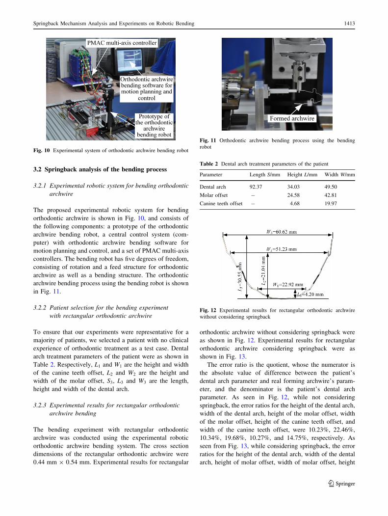
3.2 Springback analysis of the bending process
3.2.1 Experimental robotic system for bending orthodontic
archwire
The proposed experimental robotic system for bending
orthodontic archwire is shown in Fig. 10, and consists of
the following components: a prototype of the orthodontic
archwire bending robot, a central control system (com-
puter) with orthodontic archwire bending software for
motion planning and control, and a set of PMAC multi-axis
controllers. The bending robot has five degrees of freedom,
consisting of rotation and a feed structure for orthodontic
archwire as well as a bending structure. The orthodontic
archwire bending process using the bending robot is shown
in Fig. 11.
3.2.2 Patient selection for the bending experiment
with rectangular orthodontic archwire
To ensure that our experiments were representative for a
majority of patients, we selected a patient with no clinical
experience of orthodontic treatment as a test case. Dental
arch treatment parameters of the patient were as shown in
Table 2. Respectively, L1 and W1 are the height and width
of the canine teeth offset, L2 and W2 are the height and
width of the molar offset, S3, L3 and W3 are the length,
height and width of the dental arch.
3.2.3 Experimental results for rectangular orthodontic
archwire bending
The bending experiment with rectangular orthodontic
archwire was conducted using the experimental robotic
orthodontic archwire bending system. The cross section
dimensions of the rectangular orthodontic archwire were
0.44 mm 9 0.54 mm. Experimental results for rectangular
orthodontic archwire without considering springback were
as shown in Fig. 12. Experimental results for rectangular
orthodontic archwire considering springback were as
shown in Fig. 13.
The error ratio is the quotient, whose the numerator is
the absolute value of difference between the patient’s
dental arch parameter and real forming archwire’s param-
eter, and the denominator is the patient’s dental arch
parameter. As seen in Fig. 12, while not considering
springback, the error ratios for the height of the dental arch,
width of the dental arch, height of the molar offset, width
of the molar offset, height of the canine teeth offset, and
width of the canine teeth offset, were 10.23%, 22.46%,
10.34%, 19.68%, 10.27%, and 14.75%, respectively. As
seen from Fig. 13, while considering springback, the error
ratios for the height of the dental arch, width of the dental
arch, height of molar offset, width of molar offset, height
Fig. 10 Experimental system of orthodontic archwire bending robot
Fig. 11 Orthodontic archwire bending process using the bending
robot
Table 2 Dental arch treatment parameters of the patient
Parameter Length S/mm Height L/mm Width W/mm
Dental arch 92.37 34.03 49.50
Molar offset - 24.58 42.81
Canine teeth offset - 4.68 19.97
Fig. 12 Experimental results for rectangular orthodontic archwire
without considering springback
Springback Mechanism Analysis and Experiments on Robotic Bending 1413
123
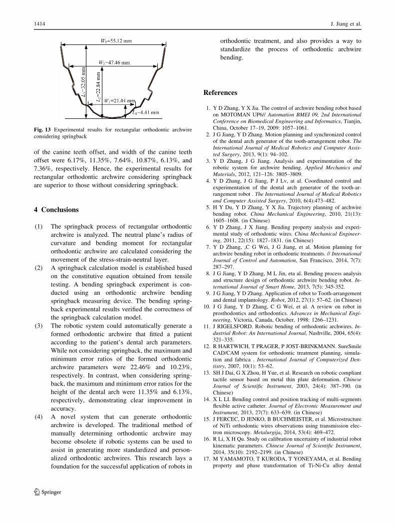
of the canine teeth offset, and width of the canine teeth
offset were 6.17%, 11.35%, 7.64%, 10.87%, 6.13%, and
7.36%, respectively. Hence, the experimental results for
rectangular orthodontic archwire considering springback
are superior to those without considering springback.
4 Conclusions
(1) The springback process of rectangular orthodontic
archwire is analyzed. The neutral plane’s radius of
curvature and bending moment for rectangular
orthodontic archwire are calculated considering the
movement of the stress-strain-neutral layer.
(2) A springback calculation model is established based
on the constitutive equation obtained from tensile
testing. A bending springback experiment is con-
ducted using an orthodontic archwire bending
springback measuring device. The bending spring-
back experimental results verified the correctness of
the springback calculation model.
(3) The robotic system could automatically generate a
formed orthodontic archwire that fitted a patient
according to the patient’s dental arch parameters.
While not considering springback, the maximum and
minimum error ratios of the formed orthodontic
archwire parameters were 22.46% and 10.23%,
respectively. In contrast, when considering spring-
back, the maximum and minimum error ratios for the
height of the dental arch were 11.35% and 6.13%,
respectively, demonstrating clear improvement in
accuracy.
(4) A novel system that can generate orthodontic
archwire is developed. The traditional method of
manually determining orthodontic archwire may
become obsolete if robotic systems can be used to
assist in generating more standardized and person-
alized orthodontic archwires. This research lays a
foundation for the successful application of robots in
orthodontic treatment, and also provides a way to
standardize the process of orthodontic archwire
bending.
References
1. Y D Zhang, Y X Jia. The control of archwire bending robot based
on MOTOMAN UP6// Automation BMEI 09, 2nd International
Conference on Biomedical Engineering and Informatics, Tianjin,
China, October 17–19, 2009: 1057–1061.
2. J G Jiang, Y D Zhang. Motion planning and synchronized control
of the dental arch generator of the tooth-arrangement robot. The
International Journal of Medical Robotics and Computer Assis-
ted Surgery, 2013, 9(1): 94–102.
3. Y D Zhang, J G Jiang. Analysis and experimentation of the
robotic system for archwire bending. Applied Mechanics and
Materials, 2012, 121–126: 3805–3809.
4. Y D Zhang, J G Jiang, P J Lv, at al. Coordinated control and
experimentation of the dental arch generator of the tooth-ar-
rangement robot . The International Journal of Medical Robotics
and Computer Assisted Surgery, 2010, 6(4):473–482.
5. H Y Du, Y D Zhang, Y X Jia. Trajectory planning of archwire
bending robot. China Mechanical Engineering, 2010, 21(13):
1605–1608. (in Chinese)
6. Y D Zhang, J X Jiang. Bending property analysis and experi-
mental study of orthodontic wires. China Mechanical Engineer-
ing, 2011, 22(15): 1827–1831. (in Chinese)
7. Y D Zhang, ,C G Wei, J G Jiang, et al. Motion planning for
archwire bending robot in orthodontic treatments. // International
Journal of Control and Automation, San Francisco, 2014, 7(7):
287–297.
8. J G Jiang, Y D Zhang, M L Jin, eta al. Bending process analysis
and structure design of orthodontic archwire bending robot. In-
ternational Journal of Smart Home, 2013, 7(5): 345-352.
9. J G Jiang, Y D Zhang. Application of robot to Tooth-arrangement
and dental implantology. Robot, 2012, 27(1): 57–62. (in Chinese)
10. J G Jiang, Y D Zhang, C G Wei, et al. A review on robot in
prosthodontics and orthodontics. Advances in Mechanical Engi-
neering, Victoria, Canada, October, 1998: 1266–1231.
11. J RIGELSFORD. Robotic bending of orthodontic archwires. In-
dustrial Robot: An International Journal, Nashville, 2004, 65(4):
321–335.
12. R HARTWICH, T PRAGER, P JOST-BRINKMANN. SureSmile
CAD/CAM system for orthodontic treatment planning, simula-
tion and fabrica . International Journal of Computerized Den-
tistry, 2007, 10(1): 53–62.
13. SH J Dai, G X Zhou, H Yue, et al. Research on robotic compliant
tactile sensor based on metal thin plate deformation. Chinese
Journal of Scientific Instrument, 2003, 24(4): 387–390. (in
Chinese)
14. X L LI. Bending control and position tracking of multi-segments
flexible active catheter. Journal of Electronic Measurement and
Instrument, 2013, 27(7): 633–639. (in Chinese)
15. J FERCEC, D JENKO, B BUCHMEISTER, et al. Microstructure
of NiTi orthodontic wires observations using transmission elec-
tron microscopy. Metalurgija, 2014, 53(4): 469–472.
16. R Li, X H Qu. Study on calibration uncertainty of industrial robot
kinematic parameters. Chinese Journal of Scientific Instrument,
2014, 35(10): 2192–2199. (in Chinese)
17. M YAMAMOTO, T KURODA, T YONEYAMA, et al. Bending
property and phase transformation of Ti-Ni-Cu alloy dental
Fig. 13 Experimental results for rectangular orthodontic archwire
considering springback
1414 J. Jiang et al.
123

castings for orthodontic application. Journal of Materials Sci-
ence: Materials in Medicine, 2002, 13(9): 855–859.
18. N A MAHMOUD, S TAHEREH, H MOHAMAD. Static and
cyclic load-deflection characteristics of NiTi orthodontic arch-
wires using modified bending tests. 5th ed. Journal of Materials
Engineering and Performance, 2009, 18(5–6): 793–796.
19. M P BRIAN, Z SPIROS, B T GERARD, et al. Structure, com-
position, and mechanical properties of Australian orthodontic
wires. Journal of Angle Orthodontist, 2009, 18(6): 97–101.
20. P SAMIRA, K LUDGER, R SUSANNE. Experimental analysis
of torque characteristics of orthodontic wires. Journal of Orofa-
cial Orthopedics, 2010, 71(5): 362–372.
21. I B NACEUR, A CHARFI, T BOURAOUI. Finite element
modeling of superelastic nickel-titanium orthodontic wires.
Journal of Biomechanics, 2014, 47(15): 3630–3638.
22. D R P H FREITAS, D S J M FERREIRA, W D S RUELLA.
Comparison of the load/deflection ratio between the heat-acti-
vated Ni-Ti orthodontic wires 0.014’’90.025’’ and
0.016’’90.022’’. Bioscience Journal, 2014, 30(4): 1259–1268.
23. Y Hou, Z S Li, W Yi, et al. Mechanics Unloading Analysis and
Experimentation of a New Type of Parallel Biomimetic Shoulder
Complex. Chinese Journal of Mechanical Engineering, 2016,
29(4): 649-658.
24. S Yao, L J Zhang, G P Wang, et al. Comparison of mechanical
properties and clinical significance of different orthodontic wires.
Journal of Modern Stomatology, 2000, 14(2): 92–94. (in Chinese)
25. Y Zhang, X Li, K Yang, et al. A comparative study of elemental
components and mechanical properties of beta-titanium alloy
wires. Beijing Journal of Stomatology, 2011, 19(2): 61–63. (in
Chinese)
26. X Li, K Yang, Y Zhang, et al. A comparison study of elemental
components, surface characteristics and mechanical properties
of beta-titanium alloy wires, nitinol wires and stainless steel
wires. Journal of Practical Stomatology, 2012, 28(1): 5–9. (in
Chinese)
27. T Wu, D Ying, L Yang, et al. Synthesized multi-station tribo-test
system for bio-tribological evaluation in vitro. Chinese Journal of
Mechanical Engineering, 2016, 29(4): 853-861.
28. M FREHNER. The neutral lines in buckle folds. Journal of
Structural Geology, 2011, 33(10): 1501–1508.
29. J B KRUGER, A N PALAZOTTO. An investigation of spring-
back in wire products. Journal of Engineering for Industry
Transactions of the ASME, 1972, 94(1): 329–335.
Jin-Gang Jiang, born in 1982, is currently an associate professor and
M. S candidate supervisor at Robotics & its Engineering Research
Center, Harbin University of Science and Technology, China. He
received his BS degree, MS degree and PhD degree from Harbin
University of Science and Technology, China, in 2005, 2008 and
2013, respectively. His main research interests include medical robot
and biomimetic robot. Tel: ?86-18846445528; E-mail:
Ying-Shuai Han, born in 1993, is currently a master candidate at
Robotics & its Engineering Research Center, Harbin University of
Science and Technology, China. E-mail: [email protected]
Yong-De Zhang, born in 1965, is currently a professor and a PhD
candidate supervisor at Robotics & its Engineering Research Center,
Harbin University of Science and Technology, China. His main
research interests include medical robot, education robot and
biomimetic robot. E-mail: [email protected]
Yan-Jv Liu, born in 1974, is currently a professor and M. S candidate
supervisor at Computing Center, Qiqihar University, China. His main
research interests include medical robot and image processing.
E-mail: [email protected]
Zhao Wang, born in 1990, is currently a master candidate at
Robotics & its Engineering Research Center, Harbin University of
Science and Technology, China. E-mail: [email protected]
Yi Liu, born in 1973, is currently a chief physician, associate
professor and master candidate supervisor at Peking University
Hospital of Stomatology, China. His main research interests include
Cone-beam CT and oral three-dimensional digital technology,
orthodontic treatment of occlusion function disorder and temporo-
mandibular joint disease E-mail: [email protected].
Springback Mechanism Analysis and Experiments on Robotic Bending 1415
123


