Download - Square Wave TIG 175 PRO
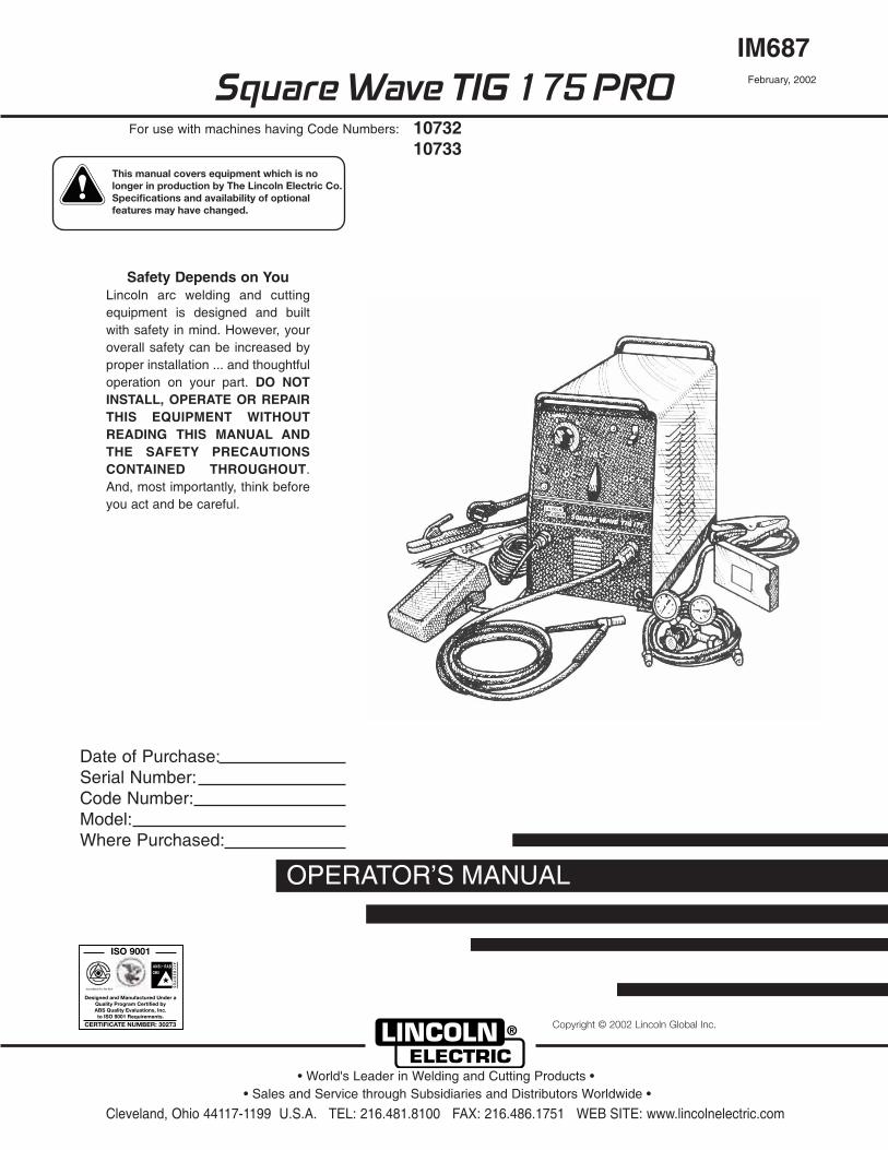
Square Wave TIG 175 PRO
OPERATOR’S MANUAL
IM687February, 2002
Safety Depends on YouLincoln arc welding and cuttingequipment is designed and builtwith safety in mind. However, youroverall safety can be increased byproper installation ... and thoughtfuloperation on your part. DO NOTINSTALL, OPERATE OR REPAIRTHIS EQUIPMENT WITHOUTREADING THIS MANUAL ANDTHE SAFETY PRECAUTIONSCONTAINED THROUGHOUT.And, most importantly, think beforeyou act and be careful.
For use with machines having Code Numbers: 1073210733
• Sales and Service through Subsidiaries and Distributors Worldwide •
Cleveland, Ohio 44117-1199 U.S.A. TEL: 216.481.8100 FAX: 216.486.1751 WEB SITE: www.lincolnelectric.com
• World's Leader in Welding and Cutting Products •
Date of Purchase:Serial Number:Code Number:Model:Where Purchased:
Copyright © 2002 Lincoln Global Inc.
RETURN TO MAIN INDEX
This manual covers equipment which is no longer in production by The Lincoln Electric Co. Speci�cations and availability of optional features may have changed.

FOR ENGINEpowered equipment.
1.a. Turn the engine off before troubleshooting and maintenancework unless the maintenance work requires it to be running.
____________________________________________________1.b.Operate engines in open, well-ventilated
areas or vent the engine exhaust fumes outdoors.
____________________________________________________1.c. Do not add the fuel near an open flame weld-
ing arc or when the engine is running. Stopthe engine and allow it to cool before refuel-ing to prevent spilled fuel from vaporizing oncontact with hot engine parts and igniting. Donot spill fuel when filling tank. If fuel is spilled,wipe it up and do not start engine until fumeshave been eliminated.
____________________________________________________1.d. Keep all equipment safety guards, covers and devices in posi-
tion and in good repair.Keep hands, hair, clothing and toolsaway from V-belts, gears, fans and all other moving partswhen starting, operating or repairing equipment.
____________________________________________________
1.e. In some cases it may be necessary to remove safetyguards to perform required maintenance. Removeguards only when necessary and replace them when themaintenance requiring their removal is complete.Always use the greatest care when working near movingparts.
___________________________________________________1.f. Do not put your hands near the engine fan.
Do not attempt to override the governor oridler by pushing on the throttle control rodswhile the engine is running.
___________________________________________________1.g. To prevent accidentally starting gasoline engines while
turning the engine or welding generator during maintenancework, disconnect the spark plug wires, distributor cap ormagneto wire as appropriate.
iSAFETYi
ARC WELDING CAN BE HAZARDOUS. PROTECT YOURSELF AND OTHERS FROM POSSIBLE SERIOUS INJURY OR DEATH.KEEP CHILDREN AWAY. PACEMAKER WEARERS SHOULD CONSULT WITH THEIR DOCTOR BEFORE OPERATING.
Read and understand the following safety highlights. For additional safety information, it is strongly recommended that youpurchase a copy of “Safety in Welding & Cutting - ANSI Standard Z49.1” from the American Welding Society, P.O. Box 351040,Miami, Florida 33135 or CSA Standard W117.2-1974. A Free copy of “Arc Welding Safety” booklet E205 is available from theLincoln Electric Company, 22801 St. Clair Avenue, Cleveland, Ohio 44117-1199.
BE SURE THAT ALL INSTALLATION, OPERATION, MAINTENANCE AND REPAIR PROCEDURES AREPERFORMED ONLY BY QUALIFIED INDIVIDUALS.
WARNING
Mar ‘95
ELECTRIC AND MAGNETIC FIELDSmay be dangerous
2.a. Electric current flowing through any conductor causes localized Electric and Magnetic Fields (EMF). Welding current creates EMF fields around welding cables and welding machines
2.b. EMF fields may interfere with some pacemakers, andwelders having a pacemaker should consult their physicianbefore welding.
2.c. Exposure to EMF fields in welding may have other healtheffects which are now not known.
2.d. All welders should use the following procedures in order tominimize exposure to EMF fields from the welding circuit:
2.d.1. Route the electrode and work cables together - Securethem with tape when possible.
2.d.2. Never coil the electrode lead around your body.
2.d.3. Do not place your body between the electrode andwork cables. If the electrode cable is on your right side, the work cable should also be on your right side.
2.d.4. Connect the work cable to the workpiece as close aspossible to the area being welded.
2.d.5. Do not work next to welding power source.
1.h. To avoid scalding, do not remove theradiator pressure cap when the engine ishot.
For Diesel Engines: Diesel engine exhaust andsome of its constituents are known to the Stateof California to cause cancer, birth defects, andother reproductive harm.
For Gasoline Engines: The engine exhaust fromthis product contains chemicals known to theState of California to cause cancer, birth defects,or other reproductive harm.
CALIFORNIA PROPOSITION 65 WARNINGS
SQUARE WAVE TIG 175 PRO
iiSAFETYii
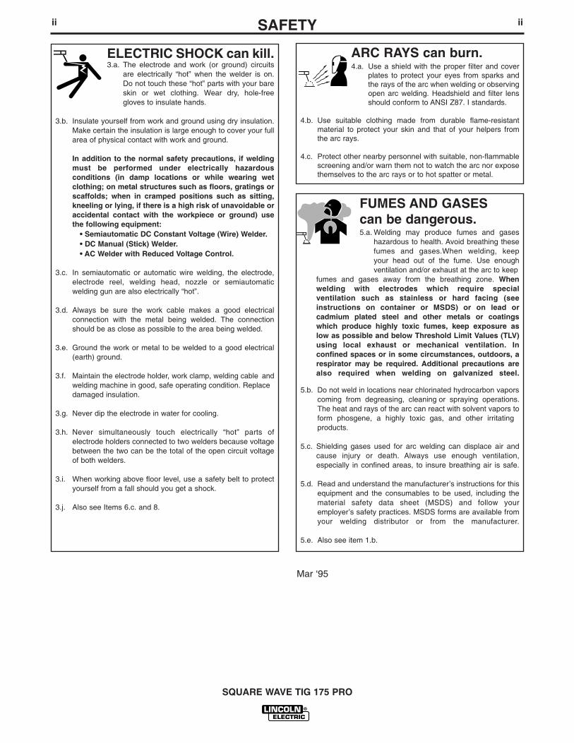
ARC RAYS can burn.4.a. Use a shield with the proper filter and cover
plates to protect your eyes from sparks andthe rays of the arc when welding or observingopen arc welding. Headshield and filter lensshould conform to ANSI Z87. I standards.
4.b. Use suitable clothing made from durable flame-resistantmaterial to protect your skin and that of your helpers fromthe arc rays.
4.c. Protect other nearby personnel with suitable, non-flammablescreening and/or warn them not to watch the arc nor exposethemselves to the arc rays or to hot spatter or metal.
ELECTRIC SHOCK can kill.3.a. The electrode and work (or ground) circuits
are electrically “hot” when the welder is on.Do not touch these “hot” parts with your bareskin or wet clothing. Wear dry, hole-freegloves to insulate hands.
3.b. Insulate yourself from work and ground using dry insulation.Make certain the insulation is large enough to cover your fullarea of physical contact with work and ground.
In addition to the normal safety precautions, if weldingmust be performed under electrically hazardousconditions (in damp locations or while wearing wetclothing; on metal structures such as floors, gratings orscaffolds; when in cramped positions such as sitting,kneeling or lying, if there is a high risk of unavoidable oraccidental contact with the workpiece or ground) usethe following equipment:
• Semiautomatic DC Constant Voltage (Wire) Welder.• DC Manual (Stick) Welder.• AC Welder with Reduced Voltage Control.
3.c. In semiautomatic or automatic wire welding, the electrode,electrode reel, welding head, nozzle or semiautomaticwelding gun are also electrically “hot”.
3.d. Always be sure the work cable makes a good electricalconnection with the metal being welded. The connectionshould be as close as possible to the area being welded.
3.e. Ground the work or metal to be welded to a good electrical(earth) ground.
3.f. Maintain the electrode holder, work clamp, welding cable andwelding machine in good, safe operating condition. Replacedamaged insulation.
3.g. Never dip the electrode in water for cooling.
3.h. Never simultaneously touch electrically “hot” parts ofelectrode holders connected to two welders because voltagebetween the two can be the total of the open circuit voltageof both welders.
3.i. When working above floor level, use a safety belt to protectyourself from a fall should you get a shock.
3.j. Also see Items 6.c. and 8.
FUMES AND GASEScan be dangerous.5.a. Welding may produce fumes and gases
hazardous to health. Avoid breathing thesefumes and gases.When welding, keepyour head out of the fume. Use enoughventilation and/or exhaust at the arc to keep
fumes and gases away from the breathing zone. Whenwelding with electrodes which require specialventilation such as stainless or hard facing (seeinstructions on container or MSDS) or on lead orcadmium plated steel and other metals or coatingswhich produce highly toxic fumes, keep exposure aslow as possible and below Threshold Limit Values (TLV)using local exhaust or mechanical ventilation. Inconfined spaces or in some circumstances, outdoors, arespirator may be required. Additional precautions arealso required when welding on galvanized steel.
5.b. Do not weld in locations near chlorinated hydrocarbon vaporscoming from degreasing, cleaning or spraying operations.The heat and rays of the arc can react with solvent vapors toform phosgene, a highly toxic gas, and other irritating products.
5.c. Shielding gases used for arc welding can displace air andcause injury or death. Always use enough ventilation,especially in confined areas, to insure breathing air is safe.
5.d. Read and understand the manufacturer’s instructions for thisequipment and the consumables to be used, including thematerial safety data sheet (MSDS) and follow youremployer’s safety practices. MSDS forms are available fromyour welding distributor or from the manufacturer.
5.e. Also see item 1.b.
Mar ‘95
SQUARE WAVE TIG 175 PRO

FOR ELECTRICALLYpowered equipment.
8.a. Turn off input power using the disconnectswitch at the fuse box before working onthe equipment.
8.b. Install equipment in accordance with the U.S. NationalElectrical Code, all local codes and the manufacturer’srecommendations.
8.c. Ground the equipment in accordance with the U.S. NationalElectrical Code and the manufacturer’s recommendations.
CYLINDER may explodeif damaged.7.a. Use only compressed gas cylinders
containing the correct shielding gas for theprocess used and properly operatingregulators designed for the gas and
pressure used. All hoses, fittings, etc. should be suitable forthe application and maintained in good condition.
7.b. Always keep cylinders in an upright position securelychained to an undercarriage or fixed support.
7.c. Cylinders should be located:• Away from areas where they may be struck or subjected tophysical damage.
• A safe distance from arc welding or cutting operations andany other source of heat, sparks, or flame.
7.d. Never allow the electrode, electrode holder or any otherelectrically “hot” parts to touch a cylinder.
7.e. Keep your head and face away from the cylinder valve outletwhen opening the cylinder valve.
7.f. Valve protection caps should always be in place and handtight except when the cylinder is in use or connected foruse.
7.g. Read and follow the instructions on compressed gascylinders, associated equipment, and CGA publication P-l,“Precautions for Safe Handling of Compressed Gases inCylinders,” available from the Compressed Gas Association1235 Jefferson Davis Highway, Arlington, VA 22202.
iiiSAFETYiii
Mar ‘95
WELDING SPARKS cancause fire or explosion.6.a. Remove fire hazards from the welding area.
If this is not possible, cover them to preventthe welding sparks from starting a fire.Remember that welding sparks and hot
materials from welding can easily go through small cracksand openings to adjacent areas. Avoid welding nearhydraulic lines. Have a fire extinguisher readily available.
6.b. Where compressed gases are to be used at the job site,special precautions should be used to prevent hazardoussituations. Refer to “Safety in Welding and Cutting” (ANSIStandard Z49.1) and the operating information for theequipment being used.
6.c. When not welding, make certain no part of the electrodecircuit is touching the work or ground. Accidental contact cancause overheating and create a fire hazard.
6.d. Do not heat, cut or weld tanks, drums or containers until theproper steps have been taken to insure that such procedureswill not cause flammable or toxic vapors from substancesinside. They can cause an explosion even though they havebeen “cleaned”. For information, purchase “RecommendedSafe Practices for the Preparation for Welding and Cutting ofContainers and Piping That Have Held HazardousSubstances”, AWS F4.1 from the American Welding Society(see address above).
6.e. Vent hollow castings or containers before heating, cutting orwelding. They may explode.
6.f. Sparks and spatter are thrown from the welding arc. Wear oilfree protective garments such as leather gloves, heavy shirt,cuffless trousers, high shoes and a cap over your hair. Wearear plugs when welding out of position or in confined places.Always wear safety glasses with side shields when in awelding area.
6.g. Connect the work cable to the work as close to the weldingarea as practical. Work cables connected to the buildingframework or other locations away from the welding areaincrease the possibility of the welding current passingthrough lifting chains, crane cables or other alternate circuits.This can create fire hazards or overheat lifting chains orcables until they fail.
6.h. Also see item 1.c.
SQUARE WAVE TIG 175 PRO

ivSAFETYiv
PRÉCAUTIONS DE SÛRETÉPour votre propre protection lire et observer toutes les instructionset les précautions de sûreté specifiques qui parraissent dans cemanuel aussi bien que les précautions de sûreté générales suiv-antes:
Sûreté Pour Soudage A L’Arc1. Protegez-vous contre la secousse électrique:
a. Les circuits à l’électrode et à la piéce sont sous tensionquand la machine à souder est en marche. Eviter toujourstout contact entre les parties sous tension et la peau nueou les vétements mouillés. Porter des gants secs et sanstrous pour isoler les mains.
b. Faire trés attention de bien s’isoler de la masse quand onsoude dans des endroits humides, ou sur un plancher met-allique ou des grilles metalliques, principalement dans les positions assis ou couché pour lesquelles une grandepartie du corps peut être en contact avec la masse.
c. Maintenir le porte-électrode, la pince de masse, le câble desoudage et la machine à souder en bon et sûr état defonc-tionnement.
d.Ne jamais plonger le porte-électrode dans l’eau pour lerefroidir.
e. Ne jamais toucher simultanément les parties sous tensiondes porte-électrodes connectés à deux machines à soud-er parce que la tension entre les deux pinces peut être letotal de la tension à vide des deux machines.
f. Si on utilise la machine à souder comme une source decourant pour soudage semi-automatique, ces precautionspour le porte-électrode s’applicuent aussi au pistolet desoudage.
2. Dans le cas de travail au dessus du niveau du sol, se protégercontre les chutes dans le cas ou on recoit un choc. Ne jamaisenrouler le câble-électrode autour de n’importe quelle partiedu corps.
3. Un coup d’arc peut être plus sévère qu’un coup de soliel,donc:
a. Utiliser un bon masque avec un verre filtrant appropriéainsi qu’un verre blanc afin de se protéger les yeux du ray-onnement de l’arc et des projections quand on soude ouquand on regarde l’arc.
b. Porter des vêtements convenables afin de protéger lapeau de soudeur et des aides contre le rayonnement del‘arc.
c. Protéger l’autre personnel travaillant à proximité ausoudage à l’aide d’écrans appropriés et non-inflammables.
4. Des gouttes de laitier en fusion sont émises de l’arc desoudage. Se protéger avec des vêtements de protection libresde l’huile, tels que les gants en cuir, chemise épaisse, pan-talons sans revers, et chaussures montantes.
5. Toujours porter des lunettes de sécurité dans la zone desoudage. Utiliser des lunettes avec écrans lateraux dans les
zones où l’on pique le laitier.
6. Eloigner les matériaux inflammables ou les recouvrir afin deprévenir tout risque d’incendie dû aux étincelles.
7. Quand on ne soude pas, poser la pince à une endroit isolé dela masse. Un court-circuit accidental peut provoquer unéchauffement et un risque d’incendie.
8. S’assurer que la masse est connectée le plus prés possible dela zone de travail qu’il est pratique de le faire. Si on place lamasse sur la charpente de la construction ou d’autres endroitséloignés de la zone de travail, on augmente le risque de voirpasser le courant de soudage par les chaines de levage,câbles de grue, ou autres circuits. Cela peut provoquer desrisques d’incendie ou d’echauffement des chaines et descâbles jusqu’à ce qu’ils se rompent.
9. Assurer une ventilation suffisante dans la zone de soudage.Ceci est particuliérement important pour le soudage de tôlesgalvanisées plombées, ou cadmiées ou tout autre métal quiproduit des fumeés toxiques.
10. Ne pas souder en présence de vapeurs de chlore provenantd’opérations de dégraissage, nettoyage ou pistolage. Lachaleur ou les rayons de l’arc peuvent réagir avec les vapeursdu solvant pour produire du phosgéne (gas fortement toxique)ou autres produits irritants.
11. Pour obtenir de plus amples renseignements sur la sûreté, voirle code “Code for safety in welding and cutting” CSA StandardW 117.2-1974.
PRÉCAUTIONS DE SÛRETÉ POURLES MACHINES À SOUDER ÀTRANSFORMATEUR ET ÀREDRESSEUR
1. Relier à la terre le chassis du poste conformement au code del’électricité et aux recommendations du fabricant. Le dispositifde montage ou la piece à souder doit être branché à unebonne mise à la terre.
2. Autant que possible, I’installation et l’entretien du poste seronteffectués par un électricien qualifié.
3. Avant de faires des travaux à l’interieur de poste, la debranch-er à l’interrupteur à la boite de fusibles.
4. Garder tous les couvercles et dispositifs de sûreté à leurplace.
Mar. ‘93
SQUARE WAVE TIG 175 PRO

Thank You for selecting a QUALITY product by Lincoln Electric. We want youto take pride in operating this Lincoln Electric Company product •••as much pride as we have in bringing this product to you!
Read this Operators Manual completely before attempting to use this equipment. Save this manual and keep ithandy for quick reference. Pay particular attention to the safety instructions we have provided for your protection.The level of seriousness to be applied to each is explained below:
WARNINGThis statement appears where the information must be followed exactly to avoid serious personal injury orloss of life.
This statement appears where the information must be followed to avoid minor personal injury or damage tothis equipment.
CAUTION
Please Examine Carton and Equipment For Damage ImmediatelyWhen this equipment is shipped, title passes to the purchaser upon receipt by the carrier. Consequently, Claimsfor material damaged in shipment must be made by the purchaser against the transportation company at thetime the shipment is received.
Please record your equipment identification information below for future reference. This information can be foundon your machine nameplate.
Model Name & Number _____________________________________
Code & Serial Number _____________________________________
Date of Purchase _____________________________________
Whenever you request replacement parts for or information on this equipment always supply the information youhave recorded above.
vv

TABLE OF CONTENTSPage
Installation ..........................................................................................................Section ATechnical Specifications...............................................................................................A-1Saftey Precautions.. ............................................................................................................................................... .A-2
Select Suitable Location........................................................................................A-2Grinding .................................................................................................................A-2Stacking.................................................................................................................A-2Lifting .....................................................................................................................A-2Tilting .....................................................................................................................A-2Enviromental Rating ..............................................................................................A-2
Machine Grounding and High FREQUENCY INTERFERANCE PROTECTION ...................A-2,A-3Input Connections ........................................................................................................A-3Input Reconnect Procedure .........................................................................................A-3Output Connections .....................................................................................................A-4
Connections For Tig (GTAW) Welding............................................................A-4Tig Torch Connections ....................................................................................A-4Work Cable Connections ................................................................................A-4Shielding Gas Connection ..............................................................................A-4Remote Control Connection............................................................................A-5Connections For Stick (SMAW) Welding .......................................................A-5Stick Electrode Cable and Work Cable Connection .......................................A-5
OPERATION .........................................................................................................................................................Section B-1Saftey Precautions.......................................................................................................B-1Product Description......................................................................................................B-1
Included Equipment...............................................................................................B-1 GTAW (Tig Welding): ......................................................................................B-1SMAW (Stick Welding): ...................................................................................B-1Installation and Startup: ..................................................................................B-1
Welding Capability .................................................................................................B-1Controls and Settings ..........................................................................B-2 THRU B-3Operating Steps.....................................................................................................B-3
Welding in Tig Mode .......................................................................................B-3Remote Control Operation ..............................................................................B-3Benefits of the square Wave Operation..........................................................B-3
Welding in Stick Mode ..........................................................................................B-4
Accessories ............................................................................................................................................... .......Section COptional Equipment .....................................................................................................C-1
Maintenance......................................................................................................................................................Section DSaftey Precautions.......................................................................................................D-1Routine and Periodic Maintenance..............................................................................D-1
Troubleshooting.............................................................................................................................................Section ESaftey Precautions.......................................................................................................E-1How To Use TroubleShooting Guide............................................................................E-1Troubleshooting.................................................................................................E-2 to E-7
Diagrams ..............................................................................................................................................................Section FWiring Diagram 208/230 V Model...................................................................................................................F-1Wiring Diagram 460/575 V Model...................................................................................................................F-2
Parts List................................................................................................................................................P373,P210,P66
vivi
A-1INSTALLATION
SQUARE WAVE TIG 175 PRO
A-1
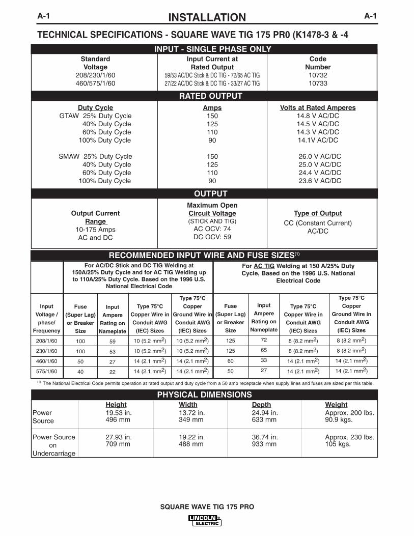
TECHNICAL SPECIFICATIONS - SQUARE WAVE TIG 175 PR0 (K1478-3 & -4
For AC/DC Stick and DC TIG Welding at150A/25% Duty Cycle and for AC TIG Welding upto 110A/25% Duty Cycle. Based on the 1996 U.S.
National Electrical Code
For AC TIG Welding at 150 A/25% DutyCycle, Based on the 1996 U.S. National
Electrical Code
CodeNumber1073210733
Volts at Rated Amperes14.8 V AC/DC14.5 V AC/DC14.3 V AC/DC14.1V AC/DC
26.0 V AC/DC25.0 V AC/DC24.4 V AC/DC23.6 V AC/DC
Type of OutputCC (Constant Current)
AC/DC
Input Current atRated Output
59/53 AC/DC Stick & DC TIG - 72/65 AC TIG27/22 AC/DC Stick & DC TIG - 33/27 AC TIG
Amps15012511090
15012511090
Maximum Open Circuit Voltage(STICK AND TIG)
AC OCV: 74DC OCV: 59
StandardVoltage
208/230/1/60460/575/1/60
Duty CycleGTAW 25% Duty Cycle
40% Duty Cycle60% Duty Cycle
100% Duty Cycle
SMAW 25% Duty Cycle40% Duty Cycle60% Duty Cycle
100% Duty Cycle
Output Current Range
10-175 AmpsAC and DC
INPUT - SINGLE PHASE ONLY
RATED OUTPUT
OUTPUT
RECOMMENDED INPUT WIRE AND FUSE SIZES(1)
Input
Voltage /
phase/
Frequency
208/1/60
230/1/60
460/1/60
575/1/60
Input
Ampere
Rating on
Nameplate
59
53
27
22
Type 75°C
Copper
Ground Wire in
Conduit AWG
(IEC) Sizes
10 (5.2 mm2)
10 (5.2 mm2)
14 (2.1 mm2)
14 (2.1 mm2)
Fuse
(Super Lag)
or Breaker
Size
100
100
50
40
Type 75°C
Copper Wire in
Conduit AWG
(IEC) Sizes
10 (5.2 mm2)
10 (5.2 mm2)
14 (2.1 mm2)
14 (2.1 mm2)
Type 75°C
Copper
Ground Wire in
Conduit AWG
(IEC) Sizes
8 (8.2 mm2)
8 (8.2 mm2)
14 (2.1 mm2)
14 (2.1 mm2)
Type 75°C
Copper Wire in
Conduit AWG
(IEC) Sizes
8 (8.2 mm2)
8 (8.2 mm2)
14 (2.1 mm2)
14 (2.1 mm2)
Input
Ampere
Rating on
Nameplate
72
65
33
27
Height Width Depth WeightPower 19.53 in. 13.72 in. 24.94 in. Approx. 200 lbs.Source 496 mm 349 mm 633 mm 90.9 kgs.
Power Source 27.93 in. 19.22 in. 36.74 in. Approx. 230 lbs.on 709 mm 488 mm 933 mm 105 kgs.
Undercarriage
PHYSICAL DIMENSIONS
Fuse
(Super Lag)
or Breaker
Size
125
125
60
50
(1) The National Electrical Code permits operation at rated output and duty cycle from a 50 amp receptacle when supply lines and fuses are sized per this table.

A-2INSTALLATION
SQUARE WAVE TIG 175 PRO
A-2
ELECTRIC SHOCK can kill.• Only qualified personnel should
perform this installation.
• Turn the input power OFF at the disconnect switch or fuse box before working on this equipment.
• Do not touch electrically hot parts.
• Always connect the SQUARE WAVE TIG 175 PRO toa power supply grounded per the NationalElectrical Code and any local codes.
WARNING
SAFETY PRECAUTIONS
SELECT SUITABLE LOCATIONPlace the welder where clean cooling air can freely cir-culate in through the rear louvers and out through thefront and side louvers. Dirt, dust or any foreign mater-ial that can be drawn into the welder should be kept ata minimum. Failure to observe these precautions canresult in excessive operating temperatures and nui-sance shut-downs.
GRINDINGDo not direct grinding particles towards the welder. Anabundance of conductive material can cause mainte-nance problems.
STACKINGSquare Wave TIG 175 PRO’s cannot be stacked.
LIFTING AND MOVINGThe Square Wave TIG 175 PRO should be lifted by twoor more people or with a hoist. (It weighs approximate-ly 200 lbs./90.9 kg.) Its lifting handles are designed tomake lifting more convenient. An optional undercarriageis available to easily move the unit. Refer to theAccessories section of this manual.
TILTINGEach machine must be placed on a secure, level sur-face, either directly or on a recommended undercar-riage. The machine may topple over if this procedureis not followed.
ENVIRONMENTAL RATINGThe SQUARE WAVE TIG 175 PRO power source carries anIP21 environmental rating. It may be used in normal industri-al and commercial environments. Avoid using it in environ-ments which have falling water such as rain. Read and fol-low “Electric Shock Warnings” in the Safety section if weld-ing must be performed under electrically hazardous condi-tions such as welding in wet areas or on or in the workpiece.
MACHINE GROUNDING AND HIGH FRE-QUENCY INTERFERENCE PROTECTION
The welder must be grounded. See your local and nationalelectrical codes for proper grounding methods.
The high frequency generator, being similar to a radiotransmitter, can be blamed for radio, TV and electronicequipment interference problems. These problemsmay be the result of radiated interference. Propergrounding methods can reduce or eliminate radiatedinterference.
Radiated interference can develop in the following fourways:
1. Direct interference radiated from the welder.
2. Direct interference radiated from the welding leads.
3. Direct interference radiated from feedback into the power lines.
4. Interference from re-radiation of “pickup” by ungrounded metallic objects.
Keeping these contributing factors in mind, installingequipment per the following instructions should mini-mize problems.
1. Keep the welder power supply lines as short as pos-sible and enclose as much of them as possible inrigid metallic conduit or equivalent shielding for adistance of 50 feet (15.2m). There should be goodelectrical contact between this conduit and thewelder case ground. Both ends of the conduitshould be connected to a driven ground and theentire length should be continuous.
2. Keep the work and electrode leads as short as pos-sible and as close together as possible. Lengthsshould not exceed 25 ft (7.6m). Tape the leadstogether when practical.
3. Be sure the torch and work cable rubber coveringsare free of cuts and cracks that allow high frequen-cy leakage.
4. Keep the torch in good repair and all connectionstight to reduce high frequency leakage.
5. The work piece must be connected to an earthground close to the work clamp, using one of thefollowing methods:
Read entire installation section before startinginstallation.

INPUT RECONNECT PROCEDURE
On multiple input voltage welders, be sure the machineis connected per the following instructions for the volt-age being supplied to the welder.
Failure to follow these instructions can cause immedi-ate failure of components within the welder.___________________________________________
Multiple voltage models are shipped connected for thehighest voltage. To change this connection refer to thefollowing instructions.
For the lowestrated voltage connection (Refer to figure A.1):
1. Remove the sheet metal cover.
2. Disconnect lead H3 from the power switch and insu-late with the insulation from the H2 lead.
3. Connect lead H2 to the power switch where H3 wasconnected.
4. Tighten connections.
5. Replace sheet metal cover and all screws
For the highest rated voltage connection (Refer to figure A.1):The machine is normally shipped connected for thehighest rated voltage, however verify the following:
1. Remove the sheet metal cover.
2. Disconnect lead H2 from the power switch and insu-late with the insulation from the H3 lead.
3. Connect lead H3 to the line switch where H2 wasconnected.
4. Tighten connections.
5. Replace sheet metal cover and all screws.
A-3INSTALLATION
SQUARE WAVE TIG 175 PRO
A-3
a) A metal underground water pipe in direct contactwith the earth for ten feet or more.
b) A 3/4” (19mm) galvanized pipe or a 5/8” (16mm)solid galvanized iron, steel or copper rod drivenat least eight feet into the ground.
The ground should be securely made and the ground-ing cable should be as short as possible using cable ofthe same size as the work cable, or larger. Groundingto the building frame electrical conduit or a long pipesystem can result in re-radiation, effectively makingthese members radiating antennas.
6. Keep cover and all screws securely in place.7. Electrical conductors within 50 ft (15.2m) of the
welder should be enclosed in grounded rigid metal-lic conduit or equivalent shielding, wherever possi-ble. Flexible metallic conduit is generally not suit-able.
8. When the welder is enclosed in a metal building, themetal building should be connected to several goodearth driven electrical grounds (as in 5 (b) above)around the periphery of the building.
Failure to observe these recommended installationprocedures can cause radio or TV and electronicequipment interference problems and result in unsatis-factory welding performance resulting from lost highfrequency power.
INPUT CONNECTIONS
Be sure the voltage, phase, and frequency of the inputpower is as specified on the rating plate, located on therear of the machine.
208/230 volt models have a NEMA 6-50P plugattached to the input power cord and a NEMA 6-50Rreceptacle is included. Other voltage models have aninput power cord but no plug or receptacle.
Have a qualified electrician provide input power supplyto the receptacle or cord in accordance with all localand national electrical codes. Use a single phase lineor one phase of a two or three phase line. Choose aninput and grounding wire size according to local ornational codes. Refer to the Technical Specificationspage at the beginning of this section. Fuse the inputcircuit with the recommended super lag fuses or delaytype1 circuit breakers. Using fuses or circuit breakerssmaller than recommended may result in “nuisance”shut-offs from welder inrush currents even if not weld-ing at high currents.
CAUTION
1Also called “inverse time” or “thermal/magnetic” circuit breakers; circuitbreakers which have a delay in tripping action that decreases as the magni-tude of the current increases.
WARNINGELECTRIC SHOCK can kill.
• Turn the input power OFF at thedisconnect switch or fuse boxbefore working on thisequipment.
A-4INSTALLATION
SQUARE WAVE TIG 175 PRO
A-4
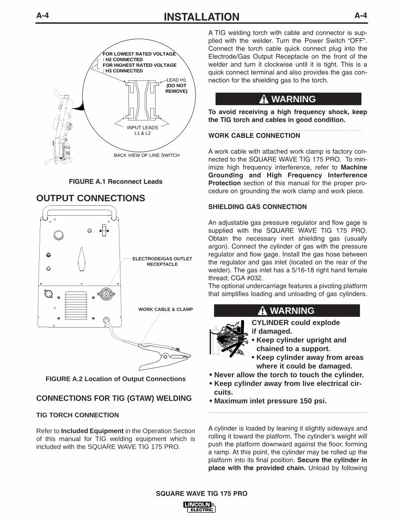
A TIG welding torch with cable and connector is sup-plied with the welder. Turn the Power Switch “OFF”.Connect the torch cable quick connect plug into theElectrode/Gas Output Receptacle on the front of thewelder and turn it clockwise until it is tight. This is aquick connect terminal and also provides the gas con-nection for the shielding gas to the torch.
To avoid receiving a high frequency shock, keepthe TIG torch and cables in good condition.__________________________________________WORK CABLE CONNECTION
A work cable with attached work clamp is factory con-nected to the SQUARE WAVE TIG 175 PRO. To min-imize high frequency interference, refer to MachineGrounding and High Frequency InterferenceProtection section of this manual for the proper pro-cedure on grounding the work clamp and work piece.
SHIELDING GAS CONNECTION
An adjustable gas pressure regulator and flow gage issupplied with the SQUARE WAVE TIG 175 PRO.Obtain the necessary inert shielding gas (usuallyargon). Connect the cylinder of gas with the pressureregulator and flow gage. Install the gas hose betweenthe regulator and gas inlet (located on the rear of thewelder). The gas inlet has a 5/16-18 right hand femalethread; CGA #032. The optional undercarriage features a pivoting platformthat simplifies loading and unloading of gas cylinders.
A cylinder is loaded by leaning it slightly sideways androlling it toward the platform. The cylinder’s weight willpush the platform downward against the floor, forminga ramp. At this point, the cylinder may be rolled up theplatform into its final position. Secure the cylinder inplace with the provided chain. Unload by following
FIGURE A.1 Reconnect Leads
INPUT LEADS L1 & L2
LEAD H1(DO NOT REMOVE)
FOR LOWEST RATED VOLTAGE: H2 CONNECTEDFOR HIGHEST RATED VOLTAGE: H3 CONNECTED
BACK VIEW OF LINE SWITCH
CYLINDER could explode if damaged.• Keep cylinder upright and
chained to a support.• Keep cylinder away from areas
where it could be damaged.• Never allow the torch to touch the cylinder.• Keep cylinder away from live electrical cir-
cuits.• Maximum inlet pressure 150 psi.___________________________________________
WARNING
CONNECTIONS FOR TIG (GTAW) WELDING
TIG TORCH CONNECTION
Refer to Included Equipment in the Operation Sectionof this manual for TIG welding equipment which isincluded with the SQUARE WAVE TIG 175 PRO.
WARNING
OUTPUT CONNECTIONS
FIGURE A.2 Location of Output Connections
ELECTRODE/GAS OUTLETRECEPTACLE
WORK CABLE & CLAMP

A-5INSTALLATION
SQUARE WAVE TIG 175 PRO
A-5
these steps in reverse.REMOTE CONTROL CONNECTION
A remote control receptacle is provided on the casefront of the welder for connecting a remote control toto the machine. A Foot Amptroltm, foot activated remotecontrol, is included with the SQUARE WAVE TIG 175PRO. Refer to the Optional Accessories section of thismanual for other available remote controls.
CONNECTIONS FOR STICK (SMAW)WELDING
STICK ELECTRODE CABLE AND WORK CABLECONNECTION
Refer to Included Equipment in the Operation Sectionof this manual for STICK welding equipment which isincluded with the SQUARE WAVE TIG 175 PRO.
An electrode holder with cable is supplied with theSQUARE WAVE TIG 175 PRO. Turn the PowerSwitch “OFF”. Connect the cable quick connect pluginto the Electrode/Gas Output Receptacle and turn itclockwise until it is tight. The work cable and workclamp are factory connected.
B-1OPERATIONB-1
PRODUCT DESCRIPTION
The SQUARE WAVE TIG 175 PRO is a constant cur-rent, single range AC/DC TIG (GTAW) arc weldingpower source with built-in arc starter / stabilizer. It alsohas stick welding (SMAW) capability.
The SQUARE WAVE TIG 175 PRO is recommendedfor the TIG (GTAW) and stick (SMAW) weldingprocesses within its output capacity of 10 to 175 amps,on both AC and DC polarity.
INCLUDED EQUIPMENT
For GTAW (TIG Welding):• TIG torch, factory assembled with:
• 12.5 ft (3.8m) one-piece cable• 3/32” Collet body• 3/32” Collet• Short backcap
Not assembled:• 3/32” x 7” 2% Thoriated Tungsten Electrode• Long backcap• 1/2” Diameter Alumina gas cup
• Adjustable argon gas pressure regulator and flowgage
• Gas hose• Foot Amptroltm remote current control with 15ft
(4.6m) cable
For SMAW (Stick Welding):• Electrode holder with cable and quick connect plug• Electrode sample pack.
For Installation and startup:• “How To” VHS Videotape• Work Cable and Clamp• Input Cord• Input plug and receptacle (208/230 volt models only)
WELDING CAPABILITY
The SQUARE WAVE TIG 175 PRO is rated at 150amps, 15 volts, at 25% duty cycle on a ten minutebasis. It is capable of higher duty cycles at lower out-put currents. It is capable of 175 amps, 27 volts at alower duty cycle. If the duty cycle is exceeded, a ther-mal protector will shut off the output until the machine
cools.
SQUARE WAVE TIG 175 PRO
ELECTRIC SHOCKcan kill.• Do not touch electrically live parts
or electrode with skin or wet cloth-ing.
• Insulate yourself from work andground.
• Always wear dry insulating gloves.• Read and follow “Electric Shock
Warnings” in the Safety section if weld-ing must be performed under electrical-ly hazardous conditions such as weld-ing in wet areas or on or in the work-piece.
FUMES AND GASEScan be dangerous.• Keep your head out of fumes.• Use ventilation or exhaust to
remove fumes from breathingzone.
WELDING SPARKScan cause fire orexplosion• Keep flammable material away.• Do not weld on containers that
have held combustibles.
ARC RAYScan burn.
• Wear eye, ear and bodyprotection.
SAFETY PRECAUTIONS
Read and understand this entire section before operat-ing the machine.
Observe additional Safety Guidelines detailed inthe beginning of this manual.
WARNING

B-2OPERATIONB-2
1. POWER SWITCH & LIGHT - Turns power on oroff to the welder. When switched “ON”, thecooling fan runs and the light will illuminate indicat-ing that the power is on.
2. TIG/STICK SWITCH - Selects the mode of output,either TIG (GTAW) or Stick (SMAW). Refer toWelding in TIG Mode and Welding in Stick Modelater in this chapter for information on how themachine functions in each of these modes.
3. POLARITY SWITCH - Allows you to select betweenwelding in AC , DC - , or DC+ polar-ity. In DC + polarity the electrode is positive and thework clamp is negative. Use DC + for most stickwelding. In DC - the electrode is negative and thework clamp is positive. Use DC - for TIG weldingstainless steel and mild steel. AC polarity is recom-mended for TIG welding aluminum.
Do not switch the polarity switch whilewelding or damage may result to themachine.
------------------------------------------------------------------------
4. CURRENT CONTROL - This control is active inboth TIG and Stick modes. In Stick mode the cur-rent control sets the welding current. In TIG modethis control sets the maximum current. The Amptroltm
will adjust the welding current from the machine min-imum to this maximum setting.
5. OVER TEMPERATURE LIGHT - If the welderoverheats due to blocked air flow, high ambient airtemperature, or exceeded duty cycle, an internalthermostat will open disabling the welding outputand this yellow light will illuminate. The cooling fanswill continue to run to cool the unit during this time.The light will go out when the unit cools and thethermostat resets.
SQUARE WAVE TIG 175 PRO
CONTROLS AND SETTINGS
All operator controls and adjustments are located on the front of the SQUARE WAVE TIG 175 PRO. Refer toFigure B.1 and corresponding explanations.
FIGURE B.1 - CONTROL PANEL
1. POWER SWITCH & LIGHT2. TIG/STICK SWITCH3. POLARITY SWITCH4. CURRENT CONTROL5. OVER TEMPERATURE LIGHT6. REMOTE CONTROL CONNECTOR7. ELECTRODE/ GAS OUTPUT RECEPTACLE8. WORK CABLE & CLAMP
CAUTION
1
2 3
4
5
67
8
B-3OPERATIONB-3
6. REMOTE CONTROL CONNECTOR - This connectorprovides connection for a remote control. See RemoteControl Operation in this section of the manual.
7. ELECTRODE/GAS OUTPUT RECEPTACLE - Thisquick connect receptacle provides electrical connec-tion to the electrode holder and cable for Stick weld-ing and a combined electrical and gas connectionfor the TIG torch when TIG welding.
8. WORK CABLE - This work cable is factory con-nected to the welder and is connected to the workpiece to complete the welding circuit. Refer toMachine Grounding and High FrequencyInterference Protection in the Installation sectionof this manual for the proper procedure on ground-ing the work clamp and work piece to minimize highfrequency interference.
OPERATING STEPS
WELDING IN TIG MODE
1. Connect the TIG torch and cable quick connect plugto the Electrode/Gas output receptacle. This recep-tacle also contains an integral gas connection for thetorch. Connect the work clamp to the work piece.
2. Set the TIG/STICK switch to “TIG”.
3. Set the Polarity Switch to DC- for welding steel orstainless steel; or to AC for welding aluminum.
4. Connect the Foot Amptrol to the Remote Control Connector.
5. Turn on the cylinder gas valve and adjust the flowregulator to obtain desired flow.
6. Turn the power switch to “ON”. NOTE: There will bea 15 second gas flow when the power is turned on.
7. Set the Current Control on the control panel to themaximum desired amps.
8. Depress the Foot Amptrol to energize the torch andestablish an an arc with the work piece.
NOTE: When the TIG/STICK switch is set to “TIG”,depressing the remote control will start a 0.5 second gaspre-flow before energizing the TIG torch. When the remotecontrol is released the TIG torch is de-energized and gasflow will continue for a 15 second post flow. When thepolarity switch is set to DC, the TIG Arc Starter will turn onand off automatically to start and stabilize the arc. In AC theTIG Arc Starter will turn on with the output and remain oncontinuously until the remote control is released.
REMOTE CONTROL OPERATION
A Foot Amptrol™ is included with the SQUARE WAVETIG 175 PRO for remote current control while TIGwelding. An optional Hand Amptrol may also be used.An optional Arc Start Switch may be used to start andstop the welding if no remote control of the current isdesired. Refer to the Accessories section of this man-ual.
Both the Hand and Foot Amptrol work in a similar man-ner. For simplicity, the following explanation will referonly to “Amptrols”, meaning both Foot and Hand mod-els. The term “minimum” refers to a foot pedal in the“up” position, as it would be with no foot pressure, or aHand Amptrol in the relaxed position, with no thumbpressure. “Maximum” refers to a fully depressed FootAmptrol, or a fully extended Hand Amptrol.
When the welder is in TIG mode activating the Amptrolenergizes the electrode terminal and varies the outputwelding current from its minimum value of 10 amps, tothe maximum value set by the Current Control on thecontrol panel. This helps eliminate accidental high cur-rent damage to the work piece and/or tungsten, andgives a fine control of the current. When the welder isin the stick mode a remote control has no effect and isnot used.
It is important to note that, in some cases, the tungstenwill not start an arc at the minimum current becausethe tungsten may be too large or cold. To start an arcreliably, it is important to depress the Amptrol farenough so that the machine output current is near thetungsten operating range. For example, a 3/32” tung-sten may be used on DC- to weld the full range. Tostart the weld, the operator may have to turn the cur-rent control up and depress the Amptrol approximately1/4 of the way down. Depressing the Amptrol to its min-imum position may not start the arc. Also if the currentcontrol is set too low, the arc may not start. In mostcases, a large or cold tungsten will not readily establishan arc at low currents. This is normal. In DC-, theSquare Wave 175 will start a 3/32, 2% thoriated tung-sten electrode at 15 amperes provided the electrodetip is properly grounded and not contaminated.
BENEFITS OF THE SQUARE WAVE DESIGN
In AC TIG welding of aluminum, the positive portion ofthe AC wave provides cleaning (removal of aluminumoxide) of the work piece. This is desirable on materialswith a heavy oxide coating such as aluminum.However the positive portion may also cause the elec-trode to overheat at high currents causing “tungstenspitting”. The negative portion of the AC wave offersno cleaning action but concentrates more heat on the
SQUARE WAVE TIG 175 PRO

B-4OPERATIONB-4
work.The AC waveform of the SQUARE WAVE TIG 175PRO optimizes cleaning and heating of the work. Theresult is the capability to weld through the completerange of 10 to 175 amperes in AC TIG or DC- TIGrequiring only one electrode, a 3/32” 2% thoriatedtungsten.WELDING IN STICK MODE
1. Put the electrode holder and cable quick connectplug into the electrode output receptacle. Turn clock-wise until tight. Connect the work clamp to the workpiece.
2. Set the TIG/STICK switch to “STICK”.
3. Set the Polarity Switch for the type of electrodebeing used (most commonly DC+).
4. Place the electrode in the electrode holder.
5. Turn the power switch to “ON”.
6. Adjust the Current Control to the desired amps.
7. Strike an arc and weld.
NOTE: When the TIG/STICK switch is set to “STICK”the output is always on when the power switch is on. Aremote control has no effect on the welding current andthe gas flow and high frequency TIG arc starter are dis-abled.
SQUARE WAVE TIG 175 PRO
In Stick Mode the output terminal andelectrode will be electrically hotwhenever the power switch is turnedon.
WARNING
RECOMMENDED ELECTRODE AMPERAGE RANGES - SQUARE WAVE TIG 175 PROThe SQUARE WAVE TIG 175 PRO is rated from 10-175 Amps.
SMAW ProcessELECTRODE POLARITY 3/32" 1/8" 5/32"
Fleetweld 5P, Fleetweld 5P+ DC+ 40 - 70 75 - 130 90 - 175Fleetweld 180 DC+ 40 - 80 55 - 110 105 - 135Fleetweld 37 DC+ 70 - 95 100 - 135 145 - MaxFleetweld 47 DC- 75 - 95 100 - 145 135 - MaxJet-LH MR DC+ 85 - 110 110 - 160 130 - MaxBlue Max Stainless DC+ 40 - 80 75 - 110 95 - 110Red Baron Stainless DC+ 40 - 70 60 - 100 90 - 140Mild steel procedures are based on recommended procedures listed in C2.10 8/94 and the maximum rating of the SQUARE WAVE TIG 175 PROJet-LH MR procedures are based on Jet-LH 78 MRBlue Max procedures are based on C6.1 6/95Red Baron Procedure are based on ES-503 10/93
GTAW ProcessElectrode Polarity DC- AC Approximate Argon
Electrode Tip Prepration Sharpened Balled Gas Flow Rate
Electrode Type EWZr C.F.H. (l/min.)EWTh-1, EWCe-2 EWTh-1, EWTh-2EWTh-2, EWLa-1 EWP EWCe-2, EWLa-1 Stainless
Electrode Size (in.) EWG EWG Aluminum Steel.010 Up to 15 A. Up to 10 A. Up to 15 A. 3-8 (2-4) 3-8 (2-4).020 Up to 15 A. Up to 15 A. Up to 20 A. 5-10 (3-5) 5-10 (3-5).040 Up to 80 A. Up to 40 A. Up to 60 A. 5-10 (3-5) 5-10 (3-5)1/16 Up to 150 A. Up to 100 A. Up to 130 A. 5-10 (3-5) 9-13 (4-6)3/32 Up to MAX. A. Up to 160 A. Up to MAX. A. 13-17 (6-8) 11-15 (5-7)1/8 X Up to MAX. A. X 15-23 (7-11) 11-15 (5-7)
Tungsten electrodes are classified as follows by the American Welding Society (AWS):Pure ..................................EWP........green+1% Thoria .......................EWTh-1...yellow+2% Thoria .......................EWTh-2...red+2% Ceria.........................EWCe-2...orange+1.5% Lanthana ...............EWLa-1 ...black+0.15 to 0.40% Zirconia ...EWZr.......brown
Ceriated Tungsten is now widely accepted as a substitute for 2% Thoriated Tungsten in AC and DC applications.
MAY96
C-1ACCESSORIESC-1
OPTIONAL EQUIPMENT
K964-1 Undercarriage with Pivoting Single GasCylinder Platform - This undercarriage features a piv-oting platform to easily load and unload the gas cylin-der without lifting. It was designed specifically for theSQUARE WAVE TIG 175 PRO power source, andaccommodates 7” to 9 1/4” diameter gas cylinders. Theundercarriage comes completely assembled andmounts directly to the power source.
K812 Hand Amptroltm
- A Lincoln Foot Amptrol isincluded with the SQUARE WAVE TIG 175 PRO forremote current control while TIG welding. The K812Hand Amptrol may be used in place of the Foot Amptrolif a thumb operated remote control is desired.
K814 Arc Start Switch - The Arc Start Switch may beused instead of the Foot Amptrol included with theSQUARE WAVE TIG 175 PRO. It allows on/off TIGwelding at the current set by the Current Control on thecontrol panel. The Arc Start Switch does not provideremote current control.
Magnum® LA-9 and LA-17 TIG Torches - The fol-lowing standard Magnum® TIG torches with one-piececable may be used with the SQUARE WAVE TIG 175PRO.
• K1781-1 PTA-9 12.5 ft medium back cap• K1781-3 PTA-9 25 ft medium back cap• K1782-1 PTA-17 12.5 ft long back cap• K1782-3 PTA-17 25 ft long back cap
NOTE: Each torch requires a quick connector plug(S22529-1) and strain relief boot (M17255) be installedonto the cable. Collets, collet bodies, and nozzles arenot included and must be ordered separately.
Quick Connect Plug (S22529-1) and Strain ReliefBoot (M17255) - One of each is shipped with thewelder to connect the Magnum LA-9 torch. If you donot care to interchange these parts between torches(one of each is required to connect Magnum LA-9 orLA-17 TIG torches with one-piece cable to theSQUARE WAVE TIG 175 PRO) you may order addi-tional sets. The quick connect plug provides connec-tion for both gas and welding current.
Tungstens, Collets, Collet Holders, Gas Cups,Backcaps and Other Torch Parts - A LincolnMagnum LA-9 with 12.5 ft. one-piece cable is includedwith the SQUARE WAVE TIG 175 PRO. StandardMagnum® parts and accessories for this torch may beused.
TIG Torch Parts Kits - Parts kits are available for theLA-9 and LA-17 TIG torches. These kits include backcap, collets, collet bodies, nozzles and tungstens.Order KP507 for LA-9 torchesOrder KP508 for LA-17 torches
See publication E12.150 for parts kits breakdown.
Cut Length Consumables - TIG welding filler metalsare available for welding stainless steel, mild steel, alu-minum and copper alloys. See publication C9.10.
K1619-1 TIG Pulser - This TIG Pulser is a “pendant”type providing pulsing capability to the Square WaveTIG 175 Pro. The simple connection between machineand TIG Pulser makes it very easy to install and oper-ate. It provides full range control of Pulse per second,Peak current, Background current, and % Peak ontime.
SQUARE WAVE TIG 175 PRO
D-1MAINTENANCED-1
SQUARE WAVE TIG 175 PRO
ELECTRIC SHOCK can kill.
• Only qualified personnel shouldperform this maintenance.
• Turn the input power OFF at thedisconnect switch or fuse boxbefore working on thisequipment.
• Do not touch electrically hot parts.
To avoid receiving a high frequency shock, keep theTIG torch and cables in good condition.
1. Disconnect power supply lines to machine before performing periodic maintenance.
2. Periodically clean the inside of the machine with alow pressure air system. Be sure to clean the following components thoroughly.
• Main Transformer• Electrode/Gas Output Receptacle • Polarity Switch• Rectifier Assembly• Arc Starter/Spark Gap Assembly• PC Boards• Fan Blades
3. Inspect welder output and control cables forfraying, cuts, and bare spots.
4. Keep TIG torch and cables in good condition.
5. Clean air louvers to ensure proper air flow andcooling.
6. The fan motor has sealed ball bearings whichrequire no maintenance.
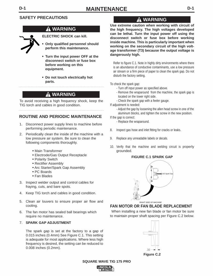
7. SPARK GAP ADJUSTMENT
The spark gap is set at the factory to a gap of0.015 inches (0.4mm) See Figure C.1. This settingis adequate for most applications. Where less highfrequency is desired, the setting can be reduced to0.008 inches (0.2mm).
SAFETY PRECAUTIONS
ROUTINE AND PERIODIC MAINTENANCE
WARNING
WARNING
Use extreme caution when working with circuit ofthe high frequency. The high voltages developedcan be lethal. Turn the input power off using thedisconnect switch or fuse box before workinginside machine. This is particularly important whenworking on the secondary circuit of the high volt-age transformer (T3) because the output voltage isdangerously high.
Refer to figure C.1. Note in highly dirty environments where thereis an abundance of conductive contaminants, use a low pressureair stream or a firm piece of paper to clean the spark gap. Do notdisturb the factory setting.
To check the spark gap:- Turn off input power as specified above.- Remove the wraparound from the machine, the spark gap is
located on the lower right side.- Check the spark gap with a feeler gauge.
If adjustment is needed:- Adjust the gap by loosening the allen head screw in one of the
aluminum blocks, and tighten the screw in the new position.If the gap is correct:
- Replace the wraparound.
8. Inspect gas hose and inlet fitting for cracks or leaks.
9. Replace any unreadable labels or decals.
10. Verify that the machine and welding circuit is properlygrounded.
.015 Spark Gap
RIGHT SIDE OF MACHINE
FIGURE C.1 SPARK GAP
FAN MOTOR OR FAN BLADE REPLACEMENTWhen installing a new fan blade or fan motor be sure
to maintain proper shaft spacing per Figure C.2 below.
.30
Figure C.2
WARNING

DO NOT use a volt-ohm meter to measure output voltages in TIG mode. TheHigh Frequency Arc Starter voltage can damage the meter.
CAUTION
E-1TROUBLESHOOTINGE-1
If for any reason you do not understand the test procedures or are unable to perform the tests/repairs safely, contact your LocalLincoln Authorized Field Service Facility for technical troubleshooting assistance before you proceed.
CAUTION
This Troubleshooting Guide is provided to help youlocate and repair possible machine malfunctions.Simply follow the three-step procedure listed below.
Step 1. LOCATE PROBLEM (SYMPTOM).Look under the column labeled “PROBLEM (SYMP-TOMS)”. This column describes possible symptomsthat the machine may exhibit. Find the listing that bestdescribes the symptom that the machine is exhibiting.
Step 2. POSSIBLE CAUSE.The second column labeled “POSSIBLE CAUSE” liststhe obvious external possibilities that may contribute tothe machine symptom.
Step 3. RECOMMENDED COURSE OF ACTION
This column provides a course of action for thePossible Cause, generally it states to contact yourlocal Lincoln Authorized Field Service Facility.
If you do not understand or are unable to perform theRecommended Course of Action safely, contact yourlocal Lincoln Authorized Field Service Facility.
HOW TO USE TROUBLESHOOTING GUIDE
Service and Repair should only be performed by Lincoln Electric Factory Trained Personnel.Unauthorized repairs performed on this equipment may result in danger to the technician and machineoperator and will invalidate your factory warranty. For your safety and to avoid Electrical Shock, pleaseobserve all safety notes and precautions detailed throughout this manual.
__________________________________________________________________________
WARNING

E-2TROUBLESHOOTINGE-2
SQUARE WAVE TIG 175 PRO
Observe all Safety Guidelines detailed throughout this manual
If for any reason you do not understand the test procedures or are unable to perform the tests/repairs safely, contact your LocalLincoln Authorized Field Service Facility for technical troubleshooting assistance before you proceed.
CAUTION
OUTPUT PROBLEMS
PROBLEMS(SYMPTOMS)
POSSIBLE AREAS OFMISADJUSTMENTS
RECOMMENDEDCOURSE OF ACTION
Machine is Dead - No Output - No Fan
Fan runs - No output from machinein either Stick or TIG modes.
Fan runs - No output from machinein either Stick or TIG modes and theyellow light on the control panel ison.
Machine does not respond (no gasflow, no high frequency and no opencircuit voltage) when arc start switchor Amptrol is activated - fan is work-ing.
1. Make certain that the input power switch is in the “ON”position and machine is plugged in.
2. Check the input voltage at themachine. Input voltage mustmatch the rating plate and voltageconnection. Refer to ReconnectProcedure in the Installation sec-tion of this manual.
3. Blown or missing fuses in input line.
1. Check for proper input voltagesper nameplate and voltagereconnection.
2. Check to make sure polarityswitch is not in between twopositions.
1. Welding application may haveexceed the recommended dutycycle. Allow the unit to run untilthe fan cools the unit and theyellow light goes out.
1. Machine MUST be in the TIG Mode.
2. The Amptrol may be defective.Check for continuity betweenpins “D” and “E” on cable con-nector when Amptrol isdepressed.
Contact your Local Lincoln AuthorizedField Service Facility for technicaltroubleshooting assistance.

E-3TROUBLESHOOTINGE-3
SQUARE WAVE TIG 175 PRO
Observe all Safety Guidelines detailed throughout this manual
If for any reason you do not understand the test procedures or are unable to perform the tests/repairs safely, contact your LocalLincoln Authorized Field Service Facility for technical troubleshooting assistance before you proceed.
CAUTION
OUTPUT PROBLEMS
PROBLEMS(SYMPTOMS)
POSSIBLE AREAS OFMISADJUSTMENTS
RECOMMENDEDCOURSE OF ACTION
Machine regularly over heats - ther-mostat opens, Yellow light on frontpanel glows. The fan runs butmachine has no output.
1. Welding application may exceed recommended duty cycle. Reduce the duty cycle.
2. Dirt and dust may have clogged the cooling channels inside the machine. Blow out unit with clean, dry low pressure air.
3. Air intake and exhaust louvers may be blocked due to inadequate clearance around machine.
Contact your Local Lincoln AuthorizedField Service Facility for technicaltroubleshooting assistance.

E-4TROUBLESHOOTINGE-4
SQUARE WAVE TIG 175 PRO
Observe all Safety Guidelines detailed throughout this manual
If for any reason you do not understand the test procedures or are unable to perform the tests/repairs safely, contact your LocalLincoln Authorized Field Service Facility for technical troubleshooting assistance before you proceed.
CAUTION
TIG MODE PROBLEMS
PROBLEMS(SYMPTOMS)
POSSIBLE AREAS OFMISADJUSTMENTS
RECOMMENDEDCOURSE OF ACTION
Machine output is intermittently lost.Gas flow and high frequency arealso interrupted.
Arc “Flutters” when TIG welding.
Arc “Pulsates” when AC TIGwelding.
1. Problem may be caused by highfrequency interference. Makesure that the machine is ground-ed properly according to theinstallation instructions. If thereare other high frequencysources in the area, make cer-tain that they are groundedproperly.
2. Check Amptrol for proper opera-tion and loose connections.
3. Check for proper input voltageand proper voltage reconnec-tion.
1. Tungsten electrode may be toolarge in diameter for the currentsetting.
2. Tungsten not “sharp” whenwelding in DC - mode.
3. Gas shielding may be insuffi-cient. Increase gas flow; reducetungsten stickout beyond gascup.
4. Check for contaminated gas orleaks in the gas line, torch, orconnections
5. If a helium blend is used as ashielding gas, then reduce thepercentage of helium.
1. Micro Switch mounted onPolarity Switch is not opening in“AC” mode.
Contact your Local Lincoln AuthorizedField Service Facility for technicaltroubleshooting assistance.
APR96

E-5TROUBLESHOOTINGE-5
SQUARE WAVE TIG 175 PRO
Observe all Safety Guidelines detailed throughout this manual
If for any reason you do not understand the test procedures or are unable to perform the tests/repairs safely, contact your LocalLincoln Authorized Field Service Facility for technical troubleshooting assistance before you proceed.
CAUTION
TIG WELDING PROBLEMS
PROBLEMS(SYMPTOMS)
POSSIBLE AREAS OFMISADJUSTMENTS
RECOMMENDEDCOURSE OF ACTION
Black areas along weld bead.
Weak high frequency - machine hasnormal welding output.
High frequency “spark” is present attungsten electrode, but operator isunable to establish a welding arc.Machine has normal open circuitvoltage (refer to TechnicalSpecifications in the InstallationChapter).
1. Clean any oily or organic conta-mination from the work piece.
2. Tungsten electrode may be cont-aminated. Replace or sharpen.
3. Check for contaminated gas orleaks in the gas line, torch, orconnections
4. Gas shielding may be insuffi-cient. Increase gas flow; reducetungsten stickout beyond gascup.
1. Check for poor connections inthe welding circuit.
2. Gas shielding may be insuffi-cient. Increase gas flow; reducetungsten stickout beyond gascup.
3. Check for work and electrodecables in poor condition allowinghigh frequency to “Leak Off”.
4. Keep cables as short as possible.
5. Check Spark Gap operation andsetting (0.015”)
1. The tungsten electrode may becontaminated. Replace or sharp-en.
2. The current control may be settoo low.
3. The tungsten electrode may betoo large for the process.
4. If a helium blend is used as ashielding gas, then reduce thepercentage of helium.
Contact your Local Lincoln AuthorizedField Service Facility for technicaltroubleshooting assistance.

E-6TROUBLESHOOTINGE-6
SQUARE WAVE TIG 175 PRO
Observe all Safety Guidelines detailed throughout this manual
If for any reason you do not understand the test procedures or are unable to perform the tests/repairs safely, contact your LocalLincoln Authorized Field Service Facility for technical troubleshooting assistance before you proceed.
CAUTION
TIG WELDING PROBLEMS
PROBLEMS(SYMPTOMS)
POSSIBLE AREAS OFMISADJUSTMENTS
RECOMMENDEDCOURSE OF ACTION
No high frequency. Machine is inthe TIG Mode and has normal out-put.
No gas flow when Amptrol is activat-ed in the TIG Mode. Machine hasoutput - fan runs. A “Click” can beheard indicating that the gas sole-noid valve is operating.
When AC TIG welding, the arc iserratic and there is a loss of “clean-ing” of the work piece.
The end of the tungsten electrodemelts away.
1. If the machine location is in ahighly dirty environment withconductive contaminants, checkand clean the spark gap with alow pressure air stream per themaintenance instructions.
1. Gas supply is empty or not turned on.
2. Flow regulator may be set toolow.
3. Gas hose may be pinched.
4. Gas flow may be blocked withdirt. Check filter screen insidegas inlet fitting to solenoid valve.Use filters to prevent reoccur-rence.
5. Consult your local welder/gas distributor.
1. Tungsten electrode may be toosmall for process. Use a largerdiameter tungsten or a puretungsten.
2. If a helium blend is used as ashielding gas, then reduce thepercentage of helium.
1. The welding current is too highfor the electrode type and/orsize. See the Table B.1 in theOperation Section of this manu-al.
Contact your Local Lincoln AuthorizedField Service Facility for technicaltroubleshooting assistance.
E-7TROUBLESHOOTINGE-7
SQUARE WAVE TIG 175 PRO
Observe all Safety Guidelines detailed throughout this manual
If for any reason you do not understand the test procedures or are unable to perform the tests/repairs safely, contact your LocalLincoln Authorized Field Service Facility for technical troubleshooting assistance before you proceed.
CAUTION
STICK WELDING PROBLEMS
PROBLEMS(SYMPTOMS)
POSSIBLE AREAS OFMISADJUSTMENTS
RECOMMENDEDCOURSE OF ACTION
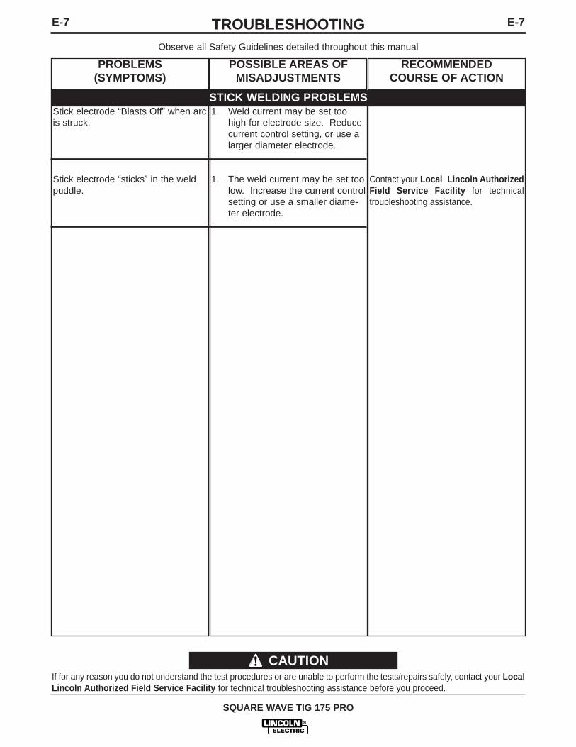
Stick electrode “Blasts Off” when arcis struck.
Stick electrode “sticks” in the weldpuddle.
1. Weld current may be set toohigh for electrode size. Reducecurrent control setting, or use alarger diameter electrode.
1. The weld current may be set toolow. Increase the current controlsetting or use a smaller diame-ter electrode.
Contact your Local Lincoln AuthorizedField Service Facility for technicaltroubleshooting assistance.

F-1WIRING DIAGRAMF-1
SQUARE WAVE TIG 175 PRO
(-)
(+)
SC
R4
SC
R2
SC
R1
D
C
B
A
FEDCBA
+-
REA
R G
ANG
L1
(-)EL
ECTR
OD
E
T4
NC
NO
MIC
RO
-SW
ITC
H
T3
S F
L3 L4
C3
SC
R3
115V
ACYW
H1
X1
H
G
311
312
OPE
NC
LOSE
DC
LOSE
D
G4
216
G3
218
G2
G1
217
220
X2
FRO
NT
GAN
G E
F
PC
BO
ARD
THER
MAL
LIG
HT
J5
CO
NTR
OL
PC B
OAR
D
D1
J3
INPU
T PL
UG
PL1
S2
R1
S3
MO
DE
SWIT
CH
TL1
SV
1
GAS
VAL
VE
S2A
BYP
ASS/
STAB
ILIZ
ER
H1
X1 X2
FAN
R 2
22W
221
( STI
CK
- C
LOSE
DTI
G -
OPE
N )
WO
RK
R2
ARC
STA
RTE
R A
S’B
LY
236A
237
C4
R3
S F
S F
W 221 (+)
R 222 (-)
J1J2
313
314
277
276
275
277
276
275
241
244
242
243
231
233
311
312
243
244
231
233
A B C D EBCD AE
TIG
STIC
K
234
235
234235
210
232
204
236
209
230
238
201
J6
236B
217
218
G3
216
G1
G2
220
G4
POW
ER "
ON
" LI
GH
T
236A
REM
OTE
REC
EPTA
CLE
REM
OTE
AMPT
RO
L
J4
B-B
LAC
K
R-R
EDY-
YELL
OW
G-G
REE
NU
-BLU
EW
-WH
ITE
LEAD
CO
LOR
ING
CO
DE:
CO
NN
ECTO
R P
IN N
UM
BER
S:
VIEW
OF
CO
NN
ECTO
R O
N P
C B
OAR
D
12
37
814
D1
MIC
ROSW
ITCH
ON
POLA
RITY
SW
ITCH
T1
MAI
N T
RAN
SFO
RM
ER
LATC
H
SCR
1,2,
3,4
FREE
WH
EELI
NG
DIO
DE
S2A
O-O
RAN
GE
L1 L2C3
MAI
N S
CR
s
T3 T4H
IGH
VO
LTAG
E TR
ANSF
OR
MER
L3,L
4H
I-FR
EQ IN
DU
CTO
RS
HIGH
VOL
TAGE
CAP
ACIT
OR, .
0015
/12k
V
HI-
FREQ
TR
ANSF
OR
MER
R1
CU
RREN
T CO
NTRO
L PO
TENT
IOM
ETER
10K
EXAM
PLE:
TH
IS IS
PIN
70F
CO
NN
ECTO
R J
4
C4
R3
R
2
HO
LDIN
G R
ESIS
TOR
50/
100
PHAS
E SH
IFT
RES
ISTO
R 2
00/1
00
PL1
POW
ER "
ON
" LI
GH
T, 1
15VA
C
HI-F
REQ
PROT
ECTI
ON C
HOKE
(TOR
OID)
SV1
TL1
THER
MAL
LIG
HT,
LED
CO
MPO
NEN
T VA
LUE
UN
ITS:
RES
ISTO
RS:
CAP
ACIT
OR
S:O
HM
S/W
ATTS
MFD
/VO
LTS
J4
PHAS
E SH
IFT C
APAC
ITOR
15u
F/25
0VAC
OU
TPU
T IN
DU
CTO
R (C
HO
KE)
GAS
SO
LEN
OID
, 115
VAC
SPAR
KG
AP
B
B
AC DC
+D
C-
A-C
, D-E
, B-F
B-D
, C-E
, A-F
, G-H
B-D
, A-E
, C-F
, G-H
POLA
RIT
Y SW
ITC
H
MIC
RO
SW
ITC
H
(REA
R V
IEW
,SH
OW
N IN
AC
PO
SITI
ON
)
115V
AC11
5VAC
18VA
C
18VA
C
78VA
C
T1
L1L2
TO G
RO
UN
D P
ER
POLA
RIT
YSW
ITC
H
ELEC
TRIC
AL S
YMB
OLS
PER
E15
37.
TM
CU
RR
ENT
CO
NTR
OL
POW
ERSW
ITC
H
H3
H2
H3
(230
V)
H2
(208
V)
NAT
ION
AL E
LEC
TRIC
AL C
OD
E
VOLT
AGE
REC
ON
NEC
TIO
N
230
VOLT
CO
NN
ECTI
ON
(AS
SHO
WN
)H
1 an
d H
3 TO
PO
WER
SW
ITC
H.
208
VOLT
CO
NN
ECTI
ON
H1
and
H2
TO P
OW
ER S
WIT
CH
.H
3 N
OT
CO
NN
ECTE
D:
INSU
LATE
.
H2
NO
T C
ON
NEC
TED
; IN
SULA
TE.
238
236
TOR
OID
L2
POS
THER
MO
STAT
THER
MO
STAT
CH
OK
E
SCR
HEA
TSIN
K
B X4
W X
5
W X
3
W X
6B
X7 B X8
10K
A-B
AT M
INIM
UM
C1,
C2
BY-P
ASS
CAPA
CITO
RS
C2
C1
C1
AND
C2
MU
ST A
LWAY
S B
EC
ON
NEC
TED
AC
RO
SS P
OW
ER S
WIT
CH
.
209
210
201
204
230
232
241
242
WIR
ING
DIA
GR
AM
- S
QU
AR
E W
AV
E T
IG 1
75
PR
O (2
08
/ 2
30
/ 1
/ 6
0)
TIG
PULS
ERO
R
F
F
1-00
L1
0060
-1
NO
TE
: T
his
dia
gra
m is
fo
r re
fere
nce
onl
y.
It m
ay n
ot
be
accu
rate
fo
r al
l mac
hine
s co
vere
d b
y th
is m
anua
l. T
he s
pec
ific
dia
gra
m f
or
a p
artic
ular
co
de
is p
aste
din
sid
e th
e m
achi
ne o
n o
ne o
f th
e en
clo
sure
pan
els.
If
the
dia
gra
m is
ille
gib
le, w
rite
to
the
Ser
vice
Dep
artm
ent
for
a re
pla
cem
ent.
G
ive
the
equi
pm
ent
cod
e nu
mb
er..

F-2WIRING DIAGRAMF-2
SQUARE WAVE TIG 175 PRO
L1L2
241
TL
1
THER
MO
STAT
242
CO
NTR
OL
PC B
OAR
D
H1
T1
78VA
C
18VA
C
18VA
C
115V
AC
POLA
RIT
YSW
ITC
H
PL
1
W X
5B
X4W X
3
HIGH
VOL
TAGE
CAP
ACIT
OR, .
0015
/12k
V
H2
(460
V)
H3
(575
V)
C2
C1
PULS
ER
GAS
SO
LEN
OID
, 115
VAC
OU
TPU
T IN
DU
CTO
R (C
HO
KE)
PHAS
E SH
IFT
CAPA
CITO
R 15
uF/2
50VA
CC
4C
3
B
B
GAP
SPAR
K
B-D
, A-E
, C-F
, G-H
B-D
, C-E
, A-F
, G-H
A-C
, D-E
, B-F
DC
-
216
TMO
RTI
G
ELEC
TRIC
AL S
YMB
OLS
PER
E15
37.
VIEW
OF
CO
NN
ECTO
R O
N P
C B
OAR
D
CO
NN
ECTO
R P
IN N
UM
BER
S:
236A
J6
G4
209
238
210230232238
POS
234235204201236
216
L10
569-
1
311
312
G1
X1
G2
X221
7
H2
220
G3
218
1-00
W X
6B
X7 B X8
NC
NO
OPE
NC
LOSE
DC
LOSE
D
MIC
RO
-SW
ITC
H
(-)
G
H
BY-P
ASS
CAPA
CITO
RS
FRO
NT
GAN
G E
F
C1,
C2
S F
FS
H3
NO
T C
ON
NEC
TED
: IN
SULA
TE.
H1
and
H2
TO P
OW
ER S
WIT
CH
.
C1
AND
C2
MU
ST A
LWAY
S B
E
460
VOLT
CO
NN
ECTI
ON
CO
NN
ECTE
D A
CR
OSS
PO
WER
SW
ITC
H.
H2
NO
T C
ON
NEC
TED
; IN
SULA
TE.
H1
and
H3
TO P
OW
ER S
WIT
CH
.57
5 VO
LT C
ON
NEC
TIO
N (A
S SH
OW
N)
VOLT
AGE
REC
ON
NEC
TIO
N
POW
ER "
ON
" LI
GH
T31
431
3
W 221 (+)
R 222 (-)
WIR
ING
DIA
GR
AM
-
SQ
UA
RE
WA
VE
TIG
17
5 P
RO
(4
60
/57
5/1
/60
)
D
235
GAS
VAL
VE
REA
R G
ANG
B
A
C
FEDCBA
-+
D1
U-B
LUE
W-W
HIT
EY-
YELL
OW
L1 L2 LEAD
CO
LOR
ING
CO
DE:
B-B
LAC
KG
-GR
EEN
R-R
ED
(-)
T4
C3
ELEC
TRO
DE
L3
S
L4
T3
F
J4LA
TCH
EXAM
PLE:
TH
IS IS
PIN
7
MFD
/VO
LTS
1
OH
MS/
WAT
TSC
APAC
ITO
RS:
RES
ISTO
RS:
U
NIT
S:C
OM
PON
ENT
VALU
E
THER
MAL
LIG
HT,
LED
HI-
FREQ
TR
ANSF
OR
MER
O-O
RAN
GE
HIG
H V
OLT
AGE
TRAN
SFO
RM
ERM
AIN
TR
ANSF
OR
MER
MAI
N S
CR
sM
ICRO
SWIT
CH O
N PO
LARI
TY S
WIT
CHPH
ASE
SHIF
T R
ESIS
TOR
200
/100
HO
LDIN
G R
ESIS
TOR
50/
100
TL1
CURR
ENT
CONT
ROL
POTE
NTIO
MET
ER 1
0K
T4
POW
ER "
ON
" LI
GH
T, 1
15VA
C
T3
HI-
FREQ
IND
UC
TOR
S
T1
HI-F
REQ
PROT
ECTI
ON C
HOKE
(TOR
OID)
SV1
SCR
1,2,
3,4
FREE
WH
EELI
NG
DIO
DE
S2A
R3
R
2
R1
PL
1L3
,L4
G4
PER
NAT
ION
AL E
LEC
TRIC
CO
DE.
CO
NN
ECT
BLA
CK
AN
D W
HIT
E LE
ADS
TO S
UPP
LYC
IRC
UIT
.
N.A
. C
ON
NEC
T G
REE
N/Y
ELLO
W L
EAD
TO
GR
OU
ND
236
SV
1 234
147
8
32
0F C
ON
NEC
TOR
J4
115V
AC
L1
SC
R4
Y
SC
R3(+)
SC
R2
SC
R1
H3
R2
WO
RK
233 27
727
6
231
312
244
311
242
241
ARC
STA
RTE
R A
S’B
LY
233
275
231
276
243
237
C4
277
R3
236A
CU
RR
ENT
CO
NTR
OL
TOR
OID
L2
SHO
WN
IN A
C P
OSI
TIO
N)
(REA
R V
IEW
,
X2X1
DC
+
POLA
RIT
Y SW
ITC
H
MIC
RO
SW
ITC
HAC
232
230
204
201
210
209
115V
AC
( STI
CK
- C
LOSE
DTI
G -
OPE
N )
THER
MAL
LIG
HT
217G1218G2G3220
TIG
236B
J1
10K
A-B
AT M
INIM
UM
A B
S2A
H1
S2
FAN
D1
BYP
ASS/
STAB
ILIZ
ER P
C B
OAR
D
R 2
22W
221
R1
S3
J3
MO
DE
SWIT
CH
275 ST
ICK
243
244
J2
W
AMPT
RO
LR
EMO
TER
ECEP
TAC
LER
EMO
TE
J4
C D E F
E D F C A B
J5
CH
OK
E
THER
MO
STAT
SCR
HEA
TSIN
K
{
SWIT
CH
POW
ER
CO
NN
ECT
GR
EEN
LEA
D T
O G
RO
UN
DPE
R N
ATIO
NAL
ELE
CTR
IC C
OD
E. C
ON
NEC
TB
LAC
K A
ND
WH
ITE
LEAD
S TO
SU
PPLY
CIR
CU
IT.
NO
TE
: T
his
dia
gra
m is
fo
r re
fere
nce
onl
y.
It m
ay n
ot
be
accu
rate
fo
r al
l mac
hine
s co
vere
d b
y th
is m
anua
l. T
he s
pec
ific
dia
gra
m f
or
a p
artic
ular
co
de
is p
aste
din
sid
e th
e m
achi
ne o
n o
ne o
f th
e en
clo
sure
pan
els.
If
the
dia
gra
m is
ille
gib
le, w
rite
to
the
Ser
vice
Dep
artm
ent
for
a re
pla
cem
ent.
G
ive
the
equi
pm
ent
cod
e nu
mb
er..

NOTES
SQUARE WAVE TIG 175 PRO

Now Available...12th EditionThe Procedure Handbook of Arc Welding
With over 500,000 copies of previous editions publishedsince 1933, the Procedure Handbook is considered by many to be the “Bible” of the arc welding industry.
This printing will go fast so don’t delay. Place your order now using the coupon below.
The hardbound book contains over 750 pages of weldinginformation, techniques and procedures. Much of this material has never been included in any other book.
A must for all welders, supervisors, engineers anddesigners. Many welding instructors will want to use the book asa reference for all students by taking advantage of the low quan-tity discount prices which include shipping by4th class parcel post.
$15.00 postage paid U.S.A. Mainland
How To Read Shop Drawings
The book contains the latest information and applicationdata on the American Welding Society Standard WeldingSymbols. Detailed discussion tells how engineers and drafts-men use the “short-cut” language of symbols to pass onassembly and welding information to shop personnel.
Practical exercises and examples develop the reader’s abilityto visualize mechanically drawn objects as they will appear intheir assembled form.
187 pages with more than 100 illustrations. Size 8-1/2” x 11”Durable, cloth-covered board binding.
$4.50 postage paid U.S.A. Mainland
New Lessons in Arc WeldingLessons, simply written, cover manipulatory techniques;
machine and electrode characteristics; related subjects, suchas distortion; and supplemental information on arc weldingapplications, speeds and costs. Practice materials, exercis-es, questions and answers are suggested for each lesson.
528 pages, well illustrated, 6” x 9” size, bound in simulated,gold embossed leather.
$5.00 postage paid U.S.A. Mainland
Need Welding Training?The Lincoln Electric Company operates the oldest and
most respected Arc Welding School in the United States at itscorporate headquarters in Cleveland, Ohio. Over 100,000 studentshave graduated. Tuition is low and the training is “hands on”
For details write: Lincoln Welding School22801 St. Clair Ave. Cleveland, Ohio 44117-1199.
and ask for bulletin ED-80 or call 216-383-2259 and ask for theWelding School Registrar.
Lincoln Welding SchoolBASIC COURSE $700.00
5 weeks of fundamentalsThere is a 10% discount on all orders of $50.00 or more for shipment at one time to one location.Orders of $50 or less before discount or orders outside of North America must be prepaid with charge, check or money order in U.S. Funds Only.Prices include shipment by 4 th Class Book Rate for U.S.A. Mainland Only. Please allow up to 4 weeks for delivery.UPS Shipping for North America Only. All prepaid orders that request UPS shipment please add:
$5.00 For order value up to $49.99$10.00 For order value between $50.00 & $99.99$15.00 For order value between $100.00 & $149.00
For North America invoiced orders over $50.00 & credit card orders, if UPS is requested, it will be invoiced or charged to you at cost.Outside U.S.A. Mainland order must be prepaid in U.S. Funds. Please add $2.00 per book for surface mail or $15.00 per book for air parcel post shipment.METHOD OF PAYMENT: (Sorry, No C.O.D. Orders)
CHECK ONE:Name: _______________________________________________
Please Invoice (only if order is over $50.00)Address: _______________________________________________
Check or Money Order Enclosed, U.S. Funds only _______________________________________________
Credit Card - Telephone: _______________________________________________
Signature as it appears on Charge Card:Account No. |_|_|_|_|_|_|_|_|_|_|_|_|_|_|_|_|_|_|_|_|_| Exp Date |_|_| |_|_| ______________________Month Year
USE THIS FORM TO ORDER: Order from: BOOK DIVISION, The Lincoln Electric Company, 22801 St. Clair Avenue, Cleveland, Ohio 44117-1199BOOKS OR FREE INFORMATIVE CATALOGS Telephone: 216-383-2211 or, for fastest service, FAX this completed form to: 216-361-5901.
Lincoln Welding School Titles: Price Code Quantity Cost(ED-80) New Lessons in Arc Welding $5.00 L
Seminar Information Procedure Handbook “Twelfth Edition” $15.00 PH(ED-45) How to Read Shop Drawings $4.50 H
Educational Video Information Incentive Management $5.00 IM(ED-93) A New Approach to Industrial Economics $5.00 NA
James F. Lincoln Arc Welding The American Century of John C. Lincoln $5.00 ACFoundation Book Information Welding Preheat Calculator $3.00 WC-8
(JFLF-515) Pipe Welding Charts $4.50 ED-89SUB TOTAL
Additional Shipping Costs if anyTOTAL COST
MasterCard
VISA ®
AMERICAN EXPRESS
MasterCardMasterCard®
AMERICAN EXPRESS

WARNING
AVISO DEPRECAUCION
ATTENTION
WARNUNG
ATENÇÃO
Spanish
French
German
Portuguese
Japanese
Chinese
Korean
Arabic
READ AND UNDERSTAND THE MANUFACTURER’S INSTRUCTION FOR THIS EQUIPMENT AND THE CONSUMABLES TOBE USED AND FOLLOW YOUR EMPLOYER’S SAFETY PRACTICES.
SE RECOMIENDA LEER Y ENTENDER LAS INSTRUCCIONES DEL FABRICANTE PARA EL USO DE ESTE EQUIPO Y LOSCONSUMIBLES QUE VA A UTILIZAR, SIGA LAS MEDIDAS DE SEGURIDAD DE SU SUPERVISOR.
LISEZ ET COMPRENEZ LES INSTRUCTIONS DU FABRICANT EN CE QUI REGARDE CET EQUIPMENT ET LES PRODUITS AETRE EMPLOYES ET SUIVEZ LES PROCEDURES DE SECURITE DE VOTRE EMPLOYEUR.
LESEN SIE UND BEFOLGEN SIE DIE BETRIEBSANLEITUNG DER ANLAGE UND DEN ELEKTRODENEINSATZ DES HER-STELLERS. DIE UNFALLVERHÜTUNGSVORSCHRIFTEN DES ARBEITGEBERS SIND EBENFALLS ZU BEACHTEN.
● Do not touch electrically live parts orelectrode with skin or wet clothing.
● Insulate yourself from work andground.
● No toque las partes o los electrodosbajo carga con la piel o ropa moja-da.
● Aislese del trabajo y de la tierra.
● Ne laissez ni la peau ni des vête-ments mouillés entrer en contactavec des pièces sous tension.
● Isolez-vous du travail et de la terre.
● Berühren Sie keine stromführendenTeile oder Elektroden mit IhremKörper oder feuchter Kleidung!
● Isolieren Sie sich von denElektroden und dem Erdboden!
● Não toque partes elétricas e elec-trodos com a pele ou roupa molha-da.
● Isole-se da peça e terra.
● Keep flammable materials away.
● Mantenga el material combustiblefuera del área de trabajo.
● Gardez à l’écart de tout matérielinflammable.
● Entfernen Sie brennbarres Material!
● Mantenha inflamáveis bem guarda-dos.
● Wear eye, ear and body protection.
● Protéjase los ojos, los oídos y elcuerpo.
● Protégez vos yeux, vos oreilles etvotre corps.
● Tragen Sie Augen-, Ohren- und Kör-perschutz!
● Use proteção para a vista, ouvido ecorpo.
WARNING
AVISO DEPRECAUCION
ATTENTION
WARNUNG
ATENÇÃO
Spanish
French
German
Portuguese
Japanese
Chinese
Korean
Arabic
LEIA E COMPREENDA AS INSTRUÇÕES DO FABRICANTE PARA ESTE EQUIPAMENTO E AS PARTES DE USO, E SIGA ASPRÁTICAS DE SEGURANÇA DO EMPREGADOR.
● Keep your head out of fumes.● Use ventilation or exhaust to
remove fumes from breathing zone.
● Los humos fuera de la zona de res-piración.
● Mantenga la cabeza fuera de loshumos. Utilice ventilación oaspiración para gases.
● Gardez la tête à l’écart des fumées.● Utilisez un ventilateur ou un aspira-
teur pour ôter les fumées des zonesde travail.
● Vermeiden Sie das Einatmen vonSchweibrauch!
● Sorgen Sie für gute Be- undEntlüftung des Arbeitsplatzes!
● Mantenha seu rosto da fumaça.● Use ventilação e exhaustão para
remover fumo da zona respiratória.
● Turn power off before servicing.
● Desconectar el cable de ali-mentación de poder de la máquinaantes de iniciar cualquier servicio.
● Débranchez le courant avant l’entre-tien.
● Strom vor Wartungsarbeitenabschalten! (Netzstrom völlig öff-nen; Maschine anhalten!)
● Não opere com as tampas removidas.● Desligue a corrente antes de fazer
serviço.● Não toque as partes elétricas nuas.
● Do not operate with panel open orguards off.
● No operar con panel abierto oguardas quitadas.
● N’opérez pas avec les panneauxouverts ou avec les dispositifs deprotection enlevés.
● Anlage nie ohne Schutzgehäuseoder Innenschutzverkleidung inBetrieb setzen!
● Mantenha-se afastado das partesmoventes.
● Não opere com os paineis abertosou guardas removidas.

• Sales and Service through Subsidiaries and Distributors Worldwide •Cleveland, Ohio 44117-1199 U.S.A. TEL: 216.481.8100 FAX: 216.486.1751 WEB SITE: www.lincolnelectric.com
• World's Leader in Welding and Cutting Products •


