
2005/04 – Subject to change – Products 2004/2005 1 / 1.2−1
Standard cylinders DNC, ISO 15552
�Standard cylinder with strokes
of up to 2,000 mm
�Latest profile design
�Proximity sensors fit flush in
the sensor slot
�Numerous variants
Specified types in accordance with
ATEX directive for potentially
explosive atmospheres
� www.festo.com/en/ex
ISO
sta
ndar
d cy
linde
rs
ISO
15
55
2 (I
SO
64
31
and
VD
MA
24
56
2)
1.2

Products 2004/2005 – Subject to change – 2005/071 / 1.2−2
Standard cylinders DNC, ISO 15552Key features
Basic cylinder DNC
General data
� Standardised dimensions
Conforms to
� ISO 15552
� ISO 6431
�VDMA 24562
�NFE 49003.1
�UNI 10290
DIN
� The modern design and construc-
tion saves up to 11% on space
compared to ordinary standard
cylinders, thus permitting a
considerably more compact system
design.
� An extensive range of accessories
makes it possible to install the
cylinder virtually anywhere.
� The widest range of variants on the
market provides the right DNC
cylinder for every application.
� The proximity sensors fit flush in
the profile slot. On the one hand,
this does away with the need for
additional mounting kits and on
the other, it protects the proximity
sensor against mechanical damage.
Design features
� Socket head screw with female
threads for mounting attachments
�No protruding
proximity sensors
� A broad range of
accessories
p y
thanks to profile
slots
� Smooth, closed
surface using slot
covers for the sen-
sor slots (protects
the sensor cable
and keeps dirt out
of the profile slots)
� Additional cushion-
ing rings in the end
positions for ab-
sorbing the residual
energy from high
speeds and
machine cycles.
ISO
sta
ndar
d cy
linde
rs
ISO
15
55
2 (I
SO
64
31
and
VD
MA
24
56
2)
1.2

2005/07 – Subject to change – Products 2004/2005 1 / 1.2−3
Standard cylinders DNC, ISO 15552Key features
Tandem cylinder
DNCT
� Connection of 2 cylinders with the
same piston ∅ and stroke in series
�Double the thrust and return force
in comparison to a standard
cylinder
Cylinder with clamping units
Clamping cartridge for piston rod DNC−KP
�Holding and clamping of piston
rods in any position during clamp-
ing, processing or handling tasks
� Compact design of the clamping
unit
� The piston rod can be held in
position for long periods even with
alternating loads, fluctuating
operating pressure or leaks in the
system
�With own modular product system
Cylinders with clamping unit DNCKE
�Used in safety relevant control
systems EN 954−1, EN 1050,
EN 292 and EN 983
� Zero−fault proof
� Piston rod can be clamped in any
position
ISO
sta
ndar
d cy
linde
rs
ISO
15
55
2 (I
SO
64
31
and
VD
MA
24
56
2)
1.2

Products 2004/2005 – Subject to change – 2005/071 / 1.2−4
Standard cylinders DNC, ISO 15552Key features
Cylinder with end−position lock
Cylinder DNC− Ī −EL
�Mechanical lock when the end
position is reached
� Lock is only automatically released
when pressure is supplied to the
cylinder
� End position locking in advanced,
retracted or both end positions
� The end position lock does not
require any additional valves or
sensors for actuation as is the case
with other force−locked systems
Cylinder/valve combination
DNC−V1 Ī −V6
� The drive unit is fitted and tubed,
ready for connection, with a CPE
solenoid valve and one−way flow
control valves
�Quick installation of drive unit
� Particularly suitable for decentra-
lised use in larger systems
�With own modular product system
ISO
sta
ndar
d cy
linde
rs
ISO
15
55
2 (I
SO
64
31
and
VD
MA
24
56
2)
1.2

2005/07 – Subject to change – Products 2004/2005 1 / 1.2−5
Standard cylinders DNC, ISO 15552Key features
Variants from the modular system
Symbol Key features Description
Q Square piston rod Protection against torsion
S2 Through piston rod The thread designs on both piston rod ends are identical
S20 Through, hollow piston rod Suitable for vacuum applications
K2 Extended male piston rod thread –
K3 Female piston rod thread –
K5 Special thread on piston rod Metric standard thread to ISO
K7 Piston rod with external hexagon Special spanner flats
K8 Extended piston rod –
K10 Smooth anodised aluminium piston rod Ideal for use in welding environments:
— Protection against welding spatter
— Small moving loads
— Harder surface compared to steel
— Long service life
S6 Heat−resistant seals for temperatures up to
150 °C
Temperature−resistant
S10 Slow speed (constant motion at low piston
speeds)
Suitable for slow stroke movements at a constant, stick−slip−free speed over the
full stroke of the cylinder.
Seal contains silicone grease (not free of paint−wetting impairment
substances).
S11 Low friction The special seals considerably reduce system wear. This corresponds to a
considerably lower response pressure.
Seal contains silicone grease (not free of paint−wetting impairment
substances).
CT−free
CT Free of copper, PTFE and silicone –
R3 High corrosion protection All external cylinder surfaces comply with corrosion resistance class 3 to Festo
standard 940 070. The piston rod is made from corrosion and acid resistant
steel.
ÓÓÓÓÓÓÓÓÓÓÓÓÓÓÓ
R8 Dust protection using wiper seals The cylinder is equipped with a hard−chrome plated piston rod and a rigid
scraper, which protects against dry, dusty media.
KP With clamping cartridge Integrated clamping unit on piston rod
EL With end position lock Positive−locking end position lock as drop guard for safety−related
applications. If there is a drop in pressure, the piston rod is secured in its end
position to prevent it from dropping.
Software tools on CD−ROM:
Configuration of Festo product
modules
www.festo.com
ISO
sta
ndar
d cy
linde
rs
ISO
15
55
2 (I
SO
64
31
and
VD
MA
24
56
2)
1.2

Products 2004/2005 – Subject to change – 2005/071 / 1.2−6
Standard cylinders DNC, ISO 15552Product range overview
Function Design Type Piston � Stroke Position
sensing
Protec-
tion
against
torsion
Type of
piston
rod
Male
thread
extended
Female
thread
Special
thread
[mm] [mm] A Q S2/S20 K2 K3 K5
Double− Basic cylinder
acting DNC 32, 40, 25, 40, 50, 80, 10 Ī 2,000g
50, 63,
5, , 5 , ,
100, 125, 160,
,
� � � � � �80, 100,
, , ,
200, 250, 320,� � � � � �
125
, , ,
400, 500
Tandem/high−power cylinder
DNCT 32, 40, – 2 Ī 500
50
5
� – – – – –63, 80, 3 Ī 500
� – – – – –
100, 125
3 5
Cylinder with clamping units
DNC−KP 32, 40, – 10 Ī 2,000
50, 63,
,
� ��
� � �80, 100,
� �S2
� � �
125
DNCKE 40, 63, – 10 Ī 2,000
100
,
� – – – – –� – – – – –
Cylinder with end−position lock
DNC−Ī−EL 32, 40, – 10 Ī 2,000
50, 63,
,
� –�
� � �80, 100
� –S2
� � �
Cylinder/valve combination
DNC−V1 Ī V6 32, 40, – 100 Ī 2,000
50, 63,
,
� � � � � �80, 100
� � � � � �
ISO
sta
ndar
d cy
linde
rs
ISO
15
55
2 (I
SO
64
31
and
VD
MA
24
56
2)
1.2

2005/07 – Subject to change – Products 2004/2005 1 / 1.2−7
Standard cylinders DNC, ISO 15552Product range overview
Type Special
spanner
flats
Piston rod
extended
Improved
running
perform-
ance
Heat−resis-
tant up to
150 °C
Constant
motion (at
low speed)
Low friction Free of
copper,
PTFE and
silicone
High cor-
rosion
protection
Wiper seal Cylinder/
valve com-
bination
�Page
K7 K8 K10 S6 S10 S11 CT R3 R8 V1 Ī V6
Basic cylinder
DNC 1 / 1.2−12
� � � � � � � � � –� � � � � � � � � –
Tandem/high−power cylinder
DNCT NO TAG
www.festo.com
– – – � – – – – – –
Cylinder with clamping units
DNC−KP 1 / 1.2−26
� � – – – – – – – �� � – – – – – – – �
DNCKE NO TAG
www.festo.com
– – – – – – – – – –
Cylinder with end−position lock
DNC−Ī−EL 1 / 1.2−36
www.festo.com
– � – – – – – – – –
Cylinder/valve combination
DNC−V1 Ī V6 1 / 1.2−44
� � � – � � – – � �� � � – � � – – � �
ISO
sta
ndar
d cy
linde
rs
ISO
15
55
2 (I
SO
64
31
and
VD
MA
24
56
2)
1.2
Products 2004/2005 – Subject to change – 2005/041 / 1.2−8
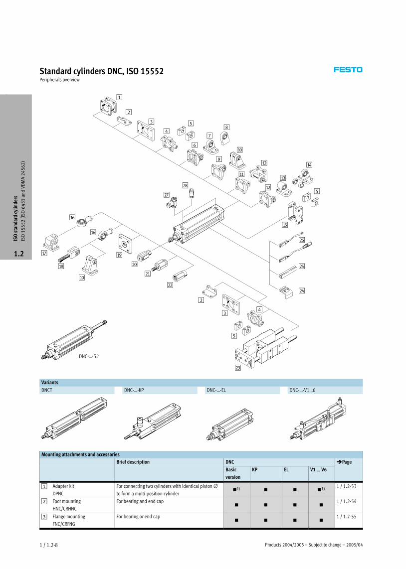
Standard cylinders DNC, ISO 15552Peripherals overview
1
2
3
4
5
6
7
8
9
aJ
aA
aB
aB
aC
aD
aE
aF
aF
aG
aH
aJ
aI
bJ
bA
bB
2
34
bC
bD
bE
bF
bG
bH
5
5
DNC−Ī−S2
Variants
DNCT DNC−Ī−KP DNC−Ī−EL DNC−Ī−V1Ī6
Mounting attachments and accessories
Brief description DNC �Page
Basic
version
KP EL V1 Ī V6
1 Adapter kit
DPNC
For connecting two cylinders with identical piston ∅to form a multi−position cylinder
�1) � � �1)1 / 1.2−53
2 Foot mounting
HNC/CRHNC
For bearing and end cap� � � �
1 / 1.2−54
3 Flange mounting
FNC/CRFNG
For bearing or end cap� � � �
1 / 1.2−55
ISO
sta
ndar
d cy
linde
rs
ISO
15
55
2 (I
SO
64
31
and
VD
MA
24
56
2)
1.2

2005/04 – Subject to change – Products 2004/2005 1 / 1.2−9
Standard cylinders DNC, ISO 15552Peripherals overview
Mounting attachments and accessories
Brief description DNC �Page
Basic
version
KP EL V1 Ī V6
4 Trunnion flange
ZNCF/CRZNG
For bearing or end cap� � � �
1 / 1.2−56
5 Trunnion support
LNZG/CRLNZG
–� � � �
1 / 1.2−58
6 Swivel flange
SNC
For end cap�1) �1) � �1)
1 / 1.2−59
7 Clevis foot
LSNG
With spherical bearing�1) �1) � �1)
1 / 1.2−62
8 Clevis foot
LSNSG
Weld−on, with spherical bearing�1) �1) � �1)
1 / 1.2−62
9 Swivel flange
SNCS
With spherical bearing for end caps�1) �1) � �1)
1 / 1.2−61
aJ Clevis foot
LBG
–�1) � � �1)
1 / 1.2−62
aA Swivel flange
SNCL
For end cap�1) �1) � �1)
1 / 1.2−61
aB Swivel flange
SNCB/SNCB−Ī−R3
For end cap�1) �1) � �1)
1 / 1.2−60
aC Clevis foot
LNG/CRLNG
–�1) �1) � �1)
1 / 1.2−62
aD Clevis foot
LSN
With spherical bearing�1) �1) � �1)
1 / 1.2−62
aE Trunnion mounting kit
ZNCM
For mounting anywhere along the cylinder profile
barrel� � � �
1 / 1.2−57
aF Rod eye
SGS/CRSGS
With spherical bearing� � � �
1 / 1.2−63
aG Clevis foot, lateral
LQG
–� � � �
1 / 1.2−62
aH Rod clevis
SGA
With male thread� � � �
1 / 1.2−63
aI Coupling piece
KSG
For compensating radial deviations� � � �
1 / 1.2−63
Coupling piece
KSZ
For cylinders with a non−rotating piston rod to
compensate for radial deviations
�
Q
�
Q�
�
Q
1 / 1.2−63
bJ Rod clevis
SG/CRSG
Permits a swivelling movement of the cylinder in one
plane� � � �
1 / 1.2−63
bA Self−aligning rod coupler
FK
For compensating radial and angular deviations� � � �
1 / 1.2−63
bB Adapter
AD
For a vacuum suction cup �
S20– –
�
S20
1 / 1.2−63
bC Guide unit
FENG
For protecting standard cylinders from torsion at high
torque loads�2)
�
∅ 50 Ī 125– –
1 / 1.2−64
bD Sensor mounting kit
SMB−8−FENG
For proximity sensor SMT−8 when attaching to
cylinders in combination with guide unit FENG�2)
�
∅ 50 Ī 125� –
1 / 1.2−64
bE Slot cover
ABP−5−S
For protecting the sensor cable and keeping dirt out
of the sensor slots� � � �
1 / 1.2−65
bF Proximity sensor
SME/SMT−8
Can be integrated in the cylinder profile barrel from
above� � � �
1 / 1.2−65
bG One−way flow control valve
GRLA
For speed regulation� � � �
1 / 1.2−67
bH Push−in fitting
QS
For connecting compressed air tubing with standard
O.D. � � � �
Volume 3
www.festo.co
m
ISO
sta
ndar
d cy
linde
rs
ISO
15
55
2 (I
SO
64
31
and
VD
MA
24
56
2)
1.2
1) Not with variants S2 or S20
2) For piston ∅ 32, 40 mm only with variant R3

2005/04 – Subject to change – Products 2004/2005 1 / 1.2−11
Standard cylinders DNC, ISO 15552Type codes
u
DNC � 80 � 320 � PPV � A
Type
Double−acting
DNC Standard cylinder
Piston � [mm]
Stroke [mm]
Cushioning
P Non−adjustable at either end
PPV Adjustable at both ends
Position sensing
Without position sensing
A With position sensing
−H− Note
The standard cylinder DNC can be
ordered using either a fixed part
number and type designation or via
the product module system. It is not
possible to order variants using the
part number and type code ordering
method; this is only possible using
the module system. The type code
listed above designates only the DNC
standard cylinder with fixed part
number and type designation.
ISO
sta
ndar
d cy
linde
rs
ISO
15
55
2 (I
SO
64
31
and
VD
MA
24
56
2)
1.2

Products 2004/2005 – Subject to change – 2005/071 / 1.2−12
Standard cylinders DNC, ISO 15552Technical data
Function
DNC−Ī
without position sensing
DNC−Ī−A−Ī
with position sensing
−N− Diameter
32 Ī 125 mm
−T− Stroke length
10 Ī 2,000 mm
−W− www.festo.com/en/
Spare_parts_service
Wearing parts kits
� 1 / 1.2−25
−A− Repair service
Piston ∅ 80 mm with vari-
able stroke or with variantsable stroke or with variants
Piston ∅ 100, 125 mm
−A− Repair service
Piston ∅ 80 mm with vari-
able stroke or with variants
Piston ∅ 100, 125 mm
Conforms to
� ISO 15552
� ISO 6431
� VDMA 24562
�NFE 49003.1
�UNI 10290
DIN
General technical data
Piston ∅ 32 40 50 63 80 100 125
Stroke [mm] Basic
version
10 Ī 2,000
Q 10 Ī 1,500 10 Ī 1,500 10 Ī 1,500 10 Ī 1,500 –
K10 10 Ī 1,000 –
S10 10 Ī 500 –
S11 10 Ī 500
S20 10 Ī 850
Pneumatic connection Gx G¼ G¼ Gy Gy G½ G½
Piston rod thread Basic
version
M10x1.25 M12x1.25 M16x1.5 M16x1.5 M20x1.5 M20x1.5 M27x2
K3 M6 M8 M10 M10 M12 M12 M16
K5 M10 M12 M16 M16 M20 M20 M27
Constructional design Pistong
Piston rod
Cylinder barrel
Cushioning P Non−adjustable at either end
Cushioning PPV Adjustable at both ends
Cushioning length PPV [mm] 20 20 22 22 32 32 42
Position sensing With proximity sensor
Type of mounting Via female threadyp g
Via accessories
Assembly position Any
Operating conditions
Piston ∅ 32 40 50 63 80 100 125
Operating medium Filtered compressed air, lubricated or unlubricated
Operating pressure [bar] Basic
version
0.6 Ī 12 0.6 Ī 10
R8 1.5 Ī 12 1.5 Ī 10
S11 0.1 Ī 12 0.1 Ī 10
ISO
sta
ndar
d cy
linde
rs
ISO
15
55
2 (I
SO
64
31
and
VD
MA
24
56
2)
1.2

2005/07 – Subject to change – Products 2004/2005 1 / 1.2−13
Standard cylinders DNC, ISO 15552Technical data
Ambient conditions
Variant Basic version R3 S6
Ambient temperature1) [°C] –20 Ī +80 –20 Ī +80 –20 Ī +150
Corrosion resistance class CRC2) 2 3 2
1) Note operating range of proximity sensors.
2) Corrosion resistance class 2 according to Festo standard 940 070
Components requiring moderate corrosion resistance. Externally visible parts with primarily decorative surface requirements which are in direct contact with a normal industrial environment or media such as coolants
or lubricating agents.
Corrosion resistance class 3 according to Festo standard 940 070
Components requiring higher corrosion resistance. External visible parts in direct contact with industrial atmospheres or media such as solvents and cleaning agents, with a predominantly functional requirement for
the surface.
Speed [mm/s]
Piston ∅ 32 40 50 63 80 100 125
Maximum speed Basic
version
Dependent on the application (mounting position, moving mass, operating pressure, controlling valve, tube length)
S10 100 –
Minimum speed Basic
version
≤ 50
S101) 8 5 –
1) Minimum speed for stick−slip−free running, 6 bar exhaust air restrictor, horizontal, without load
Forces [N] and impact energy [J]
Piston ∅ 32 40 50 63 80 100 125
Theoretical force at 6 bar, 483 754 1,178 1,870 3,016 4,712 7,363 ,
advancing S2/S20 415 633 990 1,682 2,721 4,418 6,881
Theoretical force at 6 bar, 415 633 990 1,682 2,721 4,418 6,881 ,
retracting S2/S20 415 633 990 1,682 2,721 4,418 6,881
Max. impact energy at the end
positions1)
0.1 0.2 0.2 0.5 0.9 1.2 5
1) The permitted impact energy is reduced by approx. 10% for variants K10 and S20.
vperm.� �2�x�Eperm.
mdead� �� mload
�
mload� �2�x�Eperm.
v2���mdeadMaximum permissible load:
Permissible impact velocity: −H− Note
This data represents the maximum
values that can be achieved. Values
fluctuate in practice relative to the
size of the effective load. Allowance
must also be made for the limits of
the cushioning capacity of the drive
and the permissible impact energy.
ISO
sta
ndar
d cy
linde
rs
ISO
15
55
2 (I
SO
64
31
and
VD
MA
24
56
2)
1.2
Products 2004/2005 – Subject to change – 2005/071 / 1.2−14
Standard cylinders DNC, ISO 15552Technical data
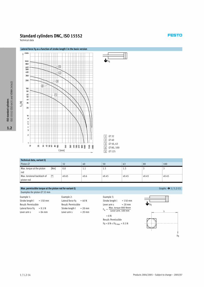
Lateral force Fq as a function of stroke length l in the basic version
l [mm]
F Q [N
]
Fq
1 ∅ 32
2 ∅ 40
3 ∅ 50, 63
4 ∅ 80, 100
5 ∅ 125
Technical data, variant Q
Piston ∅ 32 40 50 63 80 100
Max. torque at the piston
rod
[Nm] 0.8 1.1 1.5 1.5 3 3
Max. torsional backlash of
piston rod
[°] ±0.65 ±0.6 ±0.45 ±0.45 ±0.45 ±0.45
Max. permissible torque at the piston rod for variant Q Graphs � 1 / 1.2−15
Examples for piston ∅ 32 mm
Example 1:
Stroke length l = 150 mm
Result: Permissible
Lateral force Fq = 9.5 N
Lever arm s = 84 mm
Example 2:
Lateral force Fq = 40 N
Result: Permissible
Stroke length l = 28 mm
Lever arm s = 20 mm
Example 3:
Stroke length l = 150 mm
Lever arm s = 20 mm
Fq �Max.�torque�800�Nmm
Lever�arm.�100�mm
= 8 N
Result: Permissible
Fq = 8 N < Fq max. = 9.5 N
Fq
Fq
s
ISO
sta
ndar
d cy
linde
rs
ISO
15
55
2 (I
SO
64
31
and
VD
MA
24
56
2)
1.2

2005/07 – Subject to change – Products 2004/2005 1 / 1.2−15
Standard cylinders DNC, ISO 15552Technical data
Lateral force Fq as a function of the stroke length l and lever arm s in variant Q
Piston ∅ 32 mm Piston ∅ 40 mm
Max. torque = 800 Nmm
Max. stroke = 300 mm
Max. torque = 1,100 Nmm
Max. stroke = 400 mm
Fq [N
]
s [m
m]
l [mm] l [mm]
Fq [N
]
s [m
m]
Piston ∅ 50, 63 mm Piston ∅ 80, 100 mm
Max. torque = 1,500 Nmm
Max. stroke = 500 mm
Max. torque = 3,000 Nmm
Max. stroke = 600 mm
Fq [N
]
s [m
m]
l [mm]
Fq [N
]
s [m
m]
l [mm]
ISO
sta
ndar
d cy
linde
rs
ISO
15
55
2 (I
SO
64
31
and
VD
MA
24
56
2)
1.2

Products 2004/2005 – Subject to change – 2005/071 / 1.2−16
Standard cylinders DNC, ISO 15552Technical data
Weights [g]
Piston ∅ 32 40 50 63 80 100 125
Basic version
Product weight at 0 mm stroke 517 800 1,260 1,709 2,790 4,653 6,771
Additional weight per 10 mm stroke 30 45 64 73 106 115 168
Moving load at 0 mm stroke 162 307 538 663 1,131 1,544 2,809
Additional load per 10 mm stroke 9 16 25 25 38 38 63
Variant K10 – Aluminium piston rod
Product weight at 0 mm stroke 443 655 1,001 1,437 2,302 4,138 5,719
Additional weight per 10 mm stroke 24 35 47 57 81 90 127
Moving load at 0 mm stroke 88 162 279 391 643 1,029 1,757
Additional load per 10 mm stroke 3 6 8 9 13 13 22
Variant Q – Square piston rod
Product weight at 0 mm stroke 504 738 1,187 1,632 2,652 4,508 –
Additional weight per 10 mm stroke 29 41 60 68 99 108 –
Moving load at 0 mm stroke 149 244 465 587 994 1,399 –
Additional load per 10 mm stroke 8 11 20 20 31 31 –
Variant S2 – Through piston rod
Product weight at 0 mm stroke 576 895 1,390 1,917 3,114 5,297 7,529
Additional weight per 10 mm stroke 39 61 89 98 144 153 231
Moving load at 0 mm stroke 170 330 560 711 1,200 1,660 2,925
Additional load per 10 mm stroke 18 32 50 50 76 76 126
Variant S2 – Through piston rod, Variant K10 – Aluminium piston rod
Product weight at 0 mm stroke 514 766 1,181 1,676 2,701 4,821 6,674
Additional weight per 10 mm stroke 27 40 56 65 94 103 148
Moving load at 0 mm stroke 108 201 351 470 787 1,184 2,070
Additional load per 10 mm stroke 6 11 17 17 26 26 43
ISO
sta
ndar
d cy
linde
rs
ISO
15
55
2 (I
SO
64
31
and
VD
MA
24
56
2)
1.2

2005/07 – Subject to change – Products 2004/2005 1 / 1.2−17
Standard cylinders DNC, ISO 15552Technical data
Materials
Sectional view
12 23
Variant Basic version CT K10 R3
1 Cylinder barrel Wrought aluminium alloy,
smooth−anodised
Wrought aluminium alloy,
anodised
Wrought aluminium alloy,
smooth−anodised
Wrought aluminium alloy,
smooth−anodised
2 Bearing and end cap Die−cast aluminium Die−cast aluminium Die−cast aluminium Die−cast aluminium
3 Piston rod High−alloy steel High−alloy steel Wrought aluminium alloy,
anodised
High−alloy stainless steel
– Seals Polyurethane, nitrile rubber Polyurethane, nitrile rubber Polyurethane, nitrile rubber Polyurethane, nitrile rubber
Variant R8 S6 S10 S11
1 Cylinder barrel Wrought aluminium alloy,
smooth−anodised
Wrought aluminium alloy,
smooth−anodised
Wrought aluminium alloy,
smooth−anodised
Wrought aluminium alloy,
smooth−anodised
2 Bearing and end cap Die−cast aluminium Die−cast aluminium Die−cast aluminium Die−cast aluminium
3 Piston rod Tempered steel High−alloy steel High−alloy steel High−alloy steel
– Seals Polyurethane, nitrile rubber Fluorocarbon rubber Fluorocarbon rubber Fluorocarbon rubber
ISO
sta
ndar
d cy
linde
rs
ISO
15
55
2 (I
SO
64
31
and
VD
MA
24
56
2)
1.2

Products 2004/2005 – Subject to change – 2005/071 / 1.2−18
Standard cylinders DNC, ISO 15552Technical data
Dimensions – Basic cylinders Download CAD data � www.festo.com/en/engineering
1 Socket head screw with female
thread for mounting
attachments
2 Regulating screw for adjustable
end−position cushioning
3 Sensor slot for proximity
sensor SME/SMT−8
+ = plus stroke length
∅
[mm]
AM B
∅d11
BG E EE J2 J3 KK L1 L2
32 22 30 16 45 Gx 6 5.2 M10x1.25 18 94
40 24 35 16 54 G¼ 8 6 M12x1.25 21.5 105
50 32 40 17 64 G¼ 10.4 8.5 M16x1.5 28 106
63 32 45 17 75 Gy 12.4 10 M16x1.5 28.5 121
80 40 45 17 93 Gy 12.5 8 M20x1.5 34.7 128
100 40 55 17 110 G½ 12 10 M20x1.5 38.2 138
125 54 60 22 134 G½ 13 8 M27x2 46 160
∅
[mm]
L7 MM
∅PL RT TG VA VD WH ZJ ß1 ß2 ß3
32 3.3 12 15.6 M6 32.5 4 10 26 120 10 16 6
40 3.6 16 14 M6 38 4 10.5 30 135 13 18 6
50 5.1 20 14 M8 46.5 4 11.5 37 143 17 24 8
63 6.6 20 17 M8 56.5 4 15 37 158 17 24 8
80 10.5 25 16.4 M10 72 4 15.7 46 174 22 30 6
100 8 25 18.8 M10 89 4 19.2 51 189 22 30 6
125 14 32 18 M12 110 6 20.5 65 225 27 36 8
ISO
sta
ndar
d cy
linde
rs
ISO
15
55
2 (I
SO
64
31
and
VD
MA
24
56
2)
1.2

2005/07 – Subject to change – Products 2004/2005 1 / 1.2−19
Standard cylinders DNC, ISO 15552Technical data
Dimensions – Variants Download CAD data � www.festo.com/en/engineering
Q – Square piston rod
S2 – Through piston rod
+ = plus stroke length
++ = plus 2 stroke lengths
−H− Note
The thread designs on both piston
rod ends are identical. In combina-
tion with variant Q, the front piston
rod is square, the rear piston rod
round.
S20 – Through, hollow piston rod
+ = plus stroke length
++ = plus 2 stroke lengths
−H− Note
The max. stroke length for all piston
∅ is 850 mm.
In combination with variant K8, the
piston rod is extended on one side
at the bearing cap.
∅ B1
�
D8
∅ZJ ZM
[mm]
32 10 4.5 120 148
40 12 5.5 135 167
50 16 81) 143 183
63 16 8 158 199
80 20 11.7 174 222
100 20 11.7 189 240
125 – 13 225 291
1) Internal narrowing to ∅ 5.5 mm
ISO
sta
ndar
d cy
linde
rs
ISO
15
55
2 (I
SO
64
31
and
VD
MA
24
56
2)
1.2

Products 2004/2005 – Subject to change – 2005/071 / 1.2−20
Standard cylinders DNC, ISO 15552Technical data
Dimensions – Variants Download CAD data � www.festo.com/en/engineering
K2 – Extended male piston rod thread K3 – Female piston rod thread
K5 – Special piston rod thread K7 – Piston rod with external hexagon
K8 – Extended piston rod
−H− Note
In combination with variant S2, the
piston rod is extended on one side
at the bearing cap. If variant Q is
also required, the extension will be
added to the square piston rod. In
combination with variant S20, the
piston rod is extended on both
sides.
∅ A1 A2 AF AM KF KK T4 WH ß1
[mm]
max. max. Basic thread Special
thread1)
32 35 500 12 22 M6 M10x1.25 M10 2.6 26 10
40 35 500 12 24 M8 M12x1.25 M12 3.3 30 13
50 70 500 16 32 M10 M16x1.5 M16 4.7 37 17
63 70 500 16 32 M10 M16x1.5 M16 4.7 37 17
80 70 500 20 40 M12 M20x1.5 M20 6.1 46 22
100 70 500 20 40 M12 M20x1.5 M20 6.1 51 22
125 70 500 32 54 M16 M27x2 M27 8 65 27
1) The special threads are only available as male threads. The scope of delivery does not include a hex nut for the piston rod thread.
ISO
sta
ndar
d cy
linde
rs
ISO
15
55
2 (I
SO
64
31
and
VD
MA
24
56
2)
1.2

2005/07 – Subject to change – Products 2004/2005 1 / 1.2−21
Standard cylinders DNC, ISO 15552Technical data
Ordering data – Basic version
Type Piston ∅ Stroke Without position sensing With position sensing
[mm] [mm] Part No. Type1) Part No. Type1)
32 25 163 319 DNC−32−25−PPV 163 305 DNC−32−25−PPV−A3
40 163 320 DNC−32−40−PPV 163 306 DNC−32−40−PPV−A
50 163 321 DNC−32−50−PPV 163 307 DNC−32−50−PPV−A
80 163 322 DNC−32−80−PPV 163 308 DNC−32−80−PPV−A
100 163 323 DNC−32−100−PPV 163 309 DNC−32−100−PPV−A
125 163 324 DNC−32−125−PPV 163 310 DNC−32−125−PPV−A
160 163 325 DNC−32−160−PPV 163 311 DNC−32−160−PPV−A
200 163 326 DNC−32−200−PPV 163 312 DNC−32−200−PPV−A
250 163 327 DNC−32−250−PPV 163 313 DNC−32−250−PPV−A
320 163 328 DNC−32−320−PPV 163 314 DNC−32−320−PPV−A
400 163 329 DNC−32−400−PPV 163 315 DNC−32−400−PPV−A
500 163 330 DNC−32−500−PPV 163 316 DNC−32−500−PPV−A
40 25 163 351 DNC−40−25−PPV 163 337 DNC−40−25−PPV−A
40 163 352 DNC−40−40−PPV 163 338 DNC−40−40−PPV−A
50 163 353 DNC−40−50−PPV 163 339 DNC−40−50−PPV−A
80 163 354 DNC−40−80−PPV 163 340 DNC−40−80−PPV−A
100 163 355 DNC−40−100−PPV 163 341 DNC−40−100−PPV−A
125 163 356 DNC−40−125−PPV 163 342 DNC−40−125−PPV−A
160 163 357 DNC−40−160−PPV 163 343 DNC−40−160−PPV−A
200 163 358 DNC−40−200−PPV 163 344 DNC−40−200−PPV−A
250 163 359 DNC−40−250−PPV 163 345 DNC−40−250−PPV−A
320 163 360 DNC−40−320−PPV 163 346 DNC−40−320−PPV−A
400 163 361 DNC−40−400−PPV 163 347 DNC−40−400−PPV−A
500 163 362 DNC−40−500−PPV 163 348 DNC−40−500−PPV−A
50 25 163 383 DNC−50−25−PPV 163 369 DNC−50−25−PPV−A5
40 163 384 DNC−50−40−PPV 163 370 DNC−50−40−PPV−A
50 163 385 DNC−50−50−PPV 163 371 DNC−50−50−PPV−A
80 163 386 DNC−50−80−PPV 163 372 DNC−50−80−PPV−A
100 163 387 DNC−50−100−PPV 163 373 DNC−50−100−PPV−A
125 163 388 DNC−50−125−PPV 163 374 DNC−50−125−PPV−A
160 163 389 DNC−50−160−PPV 163 375 DNC−50−160−PPV−A
200 163 390 DNC−50−200−PPV 163 376 DNC−50−200−PPV−A
250 163 391 DNC−50−250−PPV 163 377 DNC−50−250−PPV−A
320 163 392 DNC−50−320−PPV 163 378 DNC−50−320−PPV−A
400 163 393 DNC−50−400−PPV 163 379 DNC−50−400−PPV−A
500 163 394 DNC−50−500−PPV 163 380 DNC−50−500−PPV−A
63 25 163 415 DNC−63−25−PPV 163 401 DNC−63−25−PPV−A3
40 163 416 DNC−63−40−PPV 163 402 DNC−63−40−PPV−A
50 163 417 DNC−63−50−PPV 163 403 DNC−63−50−PPV−A
80 163 418 DNC−63−80−PPV 163 404 DNC−63−80−PPV−A
100 163 419 DNC−63−100−PPV 163 405 DNC−63−100−PPV−A
125 163 420 DNC−63−125−PPV 163 406 DNC−63−125−PPV−A
160 163 421 DNC−63−160−PPV 163 407 DNC−63−160−PPV−A
200 163 422 DNC−63−200−PPV 163 408 DNC−63−200−PPV−A
250 163 423 DNC−63−250−PPV 163 409 DNC−63−250−PPV−A
320 163 424 DNC−63−320−PPV 163 410 DNC−63−320−PPV−A
400 163 425 DNC−63−400−PPV 163 411 DNC−63−400−PPV−A
500 163 426 DNC−63−500−PPV 163 412 DNC−63−500−PPV−A
1) Mounting nut on the piston rod thread included in the scope of delivery.
ISO
sta
ndar
d cy
linde
rs
ISO
15
55
2 (I
SO
64
31
and
VD
MA
24
56
2)
1.2
Core Range

Products 2004/2005 – Subject to change – 2005/071 / 1.2−22
Standard cylinders DNC, ISO 15552Technical data
Ordering data – Basic version
Type Piston ∅ Stroke Without position sensing With position sensing
[mm] [mm] Part No. Type1) Part No. Type1)
80 25 163 447 DNC−80−25−PPV 163 433 DNC−80−25−PPV−A
40 163 448 DNC−80−40−PPV 163 434 DNC−80−40−PPV−A
50 163 449 DNC−80−50−PPV 163 435 DNC−80−50−PPV−A
80 163 450 DNC−80−80−PPV 163 436 DNC−80−80−PPV−A
100 163 451 DNC−80−100−PPV 163 437 DNC−80−100−PPV−A
125 163 452 DNC−80−125−PPV 163 438 DNC−80−125−PPV−A
160 163 453 DNC−80−160−PPV 163 439 DNC−80−160−PPV−A
200 163 454 DNC−80−200−PPV 163 440 DNC−80−200−PPV−A
250 163 455 DNC−80−250−PPV 163 441 DNC−80−250−PPV−A
320 163 456 DNC−80−320−PPV 163 442 DNC−80−320−PPV−A
400 163 457 DNC−80−400−PPV 163 443 DNC−80−400−PPV−A
500 163 458 DNC−80−500−PPV 163 444 DNC−80−500−PPV−A
100 25 163 479 DNC−100−25−PPV 163 465 DNC−100−25−PPV−A
40 163 480 DNC−100−40−PPV 163 466 DNC−100−40−PPV−A
50 163 481 DNC−100−50−PPV 163 467 DNC−100−50−PPV−A
80 163 482 DNC−100−80−PPV 163 468 DNC−100−80−PPV−A
100 163 483 DNC−100−100−PPV 163 469 DNC−100−100−PPV−A
125 163 484 DNC−100−125−PPV 163 470 DNC−100−125−PPV−A
160 163 485 DNC−100−160−PPV 163 471 DNC−100−160−PPV−A
200 163 486 DNC−100−200−PPV 163 472 DNC−100−200−PPV−A
250 163 487 DNC−100−250−PPV 163 473 DNC−100−250−PPV−A
320 163 488 DNC−100−320−PPV 163 474 DNC−100−320−PPV−A
400 163 489 DNC−100−400−PPV 163 475 DNC−100−400−PPV−A
500 163 490 DNC−100−500−PPV 163 476 DNC−100−500−PPV−A
125 25 163 511 DNC−125−25−PPV 163 497 DNC−125−25−PPV−A5
40 163 512 DNC−125−40−PPV 163 498 DNC−125−40−PPV−A
50 163 513 DNC−125−50−PPV 163 499 DNC−125−50−PPV−A
80 163 514 DNC−125−80−PPV 163 500 DNC−125−80−PPV−A
100 163 515 DNC−125−100−PPV 163 501 DNC−125−100−PPV−A
125 163 516 DNC−125−125−PPV 163 502 DNC−125−125−PPV−A
160 163 517 DNC−125−160−PPV 163 503 DNC−125−160−PPV−A
200 163 518 DNC−125−200−PPV 163 504 DNC−125−200−PPV−A
250 163 519 DNC−125−250−PPV 163 505 DNC−125−250−PPV−A
320 163 520 DNC−125−320−PPV 163 506 DNC−125−320−PPV−A
400 163 521 DNC−125−400−PPV 163 507 DNC−125−400−PPV−A
500 163 522 DNC−125−500−PPV 163 508 DNC−125−500−PPV−A
Ordering data – Variants
Type Piston ∅ Stroke Without position sensing With position sensing
[mm] [mm] Part No. Type1) Part No. Type1)
Variable stroke
32 10 Ī 2000 163 318 DNC−32−Ī−PPV 163 304 DNC−32−Ī−PPV−A
40 10 Ī 2000 163 350 DNC−40−Ī−PPV 163 336 DNC−40−Ī−PPV−A
50 10 Ī 2000 163 382 DNC−50−Ī−PPV 163 368 DNC−50−Ī−PPV−A
63 10 Ī 2000 163 414 DNC−63−Ī−PPV 163 400 DNC−63−Ī−PPV−A
80 10 Ī 2000 163 446 DNC−80−Ī−PPV 163 432 DNC−80−Ī−PPV−A
100 10 Ī 2000 163 478 DNC−100−Ī−PPV 163 464 DNC−100−Ī−PPV−A
125 10 Ī 2000 163 510 DNC−125−Ī−PPV 163 496 DNC−125−Ī−PPV−A
1) Mounting nut on the piston rod thread included in the scope of delivery.
ISO
sta
ndar
d cy
linde
rs
ISO
15
55
2 (I
SO
64
31
and
VD
MA
24
56
2)
1.2
Core Range

2005/07 – Subject to change – Products 2004/2005 1 / 1.2−23
Standard cylinders DNC, ISO 15552Ordering data – Modular products
Mandatory data0M Options0O �
Module No. Function Piston
�
Stroke Cushion-
ing
Position
sensing
Protec-
tion
against
torsion
Type of
piston
rod
Male
thread
ex-
tended
Female
thread
Special
thread
163 302
163 334
163 366
163 398
163 430
163 462
163 494
DNC 32
40
50
63
80
100
125
10 Ī 2000 P
PPV
A Q S2
S20
ĪK2 K3 ĪK5
Ordering
example
163 430 DNC – 80 – 550 – PPV – A – Q – S2 – – K3 –
Ordering table
Size 32 40 50 63 80 100 125 Condi-
tions
Code Enter
code
0M Module No. 163 302 163 334 163 366 163 398 163 430 163 462 163 494
Function Standard cylinder, double−acting, based on ISO 15552 DNC DNC
Piston ∅ [mm] 32 40 50 63 80 100 125 −Ī
Stroke [mm] 10 Ī 2000 −Ī
Cushioning Flexible cushioning rings/plates at both ends 1 −Pg
Pneumatic cushioning adjustable at both ends 2 −PPV
0O Position sensing For proximity sensors −A
Protection against torsion Square piston rod – 3 −Q
Type of piston rod Through piston rod 4 −S2yp p
Through, hollow piston rod 5 −S20
Male thread extended Piston rod with extended male thread
[mm] 1 Ī 35 1 Ī 70 6 −ĪK2
Female thread Female piston rod thread
(M6) (M8) (M10) (M10) (M12) (M12) (M16) 7 −K3
Special thread Special piston rod thread
� M10 M12 M16 M16 M20 M20 M27 8 −ĪK5
1 P Not with CT.
2 PPV Not with S10, S11.
3 Q Max. stroke: 10 Ī 1,500 mm
In combination with S2: Square piston rod at bearing cap end only.
Not with S20, K7, K10, S10, S11, CT, R8.
4 S2 In combination with K2: Thread extension on both ends.
In combination with K3: Female thread on both ends.
In combination with K5: Special thread on both ends.
In combination with K8: Piston rod extended at bearing cap end only.
Not with S20, K7, S10, S11.
5 S20 Max. stroke: 850 mm.
In combination with K8: Piston rod extended on both ends.
Not with K2, K3, K5, K10, S10, S11, R8.
6 K2 Not with K3, K10.
7 K3 With K5: On request.
Not with K7.
8 K5 Not with K10.
Transfer order code
DNC – – – – – – – – –
ISO
sta
ndar
d cy
linde
rs
ISO
15
55
2 (I
SO
64
31
and
VD
MA
24
56
2)
1.2

Products 2004/2005 – Subject to change – 2005/071 / 1.2−24
Standard cylinders DNC, ISO 15552Ordering data – Modular products
� Options0O
Special
spanner
flats
Piston rod
extended
Improved
runnin per-
formance
Tempera-
ture
resistant
Constant
motion (at
low speed)
Running
characteris-
tics
Special-
materials
Corrosion
protection
Wiper seal
K7 ĪK8 K10 S6 S10 S11 CT R3 R8
– – 100K8 – – – – – – –
Ordering table
Size 32 40 50 63 80 100 125 Condi-
tions
Code Enter
code
� Special spanner flats Piston rod with external hexagon 9 −K7
0O Piston rod extended Extended piston rod
[mm] 1 Ī 500 −ĪK8
Improved running performance Smooth anodised aluminium coated piston rod – aJ −K10
Temperature−resistant Heat−resistant seals up to max. 150 °C aA −S6
Constant motion (at low speed) Slow speed (constant motion at low piston speeds) – aB −S10
Running characteristics Low friction aC −S11
Special materials Free of copper, PTFE and silicone aD −CT
Corrosion protection High corrosion protection aD −R3
Wiper seal Dust protection −R8
9 K7 Not with Q, S2, K10.
aJ K10 Max. stroke: 1,000 mm.
Not with R3, R8.
aA S6 Not with S10, S11, CT, R8.
aB S10 Max. stroke: 500 mm; further strokes on request.
Not with S11, CT, R3, R8.
aC S11 Max. stroke: 500 mm; further strokes on request.
Not with CT, R3, R8.
aD CT, R3 Not with R8.
Transfer order code
– – – – – – – – –
ISO
sta
ndar
d cy
linde
rs
ISO
15
55
2 (I
SO
64
31
and
VD
MA
24
56
2)
1.2
2005/07 – Subject to change – Products 2004/2005 1 / 1.2−25
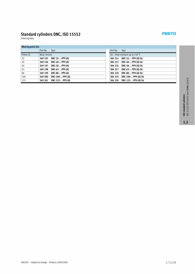
Standard cylinders DNC, ISO 15552Ordering data
Wearing parts kits
Part No. Type Part No. Type
Piston ∅ Basic version S6 – Heat resistant up to 150 °C
32 369 195 DNC−32−Ī−PPV−(A) 384 214 DNC−32−Ī−PPV−(A)−S6
40 369 196 DNC−40−Ī−PPV−(A) 384 215 DNC−40−Ī−PPV−(A)−S6
50 369 197 DNC−50−Ī−PPV−(A) 384 216 DNC−50−Ī−PPV−(A)−S6
63 369 198 DNC−63−Ī−PPV−(A) 384 217 DNC−63−Ī−PPV−(A)−S6
80 369 199 DNC−80−Ī−PPV−(A) 384 218 DNC−80−Ī−PPV−(A)−S6
100 369 200 DNC−100−Ī−PPV−(A) 384 219 DNC−100−Ī−PPV−(A)−S6
125 369 201 DNC−125−Ī−PPV−(A) 384 220 DNC−125−Ī−PPV−(A)−S6
ISO
sta
ndar
d cy
linde
rs
ISO
15
55
2 (I
SO
64
31
and
VD
MA
24
56
2)
1.2

Products 2004/2005 – Subject to change – 2005/071 / 1.2−26
Standard cylinder DNC−KP, clamping cartridge for piston rodTechnical data
Function
DNC−Ī
without position sensing
DNC−Ī−A−Ī
with positio se si
−N− Diameter
32 Ī 125 mm
−T− Stroke length
10 Ī 2,000 mm
−W− www.festo.com/en/
KP
with position sensingW www.festo.com/en/
Spare_parts_serviceSpare_parts_service
Wearing parts kits
� 1 / 1.2−35
Conforms to
� ISO 15552
� ISO 6431
� VDMA 24562
�NFE 49003.1
�UNI 10290
DIN
General technical data
Piston ∅ 32 40 50 63 80 100 125
Stroke [mm] Basic version 10 Ī 2,000 [ ]
Q 10 Ī 1,500 10 Ī 1,500 10 Ī 1,500 10 Ī 1,500 10 Ī 1,500 10 Ī 1,500 –
Pneumatic Cylinder Gx G¼ G¼ Gy Gy G½ G½
connection Clamping
cartridge
M5 Gx Gx Gx Gx Gx Gx
Piston rod thread Basic version M10x1.25 M12x1.25 M16x1.5 M16x1.5 M20x1.5 M20x1.5 M27x2
K3 M6 M8 M10 M10 M12 M12 M16
K5 M10 M12 M16 M16 M20 M20 M27
Constructional design Pistong
Piston rod
Cylinder barrel
Clamping cartridge
Cushioning P Non−adjustable at either end
Cushioning PPV Adjustable at both ends
Cushioning length
PPV
[mm] 20 20 22 22 32 32 42
Position sensing With proximity sensor
Type of mounting Via female threadyp g
Via accessories
Assembly position Any
Operating and environmental conditions
Piston ∅ 32 40 50 63 80 100 125
Operating medium Filtered compressed air, lubricated or unlubricated
Operating pressure [bar] 1.5 Ī 10
Min. release pressure [bar] 3
Ambient temperature1) [°C] –10 Ī +80
Corrosion resistance class CRC2) 2
1) Note operating range of proximity sensors.
2) Corrosion resistance class 2 according to Festo standard 940 070
Components requiring moderate corrosion resistance. Externally visible parts with primarily decorative surface requirements which are in direct contact with a normal industrial environment or media such as coolants
or lubricating agents.
ISO
sta
ndar
d cy
linde
rs
ISO
15
55
2 (I
SO
64
31
and
VD
MA
24
56
2)
1.2
2005/07 – Subject to change – Products 2004/2005 1 / 1.2−27
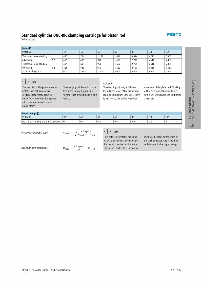
Standard cylinder DNC−KP, clamping cartridge for piston rodTechnical data
Forces [N]
Piston ∅ 32 40 50 63 80 100 125
Theoretical force at 6 bar, 483 754 1,178 1,870 3,016 4,712 7,363 ,
advancing S2 415 633 990 1,682 2,721 4,418 6,881
Theoretical force at 6 bar, 415 633 990 1,682 2,721 4,418 6,881 ,
retracting S2 415 633 990 1,682 2,721 4,418 6,881
Static holding force 600 1,000 1,400 2,000 5,000 5,000 7,500
−H− NoteActivation
The specified holding force refers to
a static load. If this value is ex-
ceeded, slippage may occur. Dy-
namic forces occurring during oper-
ation must not exceed the static
holding force.
The clamping unit is not backlash−
free in the clamped condition if
varying loads are applied to the pis-
ton rod.
The clamping unit may only be re-
leased if the forces at the piston have
reached equilibrium. Otherwise, there
is a risk of accidents due to sudden
movement of the piston rod. Blocking
off the sir supply at both ends (e.g.
with a 5/3−way valve) does not provide
any safety.
Impact energy [J]
Piston ∅ 32 40 50 63 80 100 125
Max. impact energy at the end positions 0.1 0.2 0.2 0.5 0.9 1.2 5
vperm.� �2�x�Eperm.
mdead� �� mload
�
mload� �2�x�Eperm.
v2���mdeadMaximum permissible load:
Permissible impact velocity: −H− Note
This data represents the maximum
values that can be achieved. Values
fluctuate in practice relative to the
size of the effective load. Allowance
must also be made for the limits of
the cushioning capacity of the drive
and the permissible impact energy.
ISO
sta
ndar
d cy
linde
rs
ISO
15
55
2 (I
SO
64
31
and
VD
MA
24
56
2)
1.2

Products 2004/2005 – Subject to change – 2005/071 / 1.2−28
Standard cylinder DNC−KP, clamping cartridge for piston rodTechnical data
Axial backlash at the piston rod [mm]
Piston ∅ 32 40 50 63 80 100 125
Max. axial backlash at the clamped
piston rod
0.25 0.25 0.30 0.30 0.30 0.30 0.30
Lateral force Fq as a function of stroke length l
l [mm]
Fq [N
]
Fq
1 ∅ 32
2 ∅ 40
3 ∅ 50, 63
4 ∅ 80, 100
5 ∅ 125
ISO
sta
ndar
d cy
linde
rs
ISO
15
55
2 (I
SO
64
31
and
VD
MA
24
56
2)
1.2
2005/07 – Subject to change – Products 2004/2005 1 / 1.2−29
Standard cylinder DNC−KP, clamping cartridge for piston rodTechnical data
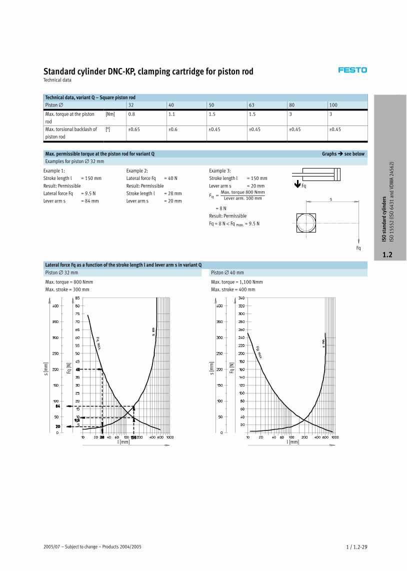
Technical data, variant Q – Square piston rod
Piston ∅ 32 40 50 63 80 100
Max. torque at the piston
rod
[Nm] 0.8 1.1 1.5 1.5 3 3
Max. torsional backlash of
piston rod
[°] ±0.65 ±0.6 ±0.45 ±0.45 ±0.45 ±0.45
Max. permissible torque at the piston rod for variant Q Graphs � see below
Examples for piston ∅ 32 mm
Example 1:
Stroke length l = 150 mm
Result: Permissible
Lateral force Fq = 9.5 N
Lever arm s = 84 mm
Example 2:
Lateral force Fq = 40 N
Result: Permissible
Stroke length l = 28 mm
Lever arm s = 20 mm
Example 3:
Stroke length l = 150 mm
Lever arm s = 20 mm
Fq �Max.�torque�800�Nmm
Lever�arm.�100�mm
= 8 N
Result: Permissible
Fq = 8 N < Fq max. = 9.5 N
Fq
Fq
s
Lateral force Fq as a function of the stroke length l and lever arm s in variant Q
Piston ∅ 32 mm Piston ∅ 40 mm
Max. torque = 800 Nmm
Max. stroke = 300 mm
Max. torque = 1,100 Nmm
Max. stroke = 400 mm
Fq [N
]
s [m
m]
l [mm] l [mm]
Fq [N
]
s [m
m]
ISO
sta
ndar
d cy
linde
rs
ISO
15
55
2 (I
SO
64
31
and
VD
MA
24
56
2)
1.2

Products 2004/2005 – Subject to change – 2005/071 / 1.2−30
Standard cylinder DNC−KP, clamping cartridge for piston rodTechnical data
Piston ∅ 50, 63 mm Piston ∅ 80, 100 mm
Max. torque = 1,500 Nmm
Max. stroke = 500 mm
Max. torque = 3,000 Nmm
Max. stroke = 600 mm
Fq [N
]
s [m
m]
l [mm]
Fq [N
]
s [m
m]
l [mm]
Materials
Sectional view
12 23
4
7
65
Cylinder with clamping cartridge
1 Cylinder barrel Wrought aluminium alloy, smooth−anodised
2 Bearing and end cap Die−cast aluminium
3 Piston rod High−alloy steel
4 Housing Wrought aluminium alloy, anodised
5 Clamping jaws Brass
6 Spring Spring steel
7 Piston Polyacetal
– Seals Polyurethane, nitrile rubber
ISO
sta
ndar
d cy
linde
rs
ISO
15
55
2 (I
SO
64
31
and
VD
MA
24
56
2)
1.2

2005/07 – Subject to change – Products 2004/2005 1 / 1.2−31
Standard cylinder DNC−KP, clamping cartridge for piston rodTechnical data
Dimensions – Basic cylinders Download CAD data � www.festo.com/en/engineering
1 Socket head screw with female
thread for mounting
attachments
2 Regulating screw for adjustable
end−position cushioning
3 Sensor slot for proximity
sensor SME/SMT−8
+ = plus stroke length
∅
[mm]
AM B
∅d11
BG D1
∅f9
D2 E EE H1 J2 J3 KK L2 L3
32 22 30 16 20 M5 45 Gx 67 6 5.2 M10x1.25 94 45
40 24 35 16 24 Gx 54 G¼ 88 8 6 M12x1.25 105 53
50 32 40 17 30 Gx 64 G¼ 107 10.4 8.5 M16x1.5 106 67
63 32 45 17 38 Gx 75 Gy 123 12.4 10 M16x1.5 121 76
80 40 45 17 48 Gx 93 Gy 165.5 12.5 8 M20x1.5 128 95
100 40 55 17 48 Gx 110 G½ 174 12 10 M20x1.5 138 98
125 54 60 22 65 Gx 134 G½ 207 13 8 M27x2 160 125
∅
[mm]
L5 L7 MM
∅PL RT TG VA VD WH ZJ ß1 ß2 ß3
32 14 3.3 12 15.6 M6 32.5 4 11.5 26 165 10 16 6
40 16 3.6 16 14 M6 38 4 11.5 30 188 13 18 6
50 20 5.1 20 14 M8 46.5 4 11 37 210 17 24 8
63 24 6.6 20 17 M8 56.5 4 11 37 234 17 24 8
80 31.5 10.5 25 16.4 M10 72 4 12.5 46 269 22 30 6
100 31 8 25 18.8 M10 89 4 12 51 287 22 30 6
125 42 14 32 18 M12 110 6 27.5 65 350 27 36 8
−H− Note
The dimensions for the cylinder/
valve combination are on page
� 1 / 1.2−48
ISO
sta
ndar
d cy
linde
rs
ISO
15
55
2 (I
SO
64
31
and
VD
MA
24
56
2)
1.2

Products 2004/2005 – Subject to change – 2005/071 / 1.2−32
Standard cylinder DNC−KP, clamping cartridge for piston rodTechnical data
Dimensions – Variants Download CAD data � www.festo.com/en/engineering
Q – Square piston rod
S2 – Through piston rod
+ = plus stroke length
++ = plus 2 stroke lengths
The thread designs on both piston rod
ends are identical. The clamping car-
tridge is mounted on only one side.
In combination with variant Q, the
front piston rod is square, the rear
piston rod round. The clamping
cartridge is mounted on the rear,
round piston rod.
K2 – Extended male piston rod thread K3 – Female piston rod thread
K5 – Special piston rod thread K7 – Piston rod with external hexagon
K8 – Extended piston rod
In combination with variant S2, the
piston rod is extended on one side at
the bearing cap. The clamping unit is
mounted on the side of the piston rod
that is not extended. If variant Q is
also required, the extension will only
be added to the square piston rod.
∅ A1 A2 AF AM B1 KF KK T4 WH ZJ ZM ß1
[mm]
max. max. � Basic
thread
Special
thread1)
32 35 500 12 22 10 M6 M10x1.25 M10 2.6 26 165 193 10
40 35 500 12 24 12 M8 M12x1.25 M12 3.3 30 188 220 13
50 70 500 16 32 16 M10 M16x1.5 M16 4.7 37 210 250 17
63 70 500 16 32 16 M10 M16x1.5 M16 4.7 37 234 275 17
80 70 500 20 40 20 M12 M20x1.5 M20 6.1 46 269 317 22
100 70 500 20 40 20 M12 M20x1.5 M20 6.1 51 287 338 22
125 70 500 32 54 – M16 M27x2 M27 8 65 350 416 27
1) The special threads are only available as male threads. The scope of delivery does not include a hex nut for the piston rod thread.
ISO
sta
ndar
d cy
linde
rs
ISO
15
55
2 (I
SO
64
31
and
VD
MA
24
56
2)
1.2

2005/07 – Subject to change – Products 2004/2005 1 / 1.2−33
Standard cylinder DNC−KP, clamping cartridge for piston rodOrdering data – Modular products
Mandatory data0M Options0O �
Module No. Drive function Piston � Stroke Cushioning Position
sensing
Protection
against torsion
Type of piston
rod
163 302
163 334
163 366
163 398
163 430
163 462
163 494
DNC 32
40
50
63
80
100
125
10 Ī 2000 P
PPV
A Q S2
Ordering
example
163 430 DNC – 80 – 550 – PPV – A – Q – S2
Ordering table
Size 32 40 50 63 80 100 125 Condi-
tions
Code Enter
code
0M Module No. 163 302 163 334 163 366 163 398 163 430 163 462 163 494
Drive function Double−acting cylinder based on ISO 15552 DNC DNC
Piston ∅ [mm] 32 40 50 63 80 100 125 −Ī
Stroke [mm] 10 Ī 2000 −Ī
Cushioning Flexible cushioning rings/plates at both ends −Pg
Pneumatic cushioning adjustable at both ends −PPV
0O Position sensing For proximity sensors −A
Protection against torsion Square piston rod – 1 −Q
� Type of piston rod Through piston rod 2 −S2
1 Q Max. stroke: 10 Ī 1,500 mm
In combination with S2: Square piston rod at bearing cap end only.
In combination with KP: Only supplied with S2.
Not with K7.
2 S2 In combination with K2: Thread extension on both ends.
In combination with K3: Female thread on both ends.
In combination with K5: Special thread on both ends.
In combination with K8: Piston rod extended at bearing cap end only.
In combination with KP: Clamping cartridge on the end cap.
Not with K7.
Transfer order code
DNC – – – – – –
ISO
sta
ndar
d cy
linde
rs
ISO
15
55
2 (I
SO
64
31
and
VD
MA
24
56
2)
1.2
Products 2004/2005 – Subject to change – 2005/071 / 1.2−34
Standard cylinder DNC−KP, clamping cartridge for piston rodOrdering data – Modular products
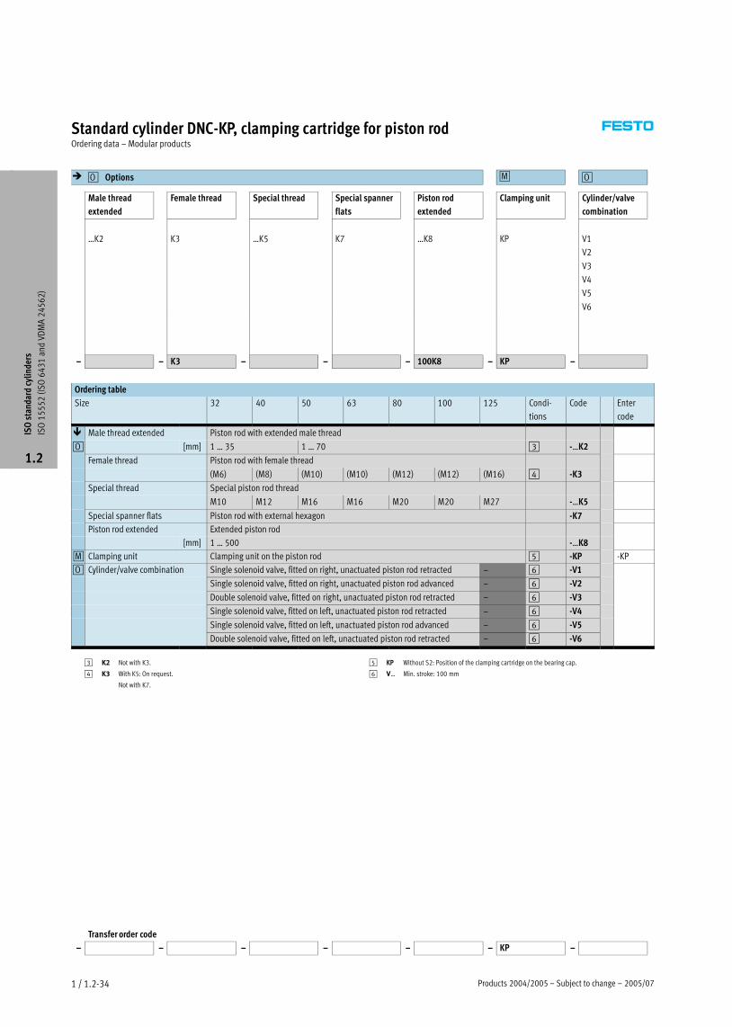
� Options0O 0M 0O
Male thread
extended
Female thread Special thread Special spanner
flats
Piston rod
extended
Clamping unit Cylinder/valve
combination
ĪK2 K3 ĪK5 K7 ĪK8 KP V1
V2
V3
V4
V5
V6
– – K3 – – – 100K8 – KP –
Ordering table
Size 32 40 50 63 80 100 125 Condi-
tions
Code Enter
code
� Male thread extended Piston rod with extended male thread
0O [mm] 1 Ī 35 1 Ī 70 3 −ĪK2
Female thread Piston rod with female thread
(M6) (M8) (M10) (M10) (M12) (M12) (M16) 4 −K3
Special thread Special piston rod threadp
M10 M12 M16 M16 M20 M20 M27 −ĪK5
Special spanner flats Piston rod with external hexagon −K7
Piston rod extended Extended piston rod
[mm] 1 Ī 500 −ĪK8
0M Clamping unit Clamping unit on the piston rod 5 −KP −KP
0O Cylinder/valve combination Single solenoid valve, fitted on right, unactuated piston rod retracted – 6 −V1y /
Single solenoid valve, fitted on right, unactuated piston rod advanced – 6 −V2
Double solenoid valve, fitted on right, unactuated piston rod retracted – 6 −V3
Single solenoid valve, fitted on left, unactuated piston rod retracted – 6 −V4
Single solenoid valve, fitted on left, unactuated piston rod advanced – 6 −V5
Double solenoid valve, fitted on left, unactuated piston rod retracted – 6 −V6
3 K2 Not with K3.
4 K3 With K5: On request.
Not with K7.
5 KP Without S2: Position of the clamping cartridge on the bearing cap.
6 VĪ Min. stroke: 100 mm
Transfer order code
– – – – – – KP –
ISO
sta
ndar
d cy
linde
rs
ISO
15
55
2 (I
SO
64
31
and
VD
MA
24
56
2)
1.2

2005/07 – Subject to change – Products 2004/2005 1 / 1.2−35
Standard cylinder DNC−KP, clamping cartridge for piston rodOrdering data
Wearing parts kits
Part No. Type
Piston ∅ Basic version
32 369 195 DNC−32−Ī−PPV−(A)
40 369 196 DNC−40−Ī−PPV−(A)
50 369 197 DNC−50−Ī−PPV−(A)
63 369 198 DNC−63−Ī−PPV−(A)
80 369 199 DNC−80−Ī−PPV−(A)
100 369 200 DNC−100−Ī−PPV−(A)
125 369 201 DNC−125−Ī−PPV−(A)
ISO
sta
ndar
d cy
linde
rs
ISO
15
55
2 (I
SO
64
31
and
VD
MA
24
56
2)
1.2

Products 2004/2005 – Subject to change – 2005/071 / 1.2−36
Standard cylinder DNC−EL, with end position lockTechnical data
Function
DNC−Ī−A−Ī−EL
with position sensing
−N− Diameter
32 Ī 100 mm
−T− Stroke length
10 2 000 mm
EL
−W− www.festo.com/en/
Spare_parts_service
Wearing parts kits
� 1 / 1.2−25
10 Ī 2,000 mm
Conforms to
� ISO 15552
� ISO 6431
� VDMA 24562
�NFE 49003.1
�UNI 10290
DIN
General technical data
Piston ∅ 32 40 50 63 80 100
Stroke [mm] Basic version 10 Ī 2000
Pneumatic Basic version Gx G¼ G¼ Gy Gy G½
connection EL M3 M5
Piston rod thread M10x1.25 M12x1.25 M16x1.5 M16x1.5 M20x1.5 M20x1.5
Constructional design Pistong
Piston rod
Cylinder barrel
End position lock ELV Advanced end positionp
ELH Retracted end position
ELB Both end positions
Cushioning P Non−adjustable at either end
Cushioning PPV Adjustable at both ends
Cushioning length Basic version 20 20 22 22 32 32g g
PPV [mm] EL 8.2 8.3 7.3 10.8 9.8 11.8
Position sensing With proximity sensor
Type of mounting Via female threadyp g
Via accessories
Assembly position Any
−H− Note
� The end position lock should only
be operated in conjunction with
double−acting exhaust−air
restricted cylinders, in order to
ensure that the lock is always com-
pletely released prior to starting the
drive movement.
�No screws with a head or similar
may be used in place of the end
position lock, as there is a risk that
the function will be impaired if they
are screwed in too deeply.
� The end position locking is to be
used as a piston rod safety device
in the event of pressure failure.
� Locking can be performed from any
stroke position, once the drive is
brought mechanically into its end
position.
� The exhaust hole must not be
closed.
� If the end position cushioning is set
too high (more than 50% closed),
the locking screw may not engage
securely and therefore be subject to
premature wear.
ISO
sta
ndar
d cy
linde
rs
ISO
15
55
2 (I
SO
64
31
and
VD
MA
24
56
2)
1.2

2005/07 – Subject to change – Products 2004/2005 1 / 1.2−37
Standard cylinder DNC−EL, with end position lockTechnical data
Operating and environmental conditions
Piston ∅ 32 40 50 63 80 100
Operating medium Filtered compressed air, lubricated or unlubricated
Operating pressure [bar] 1.5 Ī 12
Min. release pressure [bar] ≤ 1.5
Ambient temperature1) [°C] –20 Ī +80
Corrosion resistance class CRC2) 2
1) Note operating range of proximity sensors.
2) Corrosion resistance class 2 according to Festo standard 940 070
Components requiring moderate corrosion resistance. Externally visible parts with primarily decorative surface requirements which are in direct contact with a normal industrial environment or media such as coolants
or lubricating agents.
Forces [N] and impact energy [J]
Piston ∅ 32 40 50 63 80 100
Theoretical force at 6 bar,
advancing
Basic
version
483 754 1,178 1,870 3,016 4,712
Theoretical force at 6 bar,
retracting
Basic
version
415 633 990 1,682 2,721 4,418
Static holding force1) −EL 500 2000 5000
Max. impact energy at the end positions 0.1 0.2 0.2 0.5 0.9 1.2
1) Not more than 50% of the theoretical cylinder force.
vperm.� �2�x�Eperm.
mdead� �� mload
�
mload� �2�x�Eperm.
v2���mdeadMaximum permissible load:
Permissible impact velocity: −H− Note
This data represents the maximum
values that can be achieved. Values
fluctuate in practice relative to the
size of the effective load. Allowance
must also be made for the limits of
the cushioning capacity of the drive
and the permissible impact energy.
Axial backlash at the piston rod [mm]
Piston ∅ 32 40 50 63 80 100
Max. axial backlash at locked end lock ≤ 1.3 ≤ 2.1
ISO
sta
ndar
d cy
linde
rs
ISO
15
55
2 (I
SO
64
31
and
VD
MA
24
56
2)
1.2

Products 2004/2005 – Subject to change – 2005/071 / 1.2−38
Standard cylinder DNC−EL, with end position lockTechnical data
Lateral force Fq as a function of stroke length l
F Q [N
]
l [mm]
1 ∅ 32
2 ∅ 40
3 ∅ 50, 63
4 ∅ 80, 100
Fq
Weights [g]
Piston ∅ 32 40 50 63 80 100
Product weight 20 60 180
Moving load, end lock piston 3 14 41
Materials
Sectional view
12 23
Cylinder with clamping cartridge
1 Cylinder barrel Wrought aluminium alloy, smooth−anodised
2 Bearing and end cap Die−cast aluminium
3 Piston rod High−alloy steel
– Seals Polyurethane, nitrile rubber
ISO
sta
ndar
d cy
linde
rs
ISO
15
55
2 (I
SO
64
31
and
VD
MA
24
56
2)
1.2
2005/07 – Subject to change – Products 2004/2005 1 / 1.2−39
Standard cylinder DNC−EL, with end position lockTechnical data
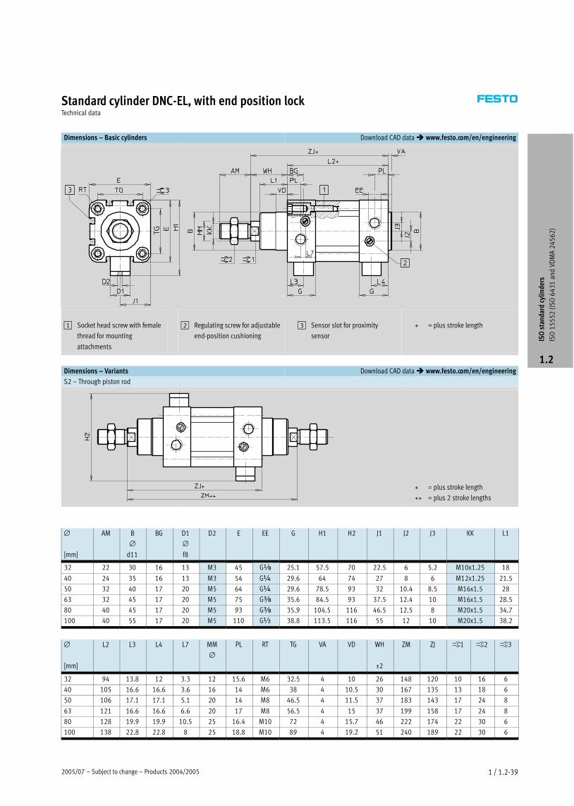
Dimensions – Basic cylinders Download CAD data � www.festo.com/en/engineering
1 Socket head screw with female
thread for mounting
attachments
2 Regulating screw for adjustable
end−position cushioning
3 Sensor slot for proximity
sensor
+ = plus stroke length
Dimensions – Variants Download CAD data � www.festo.com/en/engineering
S2 – Through piston rod
+ = plus stroke length
++ = plus 2 stroke lengths
∅
[mm]
AM B
∅d11
BG D1
∅f8
D2 E EE G H1 H2 J1 J2 J3 KK L1
1
32 22 30 16 13 M3 45 Gx 25.1 57.5 70 22.5 6 5.2 M10x1.25 18
40 24 35 16 13 M3 54 G¼ 29.6 64 74 27 8 6 M12x1.25 21.5
50 32 40 17 20 M5 64 G¼ 29.6 78.5 93 32 10.4 8.5 M16x1.5 28
63 32 45 17 20 M5 75 Gy 35.6 84.5 93 37.5 12.4 10 M16x1.5 28.5
80 40 45 17 20 M5 93 Gy 35.9 104.5 116 46.5 12.5 8 M20x1.5 34.7
100 40 55 17 20 M5 110 G½ 38.8 113.5 116 55 12 10 M20x1.5 38.2
∅
[mm]
L2 L3 L4 L7 MM
∅PL RT TG VA VD WH
±2
ZM ZJ ß1 ß2 ß3
32 94 13.8 12 3.3 12 15.6 M6 32.5 4 10 26 148 120 10 16 6
40 105 16.6 16.6 3.6 16 14 M6 38 4 10.5 30 167 135 13 18 6
50 106 17.1 17.1 5.1 20 14 M8 46.5 4 11.5 37 183 143 17 24 8
63 121 16.6 16.6 6.6 20 17 M8 56.5 4 15 37 199 158 17 24 8
80 128 19.9 19.9 10.5 25 16.4 M10 72 4 15.7 46 222 174 22 30 6
100 138 22.8 22.8 8 25 18.8 M10 89 4 19.2 51 240 189 22 30 6
ISO
sta
ndar
d cy
linde
rs
ISO
15
55
2 (I
SO
64
31
and
VD
MA
24
56
2)
1.2

Products 2004/2005 – Subject to change – 2005/071 / 1.2−40
Standard cylinder DNC−EL, with end position lockTechnical data
Dimensions – Variants Download CAD data � www.festo.com/en/engineering
K2 – Extended male piston rod thread
K3 – Female piston rod thread
K5 – Special piston rod thread
K8 – Extended piston rod
−H− Note
In combination with variant S2, the
piston rod is extended on one side
at the bearing cap.
∅ A1 A2 AF AM KF KK T4 WH ß1
[mm]
max. max. Basic thread Special
thread1)
32 35 500 12 22 M6 M10x1.25 M10 2.6 26 10
40 35 500 12 24 M8 M12x1.25 M12 3.3 30 13
50 70 500 16 32 M10 M16x1.5 M16 4.7 37 17
63 70 500 16 32 M10 M16x1.5 M16 4.7 37 17
80 70 500 20 40 M12 M20x1.5 M20 6.1 46 22
100 70 500 20 40 M12 M20x1.5 M20 6.1 51 22
1) The special threads are only available as male threads. The scope of delivery does not include a hex nut for the piston rod thread.
ISO
sta
ndar
d cy
linde
rs
ISO
15
55
2 (I
SO
64
31
and
VD
MA
24
56
2)
1.2

Products 2004/2005 – Subject to change – 2005/071 / 1.2−42
Standard cylinder DNC−EL, with end position lockOrdering data – Modular products
Mandatory data0M Options0O �
Module No. Function Piston � Stroke Cushioning Position sensing Type of piston rod
163 302
163 334
163 366
163 398
163 430
163 462
DNC 32
40
50
63
80
100
10 Ī 2000 P
PPV
A S2
Ordering
example
163 430 DNC – 80 – 550 – PPV – A – S2
Ordering table
Size 32 40 50 63 80 100 Condi-
tions
Code Enter
code
0M Module No. 163 302 163 334 163 366 163 398 163 430 163 462
Function Standard cylinder, double−acting, based on ISO 15552 DNC DNC
Piston ∅ [mm] 32 40 50 63 80 100 −Ī
Stroke [mm] 10 Ī 2000 −Ī
Cushioning Flexible cushioning rings/plates at both ends −Pg
Pneumatic cushioning adjustable at both ends −PPV
0O Position sensing For proximity sensors −A
� Type of piston rod Through piston rod 1 −S2
1 S2 In combination with K2: Thread extension on both ends.
In combination with K3: Female thread on both ends.
In combination with K5: Special thread on both ends.
Transfer order code
DNC – – – – –
ISO
sta
ndar
d cy
linde
rs
ISO
15
55
2 (I
SO
64
31
and
VD
MA
24
56
2)
1.2

2005/07 – Subject to change – Products 2004/2005 1 / 1.2−43
Standard cylinder DNC−EL, with end position lockOrdering data – Modular products
� Options0O 0M
Male thread extended Female thread Special thread Piston rod extended End lock
ĪK2 K3 ĪK5 ĪK8 ELB
ELV
ELH
– – K3 – – 100K8 –
Ordering table
Size 32 40 50 63 80 100 Condi-
tions
Code Enter
code
� Male thread extended Piston rod with extended male thread
0O [mm] 1 Ī 35 1 Ī 70 2 −ĪK2
Female thread Female piston rod thread
(M6) (M8) (M10) (M10) (M12) (M12) 3 −K3
Special thread Special piston rod thread
M10 M12 M16 M16 M20 M20 −ĪK5
Piston rod extended Extended piston rod
[mm] 1 Ī 500 −ĪK8
0M End lock End position lock on both sides 4 −ELB
End position lock, front 4 −ELV
End position lock, rear 4 −ELH
2 K2 Not with K3.
3 K3 With K5: On request.
4 ELB, ELV, ELH In combination with K8 and S2: On request.
Transfer order code
– – – – –
ISO
sta
ndar
d cy
linde
rs
ISO
15
55
2 (I
SO
64
31
and
VD
MA
24
56
2)
1.2
Products 2004/2005 – Subject to change – 2005/071 / 1.2−44
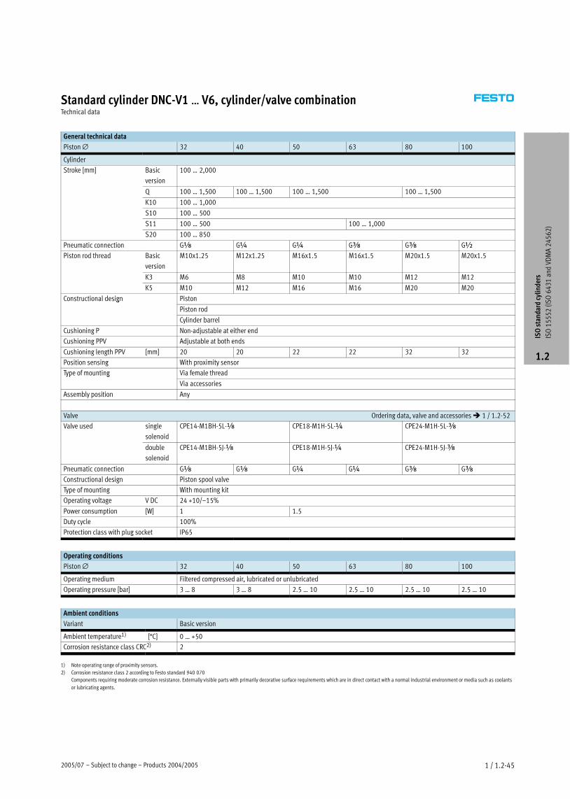
Standard cylinder DNC−V1 Ī V6, cylinder/valve combinationTechnical data
Function
DNC−Ī
without position sensing
DNC−Ī−A−Ī
with positio se si
−N− Diameter
32 Ī 100 mm
−T− Stroke length
100 Ī 2,000 mm
−W− www.festo.com/en/
Spare_parts_service
Wearing parts kitswith position sensing
Wearing parts kits
� 1 / 1.2−35� 1 / 1.2−35Conforms to
� ISO 15552
� ISO 6431
� VDMA 24562
�NFE 49003.1
�UNI 10290
DIN
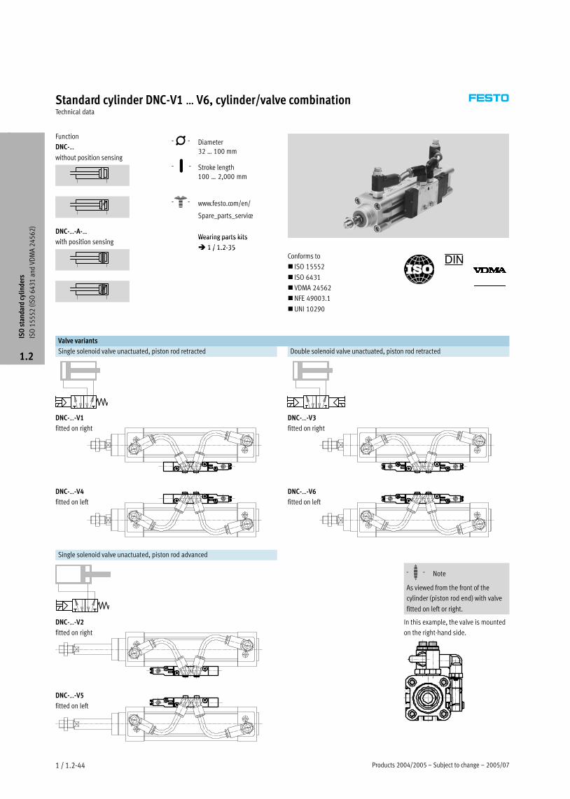
Valve variants
Single solenoid valve unactuated, piston rod retracted Double solenoid valve unactuated, piston rod retracted
DNC−Ī−V1
fitted on right
DNC−Ī−V3
fitted on right
DNC−Ī−V4
fitted on left
DNC−Ī−V6
fitted on left
Single solenoid valve unactuated, piston rod advanced
−H− Note
As viewed from the front of the
cylinder (piston rod end) with valve
fitted on left or right.
DNC−Ī−V2
fitted on right
In this example, the valve is mounted
on the right−hand side.
DNC−Ī−V5
fitted on left
ISO
sta
ndar
d cy
linde
rs
ISO
15
55
2 (I
SO
64
31
and
VD
MA
24
56
2)
1.2
2005/07 – Subject to change – Products 2004/2005 1 / 1.2−45
Standard cylinder DNC−V1 Ī V6, cylinder/valve combinationTechnical data
General technical data
Piston ∅ 32 40 50 63 80 100
Cylinder
Stroke [mm] Basic
version
100 Ī 2,000
Q 100 Ī 1,500 100 Ī 1,500 100 Ī 1,500 100 Ī 1,500
K10 100 Ī 1,000
S10 100 Ī 500
S11 100 Ī 500 100 Ī 1,000
S20 100 Ī 850
Pneumatic connection Gx G¼ G¼ Gy Gy G½
Piston rod thread Basic
version
M10x1.25 M12x1.25 M16x1.5 M16x1.5 M20x1.5 M20x1.5
K3 M6 M8 M10 M10 M12 M12
K5 M10 M12 M16 M16 M20 M20
Constructional design Pistong
Piston rod
Cylinder barrel
Cushioning P Non−adjustable at either end
Cushioning PPV Adjustable at both ends
Cushioning length PPV [mm] 20 20 22 22 32 32
Position sensing With proximity sensor
Type of mounting Via female threadyp g
Via accessories
Assembly position Any
Valve Ordering data, valve and accessories � 1 / 1.2−52
Valve used single
solenoid
CPE14−M1BH−5L−x CPE18−M1H−5L−¼ CPE24−M1H−5L−y
double
solenoid
CPE14−M1BH−5J−x CPE18−M1H−5J−¼ CPE24−M1H−5J−y
Pneumatic connection Gx Gx G¼ G¼ Gy Gy
Constructional design Piston spool valve
Type of mounting With mounting kit
Operating voltage V DC 24 +10/–15%
Power consumption [W] 1 1.5
Duty cycle 100%
Protection class with plug socket IP65
Operating conditions
Piston ∅ 32 40 50 63 80 100
Operating medium Filtered compressed air, lubricated or unlubricated
Operating pressure [bar] 3 Ī 8 3 Ī 8 2.5 Ī 10 2.5 Ī 10 2.5 Ī 10 2.5 Ī 10
Ambient conditions
Variant Basic version
Ambient temperature1) [°C] 0 Ī +50
Corrosion resistance class CRC2) 2
1) Note operating range of proximity sensors.
2) Corrosion resistance class 2 according to Festo standard 940 070
Components requiring moderate corrosion resistance. Externally visible parts with primarily decorative surface requirements which are in direct contact with a normal industrial environment or media such as coolants
or lubricating agents.
ISO
sta
ndar
d cy
linde
rs
ISO
15
55
2 (I
SO
64
31
and
VD
MA
24
56
2)
1.2

Products 2004/2005 – Subject to change – 2005/071 / 1.2−46
Standard cylinder DNC−V1 Ī V6, cylinder/valve combinationTechnical data
Forces [N] and impact energy [J]
Piston ∅ 32 40 50 63 80 100
Theoretical force at 6 bar, 483 754 1,178 1,870 3,016 4,712 ,
advancing S2/S20 415 633 990 1,682 2,721 4,418
Theoretical force at 6 bar, 415 633 990 1,682 2,721 4,418 ,
retracting S2/S20 415 633 990 1,682 2,721 4,418
Max. impact energy at the end
positions1)
0.1 0.2 0.2 0.5 0.9 1.2
1) The permitted impact energy is reduced by approx. 10% for variants K10 and S20.
vperm.� �2�x�Eperm.
mdead� �� mload
�
mload� �2�x�Eperm.
v2���mdeadMaximum permissible load:
Permissible impact velocity: −H− Note
This data represents the maximum
values that can be achieved. Values
fluctuate in practice relative to the
size of the effective load. Allowance
must also be made for the limits of
the cushioning capacity of the drive
and the permissible impact energy.
Lateral force Fq as a function of stroke length l in the basic version
l [mm]
Fq [N
]
Fq
1 ∅ 32
2 ∅ 40
3 ∅ 50, 63
4 ∅ 80, 100
ISO
sta
ndar
d cy
linde
rs
ISO
15
55
2 (I
SO
64
31
and
VD
MA
24
56
2)
1.2

2005/07 – Subject to change – Products 2004/2005 1 / 1.2−47
Standard cylinder DNC−V1 Ī V6, cylinder/valve combinationTechnical data
Technical data, variant Q
Piston ∅ 32 40 50 63 80 100
Max. torque at the piston
rod
[Nm] 0.8 1.1 1.5 1.5 3 3
Max. torsional backlash of
piston rod
[°] ±0.65 ±0.6 ±0.45 ±0.45 ±0.45 ±0.45
Max. permissible torque at the piston rod for variant Q Graphs � 1 / 1.2−15
Examples for piston ∅ 32 mm
Example 1:
Stroke length l = 150 mm
Result: Permissible
Lateral force Fq = 9.5 N
Lever arm s = 84 mm
Example 2:
Lateral force Fq = 40 N
Result: Permissible
Stroke length l = 28 mm
Lever arm s = 20 mm
Example 3:
Stroke length l = 150 mm
Lever arm s = 20 mm
Fq �Max.�torque�800�Nmm
Lever�arm.�100�mm
= 8 N
Result: Permissible
Fq = 8 N < Fq max. = 9.5 N
Fq
Fq
s
Materials
Sectional view
1 22
34
Variant Basic version R8 S10 S11 K10
1 Cylinder barrel Wrought aluminium
alloy, smooth−
anodised
Wrought aluminium
alloy, smooth−
anodised
Wrought aluminium
alloy, smooth−
anodised
Wrought aluminium
alloy, smooth−
anodised
Wrought aluminium
alloy, smooth−
anodised
2 Bearing and end cap Die−cast aluminium Die−cast aluminium Die−cast aluminium Die−cast aluminium Die−cast aluminium
3 Piston rod High−alloy steel Tempered steel High−alloy steel High−alloy steel Wrought aluminium
alloy, anodised
– Seals, cylinder Polyurethane, nitrile
rubber
Polyurethane, nitrile
rubber
Fluorocarbon rubber Fluorocarbon rubber Polyurethane, nitrile
rubber
4 Housing, valve Die−cast aluminium, polyamide, steel
– Seals, valve Nitrile rubber
ISO
sta
ndar
d cy
linde
rs
ISO
15
55
2 (I
SO
64
31
and
VD
MA
24
56
2)
1.2

Products 2004/2005 – Subject to change – 2005/071 / 1.2−48
Standard cylinder DNC−V1 Ī V6, cylinder/valve combinationTechnical data
Dimensions Download CAD data � www.festo.com/en/engineering
1 Plug socket not included in
scope of delivery
+½ = plus half stroke length
ISO
sta
ndar
d cy
linde
rs
ISO
15
55
2 (I
SO
64
31
and
VD
MA
24
56
2)
1.2

2005/07 – Subject to change – Products 2004/2005 1 / 1.2−49
Standard cylinder DNC−V1 Ī V6, cylinder/valve combinationTechnical data
∅
[mm]
B1 B2 E1 H1 H2 L1
max.
L2
±3
L3 L4 L5 ß1 ß2
32 62 59 Gx 109+5.5 86+5.5 152 22 102 118 13 13 14
40 71 68 Gx 114+5.5 94+5.5 152 23 102 118 13 17 14
50 85 82 G¼ 131+5.5 104+5.5 215 24 138 163 25 17 14
63 96 93 G¼ 142+5.5 115+5.5 215 25 138 163 25 19 14
80 123 119 Gy 194+5.5 133+5.5 242 28 165 165 25 19 17
100 140 136 Gy 213+2 158+2 242 30 165 165 25 27 17
−H− Note
Further dimensions relating to the
basic cylinder and its variants are
provided on page � 1 / 1.2−18,
with clamping cartridge on page
� 1 / 1.2−31.
ISO
sta
ndar
d cy
linde
rs
ISO
15
55
2 (I
SO
64
31
and
VD
MA
24
56
2)
1.2

Products 2004/2005 – Subject to change – 2005/071 / 1.2−50
Standard cylinder DNC−V1 Ī V6, cylinder/valve combinationOrdering data – Modular products
Mandatory data0M Options0O �
Module No. Drive function Piston � Stroke Cushioning Position
sensing
Protection
against torsion
Type of piston
rod
163 302
163 334
163 366
163 398
163 430
163 462
DNC 32
40
50
63
80
100
100 Ī 2000 P
PPV
A Q S2
S20
Ordering
example
163 430 DNC – 80 – 550 – PPV – A – Q – S2
Ordering table
Size 32 40 50 63 80 100 Condi-
tions
Code Enter
code
0M Module No. 163 302 163 334 163 366 163 398 163 430 163 462
Drive function Double−acting cylinder based on ISO 15552 DNC DNC
Piston ∅ [mm] 32 40 50 63 80 100 −Ī
Stroke [mm] 100 Ī 2000 −Ī
Cushioning Flexible cushioning rings/plates at both ends −Pg
Pneumatic cushioning adjustable at both ends 1 −PPV
0O Position sensing For proximity sensors −A
Protection against torsion Square piston rod 2 −Q
Type of piston rod Through piston rod 3 −S2yp p
Through, hollow piston rod 4 −S20
1 PPV Not with S10, S11.
2 Q Max. stroke: 100 Ī 1,500 mm
In combination with S2: Square piston rod at bearing cap end only.
In combination with KP: Only supplied with S2.
Not with S20, K7, K10, S10, S11.
3 S2 In combination with K2: Thread extension on both ends.
In combination with K3: Female thread on both ends.
In combination with K5: Special thread on both ends.
In combination with K8: Piston rod extended at bearing cap end only.
In combination with KP: Clamping cartridge on the end cap.
Not with S20, K7, S10, S11.
4 S20 Max. stroke: 850 mm.
In combination with K8: Piston rod extended on both ends.
Not with K2, K3, K5, K10, KP, S10, S11.
Transfer order code
DNC – – – – – –
ISO
sta
ndar
d cy
linde
rs
ISO
15
55
2 (I
SO
64
31
and
VD
MA
24
56
2)
1.2

2005/07 – Subject to change – Products 2004/2005 1 / 1.2−51
Standard cylinder DNC−V1 Ī V6, cylinder/valve combinationOrdering data – Modular products
� Options0O 0M
Male
thread
extended
Female
thread
Special
thread
Special
spanner
flats
Piston rod
extended
Improved
running
perform-
ance
Clamping
unit
Slow
speed
Low
friction
Cylinder/valve
combination
ĪK2 K3 ĪK5 K7 ĪK8 K10 KP S10 S11 V1
V2
V3
V4
V5
V6
– – – – – 100K8 – – – – – V2
Ordering table
Size 32 40 50 63 80 100 Condi-
tions
Code Enter
code
� Male thread extended Male thread extended
0O [mm] 1 Ī 35 1 Ī 70 5 −ĪK2
Female thread Piston rod with female thread
(M6) (M8) (M10) (M10) (M12) (M12) 6 −K3
Special thread Special piston rod threadp
M10 M12 M16 M16 M20 M20 7 −ĪK5
Special spanner flats Piston rod with external hexagon 8 −K7
Piston rod extended Extended piston rod
[mm] 1 Ī 500 −ĪK8
Improved running performance Smooth anodised aluminium coated piston rod 9 −K10
Clamping unit Clamping unit on the piston rod aJ −KP
Slow speed Slow speed (constant motion at low piston speeds) aA −S10
Low friction Low friction aB −S11
0M Cylinder/valve combination Single solenoid valve, fitted on right, unactuated piston rod retracted −V1y /
Single solenoid valve, fitted on right, unactuated piston rod advanced −V2
Double solenoid valve, fitted on right, unactuated piston rod retracted −V3
Single solenoid valve, fitted on left, unactuated piston rod retracted −V4
Single solenoid valve, fitted on left, unactuated piston rod advanced −V5
Double solenoid valve, fitted on left, unactuated piston rod retracted −V6
5 K2 Not with K3, K10.
6 K3 With K5: On request.
Not with K7.
7 K5 Not with K10.
8 K7 Not with Q, S2, K10.
9 K10 Max. stroke: 1000 mm.
Not with KP.
aJ KP Without S2: Position of the clamping cartridge on the bearing cap.
Not with S10, S11.
aA S10 Max. stroke: 500 mm; further strokes on request.
Not with S11.
aB S11 Max. stroke: 500 mm; further strokes on request.
Transfer order code
– – – – – – – – – –
ISO
sta
ndar
d cy
linde
rs
ISO
15
55
2 (I
SO
64
31
and
VD
MA
24
56
2)
1.2

Products 2004/2005 – Subject to change – 2005/041 / 1.2−52
Standard cylinder DNC−V1 Ī V6, cylinder/valve combinationAccessories
Ordering data – Valve Technical data � Volume 2
Ordering data – Valve Technical data � www.festo.com
For ∅ Pneumatic connection Protection class Part No. Type
[mm]
Single solenoid
32 Gx IP65 196 941 CPE14−M1BH−5L−x
40
x 5 9 9 x
50 G¼ IP65 163 142 CPE18−M1H−5L−¼
63
¼ 5 3 ¼
80 Gy IP65 163 166 CPE24−M1H−5L−y
100
y 5 3 y
Double solenoid
32 Gx IP65 196 939 CPE14−M1BH−5J−x
40
x 5 9 939 J x
50 G¼ IP65 163 143 CPE18−M1H−5J−¼
63
¼ 5 3 3 J ¼
80 Gy IP65 163 167 CPE24−M1H−5J−y
100
y 5 3 J y
Ordering data – Valve accessories
For valve Part No. Type PU1)
Push−in/threaded fittings QS Technical data � Volume 3
Push−in/threaded fittings QS Technical data � www.festo.com
CPE14 153 015 QS−x−8−I 10
CPE18 153 018 QS−¼−10−I 10
CPE24 153 020 QS−y−12−I 10
Plug socket KMYZ/KMEB Technical data � Volume 2
Plug socket KMYZ/KMEB Technical data � www.festo.com
CPE14 24 V DC, with PVC cable 0.5 m 185 519 KMYZ−4−24−0.5 –
24 V DC, with PVC cable 2.5 m 185 520 KMYZ−4−24−2,5 –
CPE18 24 V DC, with PVC cable 2.5 m, LED 151 688 KMEB−1−24−2,5−LED –
CPE24 24 V DC, with PVC cable 5 m, LED 151 689 KMEB−1−24−5−LED –
24 V DC, with PVC cable 10 m, LED 193 457 KMEB−1−24−10−LED –
Mounting kit ZVB
CPE14 185 705 ZVB−8−14/18 –
CPE18
/
CPE24 187 388 ZVB−8−24 –
1) Packaging unit quantity
ISO
sta
ndar
d cy
linde
rs
ISO
15
55
2 (I
SO
64
31
and
VD
MA
24
56
2)
1.2
Core Range

2005/04 – Subject to change – Products 2004/2005 1 / 1.2−53
Standard cylinders DNC, ISO 15552Accessories
Adapter kit DPNC
Material:
Flange: Wrought aluminium alloy
Threaded studs, hex nuts: Galvanised
steel
+ = plus stroke length
Dimensions and ordering data
For ∅ F1 ZJ Max.
overall stroke length
Weight Part No. Type
[mm] Basic
cylinder
KP [mm] [g]
−H− Note32 27 120 165 1,000 85 174 418 DPNC−32−H− Note40 27 135 188 1,000 115 174 419 DPNC−40
The maximum overall stroke length 50 32 143 210 1,000 210 174 420 DPNC−50must not be exceeded when combin- 63 28 158 234 1,000 360 174 421 DPNC−63ing cylinders and the adapter kit. 80 38 174 269 1,000 620 174 422 DPNC−80
100 38 189 287 1,000 1,190 174 423 DPNC−100
125 48 225 350 1,000 1,600 174 424 DPNC−125
Connecting two cylinders with identical piston � as a 3 or 4−position cylinder
A 3 or 4−position cylinder consists of
two separate cylinders whose piston
rods advance in opposing directions.
This means that depending upon
actuation and stroke pattern, this type
of cylinder can assume up to four
positions. In each case the cylinder is
driven precisely against a stop. Note
that when one end of the piston rod is
fixed, the cylinder barrel executes the
movement. The cylinder must be con-
nected with flexible line connections.
To achieve 3 positions To achieve 4 positions
Two cylinders with identical stroke
length must be connected together.
Two cylinders with different stroke
lengths must be connected together.
ISO
sta
ndar
d cy
linde
rs
ISO
15
55
2 (I
SO
64
31
and
VD
MA
24
56
2)
1.2

Products 2004/2005 – Subject to change – 2005/041 / 1.2−54
Standard cylinders DNC, ISO 15552Accessories
Foot mounting HNC/CRHNC
Material:
HNC: Galvanised steel
CRHNC: High−alloy steel
Free of copper, PTFE and silicone
+ = plus stroke length
Dimensions and ordering data
For ∅ AB
∅AH AO AT AU SA TR US XA XS
[mm] Basic
cylinder
KP Basic
cylinder
KP
32 7 32 6.5 4 24 142 187 32 45 144 189 45
40 10 36 9 4 28 161 214 36 54 163 216 53
50 10 45 9.5 5 32 170 237 45 64 175 242 62
63 10 50 12.5 5 32 185 261 50 75 190 266 63
80 12 63 15 6 41 210 305 63 93 215 310 81
100 14.5 71 17.5 6 41 220 318 75 110 230 328 86
125 16.5 90 22 8 45 250 375 90 131 270 395 102
For ∅ Basic version High corrosion protection
[mm]
CRC1) Weight
[g]
Part No. Type CRC1) Weight
[g]
Part No. Type
32 2 135 174 369 HNC−32 4 135 176 937 CRHNC−32
40 2 180 174 370 HNC−40 4 180 176 938 CRHNC−40
50 2 325 174 371 HNC−50 4 325 176 939 CRHNC−50
63 2 405 174 372 HNC−63 4 405 176 940 CRHNC−63
80 2 820 174 373 HNC−80 4 820 176 941 CRHNC−80
100 2 1,000 174 374 HNC−100 4 1,000 176 942 CRHNC−100
125 2 1,840 174 375 HNC−125 4 1,840 176 943 CRHNC−125
1) Corrosion resistance class 2 according to Festo standard 940 070
Components requiring moderate corrosion resistance. Externally visible parts with primarily decorative surface requirements which are in direct contact with a normal industrial environment or media such as coolants
or lubricating agents.
Corrosion resistance class 4 according to Festo standard 940 070
Components requiring higher corrosion resistance. Parts used with aggressive media, e.g. food or chemical industry. These applications should be supported with special tests with the media if required.
ISO
sta
ndar
d cy
linde
rs
ISO
15
55
2 (I
SO
64
31
and
VD
MA
24
56
2)
1.2
Core Range

2005/04 – Subject to change – Products 2004/2005 1 / 1.2−55
Standard cylinders DNC, ISO 15552Accessories
Flange mounting FNC/CRFNG
Material:
FNC: Galvanised steel
CRFNG: High−alloy steel
Free of copper, PTFE and silicone
+ = plus stroke length
Dimensions and ordering data
For ∅ E FB
∅MF R TF UF W ZF
[mm] H13 Basic cylinder KP
32 45 7 10 32 64 80 16 130 175
40 54 9 10 36 72 90 20 145 198
50 65 9 12 45 90 110 25 155 222
63 75 9 12 50 100 120 25 170 246
80 93 12 16 63 126 150 30 190 285
100 110 14 16 75 150 175 35 205 303
125 132 16 20 90 180 210 45 245 370
For ∅ Basic version High corrosion protection
[mm]
CRC1) Weight
[g]
Part No. Type CRC1) Weight
[g]
Part No. Type
32 2 240 174 376 FNC−32 4 240 161 846 CRFNG−32
40 2 280 174 377 FNC−40 4 300 161 847 CRFNG−40
50 2 520 174 378 FNC−50 4 550 161 848 CRFNG−50
63 2 690 174 379 FNC−63 4 710 161 849 CRFNG−63
80 2 1,650 174 380 FNC−80 4 1,680 161 850 CRFNG−80
100 2 2,400 174 381 FNC−100 4 2,450 161 851 CRFNG−100
125 2 3,750 174 382 FNC−125 4 3,660 185 363 CRFNG−125
1) Corrosion resistance class 2 according to Festo standard 940 070
Components requiring moderate corrosion resistance. Externally visible parts with primarily decorative surface requirements which are in direct contact with a normal industrial environment or media such as coolants
or lubricating agents.
Corrosion resistance class 4 according to Festo standard 940 070
Components requiring higher corrosion resistance. Parts used with aggressive media, e.g. food or chemical industry. These applications should be supported with special tests with the media if required.IS
O s
tand
ard
cylin
ders
ISO
15
55
2 (I
SO
64
31
and
VD
MA
24
56
2)
1.2
Core Range

Products 2004/2005 – Subject to change – 2005/041 / 1.2−56
Standard cylinders DNC, ISO 15552Accessories
Trunnion flange ZNCF/CRZNG
Material:
ZNCF: Special steel casting
CRZNG: Electrolytically polished
stainless steel casting
Free of copper, PTFE and silicone
+ = plus stroke length
Dimensions and ordering data
For ∅ C2 C3 TD
∅TK TL TM US XH XL
[mm] e9 Basic
cylinder
KP
32 71 86 12 16 12 50 45 18 128 173
40 87 105 16 20 16 63 54 20 145 198
50 99 117 16 24 16 75 64 25 155 222
63 116 136 20 24 20 90 75 25 170 246
80 136 156 20 28 20 110 93 32 188 283
100 164 189 25 38 25 132 110 32 208 306
125 192 217 25 50 25 160 131 40 250 375
For ∅ Basic version High corrosion protection
[mm]
CRC1) Weight
[g]
Part No. Type CRC1) Weight
[g]
Part No. Type
32 2 130 174 411 ZNCF−32 4 150 161 852 CRZNG−32
40 2 240 174 412 ZNCF−40 4 260 161 853 CRZNG−40
50 2 390 174 413 ZNCF−50 4 430 161 854 CRZNG−50
63 2 600 174 414 ZNCF−63 4 640 161 855 CRZNG−63
80 2 1,150 174 415 ZNCF−80 4 1,300 161 856 CRZNG−80
100 2 2,030 174 416 ZNCF−100 4 2,400 161 857 CRZNG−100
125 2 3,490 174 417 ZNCF−125 4 3,600 185 362 CRZNG−125
1) Corrosion resistance class 2 according to Festo standard 940 070
Components requiring moderate corrosion resistance. Externally visible parts with primarily decorative surface requirements which are in direct contact with a normal industrial environment or media such as coolants
or lubricating agents.
Corrosion resistance class 4 according to Festo standard 940 070
Components requiring higher corrosion resistance. Parts used with aggressive media, e.g. food or chemical industry. These applications should be supported with special tests with the media if required.
ISO
sta
ndar
d cy
linde
rs
ISO
15
55
2 (I
SO
64
31
and
VD
MA
24
56
2)
1.2

2005/04 – Subject to change – Products 2004/2005 1 / 1.2−57
Standard cylinders DNC, ISO 15552Accessories
Trunnion mounting kit ZNCM
for basic cylinder DNC
The mounting kit can be attached at
any position along the profile barrel of
a cylinder.
Material:
Tempered steel
+ = plus stroke length
+½ = plus half stroke length1 Max. tightening torque
for DNC−KP
+ = plus stroke length
+½ = plus half stroke length 1 Max. tightening torque
Dimensions and ordering data
For ∅ B1 C2 C3 TD
∅TL TM UW XG
[mm] e9 Basic cylinder KP
32 30 71 86 12 12 50 65 66.1 111.1
40 32 87 105 16 16 63 75 75.6 128.6
50 34 99 117 16 16 75 95 83.6 150.6
63 41 116 136 20 20 90 105 93.1 169.1
80 44 136 156 20 20 110 130 103.9 198.9
100 48 164 189 25 25 132 145 113.8 211.8
125 50 192 217 25 25 160 175 134.7 259.7
For ∅ XJ XV Max.
tightening torque
CRC1) Weight Part No. Type
[mm] Basic cylinder KP Basic cylinder KP [Nm] [g]
32 79.9 124.9 73 118 4+1 2 210 163 525 ZNCM−32
40 89.4 142.4 82.5 135.5 8+1 2 385 163 526 ZNCM−40
50 96.4 163.4 90 157 8+2 2 595 163 527 ZNCM−50
63 101.9 177.9 97.5 173.5 18+2 2 890 163 528 ZNCM−63
80 116.1 211.1 110 205 28+2 2 1,450 163 529 ZNCM−80
100 126.2 224.2 120 218 28+2 2 2,045 163 530 ZNCM−100
125 155.3 280.3 145 270 40+2 2 2,940 163 531 ZNCM−125
1) Corrosion resistance class 2 according to Festo standard 940 070
Components requiring moderate corrosion resistance. Externally visible parts with primarily decorative surface requirements which are in direct contact with a normal industrial environment or media such as coolants
or lubricating agents.
ISO
sta
ndar
d cy
linde
rs
ISO
15
55
2 (I
SO
64
31
and
VD
MA
24
56
2)
1.2
Core Range

Products 2004/2005 – Subject to change – 2005/041 / 1.2−58
Standard cylinders DNC, ISO 15552Accessories
Trunnion support LNZG
Material:
Galvanised steel
Free of copper, PTFE and silicone
Dimensions and ordering data
For ∅ CR
∅DA
∅FK
∅FN FS H1 HB
∅KE NH TH UL CRC1) Weight Part No. Type
[mm] D11 H13 ±0.1 H13 ±0.2 [g]
32 12 11 15 30 10.5 15 6.6 6.8 18 32 46 2 125 32 959 LNZG−32
40, 50 16 15 18 36 12 18 9 9 21 36 55 2 400 32 960 LNZG−40/50
63, 80 20 18 20 40 13 20 11 11 23 42 65 2 480 32 961 LNZG−63/80
100, 125 25 20 25 50 16 24.5 14 13 28.5 50 75 2 960 32 962 LNZG−100/125
1) Corrosion resistance class 2 according to Festo standard 940 070
Components requiring moderate corrosion resistance. Externally visible parts with primarily decorative surface requirements which are in direct contact with a normal industrial environment or media such as coolants
or lubricating agents.
Trunnion support CRLNZG
Material:
High−alloy steel
Free of copper, PTFE and silicone
Dimensions and ordering data
For ∅ CR
∅FK
∅FN FS H1 HB
∅NH TH UL CRC1) Weight Part No. Type
[mm] D11 ±0.1 H13 ±0.2 [g]
32 12 15 30 10.5 15 6.6 18 32 46 4 200 161 874 CRLNZG−32
40, 50 16 18 36 12 18 9 21 36 55 4 330 161 875 CRLNZG−40/50
63, 80 20 20 40 13 20 11 23 42 65 4 440 161 876 CRLNZG−63/80
100, 125 25 25 50 16 24.5 14 28.5 50 75 4 740 161 877 CRLNZG−100
1) Corrosion resistance class 4 according to Festo standard 940 070
Components requiring higher corrosion resistance. Parts used with aggressive media, e.g. food or chemical industry. These applications should be supported with special tests with the media if required.
ISO
sta
ndar
d cy
linde
rs
ISO
15
55
2 (I
SO
64
31
and
VD
MA
24
56
2)
1.2
Core Range
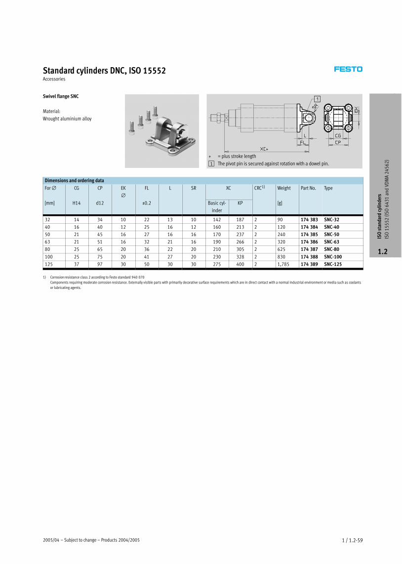
2005/04 – Subject to change – Products 2004/2005 1 / 1.2−59
Standard cylinders DNC, ISO 15552Accessories
Swivel flange SNC
Material:
Wrought aluminium alloy
+ = plus stroke length
1 The pivot pin is secured against rotation with a dowel pin.
Dimensions and ordering data
For ∅ CG CP EK
∅FL L SR XC CRC1) Weight Part No. Type
[mm] H14 d12 ±0.2 Basic cyl-
inder
KP [g]
32 14 34 10 22 13 10 142 187 2 90 174 383 SNC−32
40 16 40 12 25 16 12 160 213 2 120 174 384 SNC−40
50 21 45 16 27 16 16 170 237 2 240 174 385 SNC−50
63 21 51 16 32 21 16 190 266 2 320 174 386 SNC−63
80 25 65 20 36 22 20 210 305 2 625 174 387 SNC−80
100 25 75 20 41 27 20 230 328 2 830 174 388 SNC−100
125 37 97 30 50 30 30 275 400 2 1,785 174 389 SNC−125
1) Corrosion resistance class 2 according to Festo standard 940 070
Components requiring moderate corrosion resistance. Externally visible parts with primarily decorative surface requirements which are in direct contact with a normal industrial environment or media such as coolants
or lubricating agents.
ISO
sta
ndar
d cy
linde
rs
ISO
15
55
2 (I
SO
64
31
and
VD
MA
24
56
2)
1.2
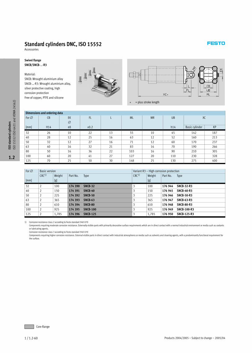
Products 2004/2005 – Subject to change – 2005/041 / 1.2−60
Standard cylinders DNC, ISO 15552Accessories
Swivel flange
SNCB/SNCB−Ī−R3
Material:
SNCB: Wrought aluminium alloy
SNCB−Ī−R3: Wrought aluminium alloy,
silver protective coating, high
corrosion protection
Free of copper, PTFE and silicone
+ = plus stroke length
Dimensions and ordering data
For ∅ CB EK
∅FL L ML MR UB XC
[mm] H14 e8 ±0.2 h14 Basic cylinder KP
32 26 10 22 13 55 10 45 142 187
40 28 12 25 16 63 12 52 160 213
50 32 12 27 16 71 12 60 170 237
63 40 16 32 21 83 16 70 190 266
80 50 16 36 22 103 16 90 210 305
100 60 20 41 27 127 20 110 230 328
125 70 25 50 30 148 25 130 275 400
For ∅ Basic version Variant R3 – High corrosion protection
[mm]
CRC1) Weight
[g]
Part No. Type CRC1) Weight
[g]
Part No. Type
32 2 100 174 390 SNCB−32 3 100 176 944 SNCB−32−R3
40 2 150 174 391 SNCB−40 3 150 176 945 SNCB−40−R3
50 2 225 174 392 SNCB−50 3 225 176 946 SNCB−50−R3
63 2 365 174 393 SNCB−63 3 365 176 947 SNCB−63−R3
80 2 610 174 394 SNCB−80 3 610 176 948 SNCB−80−R3
100 2 925 174 395 SNCB−100 3 925 176 949 SNCB−100−R3
125 2 1,785 174 396 SNCB−125 3 1,785 176 950 SNCB−125−R3
1) Corrosion resistance class 2 according to Festo standard 940 070
Components requiring moderate corrosion resistance. Externally visible parts with primarily decorative surface requirements which are in direct contact with a normal industrial environment or media such as coolants
or lubricating agents.
Corrosion resistance class 3 according to Festo standard 940 070
Components requiring higher corrosion resistance. External visible parts in direct contact with industrial atmospheres or media such as solvents and cleaning agents, with a predominantly functional requirement for
the surface.
ISO
sta
ndar
d cy
linde
rs
ISO
15
55
2 (I
SO
64
31
and
VD
MA
24
56
2)
1.2
Core Range

2005/04 – Subject to change – Products 2004/2005 1 / 1.2−61
Standard cylinders DNC, ISO 15552Accessories
Swivel flange SNCS
Material:
Wrought aluminium alloy
+ = plus stroke length
Dimensions and ordering data
For ∅ CN
∅EP EX FL LT MS XC CRC1) Weight Part No. Type
[mm] –0.2 ±0.2 Basic
cylinder
KP [g]
32 10 10.5 14 22 13 15 142 187 2 85 174 397 SNCS−32
40 12 12 16 25 16 17 160 213 2 125 174 398 SNCS−40
50 16 15 21 27 18 20 170 237 2 210 174 399 SNCS−50
63 16 15 21 32 21 22 190 266 2 280 174 400 SNCS−63
80 20 18 25 36 22 27 210 305 2 540 174 401 SNCS−80
100 20 18 25 41 27 29 230 328 2 700 174 402 SNCS−100
125 30 25 37 50 30 39 275 400 2 1,410 174 403 SNCS−125
1) Corrosion resistance class 2 according to Festo standard 940 070
Components requiring moderate corrosion resistance. Externally visible parts with primarily decorative surface requirements which are in direct contact with a normal industrial environment or media such as coolants
or lubricating agents.
Swivel flange SNCL
Material:
Wrought aluminium alloy
Free of copper, PTFE and silicone
+ = plus stroke length
Dimensions and ordering data
For ∅ CD
∅EW FL L MR XC CRC1) Weight Part No. Type
[mm] h14 ±0.2 Basic
cylinder
KP [g]
32 10 26 22 13 10 142 187 2 75 174 404 SNCL−32
40 12 28 25 16 12 160 213 2 100 174 405 SNCL−40
50 12 32 27 16 12 170 237 2 160 174 406 SNCL−50
63 16 40 32 21 16 190 266 2 250 174 407 SNCL−63
80 16 50 36 22 16 210 305 2 405 174 408 SNCL−80
100 20 60 41 27 20 230 328 2 655 174 409 SNCL−100
125 25 70 50 30 25 275 400 2 1,245 174 410 SNCL−125
1) Corrosion resistance class 2 according to Festo standard 940 070
Components requiring moderate corrosion resistance. Externally visible parts with primarily decorative surface requirements which are in direct contact with a normal industrial environment or media such as coolants
or lubricating agents.
ISO
sta
ndar
d cy
linde
rs
ISO
15
55
2 (I
SO
64
31
and
VD
MA
24
56
2)
1.2
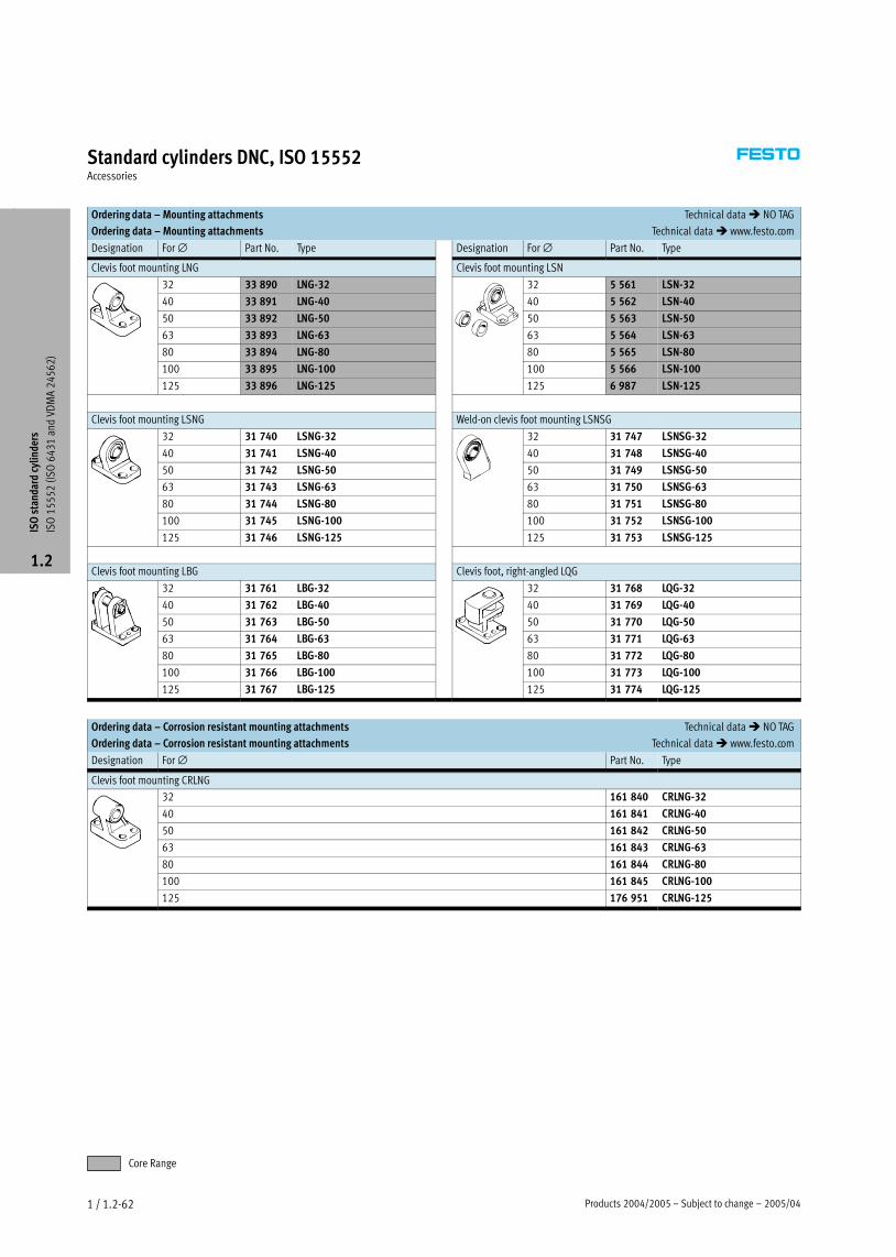
Products 2004/2005 – Subject to change – 2005/041 / 1.2−62
Standard cylinders DNC, ISO 15552Accessories
Ordering data – Mounting attachments Technical data � NO TAG
Ordering data – Mounting attachments Technical data � www.festo.com
Designation For ∅ Part No. Type Designation For ∅ Part No. Type
Clevis foot mounting LNG Clevis foot mounting LSN
32 33 890 LNG−32 32 5 561 LSN−32
40 33 891 LNG−40 40 5 562 LSN−40
50 33 892 LNG−50 50 5 563 LSN−50
63 33 893 LNG−63 63 5 564 LSN−63
80 33 894 LNG−80 80 5 565 LSN−80
100 33 895 LNG−100 100 5 566 LSN−100
125 33 896 LNG−125 125 6 987 LSN−125
Clevis foot mounting LSNG Weld−on clevis foot mounting LSNSG
32 31 740 LSNG−32 32 31 747 LSNSG−32
40 31 741 LSNG−40 40 31 748 LSNSG−40
50 31 742 LSNG−50 50 31 749 LSNSG−50
63 31 743 LSNG−63 63 31 750 LSNSG−63
80 31 744 LSNG−80 80 31 751 LSNSG−80
100 31 745 LSNG−100 100 31 752 LSNSG−100
125 31 746 LSNG−125 125 31 753 LSNSG−125
Clevis foot mounting LBG Clevis foot, right−angled LQG
32 31 761 LBG−32 32 31 768 LQG−32
40 31 762 LBG−40 40 31 769 LQG−40
50 31 763 LBG−50 50 31 770 LQG−50
63 31 764 LBG−63 63 31 771 LQG−63
80 31 765 LBG−80 80 31 772 LQG−80
100 31 766 LBG−100 100 31 773 LQG−100
125 31 767 LBG−125 125 31 774 LQG−125
Ordering data – Corrosion resistant mounting attachments Technical data � NO TAG
Ordering data – Corrosion resistant mounting attachments Technical data � www.festo.com
Designation For ∅ Part No. Type
Clevis foot mounting CRLNG
32 161 840 CRLNG−32
40 161 841 CRLNG−40
50 161 842 CRLNG−50
63 161 843 CRLNG−63
80 161 844 CRLNG−80
100 161 845 CRLNG−100
125 176 951 CRLNG−125
ISO
sta
ndar
d cy
linde
rs
ISO
15
55
2 (I
SO
64
31
and
VD
MA
24
56
2)
1.2
Core Range

2005/04 – Subject to change – Products 2004/2005 1 / 1.2−63
Standard cylinders DNC, ISO 15552Accessories
Ordering data – Piston rod attachments Technical data � NO TAG
Ordering data – Piston rod attachments Technical data � www.festo.com
Designation For ∅ Part No. Type Designation For ∅ Part No. Type
Rod eye SGS Rod clevis SGA
32 9 261 SGS−M10x1,25 32 32 954 SGA−M10x1.25
40 9 262 SGS−M12x1,25 40 10 767 SGA−M12x1,25
50 9 263 SGS−M16x1,5 50 10 768 SGA−M16x1,5
63
9 3 ,
63
,
80 9 264 SGS−M20x1,5 80 10 769 SGA−M20x1,5
100
9 ,
100
9 ,
125 10 774 SGS−M27x2 125 10 770 SGA−M27x2
Rod clevis SG Self−aligning rod coupler FK
32 6 144 SG−M10x1,25 32 6 140 FK−M10x1,25
40 6 145 SG−M12x1,25 40 6 141 FK−M12x1,25
50 6 146 SG−M16x1,5 50 6 142 FK−M16x1,5
63
,
63
,
80 6 147 SG−M20x1,5 80 6 143 FK−M20x1,5
100
,
100
3 ,
125 14 987 SG−M27x2−B 125 10 485 FK−M27x2
Coupling piece KSG Coupling piece KSZ
32 32 963 KSG−M10x1,25 32 36 125 KSZ−M10x1,25
40 32 964 KSG−M12x1,25 40 36 126 KSZ−M12x1,25
50 32 965 KSG−M16x1,5 50 36 127 KSZ−M16x1,5
63
3 9 ,
63
3 ,
80 32 966 KSG−M20x1,5 80 36 128 KSZ−M20x1,5
100
3 9 ,
100
3 ,
125 32 967 KSG−M27x2 125 – –
Adapters AD
32 157 333 AD−M10x1,25−x
157 334 AD−M10x1,25−¼
40 160 256 AD−M12x1,25−¼
160 257 AD−M12x1,25−y
Ordering data – Corrosion resistant piston rod attachments Technical data � NO TAG
Ordering data – Corrosion resistant piston rod attachments Technical data � www.festo.com
Designation For ∅ Part No. Type Designation For ∅ Part No. Type
Rod eye CRSGS Rod clevis CRSG
32 195 582 CRSGS−M10x1,25 32 13 569 CRSG−M10x1,25
40 195 583 CRSGS−M12x1,25 40 13 570 CRSG−M12x1,25
50 195 584 CRSGS−M16x1,5 50 13 571 CRSG−M16x1,5
63
9 ,
63
3 ,
80 195 585 CRSGS−M20x1,5 80 13 572 CRSG−M20x1,5
100
9 ,
100
3 ,
125 195 586 CRSGS−M27x2 125 185 361 CRSG−M27x2
ISO
sta
ndar
d cy
linde
rs
ISO
15
55
2 (I
SO
64
31
and
VD
MA
24
56
2)
1.2
Core Range

Products 2004/2005 – Subject to change – 2005/041 / 1.2−64
Standard cylinders DNC, ISO 15552Accessories
Ordering data – Guide units for fixed strokes (recirculating ball bearing guide only) Technical data � NO TAG
Ordering data – Guide units for fixed strokes (recirculating ball bearing guide only) Technical data � www.festo.com
Stroke Part No. Type Stroke Part No. Type
[mm]
yp
[mm]
yp
for ∅ 32 mm for ∅ 40 mm
10 Ī 50 34 493 FENG−32−50−KF 10 Ī 50 34 499 FENG−40−50−KF
10 Ī 100 34 494 FENG−32−100−KF 10 Ī 100 34 500 FENG−40−100−KF
10 Ī 160 34 495 FENG−32−160−KF 10 Ī 160 34 501 FENG−40−160−KF
10 Ī 200 34 496 FENG−32−200−KF 10 Ī 200 34 502 FENG−40−200−KF
10 Ī 250 150 289 FENG−32−250−KF 10 Ī 250 34 503 FENG−40−250−KF
10 Ī 320 34 497 FENG−32−320−KF 10 Ī 320 34 504 FENG−40−320−KF
10 Ī 400 150 290 FENG−32−400−KF 10 Ī 400 150 291 FENG−40−400−KF
10 Ī 500 34 498 FENG−32−500−KF 10 Ī 500 34 505 FENG−40−500−KF
for ∅ 50 mm for ∅ 63 mm
10 Ī 50 34 506 FENG−50−50−KF 10 Ī 50 34 513 FENG−63−50−KF
10 Ī 100 34 507 FENG−50−100−KF 10 Ī 100 34 514 FENG−63−100−KF
10 Ī 160 34 508 FENG−50−160−KF 10 Ī 160 34 515 FENG−63−160−KF
10 Ī 200 34 509 FENG−50−200−KF 10 Ī 200 34 516 FENG−63−200−KF
10 Ī 250 34 510 FENG−50−250−KF 10 Ī 250 34 517 FENG−63−250−KF
10 Ī 320 34 511 FENG−50−320−KF 10 Ī 320 34 518 FENG−63−320−KF
10 Ī 400 150 292 FENG−50−400−KF 10 Ī 400 34 519 FENG−63−400−KF
10 Ī 500 34 512 FENG−50−500−KF 10 Ī 500 34 520 FENG−63−500−KF
for ∅ 80 mm for ∅ 100 mm
10 Ī 50 34 521 FENG−80−50−KF 10 Ī 50 34 529 FENG−100−50−KF
10 Ī 100 34 522 FENG−80−100−KF 10 Ī 100 34 530 FENG−100−100−KF
10 Ī 160 34 523 FENG−80−160−KF 10 Ī 160 34 531 FENG−100−160−KF
10 Ī 200 34 524 FENG−80−200−KF 10 Ī 200 34 532 FENG−100−200−KF
10 Ī 250 34 525 FENG−80−250−KF 10 Ī 250 34 533 FENG−100−250−KF
10 Ī 320 34 526 FENG−80−320−KF 10 Ī 320 34 534 FENG−100−320−KF
10 Ī 400 34 527 FENG−80−400−KF 10 Ī 400 34 535 FENG−100−400−KF
10 Ī 500 34 528 FENG−80−500−KF 10 Ī 500 34 536 FENG−100−500−KF
Ordering data – Guide units for variable strokes Technical data � NO TAG
Ordering data – Guide units for variable strokes Technical data � www.festo.com
For ∅ Stroke with recirculating ball bearing guide with plain bearing guide
[mm] [mm] Part No. Type Part No. Type
32 10 Ī 500 34 487 FENG−32−Ī−KF 34 481 FENG−32−Ī
40 10 Ī 500 34 488 FENG−40−Ī−KF 34 482 FENG−40−Ī
50 10 Ī 500 34 489 FENG−50−Ī−KF 34 483 FENG−50−Ī
63 10 Ī 500 34 490 FENG−63−Ī−KF 34 484 FENG−63−Ī
80 10 Ī 500 34 491 FENG−80−Ī−KF 34 485 FENG−80−Ī
100 10 Ī 500 34 492 FENG−100−Ī−KF 34 486 FENG−100−Ī
Ordering data – Mounting kit for proximity sensor SMT−8 Technical data � NO TAG
Ordering data – Mounting kit for proximity sensors SME/SMT−8 Technical data� www.festo.com
For ∅ [mm] Part No. Type
32 175 705 SMB−8−FENG−32/40
40
3 /
50 175 706 SMB−8−FENG−50/63
63
/ 3
80 175 707 SMB−8−FENG−80/100
100
/
ISO
sta
ndar
d cy
linde
rs
ISO
15
55
2 (I
SO
64
31
and
VD
MA
24
56
2)
1.2
Core Range

2005/04 – Subject to change – Products 2004/2005 1 / 1.2−65
Standard cylinders DNC, ISO 15552Accessories
Ordering data – Proximity sensor for slot type 8, magneto−resistive Technical data � NO TAG
Ordering data – Proximity sensor for slot type 8, magneto−resistive Technical data � www.festo.com
Mounting Switch out- Electrical connection Cable length Part No. Typeg
put Cable M8 plug M12 plug [m]
yp
NO contact
Insertable from PNP 3−wire – – 2.5 525 898 SMT−8F−PS−24V−K2,5−OE
above NPN
3 5
525 909 SMT−8F−NS−24V−K2,5−OE
– 2−wire – – 2.5 525 908 SMT−8F−ZS−24V−K2,5−OE
PNP – 3−pin – 0.3 525 899 SMT−8F−PS−24V−K0,3−M8D
NPN
3 p 3
525 910 SMT−8F−NS−24V−K0,3−M8D
PNP – – 3−pin 0.3 525 900 SMT−8F−PS−24V−K0,3−M12
Insertable from end,
flush with the
PNP 3−wire – – 2.5 175 436 SMT−8−PS−K−LED−24−B
flush with the
cylinder profile– 3−pin – 0.3 175 484 SMT−8−PS−S−LED−24−B
NC contact
Insertable from
above
PNP 3−wire – – 7.5 525 911 SMT−8F−PO−24V−K7,5−OE
Ordering data – Proximity sensor for slot type 8, magnetic reed Technical data � NO TAG
Ordering data – Proximity sensor for slot type 8, magnetic reed Technical data � www.festo.com
Mounting Electrical connection Cable length Part No. Typeg
Cable M8 plug [m]
yp
NO contact
Insertable from 3−wire – 2.5 525 895 SME−8F−DS−24V−K2,5−OE
above
3
5.0 525 897 SME−8F−DS−24V−K5,0−OE
2−wire – 2.5 525 907 SME−8F−ZS−24V−K2,5−OE
– 3−pin 0.3 525 896 SME−8F−DS−24V−K0,3−M8D
Insertable from end,
flush with the
3−wire – 2.5 150 855 SME−8−K−LED−24
flush with the
cylinder profile– 3−pin 0.3 150 857 SME−8−S−LED−24
NC contact
Insertable from
above
3−wire – 7.5 525 906 SME−8F−DO−24V−K7,5−OE
Ordering data – Plug sockets Technical data � NO TAG
Ordering data – Plug sockets Technical data � www.festo.com
Mounting Switch output Connection Cable length Part No. Typeg
PNP NPN [m]
yp
Straight plug socket
Union nut M8� �
3−pin 2.5 159 420 SIM−M8−3GD−2,5−PU� �
3 p
5 159 421 SIM−M8−3GD−5−PU
Union nut M12� �
3−pin 2.5 159 428 SIM−M12−3GD−2,5−PU� �
3 p
5 159 429 SIM−M12−3GD−5−PU
Angled plug socket
Union nut M8� �
3−pin 2.5 159 422 SIM−M8−3WD−2,5−PU� �
3 p
5 159 423 SIM−M8−3WD−5−PU
Union nut M12� �
3−pin 2.5 159 430 SIM−M12−3WD−2,5−PU� �
3 p
5 159 431 SIM−M12−3WD−5−PU
ISO
sta
ndar
d cy
linde
rs
ISO
15
55
2 (I
SO
64
31
and
VD
MA
24
56
2)
1.2

Products 2004/2005 – Subject to change – 2005/041 / 1.2−66
Insertable from
above
2x 0.5 151 680 ABP−5−S
Ordering data – Slot cover for slot type 8
Mounting Length Part No. Typeg
[m]
yp
Standard cylinders DNC, ISO 15552Accessories
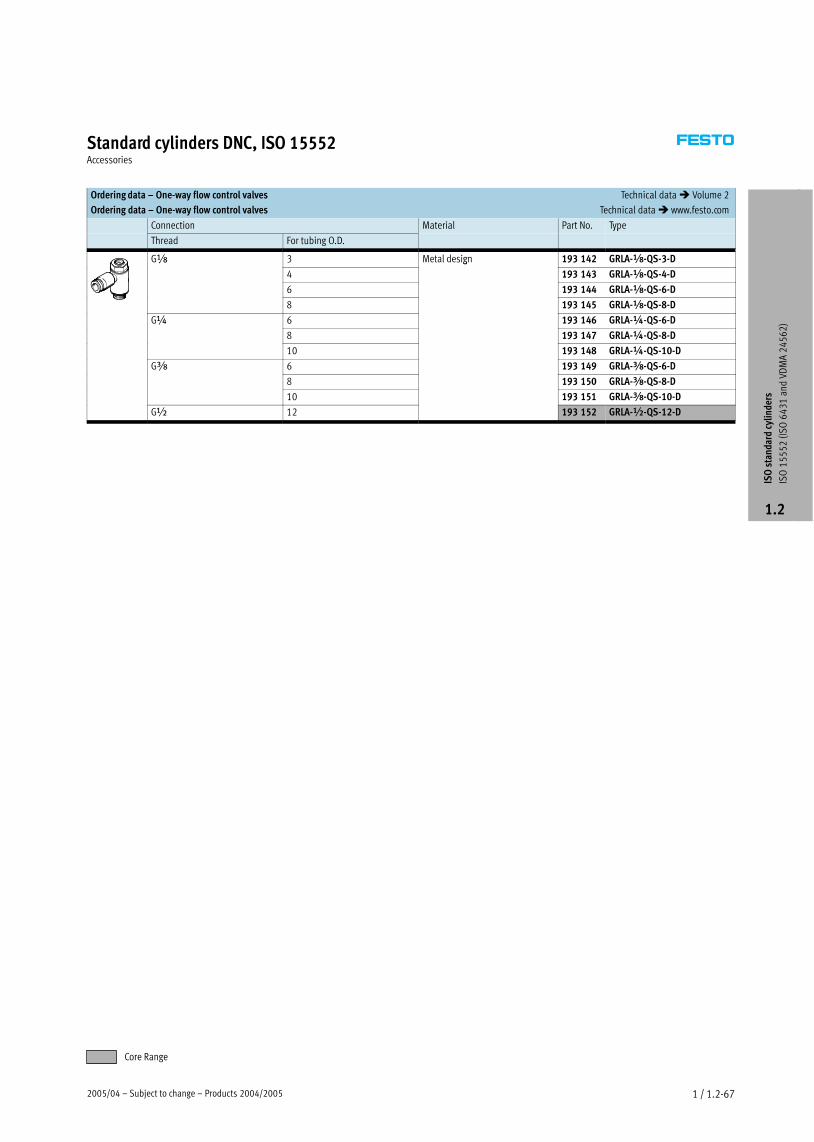
2005/04 – Subject to change – Products 2004/2005 1 / 1.2−67
Standard cylinders DNC, ISO 15552Accessories
Ordering data – One−way flow control valves Technical data � Volume 2
Ordering data – One−way flow control valves Technical data � www.festo.com
Connection Material Part No. Type
Thread For tubing O.D.
yp
Gx 3 Metal design 193 142 GRLA−x−QS−3−Dx
4
g
193 143 GRLA−x−QS−4−D
6 193 144 GRLA−x−QS−6−D
8 193 145 GRLA−x−QS−8−D
G¼ 6 193 146 GRLA−¼−QS−6−D¼
8 193 147 GRLA−¼−QS−8−D
10 193 148 GRLA−¼−QS−10−D
Gy 6 193 149 GRLA−y−QS−6−Dy
8 193 150 GRLA−y−QS−8−D
10 193 151 GRLA−y−QS−10−D
G½ 12 193 152 GRLA−½−QS−12−D
ISO
sta
ndar
d cy
linde
rs
ISO
15
55
2 (I
SO
64
31
and
VD
MA
24
56
2)
1.2
Core Range


