
T OF ENERGYD
EPA
RTMEN
U
E
NIT
ED
STAT S OFA
ER
ICA
M
Office of Energy Efficency and Renewable EnergyU.S. Department of Energy
Steam SystemOpportunity Assessment
for the Pulp and Paper,
Chemical Manufacturing,
and Petroleum RefiningIndustries
Steam SystemOpportunity Assessment
for the Pulp and Paper,
Chemical Manufacturing,
and Petroleum RefiningIndustries
Main ReportMain Report
DownloadCD-ROMZip File
(27.3 MB)

Steam SystemOpportunity Assessment
for the Pulp and Paper,
Chemical Manufacturing,
and Petroleum RefiningIndustries
Steam SystemOpportunity Assessment
for the Pulp and Paper,
Chemical Manufacturing,
and Petroleum RefiningIndustries
Main ReportMain Report

ii Steam System Opportunity Assessment for the Pulp and Paper,
Resource Dynamics Corporation prepared this report for the U.S. Department of Energy’sOffice of Industrial Technologies. Several individuals provided significant assistance in gath-ering, interpreting, and presenting the data for this report. Specific thanks are extended to:
Dr. Anthony L. Wright, Oak Ridge National Laboratory, technical support BestPractices Steam,project manager
Fred Hart, U.S. Department of Energy, Office of Industrial Technologies, BestPractices Steam,program manager
Richard Counts, Oak Ridge National Laboratory, statistical analysis and supportChristopher Russell, Alliance to Save Energy, BestPractices Steam support
Throughout the development of this report, technical review and guidance was provided bythe BestPractices Steam program. Appreciation is extended for the assistance provided by thefollowing committees:
BestPractices Steam Steering CommitteeBestPractices Steam Marketing and Communications SubcommitteeBestPractices Steam Technical SubcommitteeBestPractices Steam Policy and Metrics Subcommittee
Resource Dynamics Corporation would also like to thank the industry experts who providedvaluable data regarding the potential energy savings estimates:
Richard Crain, III, P.E., Parker, Messana, & Associates Management InstituteRobert Dawson, P.E., Dawson Engineering Dr. Herb Eckerlin, North Carolina State UniversityDr. Ahmad Ganji, San Francisco State UniversityRobert Griffin, Enbridge Consumers Gas, Canada Glenn Hahn, Spirax Sarco, Inc.Greg Harrell, P.E., Ph.D., Energy, Environment and Resources Center, University of Tennessee-KnoxvilleDerek Hengeveld, South Dakota State University Kenneth Heselton, KEH Energy EngineeringNevena Iordanova, CEM, Armstrong ServiceDr. Richard Jendrucko, University of Tennessee-KnoxvilleWalter Johnston, P.E.Dr. Beka Kosanovic, University of Massachusetts-AmherstJames Kumana P.E., Kumana and AssociatesAndrew W. Larkin, P.E., CEM, Trigen-Philadelphia Energy CorporationKelly Paffel, P.E., Plant Support and Evaluations, Inc.John Puskar, P.E., CEC ConsultantsCharles G. Turner, Charles G. Turner & Associates Paul Wilson, P.E., Engineered SolutionsDonald Wulfinghoff, P.E. Wulfinghoff Energy Services, Inc.
Resource Dynamics Corporation also acknowledges technical assistance made by the following:
Gary Bases, BRIL Inc.Bruce Gorelick, Enercheck Systems Inc. Mike Sanders, Sunoco Corporation John Todd, Yarway CorporationKevin Hedgers, Energy Saving Audits, Inc.
iiiChemical Manufacturing, and Petroleum Refining Industries
AcknowledgementsAcknowledgements

iv Steam System Opportunity Assessment for the Pulp and Paper,

vChemical Manufacturing, and Petroleum Refining Industries
Table of ContentsTable of Contents
Main Report
Acknowledgements . . . . . . . . . . . . . . . . . . . . . . . . . . . . . . . . . . . . . . .iii
Table of Contents . . . . . . . . . . . . . . . . . . . . . . . . . . . . . . . . . . . . . . . . .v
List of Figures and Tables . . . . . . . . . . . . . . . . . . . . . . . . . . . . . . . . . .vii
Abstract . . . . . . . . . . . . . . . . . . . . . . . . . . . . . . . . . . . . . . . . . . . . . . .xi
1. Executive Summary . . . . . . . . . . . . . . . . . . . . . . . . . . . . . . . . . . . . .1
2. Steam Generation in the Pulp and Paper,Chemical Manufacturing, and Petroleum Refining Industries . . . . . . . . .11
3. Steam Use in the Pulp and Paper,Chemical Manufacturing, and Petroleum Refining Industries . . . . . . . . .23
3.1 Assessing Steam Use in the Pulp and Paper Industry . . . . . . . . . . . . . . . .243.2 Assessing Steam Use in the Chemical Manufacturing Industry . . . . . . . . .373.3 Assessing Steam Use in the Petroleum Refining Industry . . . . . . . . . . . . .52
4. Steam System Performance Improvement Opportunities . . . . . . . . . . . .67
AppendicesThe appendices can be found on a CD-ROM attached to this report or online atwww.oit.gov/bestpractices.
Appendix A: MECS Data for the Pulp and Paper, Chemical Manufacturing, andPetroleum Refining Industries . . . . . . . . . . . . . . . . . . . . . . . . . .Apx-1
Appendix B: Discussion of Assumptions Used in Assessing Energy Data in the Pulp and Paper, Chemical Manufacturing, and Petroleum Refining Industries . . . . . . . . . . . . . . . . . . . . . . . . . . . . . . . .Apx-11
Appendix C: Steam System Performance Improvement Opportunity Descriptions . . .Apx-17Appendix D: Steam System Performance Improvement Opportunity
Questionnaire Description . . . . . . . . . . . . . . . . . . . . . . . . . . .Apx-23Appendix E: Steam System Performance Improvement Opportunity Data Tables . . .Apx-37Appendix F: Analysis of Expert Responses to the Steam System Improvement
Opportunities Questionnaire . . . . . . . . . . . . . . . . . . . . . . . . . .Apx-55Appendix G: Reasons for Implementing Steam System Performance
Improvement Opportunities . . . . . . . . . . . . . . . . . . . . . . . . . . .Apx-63Appendix H: Recommendations for Assessing the Effectiveness of the
BestPractices Steam Program . . . . . . . . . . . . . . . . . . . . . . . . .Apx-67

vi Steam System Opportunity Assessment for the Pulp and Paper,

Section 1—Executive Summary
Figure ES-1. Estimated Steam Energy Use for Major Pulp and Paper Products
Figure ES-2. Estimated Steam Energy Use for 20 Major Chemical Products
Figure ES-3. Estimated Steam Energy Use for Major Petroleum Refining Processes
Figure ES-4. Total Industry Fuel Savings for each Part of the Steam System
Table ES-1. Total Potential Steam System Energy Savings by Industry
Section 2
Table 2-1. Example of Inferring Missing Data in MECS
Table 2-2. Estimated Amount of Fuel Used to Generate Steam by Industry
Table 2-3. Estimated Amount of Steam Generated From Fuel by Industry
Table 2-4. Estimated Amount of Purchased Steam by Industry
Table 2-5. Estimated Total Steam Available to the Target Industry Segments
Table 2-6. Purchased Steam as a Percentage of Total Available Steam by Industry
Table 2-7. Cost of Steam by Industry
Table 2-8. Steam Energy as a Percentage of Total Energy by Industry
Section 3
3.1—Pulp and Paper Industry
Figure 3.1-1. Estimated Steam Energy Use for Major Pulp and Paper Products
Figure 3.1-2. Pulp and Paper Industry Boiler Capacity by Fuel Type
Figure 3.1-3. Pulp and Paper Industry Steam System Capacity by Pressure
Figure 3.1-4. Pulp and Paper Industry Boiler Size Distribution
Table 3.1-1. Energy Use at Integrated Pulp and Paper Mills
Table 3.1-2. Relating Major Pulp and Paper Product to Integrated Plant Type
Table 3.1-3. Pulp and Paper Production Data and Associated Energy Use
Table 3.1-4. Thermal Energy Requirements of Kraft Pulping
Table 3.1-5. Thermal Energy Requirements of Sulfite Pulping
viiChemical Manufacturing, and Petroleum Refining Industries
List of Figures and TablesList of Figures and Tables

Table 3.1-6. Energy Requirements of Selected Mechanical Pulping Processes
Table 3.1-7. Other Pulp and Paper Process Thermal Energy Requirements
Table 3.1-8. Bleaching and Drying Energy Requirements for Mechanical Pulping
Table 3.1-9. Thermal Energy Requirements for Papermaking
Table 3.1-10.Energy Use by Cogeneration Technology
3.2—Chemical Industry
Figure 3.2-1. Estimated Steam Energy Use for 20 Major Chemical Products
Figure 3.2-2. Chemical Industry Boiler Capacity by Boiler Size
Figure 3.2-3. Chemical Industry Boiler Capacity by Fuel Type
Figure 3.2-4. Chemical Industry Steam System Capacity by Pressure
Figure 3.2-5. Cogeneration Fuel Use in the Chemical Industry
Table 3.2-1. Leading Energy-Intensive Chemicals
Table 3.2-2. Energy Use in Ethylene Production
Table 3.2-3. Energy Use in Ammonia Production
Table 3.2-4. Energy Use in Urea Production
Table 3.2-5. Energy Use in Ethylbenzene/Styrene Production
Table 3.2-6. Energy Use in Polystyrene Production
Table 3.2-7. Energy Use in Chlorine/Sodium Hydroxide Production
Table 3.2-8. Energy Use in Ethylene Dichloride/PVC Production
Table 3.2-9. Energy Use in Phenol/Acetone Production
Table 3.2-10.Energy Use in Benzene, Toluene, and Xylene Production
Table 3.2-11.Energy Use in Caprolactum Production
Table 3.2-12.Energy Use in Sodium Carbonate Production
Table 3.2-13.Energy Use in Polybutadiene Rubber Production
Table 3.2-14.Energy use in Styrene Butadiene Rubber Production
Table 3.2-15.Energy Use in Butyl Rubber Production
Table 3.2-16.Energy Use in Cyclohexane Production
3.3—Petroleum Industry
Figure 3.3-1. Estimated Steam Energy Use for Major Petroleum Refining Processes
Figure 3.3-2. Basic Process Flow of a Petroleum Refinery
Figure 3.3-3. Boiler Capacity in the Petroleum Industry by Boiler Size
viii Steam System Opportunity Assessment for the Pulp and Paper,

Figure 3.3-4. Petroleum Industry Boiler Capacity by Fuel Type
Figure 3.3-5. Petroleum Industry Steam System Capacity by Pressure
Table 3.3-1. Energy Requirements of Common Refinery Processes
Table 3.3-2. Estimated Steam Generation Capacity by Cogeneration in the Petroleum Industry (MMBtu/hr)
Section 4
Figure 4-1. Total Industry Fuel Savings for Each Part of the Steam System
Figure 4-2. The Majority of General Opportunity Fuel Savings Were Greater Than 1 Percent
Figure 4-3. Facilities Where General Opportunities are Feasible Ranged from 3 to 29 Percent.
Figure 4-4. Simple Paybacks for Steam System Improvements Were Reported to be Typically Less Than 2 Years
Figure 4-5. Total Fuel Savings for General Steam Improvement is About 4 Percent.
Figure 4-6. Typical Industry Fuel Savings for Each Major Area of the Steam System
Figure 4-7. Total Industry Fuel Savings for Each Part of the Steam System
Table 4-1. Total Potential Steam System Energy Savings by Industry
Table 4-2. General Opportunity Fuel Savings
Table 4-3. Percentage of Facilities Where the General Opportunities are Feasible
Table 4-4. Payback Period by Opportunity
Table 4-5. Industry Fuel Savings by General Opportunity
Table 4-6. Results for the End-Use Opportunities
Table 4-7. Data for Improving Water Treatment Practices
Table 4-8. Data for Improving Steam Trap Management
Table 4-9. Data for Improving Steam System Insulation
Table 4-10. Data for Improving Plant-Wide Testing and Maintenance
Table 4-11. Typical Fuel Savings for Each Major Area of the Steam System
Table 4-12. Total Industry Fuel Savings for Each Part of the Steam System
Table 4-13. Total Percentage Fuel Savings by Industry
Table 4-14. Total Potential Steam System Energy Savings by Industry
List of Figures and Tables
ixChemical Manufacturing, and Petroleum Refining Industries

x Steam System Opportunity Assessment for the Pulp and Paper,

This report assesses steam generation and use in the pulp and paper, chemicalmanufacturing, and the petroleum refining industries. The amount of fuel used togenerate steam is determined using a U.S. Department of Energy report, titledManufacturing Consumption of Energy 1994, which is based on data collected fromthe Manufacturing Energy Consumption Survey 1994 (MECS). The amount of steamthat is used by the three target industries is estimated by evaluating the moststeam intensive products and processes, determining the amount of steam requiredper pound of output, and combining production data for these products andprocesses to determine overall industry steam use.
Estimates of the amounts of fuel used to generate steam in target industries were:
• Pulp and paper: 2,221 trillion Btu• Chemical manufacturing: 1,540 trillion Btu• Petroleum refining: 1,675 trillion Btu.
This report also estimated the energy savings potential available from implement-ing steam system performance and efficiency improvements. Using expert elicita-tion, the savings available from 30 steam system improvements were estimated toexceed 12 percent for each of the three industries. Significant opportunities wereavailable in all parts of the system.
xiChemical Manufacturing, and Petroleum Refining Industries
AbstractAbstract

xii Steam System Opportunity Assessment for the Pulp and Paper,

Executive SummaryFigures and Tables referenced in this section begin on page 7 in the order they are men-tioned in the text.
ES.1 Introduction
The U.S. Department of Energy (DOE) Office of Industrial Technologies (OIT)BestPractices efforts aim to assist U.S. industry in adopting near-term, energy-effi-cient technologies and practices through voluntary technical-assistance programson improved system efficiency. There are nine industry groups—designatedIndustries of the Future (IOFs)—that are the focus of the OIT efforts. These IOFsinclude Agriculture, Aluminum, Chemicals, Forest Products, Glass, Metal Casting,Mining, Petroleum, and Steel. BestPractices efforts cover motor-driven systems, suchas pumps and fans, compressed air, steam, and process heating systems.
The overall goal of the BestPractices Steam effort is to assist steam users in adopt-ing a systems approach to designing, installing, and operating boilers, distributionsystems, and steam applications. In June 2000, Resource Dynamics Corporation(RDC), under contract with the Oak Ridge National Laboratory (ORNL) with fund-ing from DOE-OIT, initiated an Industrial Steam System Opportunity Assessment.The purposes of the Steam System Opportunity Assessment effort are:
• To develop baseline data on steam generation and use by the pulp andpaper, petroleum refining, and chemical manufacturing industries
• To develop baseline data on potential opportunities available for improvingthe energy efficiency of industrial steam systems for these three industries.
This Opportunity Assessment focused on the pulp and paper, chemical, and petro-leum refining industries because these three industries are the major IOF steamenergy users. The primary audience for the results from this assessment includessteam system end users (CEOs/CFOs, energy managers, plant managers, and oper-ators); steam system equipment and service suppliers; and DOE program manage-ment.
The data generated from this Opportunity Assessment can be used to illustrate themagnitudes of steam system improvement opportunities available for the three tar-geted industries. The steam system improvement opportunity data from this assess-ment should also be relevant to other industries that utilize steam. This ExecutiveSummary presents and discusses the major results from this study.
ES.2 Steam Generation in the Pulp and Paper, ChemicalManufacturing, and Petroleum Refining Industries
Steam energy accounts for a significant amount of the total industrial process ener-gy use particularly among the IOFs. Because IOFs represent both an important
1Chemical Manufacturing, and Petroleum Refining Industries
Section 1—Executive SummarySection 1—Executive Summary

national interest and a large portion of the nation’s overall energy use, it is impor-tant not only to understand how these industries use energy, but especially howthey generate and use steam. Section 2 of the report assesses steam generation—specifically the amount of fuel used to generate steam and the amount of steamthat is generated—by three important IOF industries—pulp and paper, chemicalmanufacturing, and petroleum refining. Combining data from the ManufacturingEnergy Consumption Survey 1994 (MECS), with energy use estimates for key processesand products, Section 2 provides a top-down analysis of the steam generation inthe three target industries.
Key ResultsAccording to MECS data, the amounts of fuel used to generate steam in the targetindustries were:
• Pulp and paper manufacturing: 2,221 trillion British thermal units (Btu)• Chemical manufacturing: 1,540 trillion Btu• Petroleum refining: 1,675 trillion Btu.
Section 2 also estimates the amount of steam generated by this fuel, the amount ofsteam purchased, and the total amount of steam available to these industries. Theamount of steam as a percentage of total energy used by each industry was alsodetermined:
• Pulp and paper manufacturing: 84 percent• Chemical manufacturing: 47 percent• Petroleum refining: 51 percent.
ES.3 Steam Use in the Pulp and Paper Industry
Manufacturing plants in the pulp and paper industry vary by size, level of integra-tion, process technology, wood type, and final product type. The energy used byfully integrated plants can be combined with total industry production to estimatethe total thermal energy used by the pulp and paper industry. This methodassumes that a fully integrated pulp and paper plant uses the same amount ofenergy to produce a ton of product that an equivalent supply chain of plants thatare not integrated would use. Ideally, the energy data reported in the MECS is con-sistent with the results of this bottom up view of the process energy use.
Key ResultsA bottom-up steam energy useevaluation of the pulp andpaper industry for 14 majorproducts indicates that the ther-mal energy requirements rangebetween 1,212 and 2,735 trillionBtu. The average pulp andpaper total steam energy use,based on this data, is 1,947 tril-lion Btu. Because this is an end-use estimate, determining thecorresponding amount of fuel
use requires assuming a conversion efficiency, which accounts for losses in generat-ing and distributing the steam to the end use. Assuming 75 percent of the fuel
2 Steam System Opportunity Assessment for the Pulp and Paper,
The amount of steam energy required to produce
14 key pulp and paper products ranges between
4 and 483 trillion Btu.
TAPP
I Jou
rnal
/NRE
L/PI
X 03
221

energy is converted to steam and delivered to the end use, the fuel use data is 2,596trillion Btu. According to MECS, the fuel used to generate steam in the pulp andpaper industry was 2,221 trillion Btu, which is about 14 percent less than the 2,596trillion Btu value. Although there are many assumptions built into this model, therelative agreement between these data indicates that these assumptions are reason-able.
The estimated steam energy requirements for these 14 major pulp and paper prod-ucts are presented in Figure ES-1. The product steam energy use requirements var-ied between 4 and 483 trillion Btu.
The sources of the steam in pulp and paper manufacturing include recovery boilers(at chemical pulping facilities), power boilers, and waste heat recovery boilers.There is approximately 370,000 million Btu per hour (MMBtu/hr) of boiler capacityin the pulp and paper industry. Approximately half of this boiler capacity is firedby waste fuels. Most of the boiler capacity for pulp and paper plants is in the pres-sure range of 300 to 1,000 pounds per square inch (psig). Boilers larger than 250MMBtu/hr account for over half of the boiler capacity in this industry.
ES.4 Steam Use in the Chemical Manufacturing Industry
The chemical manufacturing industry uses a significant amount of energy to man-ufacture chemical products for consumer and industrial markets. However, theprocesses used by chemical manufacturers to produce these products are typicallyconsidered competitive information, making it difficult to assess energy use in thisindustry from a process perspective. Consequently, a different approach to assess-ing chemical industry steam generation and use is required. Because a relativelysmall number of chemical products account for most of the industry’s energy use,evaluating the processes used to manufacture these high energy-use chemical prod-ucts can provide a reasonably accurate assessment of how energy, specificallysteam energy, is used.
Key ResultsThe chemical industry produces over 70,000 products. In 1994, the chemical indus-try used about 3,273 trillion Btu of energy, of which steam energy accounts forroughly 1,540 trillion Btu (see Section 2). Within the chemical industry (SIC 28),there are nine 4-digit SIC segments that account for 1,210 trillion Btu of fuel usedto generate steam, which is approximately 79 percent of the industry total. Withinthese nine SIC segments, there are 20 chemical products whose process steam ener-gy requirements account for 832 trillion Btu of steam.
The estimated steam energy requirements for these 20 major chemicals are shownin Figure ES-2. The steam energy requirements for these 20 products varied between0.3 and 343 trillion Btu.
Using a 75 percent conversion efficiency, which accounts for losses in convertingfuel to thermal energy, generating steam, and delivering it to the end uses, the 832 trillion Btu of steam energy translates to 1,109 trillion Btu of fuel energy.Consequently, evaluation of the process energy requirements of these 20 chemicalproducts accounts for 90 percent of the steam use within the nine selected SICs and71 percent of the total industry steam use.
The sources of steam in the chemical manufacturing industry include boilers andprocess heat recovery heat exchangers. The estimated boiler capacity in the chemi-
Section 1—Executive Summary
3Chemical Manufacturing, and Petroleum Refining Industries

cal manufacturing industry isabout 500,000 MMBtu/hr. Overhalf of this capacity, about 280MMBtu/hr, is accounted for byboilers above 100 MMBtu/hr.However, small boilers between10 and 50 MMBtu/hr accountfor about 120,000 MMBtu/hr ofindustry capacity, illustratingthe wide distribution of boilersize across the industry. Naturalgas is the dominant fuel type,accounting for about 205,000MMBtu/hr of industry boilercapacity. About 60 percent of
the boiler capacity lies in the pressure range between 300 and 1,000 psig.
ES.5 Steam Use in the Petroleum Refining Industry
The petroleum refining industry uses energy to convert crude oil into many differ-ent products, some of which are used directly by consumers, while others are feed-stocks for other industries. Production data for these petroleum refining processescan be combined with process energy data to estimate overall industry energy use.Additionally, the component energy types, including direct-fired, electric, andsteam, can be disaggregated from the energy data for each refining process. Thisallocation allows the total steam use within the industry to be estimated. Thissteam use estimate can then be compared to the amount of fuel used to generatesteam as indicated by MECS.
Section 3.3 describes energy data for steam use by key end use processes. Section3.3 also describes how steam is used by the major refining processes and discussessources of steam generation.
Key ResultsThere are 11 major refining processes that represent the principal end uses ofsteam in the petroleum refining industry. The estimated steam energy require-ments for major petroleum refining processes are presented in Figure ES-3. Processsteam energy-use requirements vary between 0.5 and 246.1 trillion Btu. Note thatvisbreaking and coking operations are net steam producers.
The sum of the energy use for these 11 processes is 900 trillion Btu. If a steam sys-tem efficiency of 75 percent is assumed, the total fuel used to generate steam basedon the process data becomes 1,200 (= 900/0.75) trillion Btu. Section 2 of this reportestimates that the petroleum refining industry used 1,675 trillion Btu for steamgeneration. These two estimates of fuel used to generate steam in the petroleumrefining industry compare favorably.
The major sources of steam generation in the petroleum refining industry are boilersand heat recovery steam generators. The estimated boiler capacity in the refiningindustry is about 210,000 MMBtu/hr. Boilers that generate more than 250 MMBtu/hraccount for about 100,000 MMBtu/hr, or roughly 48 percent of the industry’s total
4 Steam System Opportunity Assessment for the Pulp and Paper,
Within the chemical industry, 20 major chemical
products account for 832 trillion Btu of steam.

boiler capacity. Most of the boiler capacity in the petroleum refining industry isfired by byproduct fuels such as refinery gas and coke. In terms of steam systempressure, about 60 percent of the total industry boiler capacity is at 300 psig or less.Most of the remaining boiler capacity is between 300 and 1,000 psig.
ES.6 Steam System Performance Improvement Opportunities
Section 4 of the report estimates the potential savings available from implementingsteam system improvements in the pulp and paper, chemical manufacturing, andpetroleum refining industries. To develop these savings estimates, 30 performanceimprovement opportunities were identified that cover the most significant ways toimprove steam system performance and efficiency in these target industries.
To assess the energy savings available from implementing steam system improve-ments, it was determined that eliciting expert opinion would be the most effectiveapproach. Expert judgment was elicited by sending questionnaires to qualifiedexperts. The major types of data requested were:
• Fuel savings• Percentage of facility for which each opportunity is feasible• Payback period• Reasons for implementing the improvement.
Section 4 of the report presents data gathered from this approach.
Key ResultsThe results of this effort indicate that fuel savings from individual steam systemimprovements range from 0.6 percent to 5.2 percent. The payback periods for thesesteam system improvements range from 2 to 34 months; the majority are less than24 months. The percentages of facilities for which these improvements are feasiblerange from 3.4 to 29.4 percent.
Overall industry fuel savings, which are the combination of estimates for fuel sav-ings and the percentage of facilities for which an opportunity is feasible for each ofthe 30 opportunities, range from 0.02 percent to 3.0 percent. The data showingoverall fuel savings for themajor areas of a steam systemare shown in Figure ES-4.
When combined, the totalpotential fuel savings from thesesteam system improvementopportunities totaled over 12percent for each industry. TableES-1 indicates that the total esti-mated energy savings potentialfor these 30 steam systemimprovement opportunities is674 trillion Btu.
Section 1—Executive Summary
5Chemical Manufacturing, and Petroleum Refining Industries
The major sources of steam generation in the petroleum refining industry are boilers and heat recovery steam generators.
NREL
/PIX
050
49

This data illustrates several key results.
• Individual fuel saving opportunities can be significant, especially becausefacilities can often implement several steam system improvements.
• Because most payback periods are less than 2 years, these improvements aregenerally worth considering.
• Total potential energy savings associated with steam improvements is signifi-cant, amounting to over 12 percent for each target industry.
ES.7 Summary of Information Included in the Appendices
The appendices for the report contain:
• Supporting information for the analyses• Suggestions and recommendations for assessing the effectiveness of the U.S.
Department of Energy BestPractices Steam Program.
6 Steam System Opportunity Assessment for the Pulp and Paper,

Section 1—Executive Summary
7Chemical Manufacturing, and Petroleum Refining Industries
Figure ES-1. Estimated Steam Energy Use for Major Pulp and Paper Products
Recycled Paperboard
Semichemical Paperboard
Solid Bleached Paperboard
Unbleached Kraft Paperboard
Bleached, Speciality Packaging
Unbleached Kraft
Tissue
Thin Papers
Cotton Fiber
Bleached Bristols
Uncoated Free Sheets
Coated Paper
Groundwood Printing & Converting
Newsprint
0 100 200 300
Trillion Btu
400 500
Figure ES-2. Estimated Steam Energy Use for 20 Major Chemical Products
Cyclohexane
Butyl Rubber
Styrene Butadiene Rubber
Polybutadiene Rubber
Urea
Sodium Carbonate
Caprolactum
Benzene, Toluene, and Xylene
Phenol/Acetone
Ethylene Dichloride/Polyvinyl Chloride
Chlorine/Sodium Hydroxide
Polystyrene
Ethylbenzene/Styrene
Ammonia
Ethylene
0 100 200 300
Trillion Btu
400

8 Steam System Opportunity Assessment for the Pulp and Paper,
Figure ES-3. Estimated Steam Energy Use for Major Petroleum Refining Processes
Isopentane/Isohexane
Isobutane
Alkylation
Catalytic Reforming
Catlaytic Hydrotreating
Catalytic Hydrocracking
Fluid Catalytic Cracking
Coking Operations
Visbreaking
Vacuum Distillation
Atmospheric Distillation
-100 0 100 200 300
Trillion Btu
Table ES-1. Total Potential Steam System Energy Savings by Industry
Industry Fuel Fuel Used to Generate Savings PotentialIndustry Savings (%) Steam (Trillion Btu) (Trillion Btu)
Pulp and Paper 12.5 2,221 278
Chemical Manufacturing 12.4 1,540 191
Petroleum Refining 12.2 1,675 205
Total 674
Figure ES-4. Total Industry Fuel Savings for Each Part of the Steam System
Special Opportunities—Plant-Wide Testing/Maintenance
Special Opportunities—Insulation
Special Opportunities—Steam Trap Management
Special Opportunities—Water Treatment
Combined Heat and Power
Recovery
End Use—Petroleum Refining
End Use—Chemical Manufacturing
End Use—Pulp and Paper
Distribution
Generation
0 0.50 1.00 1.50
Industry Fuel Savings (%)
Note that the Recovery, all the End-Use Opportunities, the Distribution, and the Generation categories include multiple opportunities.
2.00 2.50 3.00

9Chemical Manufacturing, and Petroleum Refining Industries

10 Steam System Opportunity Assessment for the Pulp and Paper,

Steam Generation in the Pulp and Paper, Chemical Manufacturing,and Petroleum Refining IndustriesFigures and Tables referenced in thissection begin on page 16 in the ordermentioned in the text.
Introduction Steam energy accounts for a signif-icant amount of the total industri-al process energy use particularlyamong the Industries of the Future(IOFs)1. Because IOFs representboth an important national inter-est and a large portion of thenation’s overall energy use, it isimportant to not only understandhow these industries use energy,but especially how they generate and use steam. This section assesses steam gener-ation—specifically the amount of fuel used to generate steam and the amount ofsteam that is generated—by three important IOF industries—pulp and paper,chemical manufacturing, and petroleum refining. Combining data from theManufacturing Energy Consumption Survey 1994 (MECS) with energy use estimates forkey processes and products, this section provides a top-down analysis of the steamgeneration in the three target industries.
Key ResultsAccording to MECS data, the amounts of fuel used to generate steam in the targetindustries were:
• Pulp and paper: 2,221 trillion Btu• Chemical manufacturing: 1,540 trillion Btu• Petroleum refining: 1,675 trillion Btu.
This section also estimates the amount of steam generated by this fuel, the amountof steam purchased, and the total amount of steam available to these industries.The amount of steam as a percentage of total energy used by each industry wasalso determined:
• Pulp and paper: 84 percent• Chemical manufacturing: 47 percent• Petroleum refining: 51 percent.
11Chemical Manufacturing, and Petroleum Refining Industries
Section 2Section 2
The pulp and paper industry is among the three most steam-intensiveIndustries of the Future.Steam accounts for 84 percent of total energy use in the industry.
1 Industries of the Future (IOF) include: Agriculture, Aluminum, Chemicals, ForestProducts, Glass, Metal Casting, Mining, Petroleum Refining, and Steel.
TAPP
I Jou
rnal
/NRE
L/PI
X 03
228

Evaluating MECS DataMECS provides the most comprehensive data for fuel use in the target industries.MECS provides fuel use data at the 4-digit SIC level, reporting energy data bymany different criteria in 44 different tables. The basis for determining energy usein the target industries is in the MECS table titled “Total Inputs of Energy for Heat,Power, and Electricity Generation by Fuel Type, Industry Group, Selected Industriesand End Use.” This table contains two parts: Part 1 reports data by the physicalunits of each fuel type, such as kWh, barrels of oil, and cubic feet of gas; Part 2reports the data for all fuel types in trillion Btu. Because several different fuel typesmust be compared, Part 2 provides the more reasonable basis for this assessment.
However, many of the data are missing because of several possible reasons, includ-ing:
• Nondisclosure of competitive information (indicated by W)• Insufficient statistical confidence (indicated by Q)• Inadequate data (indicated by *).
In many instances, missing, omitted data can be inferred from other data. Forexample, total fuel use by fuel type or end use can provide one way of estimatingfuel use where such data is omitted. Table 2-1 shows an example of how the miss-ing data were inferred. The results of inferring this data for all target SICs arefound in Appendix A, titled MECS Data for the Pulp and Paper, ChemicalManufacturing, and Petroleum Refining Industries.
Determining the Fuel Used to Generate Steam with MECS DataAfter the missing data is inferred, the fuel that is used to generate steam must beassessed. Fuel use is reported in “Indirect Uses—Boiler Fuel”, in “End use not report-ed” (EUNR), and in “Conventional electricity generation.” EUNR data does notinclude fuel use listed either in the Direct or Indirect End Uses. Additionally, theEUNR data primarily consists of “Other” fuels. MECS uses the “Other” fuel columnto account for energy that is not included in the major energy sources. Examples of“Other” fuels include coke, refinery gas, wood chips, and other solid waste fuels.
For the pulp and paper industry, EUNR data is allocated entirely to boiler fuels.This assumption is based on the steam-intensive nature of the processes in thisindustry. In the pulp and paper industry, the use of furnaces, kilns, and otherdirect fired equipment is relatively small with respect to the generation of steam.Additionally, although gasification technologies are available, they are not widelyused, leaving boilers the dominant fuel-to-energy conversion source for waste fuels.Consequently, in the pulp and paper industry, there is relatively high confidence inassuming that waste fuel use is entirely for steam generation.
In the chemical industry segments, there are many more products and productionprocesses. Many of these processes are steam-intensive and a large portion of thewaste fuel-to-energy conversion process is performed in boilers (again, gasificationis not considered a significant conversion technology). However, there are alsodirect-fired applications that influence the allocation of MECS fuel use data. Forexample, ethylene and propylene production require large quantities of fuel to firepyrolysis furnaces. Because a significant portion of the fuel used in pyrolysis fur-naces is byproduct fuel, this fuel use is listed as “Other” and is found in the EUNRclassification2.
12 Steam System Opportunity Assessment for the Pulp and Paper,
2 Gas Research Institute, 1992 Industrial Process Heat Energy Analysis, September 1996.

Similarly, in the petroleum industry, there are several processes that use waste fuelsboth to generate steam and to provide direct heating for other processes. To deter-mine the appropriate allocation of “Other” fuel to steam generation, petroleumrefining processes that use byproduct fuels must be assessed. Significant sources of“Other” energy in the petroleum refining processes include still gas and liquefiedpetroleum gas (LPG) byproducts from refining processes. Significant amounts ofthese gases are used in direct-fired applications, such as visbreaking heaters andother reaction vessels. For example, in 1992, 894 trillion Btu of byproduct fuel wereused in direct-fired applications in the petroleum industry3. To infer the amount ofdirect-fired fuel use in 1994, the value of shipments for the petroleum refiningindustry during 1992 and 1994 level were compared. Assuming no significant dif-ference in process technologies between the 2 years, this correction is simply theratio of the values of shipments for 1994 and 1992 multiplied by the amount ofdirect-fired fuel use in 1992. As further information is gathered regarding theprocesses in the petroleum industry, this estimate may be adjusted.
Another component of fuel that is included in the industry total for generatingsteam is conventional electricity generation. A key assumption in allocating thisfuel use to steam is that all on-site electric generation is assumed to be an electrictopping-cycle cogeneration application that generates steam from the waste heat.An important factor in this assumption is that the thermal requirements for thetarget industries make on-site electricity generation equipment, such as enginesand turbines, highly feasible for waste heat recovery. Because the fuel is burned togenerate both electricity and steam, the conversion factors from fuel to steam willbe smaller than those applied to boilers. In this study, the amount of energy avail-able for steam generation is set at 65 percent of the fuel used to generate electricity.This assumes the efficiency of the engine or turbine is 35 percent, leaving theremaining energy available for heat recovery.
Table 2-2 provides the estimated amount of energy used to generate steam by industry.
Fuel to Steam ConversionTo convert the fuel energy data into steam usage, an assessment of the conversionequipment and efficiencies is required. Boiler efficiency can be estimated but theaccuracy of this estimate depends on many factors, including operating practices,boiler age, control system sophistication, and maintenance practices. Table 2-3 pro-vides the estimated amount of steam generated from the fuel use data provided inTable 2-2.
Table 2-3 uses several important assumptions, including:
• Boiler efficiency was calculated for each SIC group by allocating average boil-er efficiencies for each fuel type to the amount of fuel used by each industry.For example, the efficiency of a boiler fired with spent liquor is 65 percent; theefficiency of a boiler fired with coal is 81 percent4. These boiler efficiencies aredesign values and do not reflect the effects of poor operating and mainte-nance practices.
Section 2
13Chemical Manufacturing, and Petroleum Refining Industries
3 Ibid.4 Giraldo, Luis and Hyman, Barry, Energy End-Use Models for Pulp, Paper, and Paperboard
Mills, Department of Mechanical Engineering, University of Washington, 1995.

• In cogeneration applications, an estimated 52 percent of the fuel burned inthe engine is recovered as steam. This estimate assumes the engine efficiencyis 35 percent, leaving 65 percent of the fuel energy available as waste heat.Consequently, the fuel data from the “Conventional Electricity Generation”column in Table 2-2 of this report reflects the 65 percent of the fuel fromMECS . The steam data in Table 2-3 reflects a heat recovery efficiency of 80percent.
• Converting fuel use into a steam equivalent requires assuming a representa-tive energy content of steam. Selecting an average steam pressure of 300 psigand a feedwater temperature of 80°F results in an energy content of 1,150Btu/lb.
Purchased SteamAnother source of steam for many plants is through purchases from utility or non-utility suppliers. Utility suppliers are typically electric power producers that havecogeneration equipment and export steam to nearby industrial customers. Non-utility suppliers are typically industrial facilities that cogenerate a sufficient quan-tity of steam to meet their internal requirements and to export to nearby plants.Much of the market for purchased steam is attributable to the Public UtilityRegulatory Policies Act (PURPA), which Congress enacted in 1977 to reduce manyof the barriers to industrial cogeneration of electricity and steam. A major intent ofPURPA was to expand cogeneration in an effort to improve overall industrial ener-gy efficiency and to reduce reliance on energy imports. A result of PURPA wasincreased investment in cogeneration capacity that continued into the late 1980s.
Many cogenerating facilities sell steam to nearby industrial customers. Theamount of steam purchased by the target industries in 1994 is shown in Table 2-4.The data are provided in terms of energy (trillion Btu) and mass (millions ofpounds), and the conversion assumes steam contains 1,150 Btu/lb. In some indus-tries, specifically Alkalies and Chlorine (SIC 2812), Inorganic Pigments (SIC 2819),and Synthetic Rubber (SIC 2822), the amount of purchased steam compared to thetotal amount of steam is relatively high.
Total Steam Available to the Target IndustriesThe total amount of steam available to industry is the sum of the steam generatedon site and the steam purchased from suppliers. Table 2-5 provides the totalamount of steam energy available to the target industry processes. The on-site gen-erated steam data for Table 2-5 takes the steam data from Table 2-3 and performsthe conversion to trillion Btu using a steam energy value of 1,150 Btu/lb.
Table 2-6 shows the percentages of purchased steam with respect to the total avail-able steam.
Cost of SteamTable 2-7 estimates the costs of steam generation in these industries. In this table,steam is valued at $6.00 per 1,000 lbs. However, steam costs can vary widely,depending on factors such as fuel type, fuel purchase contracts, and labor andmaintenance costs. Additionally, labor and maintenance costs vary according tosystem size, complexity, and operating characteristics. If waste fuels account formost of the steam production, then cost of steam may be below $2.00 per 1,000 lbs.
14 Steam System Opportunity Assessment for the Pulp and Paper,

Conversely, if natural gas is purchased on the spot market, with prices as high as$10.50 per MMBtu5, then steam costs can reach $17.25 per 1,000 lbs (assuming1,150 Btu/lb steam and 70 percent boiler efficiency).
Steam Use as a Percentage of Overall Energy UseTable 2-8 shows how much of an industry’s total energy use is accounted for bysteam. In the pulp and paper industry, steam is by far the dominant form of ener-gy use, representing between 84 and 92 percent of the total energy used. Thesteam-intensive nature of these industries reflects the large process heating require-ment and the availability of waste-fuel energy that is typically used to generatesteam.
The chemical manufacturing industry shows a greater variance in steam usebecause of its wide range of manufacturing processes. However, in general, thechemical industry is steam intensive, using about 47 percent of its total energy inthe form of steam. The chemical industry segments have steam use characteristicsthat range from 30 to 70 percent of their respective total energy use. The petroleumrefining industry uses about 51 percent of its energy in the form of steam.
Section 2
15Chemical Manufacturing, and Petroleum Refining Industries
5 Henry Hub market price, Energy Information Administration, Oil and Gas Office,February 26, 2001.

16 Steam System Opportunity Assessment for the Pulp and Paper,
Table 2-1. Example of Inferring Missing Data in MECS
Paper Mills (SIC 2621)
Total Inputs
Indirect Uses—Boiler Fuel
Total Process (Direct Uses)
Process Heating
Process Cooling and Refrigeration
Machine Drive
Electro-Chemical
Other
Total Non-Process (Direct Uses)
Facility HVAC
Facility Lighting
Facility Support
On-Site Transportation
Conventional Electricity Generation
Other Non-Process Use
End Use Not Reported
Total
1,292
-
-
-
-
-
-
-
-
-
-
-
-
-
-
614
NetElectricity
117
1
106
1
1
102
*
2
8
4
3
1
*
-
*
2
ResidualFuel Oil
94
76
17
17
0
1
-
0
w
w
0
w
0
w
w
w
DistillateFuel Oil
4
2
1
1
0
*
-
*
1
0
0
0
1
0
0
0
NaturalGas
271
195
48
44
*
w
-
w
26
3
0
0
0
23
0
2
LPG
2
w
1
1
0
0
0
0
1
0
0
0
1
0
0
0
Coal
195
w
w
w
0
w
-
0
w
w
-
0
-
w
0
0
Other
609
-
-
-
-
-
-
-
-
-
-
-
-
-
-
609
Original Results Data Inputs
Total Inputs for Heat, Power, and Electricity Generation by Fuel Type, Industry Group, Selected Industries and EndUse, 1994: Part 2.
indicates inferred data
Paper Mills (2621)
Total Inputs
Indirect Uses—Boiler Fuel
Total Process (Direct Uses)
Process Heating
Process Cooling and Refrigeration
Machine Drive
Electro-Chemical
Other
Total Non-Process (Direct Uses)
Facility HVAC
Facility Lighting
Facility Support
On-Site Transportation
Conventional Electricity Generation
Other Non-Process Use
End Use Not Reported
Total
1,292
-
-
-
-
-
-
-
-
-
-
-
-
-
-
613
NetElectricity
117
1
106
1
1
102
0
2
8
4
3
1
0
0
0
2
ResidualFuel Oil
94
76
17
17
0
1
0
0
0
0
0
0
0
0
0
0
DistillateFuel Oil
4
2
1
1
0
0
0
0
1
0
0
0
1
0
0
0
NaturalGas
271
195
48
44
0
0
0
0
26
3
0
0
0
23
0
2
LPG
2
0
1
1
0
0
0
0
1
0
0
0
1
0
0
0
Coal
195
185
5
0
0
0
0
0
5
0
0
0
0
0
0
0
Other
609
0
0
0
0
0
0
0
0
0
0
0
0
0
0
609
Results of Inferring Data
- indicates no data entered
* indicates a value less than 0.5
w indicates data withheld to avoid disclosing establishment

Section 2
17Chemical Manufacturing, and Petroleum Refining Industries
Table 2-2. Estimated Amount of Fuel Used to Generate Steam by Industry
Pulp and Paper
Pulp Mills
Paper Mills
Paperboard Mills
Other Pulp and Paper Segments
Chemicals
Alkalies and Chlorine
Inorganic Pigments
Inorganic Chemicals
Plastics and Resins
Synthetic Rubber
Organic Fibers, Noncellulosic
Cyclic Crudes and Intermediates
Organic Chemicals
Nitrogenous Fertilizers
Other Chemical Segments
Petroleum
Petroleum Refining
Other Petroleum Refining Segments
SIC
26
2611
2621
2631
28
2812
2816
2819
2821
2822
2824
2865
2869
2873
29
2911
Total
2,221
231
1,085
827
78
1,540
81
20
126
187
32
80
111
488
86
330
1,675
1,655
20
Indirect UsesBoiler Fuel
849
40
459
288
62
1,229
51
10
101
137
23
72
81
389
72
293
304
295
9
End UseNot Reported
1,351
191
611
533
16
184
30
10
23
50
9
8
27
11
13
3
1,323
1,313
11
ConventionalElectricity Generation
20
0
15
6
0
127
0
0
1
0
0
0
3
88
1
34
47
47
0
Units are Trillion Btu
Table 2-3. Estimated Amount of Steam Generated from Fuel by Industry
Industry Description
Pulp and Paper
Pulp Mills
Paper Mills
Paperboard Mills
Other Pulp and Paper Segments
Chemicals
Alkalies and Chlorine
Inorganic Pigments
Inorganic Chemicals
Plastics and Resins
Synthetic Rubber
Organic Fibers, Noncellulosic
Cyclic Crudes and Intermediates
Organic Chemicals
Nitrogenous Fertilizers
Other Chemical Segments
Petroleum
Petroleum Refining
Other Petroleum Refining Segments
SIC
26
2611
2621
2631
28
2812
2816
2819
2821
2822
2824
2865
2869
2873
29
2911
Total
1,382,103
136,509
660,774
509,520
75,301
1,055,577
54,629
13,808
86,851
126,311
21,880
56,157
76,000
326,191
60,988
232,762
1,140,811
1,127,262
13,549
Indirect UsesBoiler Fuel
527,857
23,617
278,992
177,308
47,939
841,277
34,396
6,870
69,892
92,505
15,726
50,450
55,643
257,687
50,895
207,213
207,052
200,857
6,196
End UseNot Reported
840,094
112,891
371,382
328,143
27,678
125,952
20,233
6,938
16,054
33,761
6,154
5,707
18,548
7,287
9,189
2,081
901,063
893,709
7,353
ConventionalElectricity Generation
14,153
0
10,400
4,070
0
88,348
0
0
904
45
0
0
1,809
61,217
904
23,468
32,696
32,696
0
Units are Million Lbs. of SteamNote: Row and column totals are subject to rounding errors.

18 Steam System Opportunity Assessment for the Pulp and Paper,
Table 2-4. Estimated Amount of Purchased Steam by Industry
Industry Segment
Paper and Allied Products
Pulp Mills
Paper Mills
Paperboard Mills
Chemicals and Allied Products
Alkalies and Chlorine
Inorganic Pigments
Inorganic Chemicals
Plastics Materials and Resins
Synthetic Rubber
Organic Fibers, Noncellulosic
Cyclic Crudes and Intermediates
Organic Chemicals
Nitrogenous Fertilizers
Petroleum and Coal Products
Petroleum Refining
SIC
26
2611
2621
2631
28
2812
2816
2819
2821
2822
2824
2865
2869
2873
29
2911
Utility
15
0
5
8
26
4
0
1
3
8
0
2
8
0
23
23
Total
31
2
14
11
112
15
5
2
9
11
5
5
59
2
42
41
Non-Utility
15
2
8
2
87
12
5
1
6
3
5
2
51
2
19
19
Utility
13,362
0
4,743
7,351
22,270
3,097
0
737
2,423
6,959
0
2,137
6,916
0
19,957
19,597
Total
26,560
1,598
12,097
9,430
97,517
13,176
4,348
1,322
7,915
9,779
4,348
3,970
50,872
1,787
36,265
35,905
Non-Utility
13,198
1,598
7,355
2,078
75,246
10,078
4,348
584
5,491
2,820
4,348
1,833
43,957
1,787
16,309
16,309
Million Lbs of SteamTrillion Btu
Table 2-5. Estimated Total Steam Available to the Target Industry Segments
Industry Description
Pulp and Paper
Pulp Mills
Paper Mills
Paperboard Mills
Other Pulp and Paper Segments
Chemicals
Alkalies and Chlorine
Inorganic Pigments
Organic Chemicals
Plastics and Resins
Synthetic Rubber
Organic Fibers, Noncellulosic
Cyclic Crudes and Intermediates
Organic Chemicals
Nitrogenous Fertilizers
Other Chemical Segments
Petroleum
Petroleum Refining
Other Petroleum Refining Segments
SIC
26
2611
2621
2631
28
2812
2816
2819
2821
2822
2824
2865
2869
2873
29
2911
Indirect UsesBoiler Fuel
607
27
321
204
55
967
40
8
80
106
18
58
64
296
59
238
238
231
7
ConventionalElectricityGeneration
16
0
12
5
0
102
0
0
1
0
0
0
2
70
1
27
38
38
0
Total On-SiteSteam
1,589
157
760
586
87
1,214
63
16
100
145
25
65
87
375
70
268
1,312
1,296
16
End Use NotReported
966
130
427
377
32
145
23
8
18
39
7
7
21
8
11
2
1,036
1,028
8
Utility
15
0
5
8
1
25
4
0
1
3
8
0
2
8
0
0
23
23
0
TotalPurchased
Steam
31
2
14
11
4
112
15
5
2
9
11
5
5
59
2
0
42
41
0
TotalAvailable
Steam
1,620
159
774
597
91
1,326
78
21
101
154
36
70
92
434
72
268
1,354
1,338
16
Non-Utility
15
2
8
2
2
87
12
5
1
6
3
5
2
51
2
0
19
19
0
Purchased Steam
Units are Trillion Btu
On-Site Generated Steam

Section 2
19Chemical Manufacturing, and Petroleum Refining Industries
Table 2-7. Cost of Steam by Industry
Industry Description
Pulp and Paper
Pulp Mills
Paper Mills
Paperboard Mills
Other Pulp and Paper Segments
Chemicals
Alkalies and Chlorine
Inorganic Pigments
Inorganic Chemicals
Plastics and Resins
Synthetic Rubber
Organic Fibers, Noncellulosic
Cyclic Crudes and Intermediates
Organic Chemicals
Nitrogenous Fertilizers
Other Chemical Segments
Petroleum
Petroleum Refining
SIC
26
2611
2621
2631
28
2812
2816
2819
2821
2822
2824
2865
2869
2873
29
2911
Steam Cost
($ Million)
8,459
829
4,041
3,116
473
6,945
410
110
529
808
193
364
481
2,276
377
1,397
7,072
6,989
Value of Shipments
($ Million)*
143,761
4,424
35,071
18,749
85,517
333,259
2,171
3,320
16,032
36,965
4,984
12,213
11,152
57,671
4,246
184,505
128,236
Steam Cost as % of
Value Shipments
5.9%
18.7%
11.5%
16.6%
0.6%
2.1%
18.9%
3.3%
3.3%
2.2%
3.9%
3.0%
4.3%
3.9%
8.9%
0.8%
5.5%
5.4%
*1994 Annual Survey of Manufacturers
Table 2-6. Purchased Steam as a Percentage of Total Available Steam by Industry
Industry
Pulp and Paper
Pulp Mills
Paper Mills
Paperboard Mills
Chemicals
Alkalies and Chlorine
Inorganic Pigments
Inorganic Chemicals
Plastics and Resins
Synthetic Rubber
Organic Fibers, Noncellulosic
Cyclic Crudes and Intermediates
Organic Chemicals
Nitrogenous Fertilizers
Petroleum and Coal Products
Petroleum Refining
SIC
26
2611
2621
2631
28
2812
2816
2819
2821
2822
2824
2865
2869
2873
29
2911
Purchased Steam as a % of Total Steam
2.0%
1.2%
1.9%
1.9%
8.8%
20.1%
24.8%
1.6%
6.1%
31.8%
7.5%
5.2%
14.0%
3.0%
3.2%
3.2%
Based on MECS and Resource Dynamics Corporation estimates

20 Steam System Opportunity Assessment for the Pulp and Paper,
Table 2-8. Steam Energy as a Percentage of Total Energy by Industry
Industry
Pulp and Paper
Pulp Mills
Paper Mills
Paperboard Mills
Chemicals
Alkalies and Chlorine
Inorganic Pigments
Inorganic Chemicals
Plastics and Resins
Synthetic Rubber
Organic Fibers, Noncellulosic
Cyclic Crudes and Intermediates
Organic Chemicals
Nitrogenous Fertilizers
Petroleum
Petroleum Refining
SIC
26
2611
2621
2631
28
2812
2816
2819
2821
2822
2824
2865
2869
2873
29
2911
Steam Energy as a % of Total Energy
84%
92%
84%
89%
47%
63%
50%
37%
59%
51%
70%
71%
36%
30%
51%
53%

Section 2
21Chemical Manufacturing, and Petroleum Refining Industries

22 Steam System Opportunity Assessment for the Pulp and Paper,

Steam Use in the Pulp and Paper, Chemical Manufacturing, andPetroleum Refining Industries
In Section 2, fuel use in the pulp and paper, chemical manufacturing, and petrole-um refining industries was estimated using data from the Manufacturing EnergyConsumption Survey 1994 (MECS). These estimates comprise a top-down view of fueluse in the target industries. Because several assumptions were used to extract use-ful information from the MECS data, to check the accuracy of these assumptions, abottom-up analysis of the processes in these industries was performed. This bottom-up view evaluated the products and processes that accounted for most of the steamuse in these industries.
This section contains three subsections, each evaluating steam end uses in one ofthe target industries. Ideally, determining the amount of steam used in these indus-tries allows a reasonable fuel-to-steam conversion factor to provide fuel use esti-mates that are consistent with the Section 2 results.
23Chemical Manufacturing, and Petroleum Refining Industries
Section 3Section 3

3.1 Assessing Steam Use in the Pulp and Paper IndustryFigures and Tables referenced in this section begin on page 32 in the order they are men-
tioned in the text.
Introduction Manufacturing plants in the pulp and paper industry vary by size, level of integra-tion, process technology, wood type, and final product type. The energy used byfully integrated plants can be combined with total industry production to estimatethe total thermal energy used by the pulp and paper industry. This methodassumes that a fully integrated pulp and paper plant uses the same amount ofenergy to produce a ton of product that an equivalent supply chain of plants thatare not integrated would use. Ideally, the energy data reported in the ManufacturingEnergy Consumption Survey 1994 (MECS) is consistent with the results of this bottom-up view of the process energy use.
Key ResultsA bottom-up steam energy use evaluation of the pulp and paper industry for 14major products indicates that the thermal energy requirements range between1,212 and 2,735 trillion Btu. Based on this data, the average pulp and paper totalsteam energy use is 1,974 trillion Btu. Because this is an end-use estimate, deter-mining the corresponding amount of fuel use requires assuming a conversion effi-ciency, which accounts for losses in generating and distributing the steam to theend use. Assuming 75 percent of the fuel energy is converted to steam and deliv-ered to the end use, the fuel use data is 2,596 trillion Btu. According to MECS, thefuel used to generate steam in the pulp and paper industry was 2,221 trillion Btu,which is about 14 percent less than the 2,596 trillion Btu value. Although there aremany assumptions built into this model, the relative agreement between thesedata indicates that these assumptions are reasonable.
The estimated steam energy requirements for these 14 major pulp and paper prod-ucts are presented in Figure 3.1-1. The product steam energy-use requirements var-ied between 4 and 483 trillion Btu.
The sources of the steam in pulp and paper manufacturing include recovery boilers(at chemical pulping facilities), power boilers, and waste heat recovery boilers.There is approximately 370,000 MMBtu/hr of boiler capacity in the pulp andpaper industry. Approximately half of this boiler capacity is fired by waste fuels.Most of the boiler capacity for pulp and paper plants is in the pressure range of300 to 1,000 psig. Boilers larger than 250 MMBtu/hr account for over half of theboiler capacity in this industry.
MethodA barrier to assembling precise process energy data is that industrial facilities,including pulp and paper manufacturers, consider their processes to be proprietary.Consequently, they are resistant to revealing how they use energy. However, thereare data available that describe typical energy requirements for integrated pulpand paper facilities. Integrated mills include all three major process steps: prepa-ration, pulping, and paper or paperboard manufacturing. Table 3.1-1 shows therange of thermal and electric energy use for these integrated plants.
To assemble overall industry energy use estimates without access to specific plantdata, industry production data must be evaluated. Most industry shipments can begrouped into 14 categories of paper and paperboard products. Energy use data can
24 Steam System Opportunity Assessment for the Pulp and Paper,

be allocated to these product categories. Assigning production processes to theseproduct classes—and the energy use associated with them—provides one way ofestimating thermal energy use for each class. Table 3.1-2 shows the results ofassigning major product categories to the integrated plant process.
The energy data for the production processes is provided in terms of tons of prod-uct; consequently, multiplying the production quantity of each product class by theunit energy data provides an estimate of the overall thermal energy use for theindustry. Summing the thermal energy requirements of each product class providesthe thermal energy requirements for the industry.
Table 3.1-3 shows production and energy data by product class for the pulp andpaper industry. To illustrate how the energy use in Table 3.1-3 was determined,consider the unbleached kraft paper product category. In an integrated kraft pulpand paper mill, the thermal energy requirements are between 16,000 and 33,000thousand Btu/ton. An estimate of the average energy requirements for bleachingkraft pulp is 3,000 thousand Btu/ton [1]. Subtracting this value from the minimumand maximum thermal energy requirements provides an estimated range of13,000 to 30,000 thousand Btu/ton for unbleached kraft. Because 2,308 tons ofunbleached kraft was produced in 1994, a range of 30 to 69 trillion Btu in thermalenergy use was allocated to that product category.
In pulp and paper manufacturing, thermal energy is provided almost entirely bysteam. Consequently, applying a reasonable boiler efficiency factor to the thermalenergy required for each ton of product and multiplying that result by the industryoutput for that year determines boiler fuel use. A fuel-to-steam conversion efficien-cy of 75 percent was assumed. This conversion accounts for losses in burning thefuel, generating the steam, and distributing it to the end uses. As indicated in Table3.1-3, the total thermal energy requirement for the pulp and paper industry was1,974 trillion Btu. Applying a 75 percent conversion factor results in an estimatedboiler fuel use of 2,596 trillion Btu.
Overview of Pulp and Paper Plant OperationTo determine how steam is used within pulp, paper, and paperboard plants, themanufacturing processes must first be assessed. These plants use steam primarilyfor electric power generation and process heating. On-site electric power generationreduces the costs of purchased power and exploits the availability of waste fuelsthat are generated by many of the production processes.
With respect to process heating services, almost all the thermal energy used at apaper plant is provided by steam. To prevent pulp degradation the temperatures ofthese processes are usually less than 360°F.
There are three principal process categories in the pulp and paper industry: prepa-ration, pulping, and paper or paperboard manufacturing. Preparation is theprocess of converting logs into wood chips that are small enough to be sent intoone of several pulping processes. Pulping is the process of obtaining fibers from thewood. Paper or paperboard manufacturing forms these fibers into final products.
PreparationPreparation is electric-energy intensive, relying on motor-driven equipment todebark logs and grind them into chips. There are several types of preparationequipment, but the output of these processes are wood chips, which are then sentinto the pulping processes.
Section 3.1
25Chemical Manufacturing, and Petroleum Refining Industries

PulpingPulping processes can be grouped into four basic categories: chemical, mechani-cal, semichemical, and chemi-mechanical. Chemical pulping relies on a chemicalreaction to disassociate lignin (the “glue” that binds the wood together) from thewood fibers. Mechanical pulping uses a grinding action to isolate the pulp fibers.Semichemical and chemi-mechanical processes combine aspects of the chemicaland mechanical processes to produce pulp.
Chemical Pulping. There are two principal types of chemical pulping: kraft andsulfite. The kraft process is the most common type of pulping, producing approxi-mately 85 percent of the pulp in the United States in 1994. The sulfite processserves a smaller segment of the industry, accounting for just over 2 percent of U.S.pulp production.
In chemical pulping processes, the wood chips are immersed in pulping chemicalsand the digesting reaction is maintained at the proper temperatures with steam.The thermal energy required for cooking varies according to the type of wood andthe requirements of the final product.
Kraft Pulping. Kraft pulping produces fibers that form strong paper and paper-board products, and is suitable for many different types of wood. In a kraft process,the wood chips are introduced into a cooking vessel containing a highly basic mix-ture of sodium hydroxide (NaOH) and sodium sulfide (Na2S). The chips are cookedat high temperatures, usually between 329° and 347°F, for 1 to 1.5 hours. Table3.1-4 describes the thermal energy characteristics of processes associated with thekraft pulping process.
The total thermal energy requirement for these processes range from 7,760 to22,830 thousand Btu/ton. This range of energy requirements is wide because ofvarying types of pulpwoods and the requirements of the final products.
Sulfite Pulping. Sulfite pulping chemicals are sulfite or hydrogen sulfite, whichform acidic pulping solutions. There are four principal process chemicals withinsulfite pulping—sodium, calcium, magnesium, and ammonium—that form thebasis for a variety of pulps. These different pulping liquors produce different pulpcharacteristics and, similarly, have different chemical recovery requirements. Table3.1-5 describes the thermal energy requirements of the sulfite process.
Chemical Recovery. In both the kraft and sulfite processes, the pulping liquorsmust be recovered to reduce disposal costs and chemical purchase costs. The chem-ical recovery process begins with increasing the solids content of the black liquor.After it has been rinsed from the wood pulp, black liquor contains solids content ofbetween 10 and 20 percent. By pumping this weak black liquor through a series of evaporators that use large amounts of steam, the solids concentration increasesto 60 to 75 percent. The black liquor is then sprayed into a recovery furnace whereit undergoes several reactions including drying, pyrolysis, and combustion. Thisprocess is highly exothermic and a large amount of heat is recovered in the formof steam generation. The chemical recovery process is a large source of steam forthe plant.
Recovery boilers typically operate at approximately 1,500°F, and they often pro-duce superheated steam. In many plants, this superheated steam is used to turnsteam turbines that drive electric generators, creating electric power for the plant or
26 Steam System Opportunity Assessment for the Pulp and Paper,

for sale. Most of these turbines are non-condensing, meaning the turbines havepositive exhaust pressure that allows the exhaust steam to be sent to other steamservices. Additionally, the turbines often have interstage steam taps that allowsteam to be drawn off at pressures above that of the turbine exhaust.
The capital cost of chemical recovery equipment is often a significant portion ofthe cost of an entire pulp plant. In many cases, the ability to expand pulp produc-tion is limited by the capacity of the chemical recovery equipment.
After it is drained from the digesters, the pulping solution is known as black liquorbecause of the coloring provided by the dissolved lignin and organic material. Thedigesting process can be configured in either a batch or continuous mode depend-ing on the plant design. Batch digesters tend to be more energy intensive than con-tinuous digesters.
To remove the wood fibers fromthe black liquor, the solutionundergoes a series of washingprocesses that rinse away thepulping solution. The wood pulpis then cleaned and filtered toremove knots and otherunwanted contaminants, thenprepared for further processing,such as drying, refining, andbleaching. The black liquor, onthe other hand, is sent into thechemical recovery process sothat the chemicals used in thedigestion process can be recov-ered and reused.
Mechanical Pulping. Mechanical pulping processes produced roughly 10 percent ofthe pulp in 1994. Mechanical pulping essentially grinds the wood chips to isolatethe pulp fibers. The grinders are typically motor-driven and require significantamounts of electric power. In general, mechanical pulps are less expensive thanother pulps, and because they have desirable print characteristics, mechanicalpulps are often made into newsprint. Mechanical pulps produce fibers that havelower tear and burst strengths than chemical pulps.
There are five basic mechanical pulping processes:
• Stone groundwood process (SGW)• Refiner mechanical pulp (RMP)• Thermomechanical pulp (TMP)• Semichemical• Chemical thermomechanical pulp (CTMP).
SGW uses a large rotating stone to grind the wood. RMP is similar to SGW pulpingexcept the grinding process uses discs instead of stone and the pulp is immersed inwater to produce a longer fiber. In TMP, the wood chips are treated with steam tosoften the wood, allowing the extraction of longer and stronger fibers than thosetypically obtained from SGW and RMP.
Section 3.1
27Chemical Manufacturing, and Petroleum Refining Industries
The preparation processgenerally produces woodchips, which are usuallysent to a pulping process.
NREL
/PIX
000
81

Semichemical pulping uses a combination of mechanical and chemical methods.Usually, the wood is treated chemically, but the wood pulp is not completely digest-ed as in a chemical pulping process. Rather, the chemically treated wood is sent toa refiner where mechanical action is used to isolate the pulp fibers. CTMP is simi-lar to TMP but a chemical agent is added to the wood prior to the TMP process.This chemical treatment facilitates the mechanical pulping process.
Table 3.1-6 describes the various energy requirements of the mechanical pulpingprocesses. Mechanical pulps often require drying and bleaching, which can use sig-nificant amounts of thermal energy. However, mechanical pulps, unlike kraftpulps, do not have the dark coloration that occurs with the chemical pulping reac-tion. As a result, in general, the bleaching requirements of mechanical pulps areless energy intensive than chemical pulps.
Other Thermal-Energy-Intensive Process StepsAfter isolating the wood pulp, there are several process steps that require thermalenergy.
Pulp Drying. In some cases, the pulp is sold on the market to paper or paperboardmanufacturers. Before it is sold, the pulp is usually dried to reduce the cost oftransporting it. In integrated plants, however, the pulp is sent on to the paper orpaperboard manufacturing process. The thermal energy required to dry the pulpdepends on the type of pulping process used.
Washing. In chemical pulping plants, water is used to displace pulping liquors, toclean the pulp, and to recover the pulping chemicals. Washing 1 ton of pulp usesapproximately 730 to 800 thousand Btu of thermal energy and roughly 30 to 50 kWh of electric energy [1,5].
Refining. Refining, also known as stock preparation, manipulates the fibers toachieve desired characteristics for the final product. A common refining task relieson fibrillation to loosen the fibers and increase their surface area to promote goodfiber-to-fiber bonding. Another typical refining process cuts the pulp fibers to a cer-tain length to promote sheet formation during manufacturing and to establish adesired final product appearance. Refining is a large user of electric energy, using200 to 420 kWh/ton. This process also uses thermal energy to assist in maintainingtemperature and moisture parameters. Many factors affect the energy requirementsof the refining process, including final product requirements of the pulp and fiberquality (which itself depends on the feedstock and the pulping process).
Bleaching. Most chemical pulps are dark, and, as such, are unsuitable for hygieneor writing purposes. Consequently, they are usually bleached to establish desiredbrightness characteristics. There are several different chemicals and technologiesused to bleach pulp. Selection of the bleaching process depends on the characteris-tics of the pulp and the requirements of the final product. In many bleachingprocesses, steam is used to maintain certain temperature requirements to promotethe bleaching reaction. The thermal energy requirements of pulp bleachingprocesses range from 300 thousand Btu/ton for some mechanical pulps to 9,000 thousand Btu/ton for some kraft pulps. The electrical energy required forbleaching ranges from 80 to 500 kWh/ton.
Table 3.1-7 provides the thermal energy requirements for processes that are oftenused in pulping and papermaking processes.
28 Steam System Opportunity Assessment for the Pulp and Paper,

Mechanical pulps usually undergo different processing than chemical pulps. Table3.1-8 contains estimates of the drying and bleaching energy requirements formechanical pulps.
Paper and Paperboard Manufacturing Paper and paperboard processes convert wood fibers into the final product.Papermaking is the most energy intensive of the three major process categories(preparation, pulping, and papermaking), using approximately 36 percent of thetotal process energy. Most of the thermal energy required in papermaking is in theform of steam used by dryers. There are two basic types of papermaking machines,Fourdrinier and cylinder. Three basic components are common to both machines:
• A wet end, which receives a pulp slurry containing dilute suspension of pulpfibers and removes water primarily through gravity drainage
• A pressing section that dewaters this slurry with mechanical action• A dry end that removes additional moisture through evaporation.
The principal difference between these machines is in the way the pulp slurry ishandled as it enters the wet end. A Fourdrinier machine uses a wire mesh to allowthe water to drain through, while a cylinder machine uses a rotating cylinder thathas holes on the surface.
There are two principal types of drying equipment used in the papermakingprocess: drum dryers, also known as cylinder dryers, and Yankee dryers. A drumdryer works by running the wet paper over a rotating cylinder that is heated bysteam. This drying equipment often combines more than 100 cylinders to achievethe correct moisture level in the paper. Drum dryers, which use between 6.5 and12.5 million Btu/ton of thermal energy, account for 82 percent of all dryers.
Yankee dryers also use heated cylinders to dry the paper sheet, but each cylinder isequipped with an air hood positioned very close to the paper surface. The air hoodincreases heat transfer by impinging air on the surface of the paper sheet. Yankeedryers are somewhat more efficient than drum dryers, using approximately 5.5 million Btu/ton in thermal energy.
Table 3.1-9 provides the thermal energy requirements for drying in paper andpaperboard manufacturing.
Steam GenerationThe sources of the steam in pulp and paper manufacturing include recovery boilers(at chemical pulping facilities), power boilers, and waste heat recovery boilers.There is approximately 370,000 MMBtu/hr of boiler capacity in the pulp and paperindustry [7].
Recovery BoilersRecovery boilers are operated to process black liquor that is produced during pulp-ing. The principal purpose is to recover pulping chemicals for reuse. Consequently,the steam requirements of the plant are usually secondary considerations behindthe need to process the spent pulping solution. Recovery boilers tend to be relative-ly large and expensive. Because increasing pulp production capacity requires anaccompanying increase in recovery boiler capacity, the chemical recovery boiler isoften the largest restriction to increasing the production capacity at a plant. In1994, there were about 235 recovery boilers accounting for about 130,000
Section 3.1
29Chemical Manufacturing, and Petroleum Refining Industries

MMBtu/hr of capacity [6]. (This represents a large portion of the boiler capacitythat is fired by “Other” fuels, as shown in Figure 3.1-2.)
Power BoilersPlants use power boilers to provide steam for process needs and for power genera-tion requirements. Integrated plants often generate waste fuels, such as bark andwood chips. Boilers that can burn these fuels reduce waste disposal requirementswhile reducing the amount of purchased electric power. Power boilers are oftencapable of being fired with multiple fuels, which provides flexibility in meetingsteam requirements, despite variations in the amount of available waste fuel andits heat content. Figure 3.1-2 describes the boiler population by fuel type. The“Other” fuel category includes waste fuels and accounts for the largest amount ofboiler capacity.
Figure 3.1-3 shows a distribution of steam systems, disaggregated by rated pressure.The largest amount of steam system capacity falls between 300 and 1,000 psig.
Figure 3.1-4 describes boiler capacity by boiler size. The largest amount of capacityis in large boilers, exceeding 250 MMBtu/hr1. This indicates that pulp and paperplants tend to be large and use steam-intensive manufacturing processes.
Waste Heat Recovery BoilersIn the pulp and paper industry, waste heat recovery boilers are primarily used incombination with on-site electric power generation. Unlike some industries, such aspetroleum refining, in which some chemical reactions release large amounts ofenergy, the processes of pulp and paper manufacturing are typically endothermic2,and do not provide many waste heat recovery opportunities. Consequently, otherthan chemical recovery boilers, which were discussed separately, the most commonsources of waste heat recovery are the exhaust gases of combustion turbines, whichare generally used to drive electric generators. Cogeneration systems tend to bevery feasible in pulp and paper plants because of the large demand for both elec-tric and thermal energy. However, in this industry, most cogeneration uses boilergenerated steam to drive steam turbines. On-site generation is discussed in greaterdetail in the following section.
Electricity GenerationOn-site power generation is highly feasible for most large pulp and paper plants.High overall efficiencies combined with the need for large amounts of electric andthermal energy and the availability of waste fuels provide favorable economics forcogeneration systems. In 1994, the pulp and paper industry generated over 48 per-cent of its electric energy on site [3]. Additionally, over 86 percent of on-site gener-ated electricity was from cogeneration systems [3].
Most on-site electric power is generated by steam turbines that are driven by boilergenerated steam, as shown in Table 3.1-10. Waste products, such as bark and blackliquor, account for most of the fuel used in these boilers.
Chemical recovery boilers operate at high temperatures to support the reactionthat recovers pulp chemicals. These boilers often generate superheated steam,
30 Steam System Opportunity Assessment for the Pulp and Paper,
1 250,000 MMBtu/hr roughly corresponds to 220,000 lbs/hr of steam, assuming steamenergy is 1,150 Btu/lb.
2 An important exception is the recovery of pulping chemicals, which can generatelarge amounts of heat; however, these processes are discussed separately.

which is commonly used to drive steam turbines. Superheated steam has severaladvantages in turbine operation, including reduced risk of blade damage thatresults from droplet impingement on the blade surfaces. These turbines are con-nected to electric generators or mechanical drive devices, such as pumps and com-pressors. An important factor that determines how steam is used in a pulp andpaper facility is the ratio of thermal to electric energy requirements at a plant.There are many factors that affect the relationship between electric and thermalenergy including the level of integration at the plant, the wood supply, the types ofprocesses used at the plant, and the products that are manufactured.
Mechanical Drive In the pulp and paper industry, there are two principal prime movers of machinedrives: electric motors and steam turbines. Although motors account for most ofthe energy used in machine drive applications, steam turbines still represent a sig-nificant portion of the energy used to drive pumps, fans, compressors, and otherrotating equipment. Turbine drives have some operational advantages, such asvariable operating speed characteristics that make them effective load followers.For example, in turbine-driven boiler feed pumps, the turbine load and the boilerload increase and decrease together. Additionally, the wide availability of steam inthese plants also encourages the selection of steam turbines.
In 1994, the pulp and paper industry used an estimated 12 trillion Btu in fuel togenerate steam for mechanical drive applications. In contrast, about 179 trillionBtu in electric energy was used in mechanical drive applications.
References
[1] Scoping Study Pulp and Paper Industry, EPRI, prepared by Giese & Associates,December, 1988.
[2] Directory of the Pulp, Paper, and Allied Trades, Lockwood Post, 1996.
[3] Manufacturing Consumption of Energy 1994, Energy InformationAdministration, U. S. Department of Energy, December, 1997.
[4] Energy Efficiency and the Pulp and Paper Industry, American Council for anEnergy Efficient Economy, September 1995.
[5] Energy Analysis of 108 Industrial Processes, Drexel University Project Team;Brown, H.; Hamel, B.; Fairmont Press, 1985.
[6] Update of the American Forest & Paper Association’s Recovery Boiler Program;Grant, T., AFPA, 1996. (Boiler capacity was calculated using AFPA estimatethat recovery boilers accounted for 41 percent of industry energy use.)
[7] Analysis of the Industrial Boiler Population, Final Report no. GRI-96/0200, GasTechnology Institute, June 1996.
[8] Major Industrial Plant Database (MIPDTM), IHS Energy, June 1999.
Section 3.1
31Chemical Manufacturing, and Petroleum Refining Industries

32 Steam System Opportunity Assessment for the Pulp and Paper,
Table 3.1-1. Energy Use at Integrated Pulp and Paper Mills [1]
Process Energy for Integrated Mills
Chemical (Kraft and Sulfite)
Mechanical
Sulfite Semichemical
Chemi-Thermomechanical
Min.
16,000
8,000
17,000
9,000
Max.
33,000
25,000
35,000
25,000
Thermal
Min.
2,400
6,500
4,100
7,500
Max.
5,500
17,200
6,800
16,400
Electrical
Min.
18,400
14,500
21,000
16,500
Max.
38,500
42,000
41,800
41,400
Total
Thousand Btu/ton
Figure 3.1-1. Estimated Steam Energy Requirements for Major Pulp and Paper Products
Recycled Paperboard
Semichemical Paperboard
Solid Bleached Paperboard
Unbleached Kraft Paperboard
Bleached, Speciality Packaging
Unbleached Kraft
Tissue
Thin Papers
Cotton Fiber
Bleached Bristols
Uncoated Free Sheets
Coated Paper
Groundwood Printing & Converting
Newsprint
0 100 200 300
Trillion Btu
400 500

Section 3.1
33Chemical Manufacturing, and Petroleum Refining Industries
Table 3.1-2. Relating Major Pulp and Paper Product to Integrated Plant Type
Product Category
Paper Products
Newsprint
Groundwood Printing & Converting
Coated Paper
Uncoated Free Sheets
Bleached Bristols
Cotton Fiber
Thin Papers
Tissue
Unbleached Kraft
Bleached, Specialty Packaging
Paperboard
Unbleached Kraft Paperboard
Solid Bleached Paperboard
Semichemical Paperboard
Recycled Paperboard
Integrated Plant EnergyRequirement
Mechanical
Mechanical
Chemical (Kraft and Sulfite)
Chemical (Kraft and Sulfite)
Chemical (Kraft and Sulfite)
Chemical (Kraft and Sulfite)
Chemical (Kraft and Sulfite)
Chemical (Kraft and Sulfite)
Chemical (Kraft and Sulfite)
Chemical (Kraft and Sulfite)
Chemical (Kraft and Sulfite)
Chemical (Kraft and Sulfite)
Sulfite Semichemical
N/A
Adjustments
Removed mechanical bleaching energy
Removed mechanical bleaching energy
Removed kraft bleaching energy
Removed kraft bleaching energy
Derived a specific energy requirement from [1]
Table 3.1-3. Pulp and Paper Production Data and Associated Energy Use [1,2]
Energy Consumption by Product
Paper Products
Newsprint
Groundwood Printing & Converting
Coated Paper
Uncoated Free Sheets
Bleached Bristols
Cotton Fiber
Thin Papers
Tissue
Unbleached Kraft
Bleached, Specialty Packaging
Paperboard
Unbleached Kraft Paperboard
Solid Bleached Paperboard
Semichemical Paperboard
Recycled Paperboard
Total
Production (Thousand short tons)
6,984
1,915
8,804
13,304
1,383
159
149
6,098
2,308
2,417
22,468
5,029
5,943
12,283
Min.
54
15
141
213
22
3
2
98
30
39
292
80
101
123
1,212
Max.
173
47
291
439
46
5
5
201
69
80
674
166
208
332
2,735
Avg.
113
31
216
326
34
4
4
149
50
59
483
123
155
227
1,974
Thermal Energy Consumption
(Trillion Btu)

34 Steam System Opportunity Assessment for the Pulp and Paper,
Table 3.1-7. Other Pulp and Paper Process Thermal Energy Requirements [1,5]
Process Step
Pulp Drying
Washing
Refining
Bleaching
Thermal Energy(Thousand Btu/ton)
3,000-6,000
730-800
1,100-2,400
300-9,000
Steam Temperature
(°F)
260
260
260
260
Steam Pressure(psig)
20
20
20
20
Table 3.1-6. Energy Requirements of Selected Mechanical Pulping Processes [1]
Energy Requirements for MechanicalPulping Processes
Stone Groundwood (SGW)
Refiner Mechanical Pulp (RMP)
Thermomechanical Pulp (TMP)
Semichemical
Chemi-Thermomechanical Pulp (CTMP)
Max.
1,450
1,700
3,600
555
2,200
Min.
-
-
750
4,500
750
Max.
-
-
850
6,500
850
Min.
1,260
1,500
1,800
550
1,700
Thermal Energy (Thousand Btu/ton) Electrical (kWh/ton)
Total
Table 3.1-4. Thermal Energy Requirements of Kraft Pulping [1,4]
Process Step
Digesting (Batch Process)
Digesting (Continuous Process)
Chemical Recovery
Bleaching
Pulp Drying
Thermal Energy(Thousand Btu/ton)
3,000-3,500
1,460-2,160
2,500-5,300
300-9,000
3,500-5,000
7,760-22,830
Steam Temperature
(°F)
329-347
329-347
292
260
260
Steam Pressure (psig)
100-130
100-130
45
20
20
Table 3.1-5. Thermal Energy Requirements of Sulfite Pulping [5]
Process Step
Digesting
Chemical Recovery
Bleaching
Pulp Drying
Total
Thermal Energy(Thousand Btu/ton)
2,030
2,000
1,700
6,000
11,730
Steam Temperature
(°F)
248-275
300
260
260
Steam Pressure(psig)
15-30
55
20
20

Section 3.1
35Chemical Manufacturing, and Petroleum Refining Industries
Figure 3.1-3. Pulp and Paper Industry Steam System Capacity by Pressure [7,8]
Indu
stry
Cap
acity
(M
MB
tu/h
r)
Steam Pressure (psig)
>1,000300-1,000<300
250,000
200,000
150,000
100,000
50,000
0
Table 3.1-8. Bleaching and Drying Energy Requirements for Mechanical Pulping [1,5]
Process Step
Drying
Bleaching (Optional)
Thermal Energy(Thousand Btu/ton)
3,000-6,000
300
Steam Temperature
(°F)
260
260
Steam Pressure(psig)
20
20
Fuel Type
Figure 3.1-2. Pulp and Paper Industry Boiler Capacity by Fuel Type [7]
200,000
180,000
160,000
140,000
120,000
100,000
80,000
60,000
40,000
20,000
0Gas
Indu
stry
Cap
acity
(M
MB
tu/h
r)
OtherCoalOil
Table 3.1-9. Thermal Energy Requirements for Papermaking [1]
Process Step
Drying
Thermal Energy(Thousand Btu/ton)
5,000-12,500
Steam Temperature
(°F)
260
Steam Pressure(psig)
20
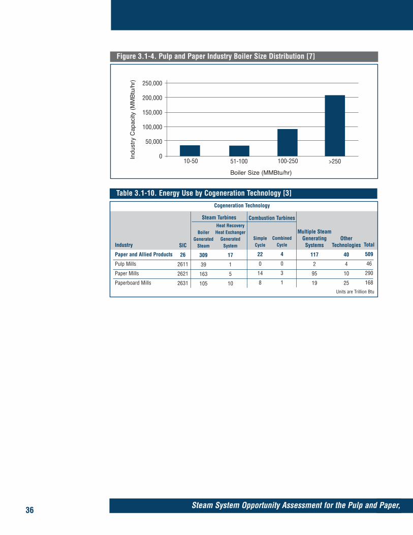
36 Steam System Opportunity Assessment for the Pulp and Paper,
Table 3.1-10. Energy Use by Cogeneration Technology [3]
Industry
Paper and Allied Products
Pulp Mills
Paper Mills
Paperboard Mills
BoilerGenerated
Steam
309
39
163
105
CombinedCycle
4
0
3
1
OtherTechnologies
40
4
10
25
Cogeneration Technology
SIC
26
2611
2621
2631
Heat RecoveryHeat Exchanger
GeneratedSystem
17
1
5
10
SimpleCycle
22
0
14
8
Multiple SteamGenerating
Systems
117
2
95
19
Total
509
46
290
168
Steam Turbines Combustion Turbines
Units are Trillion Btu
Figure 3.1-4. Pulp and Paper Industry Boiler Size Distribution [7]
Indu
stry
Cap
acity
(M
MB
tu/h
r)
Boiler Size (MMBtu/hr)
>250100-25010-50
250,000
200,000
150,000
100,000
50,000
051-100

37Chemical Manufacturing, and Petroleum Refining Industries
3.2 Assessing Steam Use in the Chemical Manufacturing IndustryFigures and Tables referenced in this section begin on page 46 in the order they are men-tioned in the text.
Introduction The chemical manufacturing industry uses a significant amount of energy to man-ufacture chemical products for consumer and industrial markets. However, theprocesses used by chemical manufacturers to produce these products are typicallyconsidered competitive information, making it difficult to assess energy use in thisindustry from a process perspective. Consequently, a different approach to assess-ing chemical industry steam generation and use is required. Because a relativelysmall number of chemical products account for most of the industry’s energy use,evaluating these high energy-use chemical products can provide a reasonablyaccurate assessment of how energy, specifically steam energy, is used.
Key ResultsThe chemical industry produces over 70,000 products [1]. In 1994, the chemicalindustry used about 3,273 trillion Btu of energy, of which steam energy accountsfor roughly 1,540 trillion Btu (see Section 2). Within the chemical industry (SIC 28),there are nine 4-digit SIC segments that account for 1,210 trillion Btu (see Section2) of fuel used to generate steam, which is approximately 79 percent of the indus-try total. Within these nine SIC segments, there are 20 chemical products whoseprocess steam energy requirements account for 832 trillion Btu of steam.
The estimated steam energy requirements for these 20 major chemicals are shownin Figure 3.2-1. The steam energy requirements for these 20 products variedbetween 0.3 and 343 trillion Btu.
Using a 75 percent conversion efficiency, which accounts for losses in convert-ing fuel to thermal energy, generating steam and delivering it to the end uses, the 832 trillion Btu of steam energy translates to 1,109 trillion Btu of fuel energy.Consequently, evaluation of the process energy requirements of these 20 chemicalproducts accounts for 90 percent of the steam use within the nine selected SICs and71 percent of the total industry steam use.
The sources of steam in the chemical manufacturing industry include boilers andprocess heat recovery heat exchangers. The estimated boiler capacity in the chemi-cal manufacturing industry is about 500,000 MMBtu/hr. Over half of this capacity,about 280 MMBtu/hr, is accounted for by boilers above 100 MMBtu/hr. However,small boilers between 10 and 50 MMBtu/hr account for about 120,000 MMBtu/hrof industry capacity, illustrating the wide distribution of boiler size across theindustry. Natural gas is the dominant fuel type, accounting for about 205,000MMBtu/hr of industry boiler capacity. About 60 percent of the boiler capacity liesin the pressure range between 300 and 1,000 psig.
General Applications of Steam in the Chemical IndustryChemical manufacturers use steam for many purposes, including:
• Stripping• Fractionation• Power generation• Mechanical drive• Quenching• Dilution

• Process heating• Vacuum draw• Pressure regulation• Injection• Source of process water.
StrippingSteam is often used to facilitate the separation of components. In stripping towers,steam pulls unwanted contaminants from a process fluid. The steam used in theseapplications is not directly returned because the effluent has too many unwantedsubstances.
FractionationIn fractionating towers, steam is used to assist in the separation of chemical prod-ucts that contain components with different boiling points. Steam is injected in thebottom of these towers along with a feedstock. The steam helps carry the morevolatile products up the tower where they condense on trays that are maintainedat the condensation temperature of the desired products. The steam provides amass transport medium, helps prevent deposition on hot surfaces, and providesfavorable viscosity properties of the product within the tower.
Power GenerationIn power generation, steam is often used to drive turbines, which, in turn, spinelectric generators. Many chemical plants meet their electric power needs with amixture of purchased power and on-site generation. The ratio between purchasedpower and self-generated power depends on several factors, including cost of elec-tricity, availability, and capacity of on-site power generation, and on-site demandfor steam.
Mechanical DriveIn many chemical manufacturing facilities, most mechanical drive energy—about340 trillion Btu—is supplied by electric power; however, steam and natural gasaccount for a large portion of this energy component, roughly 39 trillion Btu [2].
38 Steam System Opportunity Assessment for the Pulp and Paper,
A relatively small number of chemical products accounts
for most of the industry’s steamenergy use. The 832 trillion Btu
of steam energy equates to 1,109 trillion Btu of fuel energy.

Section 3.2
39Chemical Manufacturing, and Petroleum Refining Industries
Steam is used because of its reliability, availability, and favorable economic feasi-bility under certain conditions. Because either a turbine or a motor can equallyserve many processes, deciding which option to use is typically based on relativeeconomic advantages. Important factors are the cost of steam and net electricityprice (accounting for both energy and demand charges). In many critical applica-tions, plants incorporate redundancy by installing both types of drives, thus pre-venting a failure in one power source from causing a costly shutdown.
The chemical products whose production require the largest amount of mechanicaldrive energy are ethylene, ammonia, and organic resins, such as polyethylene andpolypropylene. The industry segments that correspond to these products accountfor 36 trillion Btu of the 39 trillion Btu used in mechanical drive applications.
Process HeatingSteam is used in many chemical process heating applications. Favorable steamcharacteristics for these applications include:
• Constant temperature heat delivery• Effective temperature control through regulation of the steam pressure• Large heat content per unit mass.
Steam provides an excellent heat source for applications that require temperaturesbetween 250° and 500°F. Competing sources of process heat include direct-fired fur-naces and process fluid heat recovery heat exchangers. Although steam is used inapplications with temperatures up to 700°F, the pressure requirements for thissteam often make its generation and distribution impractical. Direct-fired furnacescan typically achieve higher temperatures than what steam can feasibly provideand are widely used in many chemical industry applications. Additionally, manychemical production processes involve exothermic reactions that provide opportu-nities for process heating with fluid-to-fluid heat exchangers.
Quenching An important part of controlling chemical reactions is the regulation of the reac-tion temperature. In many applications, steam controls process temperature byquenching. Many chemical processes involve exothermic reactions and the heatreleased affects the temperature of the reaction. Steam is often directly injected toregulate such processes. Steam has a large latent heat capacity and can often beseparated from process streams in subsequent steps, especially with chemicals thathave low solubilities in water.
Dilution In dilution, steam is often used to dilute a process gas to reduce coke formation onheat exchanger surfaces. Many chemical products, particularly hydrocarbons, tendto form deposits on high-temperature surfaces, which results in reduced heat trans-fer. Because these deposits are difficult to remove, steam is often injected with theprocess chemicals to minimize their surface formation. Steam helps by dilutingthese chemicals and by reducing localized hot spots.
Vacuum DrawSteam ejectors are often used to produce a vacuum in certain process equipment.Steam ejectors use flow through a nozzle and a diffuser to create this vacuum.Other equipment that serves this purpose includes motor-driven vacuum pumps.The amount of steam used for this purpose varies from plant to plant.

Partial Pressure ControlSteam is often used to control the partial pressure of a reaction. When steam isinjected with reactants in a fixed-volume vessel, it can increase the pressure andcause a desired shift in the reaction. This use of steam is particularly effective whenthe reactants have low solubility in water. An example of this use is found in ethyl-ene production, where steam is injected into the pyrolysis furnace to inhibitunwanted reactions such as polymerization and cyclization.
Injection Steam is often directly injected into a process to help transport products. Steameffectively serves in these applications by providing a source of pressure or by act-ing as an entrainment medium. A favorable characteristic in such applications isthe ability to separate the water from the product in subsequent steps.
Source of WaterSteam is also a source of water as a solvent and a feedstock. As a solvent, steamprovides both heat and solubility. As a feedstock, steam provides a source of pres-sure, temperature, and hydrogen (e.g., as in steam methane reforming).
Steam Use in the Chemical Industry by ProductTo estimate the steam energy use in the chemical industry, the 20 most energy-intensive chemical products were evaluated. For these products, Table 3.2-1 showsthe production amounts, the steam energy requirements per pound, and the totalamount of steam needed to meet this production. Table 3.2-1 also indicates thetotal energy required to produce these products to indicate the amount of steamportion. The chemicals and the processes that account for their steam requirementsare discussed below.
Ethylene ManufactureEthylene accounts for almost 25 percent of total chemical industry steam use. In1994, over 22 million tons of ethylene were produced with about 343 trillion Btu ofsteam used to support this production, as shown in Table 3.2-2. Ethylene is one ofthe more important chemicals produced because of its use as a feedstock for a widerange of other products, including polyethylene, polyvinyl chloride, ethylene gly-col, and various solvents and paints [1,3].
Ethylene is manufactured from the pyrolysis of a hydrocarbon feedstock. Commonfeedstocks include naphtha, ethane, and gas oil. Because ethylene productionrequires an abundant supply of hydrocarbon feedstock, ethylene plants are usuallylocated near refineries. Although the pyrolysis reaction occurs in a direct-fired fur-nace, steam is also important to ethylene production. Steam is injected in thepyrolysis furnace both to dilute and to lower the partial pressure of the feedstock.Dilution helps inhibit the formation of coke on the furnace surfaces. Reducing thepartial pressure of the feedstock helps drive the reaction toward ethylene produc-tion and away from undesired secondary reactions. Pyrolysis occurs at tempera-tures between 1,400° and 1,600°F, and unless reaction conditions are properlymaintained, unwanted reactions such as polymerization and cyclization will result.
The amount of steam injected in the pyrolysis furnace depends on the feedstock.Where ethane is the dominant feedstock component, the amount of steam used isroughly 1/3 lb per lb of feedstock. However, with heavier feedstocks, there is anincreased tendency for coke formation; feedstocks such as gas oil require a steamfeed of about 3 lbs per lb of feedstock. Even within the same density of feedstock, thesteam requirement varies depending on other factors that affect the pyrolysis reaction.
40 Steam System Opportunity Assessment for the Pulp and Paper,

Section 3.2
41Chemical Manufacturing, and Petroleum Refining Industries
In ethylene production, steam is both provided to the process and recovered fromthe pyrolysis reaction, which is exothermic. Steam is also used in stripping andfractionating processes. Ethylene production uses a large amount of mechanicaldrive energy. According to MECS, about 68 trillion Btu of energy is used inmachine drive applications for this industry segment and steam accounts for about28 trillion Btu of this energy component.
Ammonia ManufactureAmmonia is primarily manufactured by combining hydrogen with nitrogen in thepresence of an iron catalyst. The nitrogen is supplied by air while the hydrogen istypically obtained from a process that combines high pressure steam with naturalgas in the presence of a catalyst, a process known as steam methane reforming(SMR). Because natural gas is primarily methane (CH4) it contains a large amountof hydrogen. Reforming releases much of the hydrogen in the steam. SMR oftenoccurs in two stages that have different sets of temperatures, catalyst reactions andrelative amounts of feedstock and steam. The SMR process is an important use ofsteam for other industries as well, including petroleum refining.
Other uses of steam in ammonia manufacturing include stripping unwanted gasesfrom the product and facilitating ammonia conversion, as described in Table 3.2-3.
UreaUrea is made primarily from ammonia. Combining ammonia with carbon dioxideat high pressures (between 2,000 and 3,700 psig) and high temperatures (350° to450°F), generates a urea solution. Depending on the requirements of the finalproduct, the urea can either be concentrated and formed into solid pellets or soldas a liquid solution. In urea production, steam is primarily used for process heat-ing in the reaction vessel, as described in Table 3.2-4.
Styrene and Ethylbenzene ManufactureStyrene and ethylbenzene are closely linked because ethylbenzene is a feedstock forthe production of styrene. Approximately 99 percent of ethylbenzene is used toproduce styrene. Ethylbenzene itself is made from ethylene and benzene through aseries of catalytic reactions. Although ethylbenzene production is exothermic,steam is used to support several distillation tasks, as described in Table 3.2-5.
In contrast, styrene production is highly energy intensive. Although some styrene ismanufactured as a byproduct of propylene oxide, most styrene is made by combin-ing steam and ethylbenzene. Superheated steam is combined with ethylbenzene inthe presence of a catalyst to remove hydrogen from (dehydrogenate) the ethylben-zene. The output of this process is sent to a distilling tower where additional steamfacilitates the separation of styrene from the remaining ethylbenzene. The ethyl-benzene is recycled back into the process, while the styrene is recovered.
PolystyrenePolystyrene is the polymerized form of styrene. To begin the polymerization reac-tion, a feedstock of styrene is heated to approximately 230°F. After some of thestyrene has polymerized, the solution is sent into a reaction tower, where the solu-tion is agitated, mixed with additives, and maintained at a temperature usuallybetween 230° and 350°F. Various desired properties of the final product, such asmolecular weight, are achieved by controlling certain reaction parameters. Thepolymerized mixture is then sent to processing equipment that converts the poly-styrene into pellets or strands. Steam use in polystyrene production is described inTable 3.2-6.

Chlorine and Sodium Hydroxide ManufactureChlorine and sodium hydroxide are manufactured as coproducts from the sameprocess. These chemicals are primarily produced by the electrolysis of brine. In thisprocess, the brine is introduced into an electric field with the negative and positivepoles separated by a semipermeable diaphragm. The chlorine collects as a gas atthe positive pole. At the negative pole, sodium ions collect and the solutionbecomes sodium hydroxide (caustic soda). Hydrogen is offgassed at the negative pole.
Steam use, as described in Table 3.2-7, has several applications during chlorine/sodium hydroxide production:
• To increase the concentration of the caustic soda solution• To preheat the brine prior to electrolysis• To strip contaminants• To provide thermal energy in the evaporator to achieve the appropriate con-
centration of caustic soda. (Concentrating the caustic solution is performed ineither single or multiple effect evaporators.)
Ethylene Dichloride/PVC Manufacture Ethylene dichloride is a feedstock for polyvinyl chloride (PVC). Approximately 98 percent of ethylene dichloride production is used to manufacture vinyl chloridemonomer, which, in turn, is used to produce PVC. The production of ethylenedichloride combines ethylene and chlorine in the presence of a catalyst, creating aslightly exothermic reaction. In the production of ethylene dichloride, steam is pri-marily used to strip the waste products.
Ethylene dichloride is then sent on to produce vinyl chloride monomer. Ethylenedichloride is heated in a furnace through steam injection to initiate cracking, thuscreating several products including vinyl chloride monomer and hydrochloric acid.Steam is injected into the furnace to facilitate the reaction. The products from thefurnace are quenched, distilled, and separated. The hydrochloric acid is recoveredand the vinyl chloride monomer is sent on as a feedstock for other processes,including PVC production.
PVC is manufactured by polymerizing the vinyl chloride monomer in a heatedreaction vessel that has agitation devices to facilitate the process. Because the prod-uct from the reaction vessel contains unwanted components, such as unreactedvinyl chloride monomer, steam is used to strip the product. After stripping, the PVCis dewatered in a centrifuge and then dried further in a heat exchanger.
In the production of ethylene dichloride and PVC, steam is used in several processheating tasks and in stripping contaminants, as described in Table 3.2-8.
Phenol/Acetone ManufacturePhenol is produced from a feedstock of cumene, which in turn is manufacturedfrom propylene. To produce phenol, cumene is reacted with air at approximately220°F to form an oxidized product, which is then sent through a separator and aconcentrator. Steam is used in the concentrator to remove gases and other unwant-ed products.
The output of the concentrator is sent through a series of purification steps that iso-late the phenol and acetone. Steam is used in this process to facilitate the separa-tion of components in fractionating towers, as described in Table 3.2-9.
42 Steam System Opportunity Assessment for the Pulp and Paper,
Section 3.2
43Chemical Manufacturing, and Petroleum Refining Industries
Benzene, Toluene, and Xylenes (BTXs)Benzene, toluene, and xylenes are similar products that are frequently referred tocollectively as BTXs. Benzene accounts for most BTX production. Approximately 80 percent of benzene is produced from reformed naphtha or pyrolysis gas. In thenaphtha process, naphtha is exposed to a catalyst that converts it into a mixtureof BTX compounds. Where pyrolysis gas is used, the feedstock already containsBTX compounds, but it is necessary to separate these components.
Separation processes start with solvent extraction to pull the BTX compounds outof the other components. The BTX-rich solvent is then sent to a fractionating columnwhere the BTXs and the solvent are separated. The solvent is returned to the upstreamseparation process and the BTXs are sent to a series of towers that fractionate theindividual benzene, toluene, and xylene components. Steam is used in the fraction-ating towers to facilitate component separation, as described in Table 3.2-10.
CaprolactumAbout 80 percent of caprolactum production is used as a feedstock to producenylons. The remaining 20 percent of caprolactum production is used in engineer-ing resins and films. The feedstock for caprolactum is cyclohexanone, which itselfis made from cyclohexane. Cyclohexanone undergoes a series of catalyst-basedchemical reactions and the product is then combined with ammonia. Addingammonia generates caprolactum and other byproducts such as ammonium nitrateand ammonium phosphate, commonly sold for fertilizer production. Steam use incaprolactum production is described in Table 3.2-11.
Sodium CarbonateSodium carbonate, also known as soda ash, is used in several applications includ-ing glass manufacturing and as a feedstock for several cleaning agents. In theUnited States soda ash is produced from trona ore, which is a complex of severalcomponents, including sodium and carbon. There are two principal ways in whichtrona ore is extracted from the ground that affect the way sodium carbonate is iso-lated. In one extraction method, sodium hydroxide is used to dissolve the tronaore. The resulting solution must be treated to precipitate out the sodium carbonate.Steam is primarily used to facilitate the precipitation processes. Because some ofthe precipitation processes are performed under vacuum, steam is used to pull thisvacuum and to provide process heating, as described in Table 3.2-12.
Another ore extraction method uses blasting, which results in the recovery of solidtrona that must be crushed, dissolved, filtered, and then processed to isolate thesodium carbonate. In both extraction methods, calcining is required. Calcining is adirect-fired process that is usually performed in a furnace.
Synthetic RubbersThere are three principal synthetic rubber products: polybutadiene rubber, styrenebutadiene rubber (SBR), and butyl rubber. Polybutadiene rubber (PBR) is used intires, footwear, wire insulation, and conveyor belts. The production of PBR accountsfor roughly 10 trillion Btu in steam energy. The steam requirements for PBR areshown in Table 3.2-13.
SBR is widely used in tires, carpet backing, flooring, wire and cable insulation, andfootwear. SBR production accounts for about 7 trillion Btu in steam energy. Thesteam requirements for SBR are shown in Table 3.2-14.

44 Steam System Opportunity Assessment for the Pulp and Paper,
Butyl rubber is also used in tires; however, because of its excellent air retention, it isthe preferred material for inner tubes. It is also used in the inner liners of tubelesstires, and for many other automobile components, such as window strips, becauseof its resistance to oxidation. The steam requirements for butyl rubber productionare shown in Table 3.2-15.
CyclohexaneCyclohexane is an important chemical in the production of adipic acid, which inturn is used to produce nylons and various adhesives, and as a flue gas desulfuriza-tion agent for coal-fired power plants. Cyclohexane is produced by combining ben-zene with hydrogen in the presence of heat and a catalyst. Steam is used to preheatthe reactants and to stabilize the final products, as shown in Table 3.2-16.
Sources of Steam GenerationThe primary sources of steam generation are boilers and process heat recovery heatexchangers. Boilers use the combustion of fossil fuels to produce the thermal energythat is used to generate steam. Heat recovery steam generators rely on heat transferfrom a high-temperature process fluid to generate steam.
Heat RecoveryThere are many sources of heat recovery in chemical manufacturing. Some reac-tions require high temperatures, allowing the use of process fluids to transfer heatto other processes and to generate steam. Additionally, many chemical processesare exothermic and heat recovery is used both to moderate the reaction tempera-ture and to utilize useful energy within the plant.
The amount of steam generated from process heat recovery varies widely across theindustry because of the diversity of chemical processes. Also, the amount of steamgenerated varies within industry segments and from plant to plant depending onfacility size, age, level of manufacturing integration, and range of products pro-duced at the plant.
BoilersThe estimated boiler capacity in the chemical manufacturing industry is about500,000 MMBtu/hr. Figure 3.2-2 shows boiler capacity distribution according toboiler size. Over half of this capacity, about 280 MMBtu/hr, is accounted for byboilers above 100 MMBtu/hr. However, small boilers between 10 and 50 MMBtu/hraccount for about 120,000 MMBtu/hr, illustrating the wide distribution of boilersize across the industry. This distribution is consistent with the range of diverseplant sizes and steam needs in the chemical industry.
Similarly, several different fuel types account for much of the boiler capacity. Figure3.2-3 shows boiler capacity by fuel type. Natural gas, the dominant fuel type,accounts for about 205,000 MMBtu/hr of chemical industry boiler capacity, largelybecause it is used as a feedstock in many industry applications. As a result, manylarge chemical facilities are located close to natural gas supplies.
With respect to pressure, the largest amount of steam system capacity—over300,000 MMBtu/hr—falls between 300 and 1,000 psig, as shown in Figure 3.2-4.Steam system pressures higher than 1,000 psig account for just over 25,000MMBtu/hr, or 5 percent, of total steam system capacity.

Section 3.2
45Chemical Manufacturing, and Petroleum Refining Industries
CogenerationSteam is generated in cogeneration systems by two principal methods.
• Steam is generated by boilers then, depending on the system configuration,some or all of the steam is sent to drive steam turbines connected to electricgenerators. In some systems, the steam is exhausted from backpressure tur-bines into a header and used in other applications. In other systems, thesteam is delivered to turbines, condensed, and sent into the condensate sys-tem, while the remaining boiler-generated steam is sent directly to processapplications.
• Steam is generated by the waste heat recovered from reciprocating engines orgas turbines that are used to drive electric generators.
Many plants have both types of cogeneration capabilities. In fact, in the chemicalindustry, most of the electric energy—about 343 trillion Btu—is cogenerated frommultiple technology systems. An example of this is the use of boiler-supplied steamto drive a steam turbine that is connected to an electric generator while also gener-ating steam with heat recovery steam generators. These steam generators mayrecover heat from process fluids or from the exhaust gases of combustion turbines.These plants usually combine steam boilers, heat recovery heat exchangers, and,in many cases, combustion turbines. The relative balance between these sourcesdepends on many plant characteristics, including fuel cost, electric energy prices,and the relation between thermal and electric energy requirements. Table 3.2-17illustrates the amount of fuel used by the chemical industry in cogeneration appli-cations.
References:
[1] Energy and Environmental Profile of the U.S. Chemical Industry, U.S. Departmentof Energy, Office of Industrial Technologies, May 2000.
[2] Manufacturing Energy Consumption Survey 1994 (MECS), U.S. Department ofEnergy, Energy Information Administration, 1997.
[3] U.S. Chemical Industry Statistical Handbook 1999, Chemical ManufacturersAssociation, 1999.
[4] Energy Analysis of 108 Industrial Processes, Drexel University Project Team;Brown, H.; Hamel, B.; Fairmont Press, 1985.
[5] 1992 Industrial Process Heat Energy Analysis, Final Report No. GRI 96/0353,Gas Research Institute, September 1996.
[6] Major Industrial Plant Database (MIPDTM), IHS Energy, June 1999.
[7] Analysis of the Industrial Boiler Population, Final Report No. GRI-96/0200, GasTechnology Institute, June 1996.

46 Steam System Opportunity Assessment for the Pulp and Paper,
Table 3.2-1. Leading Energy-Intensive Chemicals [1,3,4]
Chemical
Ethylene
Ammonia
Ethylbenzene/Styrene
Polystyrene
Chlorine/Sodium Hydroxide
Ethylene Dichloride/Polyvinyl Chloride
Phenol/Acetone
Benzene, Toluene, and Xylene
Caprolactum
Sodium Carbonate
Urea
Polybutadiene Rubber
Styrene Butadiene Rubber
Butyl Rubber
Cyclohexane
Production(Million lbs)
44,534
15,788
11,270
7,620
25,078
14,818
4,054
28,118
1,508
20,552
16,720
550
2,497
431
2,108
Total Energy(Trillion Btu)
406
274
190
17
197
34
32
12
18
79
18
10
7
7
4
1,305
SIC
2869
2873
2865
2821
2812
2821
2865
2865
2824
2812
2873
2822
2822
2822
2865
Unit SteamEnergy (Btu/lb)
7,695
5,062
15,000
2,123
2,909
1,648
7,459
342
9,691
2,683
483
1,584
2,049
638
1,593
Totals
Total SteamEnergy
(Trillion Btu)
343
80
169
16
73
24
30
10
15
55
8
0.9
5
0.3
3
832
Figure 3.2-1. Estimated Steam Energy Use for 20 Major Chemical Products
Cyclohexane
Butyl Rubber
Styrene Butadiene Rubber
Polybutadiene Rubber
Urea
Sodium Carbonate
Caprolactum
Benzene, Toluene, and Xylene
Phenol/Acetone
Ethylene Dichloride/Polyvinyl Chloride
Chlorine/Sodium Hydroxide
Polystyrene
Ethylbenzene/Styrene
Ammonia
Ethylene
0 100 200 300
Trillion Btu
400

Section 3.2
47Chemical Manufacturing, and Petroleum Refining Industries
Table 3.2-2. Energy Use in Ethylene Production [1,3,4,5]
Process
Dilution
Acetylene Removal (Stripping)
Fractionation
Mechanical Drive (Process Steam)
Mechanical Drive (Recovered Steam)
SteamTemperature
(°F)
350
250
300
600
600
Total
Total Energy(Trillion Btu)
406
SteamPressure
(psig)
120
15
50
1,000
1,000
Unit SteamUse (Btu/lb)
2,467
253
675
629
3,671
7,695
Total SteamEnergy
(Trillion Btu)
343
Production(Million lbs)
44,534
Steam Energyas a % of
Total
85%
Table 3.2-4. Energy Use in Urea Production [1,3,4,5]
Process
Synthesis Reaction
SteamTemperature
(°F)
375
Total Energy(Trillion Btu)
18
SteamPressure
(psig)
170
Unit SteamUse
(Btu/lb)
483
Total SteamEnergy
(Trillion Btu)
8
Production(Million lbs)
16,720
Steam Energyas a % of
Total
45%
Table 3.2-3. Energy Use in Ammonia Production [1,3,4,5]
Process
Steam Reformer
Other Processes (Stripping,Additional Conversion Steps)
SteamTemperature
(°F)
475
Various
Total Energy(Trillion Btu)
SteamPressure
(psig)
650
Various
Unit SteamUse
(Btu/lb)
2,665
2,397
Total SteamEnergy
(Trillion Btu)Production
(Million lbs)
Steam Energyas a % of
Total
Table 3.2-5. Energy Use in Ethylbenzene/Styrene Production [1,3,4,5]
Process
Benzene Distillation
Benzene Drying
Ethylbenzene Distillation
Ethylbenzene Preheating
Dehydrogenation Reactor
Superheater
Steam Preheat
Separation
Fractionation
Ethylbenzene Distillation
Styrene Distillation
SteamTemperature
(°F)
320
350
400
350
1,200
750
380
230
300
230
230
Total
Total Energy(Trillion Btu)
190
SteamPressure
(psig)
75
120
235
120
Vacuum
Various
180
5
50
5
5
Unit SteamUse (Btu/lb)
265
182
338
370
4,922
4,037
3,433
234
73
755
390
15,000
Total SteamEnergy
(Trillion Btu)
169
Production(Million lbs)
11,270
Steam Energyas a % of
Total
89%
Total 5,062 15,738 80 274 29%

48 Steam System Opportunity Assessment for the Pulp and Paper,
Table 3.2-6. Energy Use in Polystyrene Production [1,3,4,5]
Process
Condenser
Blending
Melt Compounding
Drying
SteamTemperature
(°F)
250
250
525
370
Total
Total Energy(Trillion Btu)
17
SteamPressure
(psig)
15
15
850
160
Unit SteamUse
(Btu/lb)
118
391
1,212
402
2,123
Total SteamEnergy
(Trillion Btu)
16
Production(Million lbs)
7,620
Steam Energyas a % of
Total
94%
Table 3.2-7. Energy Use in Chlorine/Sodium Hydroxide Production [1,3,4,5]
Process
First Brine Heater
Second Brine Heater
Cooler/Stripper
Multiple Evaporator
Evaporator
SteamTemperature
(°F)
350
350
350
350
350
Total
Total Energy(Trillion Btu)
197
SteamPressure
(psig)
120
120
120
120
120
Unit SteamUse
(Btu/lb)
375
225
62
1,748
499
2,909
Total SteamEnergy
(Trillion Btu)
73
Production(Million lbs)
25,078
Steam Energyas a % of
Total
37%
Table 3.2-8. Energy Use in Ethylene Dichloride/PVC Production [1,3,4,5]
Process
Vinyl Chloride Production
Reactor
Dumping Tank
Distillation
Drying
Blending
Melt Compounding
Drying
SteamTemperature
(°F)
250
250
250
250
370
250
295
370
Total
Total Energy(Trillion Btu)
34
SteamPressure
(psig)
15
15
15
15
160
15
50
160
Unit SteamUse
(Btu/lb)
658
292
65
5
333
65
164
67
1,648
Total SteamEnergy
(Trillion Btu)
24
Production(Million lbs)
14,818
Steam Energyas a % of
Total
71%
Table 3.2-9. Energy Use in Phenol/Acetone Production [1,3,4,5]
Process
Depropanizer
Benzene Column
Cumene Column
Concentrator
Acetone Column
Vacuum Column
Phenol Column
SteamTemperature
(°F)
240
460
500
250
250
250
250
Total
Total Energy(Trillion Btu)
32
SteamPressure
(psig)
10
450
665
15
15
15
15
Unit SteamUse
(Btu/lb)
152
1,371
189
696
889
3,124
1,038
7,459
Total SteamEnergy
(Trillion Btu)
30
Production(Million lbs)
4,054
Steam Energyas a % of
Total
95%

Section 3.2
49Chemical Manufacturing, and Petroleum Refining Industries
Table 3.2-10. Energy Use in Benzene, Toluene, and Xylene Production [1,3,4,5]
Process
Solvent Recovery
Fractionation
SteamTemperature
(°F)
250
250
Total
Total Energy(Trillion Btu)
12
SteamPressure
(psig)
20
20
Unit SteamUse
(Btu/lb)
171
171
342
Total SteamEnergy
(Trillion Btu)
10
Production(Million lbs)
28,118
Steam Energyas a % of
Total
81%
Table 3.2-11. Energy Use in Caprolactum Production [1,3,4,5]
Process
Various Reactions
SteamTemperature
(°F)
Various
Total Energy(Trillion Btu)
18
SteamPressure
(psig)
Various
Unit SteamUse
(Btu/lb)
9,691
Total SteamEnergy
(Trillion Btu)
14.6
Production(Million lbs)
1,508
Steam Energyas a % of
Total
81%
Table 3.2-12. Energy Use in Sodium Carbonate Production [1,3,4,5]
Process
Vacuum Crystalizer
SteamTemperature
(°F)
250
Total Energy(Trillion Btu)
79
SteamPressure
(psig)
15
Unit SteamUse
(Btu/lb)
2,683
Total SteamEnergy
(Trillion Btu)
55
Production(Million lbs)
20,552
Steam Energyas a % of
Total
70%
Table 3.2-14. Energy Use in Styrene Butadiene Rubber Production [1,3,4,5]
Process
Bulk Storage
Monomer and Solvent Stripper
Monomer and Solvent Separator
Hot Emulsion Reactor
Latex Stripper
Latex Concentrator
Thermal Drying
SteamTemperature
(°F)
250
250
250
250
250
250
250
Total
Total Energy(Trillion Btu)
7
SteamPressure
(psig)
15
15
15
15
15
15
15
Unit SteamUse
(Btu/lb)
54
121
30
472
605
242
525
2,049
Total SteamEnergy
(Trillion Btu)
5
Production(Million lbs)
2,497
Steam Energyas a % of
Total
73%
Table 3.2-13. Energy Use in Polybutadiene Rubber Production [1,3,4,5]
Process
Mixer
Blowdown Tank
SteamTemperature
(°F)
250
250
Total
Total Energy(Trillion Btu)
10
SteamPressure
(psig)
15
15
Unit SteamUse
(Btu/lb)
478
1,106
1,584
Total SteamEnergy
(Trillion Btu)
0.9
Production(Million lbs)
550
Steam Energyas a % of
Total
9%

50 Steam System Opportunity Assessment for the Pulp and Paper,
Figure 3.2-3. Chemical Industry Boiler Capacity by Fuel Type [7]
Indu
stry
Cap
acity
(M
MB
tu/h
r)
Fuel TypeOtherCoalGas
250,000
200,000
150,000
100,000
50,000
0Oil
Table 3.2-16. Energy Use in Cyclohexane Production [1,3,4,5]
Process
Preheater
Stabilizer
SteamTemperature
(°F)
489
489
Total
Total Energy(Trillion Btu)
4
SteamPressure
(psig)
600
600
Unit SteamUse
(Btu/lb)
1,247
346
1,593
Total SteamEnergy
(Trillion Btu)
3.4
Production(Million lbs)
2,108
Steam Energyas a % of
Total
91%
Figure 3.2-2. Chemical Industry Boiler Capacity by Boiler Size [7]
Indu
stry
Cap
acity
(M
MB
tu/h
r)
Boiler Size (MMBtu/hr)
>250100-25010-50
160,000
140,000
120,000
100,000
80,000
60,000
40,000
20,000
051-100
Table 3.2-15. Energy Use in Butyl Rubber Production [1,3,4,5]
Process
Distillation Tower
Distillation Tower
Extruder
SteamTemperature
(°F)
250
250
250
Total
Total Energy(Trillion Btu)
7
SteamPressure
(psig)
15
15
15
Total SteamEnergy
(Trillion Btu)
0.3
Production(Million lbs)
431
Steam Energyas a % of
Total
4%
Unit SteamUse
(Btu/lb)
150
100
388
638

Section 3.2
51Chemical Manufacturing, and Petroleum Refining Industries
Figure 3.2-4. Chemical Industry Steam System Capacity by Pressure [6,7]In
dust
ry C
apac
ity (
MM
Btu
/hr)
Pressure (psig)>1000<300
350,000
300,000
250,000
200,000
150,000
100,000
50,000
0300-1000
Table 3.2-17. Cogeneration Fuel Use in the Chemical Industry [2]
Industry
Chemicals and Allied Products
Alkalies
Inorganic Pigments
Industrial Inorganic Chemicals, nec.*
Plastics Materials & Resins
Synthetic Rubber
Organic Fibers, Noncellulosic
Cyclic Crudes and Intermediates
Industrial Organic Chemicals, nec.*
Nitrogenous Fertilizers
*Not elsewhere classified
SteamSupplied by
Boilers
46
18
0
10
2
2
7
0
7
0
MultipleTechnologies
343
84
0
0
30
0
7
7
211
4
Other
6
0
0
4
0
0
0
0
0
0
Cogeneration Technology
SIC
28
2812
2816
2819
2821
2822
2824
2865
2869
2873
Steam Supplied byHeat Recovery
Heat Exchangers
17
0
0
8
0
0
0
0
9
0
CombustionTurbines
29
0
0
4
14
0
0
0
9
2
Total
442
102
0
26
46
2
14
8
235
7
Steam Turbines
Units are Trillion Btu

3.3 Assessing Steam Use in the Petroleum Refining IndustryFigures and Tables referenced in this section begin on page 62 in the order they are men-tioned in the text.
Introduction The petroleum refining industry uses energy to convert crude oil into many differ-ent products, some of which are used directly by consumers, while others are feed-stocks for other industries. Production data for these petroleum refining processescan be combined with process energy data to estimate overall industry energy use.Additionally, the component energy types, including direct-fired, electric, andsteam, can be disaggregated from the energy data for each refining process. Thisallocation allows the total steam use within the industry to be estimated. Thissteam use estimate can then be compared to the amount of fuel used to generatesteam, as indicated by the Manufacturing Energy Consumption Survey 1994 (MECS) [1].
This section describes energy data for steam use by key end-use processes. This sec-tion also describes how steam is used by the major refining processes and discussessources of steam generation.
Key ResultsThere are 11 major refining processes that represent the principal end uses of steamin the petroleum refining industry. The estimated steam energy requirements formajor petroleum refining processes are presented in Figure 3.3-1. Process steamenergy-use requirements vary between 12.4 and 261.4 trillion Btu. Note that vis-
breaking and coking operations are netsteam producers.
The sum of the energy use for these 11process is 900 trillion Btu. If a steamsystem efficiency of 75 percent isassumed, the total fuel used to generatesteam based on the process databecomes 1,200 (= 900/0.75) trillion Btu.Section 2 of this report estimated thatthe petroleum industry used 1,675 tril-lion Btu for steam generation. Thesetwo estimates of fuel used to generatesteam in the petroleum refining indus-try compare favorably.
The major sources of steam generationin the petroleum refining industry areboilers and heat recovery steam gener-ators. The estimated boiler capacity inthe refining industry is about 210,000MMBtu/hr. Boilers that generate morethan 250 MMBtu/hr account for about100,000 MMBtu/hr, or roughly 48 per-cent of the industry’s total boiler capac-ity. Most of the boiler capacity in thepetroleum refining industry is fired bybyproduct fuels, such as refinery gasand coke. In terms of steam systempressure, about 60 percent of the total
52 Steam System Opportunity Assessment for the Pulp and Paper,
There are 11 major processesthat represent steam end
use in the petroleum refiningindustry. Steam generationfor these processes accountfor more than 1,675 trillion
Btu in fuel use.

Section 3.3
53Chemical Manufacturing, and Petroleum Refining Industries
industry boiler capacity is at 300 psig or less. Most of the remaining boiler capacityis between 300 and 1,000 psig.
Steam Use in the Petroleum Refining Industry by Major ProcessesCombining the energy used by each process and the amount of product producedby each process provides an estimate of the total amount of energy used by theindustry. This energy use can be disaggregated into components of electric, direct-fired, and steam energy. Table 3.3-1 describes the average energy requirements ofthese processes by technology and combines production estimates to calculate over-all industry energy use. In 1994, total energy used by the processes in the petrole-um refining industry is estimated as 2,333 trillion Btu, of which steam represents 900 trillion Btu.
The data in Table 3.3-1 represents an end use perspective. The fuel use that corre-sponds to this end-use energy data must be determined using a reasonable conver-sion factor that essentially accounts for the losses associated with converting thefuel to useful energy and delivering it. If a steam system efficiency of 75 percent isassumed, the total fuel used to generate steam based on the process data becomes1,200 (= 900/0.75) trillion Btu.
Section 2 of this report estimated that the petroleum industry used 1,675 trillionBtu for steam generation. These two estimates of fuel used to generate steam in thepetroleum refining industry compare favorably.
Similarly, in relative terms, the end-use perspective indicates that steam represents39 percent (= 900/2,333) of the total energy use, while MECS indicates that the fuelused to generate steam represents 51 percent of the total industry fuel use.
General Applications of Steam in Petroleum RefiningRefineries use steam for several purposes:
• Stripping• Fractionation• Power generation• Mechanical drive• Quenching• Dilution• Process heating• Vacuum draw.
StrippingSteam is commonly used in petroleum refining to facilitate the separation of compo-nents. In stripping towers, steam is injected with hot crude oil and carries out contami-nants such as sulfur and ammonia in a waste effluent. The steam used in stripping isusually not recovered; however, the wastewater effluent may undergo a concentrationprocess that often uses steam for process heating to reduce the volume of waste.
FractionationIn fractionating towers, steam is used to assist in the separation of hydrocarboncomponents. Steam is injected in the bottom of the tower. When steam is intro-duced with a hydrocarbon mixture, it reduces the partial pressure of the hydrocar-bon components, which facilitates the separation and removal of the volatile com-ponents. The steam helps separate the lighter hydrocarbon products, which thenrise up the tower where they condense on horizontal trays. These trays are increas-

54 Steam System Opportunity Assessment for the Pulp and Paper,
ingly cooler higher up the tower. Consequently, the heavier hydrocarbons collecton the lower trays while the lighter products collect on the higher trays. Steam alsohelps to prevent coke deposition on hot surfaces.
Power GenerationFuel use data for this report is supplied by the MECS. In MECS, there are two princi-pal categories of on-site power generation: conventional and cogeneration.Conventional generation uses fossil-fuel-fired engines or combustion turbines todrive electrical generators. Cogeneration refers to several technologies that com-bine electric power generation and thermal power use. Cogeneration includes theuse of steam turbines, which along with other steam services, use boiler generatedsteam to generate electric power. Another common type of cogeneration uses heatrecovered from the exhaust gases of an engine or a combustion turbine that drivesan electric generator. MECS provides data for conventional electric power genera-tion in terms of fuel use and cogenerated power generation in terms of kWh.
MECS indicates that the petroleum industry used about 74 trillion Btu of fuel togenerate electric power. All of this fuel was reported as natural gas. In terms ofcogeneration, about 137 trillion Btu of fuel was used by the petroleum industry tocogenerate electric and thermal power. Additional discussion of cogeneration isprovided in Section 2 of this report.
The amount of steam used in power generation applications varies widely byplant. Refining plants will usually meet their electric power needs with a mixtureof purchased power and on-site generation. The ratio between purchased powerand self-generated power depends on several factors, including cost of electricity,capacity for on-site power generation, and on-site demand for steam.
Mechanical DriveIn the petroleum refining industry, about 108 trillion Btu of energy is used inmechanical drive applications. Of this total, about 12 trillion Btu is provided bynatural gas [1]. Natural gas can be used in direct-drive applications and in firingboilers that provide steam for steam turbine-driven loads.
Steam turbines account for a large amount of energy used in machine-drive appli-cations. Steam is used because of its reliability (especially if the electric power sup-ply is prone to outage risks), and because steam turbine drives often provide favor-able economic advantages. Common examples of equipment driven by steam tur-bines include pumps and compressors. Electric motors can usually be substitutedfor steam turbines; however, the specific characteristics of the plant determinewhether a steam turbine or a motor is more feasible for certain drive applications.
Process HeatingSteam is used in many refining process heating applications; however, the amountof steam used in these applications varies. Many refining processes require temper-atures that exceed what can be reasonably met by steam. Consequently, refineriesuse significant amounts of fuel for direct-fired applications, generating this heat infurnaces and in the regenerator sections of fluid catalytic crackers.
Refineries generate significant amounts of combustible byproducts, such as refinerygas and petroleum coke, which are usually burned in either a furnace or a boiler.Refinery gas accounts for approximately 44 percent of a refinery’s energy use whilecoke comprises about 16 percent [1].

Section 3.3
55Chemical Manufacturing, and Petroleum Refining Industries
Additionally, there are many exothermic processes that are inherent to refineryoperation. These hot process streams provide many opportunities for heating needsto be served using process-to-process heat exchangers.
Quenching Another application for refinery steam is to quench hot process gases. Quenchingis one method of controlling a chemical reaction. Because many refining processesinvolve exothermic reactions, the heat released during these reactions affects thetemperature of the reaction. Steam is often injected to regulate these process tem-peratures. Steam has a large latent heat capacity and can often be separated com-paratively easily from hydrocarbon streams.
Dilution Steam is often used to dilute a process gas to reduce coke formation on heatexchanger surfaces. Hydrocarbon deposits on high temperature surfaces tend toform coke, which interferes with heat transfer. Because these deposits are difficultto remove, steam is often injected along with the oil to minimize their formation.
Pressure ControlSteam ejectors are often used to produce a vacuum in certain process equipment.Steam ejectors use flow through a nozzle and a diffuser to create this vacuum.Other equipment, such as motor-driven vacuum pumps can serve the same pur-pose. Consequently, the amount of steam used for this purpose varies from plant toplant.
Steam can also regulate the pressure of the process by being injected with a processfluid. Steam is useful in such applications because it has limited solubility withmany hydrocarbon products and can be separated out at later stages.
Description of Petroleum Refining ProcessesThe following discussion describes the principal process steps in petroleum refining.Where applicable, the use of steam to support the process is described. Figure 3.3-2provides a basic description of the process flow at a petroleum refinery.
DesaltingDesalting is the first step in the refining process. Desalting is necessary to removemetals, salts, and other contaminants that lead to equipment fouling and corro-sion and catalyst deactivation. Desalting temperatures range from 200° to 300°F.Desalting is usually electric energy intensive, relying on electric fields to attract andremove salt contaminants. Chemicals are often added to the oil to facilitate thisprocess. The energy used to heat the oil is usually provided through a process heatexchange with oil from the atmospheric distillation tower.
Atmospheric Distillation Crude oil contains a wide range of hydrocarbons. Separating hydrocarbon compo-nents by their respective boiling points produces products, such as fuel gases, lique-fied petroleum gas (LPG), gasoline, naphtha, solvents, fuel oils, coke, and petro-chemical feedstocks. Atmospheric distillation is the initial separation process and isperformed at roughly atmospheric pressure in fractionating towers. The tempera-ture of this process is kept below 725°F because at higher temperatures the hydro-carbons have enough energy to initiate a reaction known as cracking, whichresults in breakdown of long molecules into shorter ones.
In atmospheric distillation, crude oil is heated in a furnace and then sent into theflash zone of a fractionating tower. As the heated components rise within the tower

56 Steam System Opportunity Assessment for the Pulp and Paper,
they pass through openings in horizontal fractionating trays. These trays collectthe hydrocarbons that condense on them. Controlling the vapor/liquid contact inthe trays optimizes separation of the components. Light hydrocarbon gases arepulled from the top of the tower. Products such as gasoline, kerosene, and naphthaare drawn from trays in the middle of the tower. At the bottom of the tower, heavyhydrocarbon components are drawn off and sent into another distillation process.
In most fractionating towers, sidestreams are drawn off and sent to small distilla-tion columns for further separation. These fractionating towers use an additionalset of trays to separate the hydrocarbon products. The recovered steam and lightend gases are vented back into the atmospheric tower above the sidedraw tray.
Many fractionating towers use reboilers to increase the quality of the hydrocarbonseparation. Reboilers vaporize liquid hydrocarbon product using thermal energyfrom steam or another high-temperature process stream.
Steam Use. In atmospheric distillation, steam is injected in the bottom of the towerto strip any remaining gas oil from the liquid descending to the bottom of thetower. Steam is also introduced below the bottom trays of the sidestream strippers.The steam helps remove contaminants from the oil, forming a wastewater effluent.Steam is used in the sidedraw fractionating towers to perform the same function.Steam is also often used to provide heat for the reboilers.
Vacuum DistillationVacuum distillation is performed to separate the hydrocarbon components fromthe heavy products drawn from the bottom of the atmospheric distillation tower.Distillation under vacuum conditions is necessary to avoid exceeding temperaturesabove 725°F, which is close to the temperature that cracking begins. Vacuum distil-lation produces light hydrocarbon gases, high quality fuel, and coke, which is usedin many industrial applications. Vacuum distillation towers also use reboilers toimprove the separation of hydrocarbon components.
Heavy crude products from the bottom of the atmospheric tower are further sepa-rated in a vacuum distillation tower at low pressure. Atmospheric tower bottomsare heated in a vacuum furnace to temperatures in the range of 730° to 850°F. Thepressure in the vacuum tower is reduced and maintained using mechanicalpumps, steam ejectors, and surface condensers. At lower pressure the boiling pointsare lowered and further separation is achieved at lower temperatures without theconcern of hydrocarbon cracking and excessive coke formation.
Vacuum gas oil is recovered from the top of the column. Sidestreams can be routedto stripping towers to increase yields of intermediate products. The bottom productsfrom vacuum towers can be used as fuel or further processed to produce coke andrefinery gases.
Steam Use. To improve vaporization in the vacuum distillation tower, steam is intro-duced to the furnace inlet and below the bottom tray of the tower. Adding steam tothe furnace inlet increases tube velocity and minimizes coke formation and improvesseparation in the tower by decreasing hydrocarbon partial pressure. Similar to its usein atmospheric distillation, steam is introduced to the strippers to strip lighter hydro-carbons from the heavier ones. Steam also provides heat for certain reboilers and isused in steam ejectors to maintain vacuum conditions in the tower. These ejectorsuse steam flow through a nozzle and a diffuser to create this vacuum.

Section 3.3
57Chemical Manufacturing, and Petroleum Refining Industries
CrackingThe gasoline that is produced directly from atmospheric and vacuum distillation iscalled straight run gasoline, which represents about 10 to 25 percent of the crudeoil input. However, gasoline accounts for about 45 percent of total refinery output[2]. Cracking heavy hydrocarbons into lighter hydrocarbons accounts for most ofthis difference. Cracking processes are either thermal or catalytic and convert theheavy residual products from the bottoms of the atmospheric and vacuum distilla-tion units into lighter products, such as gasoline, kerosene, and naphtha. Thermalcracking uses heat to break down large hydrocarbon molecules, while catalyticprocesses use a catalyst in addition to heat—though at a lower temperature—topromote the reaction.
Fluid Catalytic CrackingFluid catalytic cracking (FCC) is the most widely used cracking process. FCC uses acatalyst and heat to convert heavy oil products into lighter hydrocarbons. Thecracking process is conducted at temperatures around 900° to 1,000°F and uses apowdered catalyst that takes on the properties of a fluid when mixed with thevaporized feed. The catalyst is introduced to the feed in the feed line, or riser. Thehot catalyst vaporizes the feed and the vapors carry the catalyst upward throughthe riser to the reactor. Most of the cracking reactions take place in the riser. Whenthe mixture enters the reactor, cracked hydrocarbon vapors are mechanically sepa-rated using cyclones. Oil remaining on the catalyst in the reactor is removed bysteam stripping. The hydrocarbon product from the reactor is sent to a fractionat-ing tower where the components are separated. The spent catalyst flows to theregenerator and is reactivated by burning off the coke deposits.
The catalyst in some units is steam-stripped as it leaves the regenerator to removeadsorbed oxygen. Regeneration is necessary to reactivate the catalyst for reusebecause the catalyst is continuously circulated between the reactor and regenerator.After the catalyst has passed through the reaction vessel having reacted with resid-ual oil, it is typically coated with coke. The regenerator essentially burns this cokeoff, allowing the catalyst to be returned to the reaction vessel feed line. The releaseof this coke from the catalyst is highly exothermic, so the regenerator is a largesource of heat, which is typically recovered as steam or power through the use of awaste heat boiler, gas expander turbine, or steam turbine.
Steam Use. Steam is introduced to the reaction vessel to strip the remaining oilfrom the catalyst. Steam may also be used in the regenerator to remove adsorbedoxygen and in the fractionating tower to help separate the hydrocarbons that werecracked from the heavy oil. The amount of steam injected with the feedstockranges from 2 to 7 percent by weight [2]. Although large amounts of steam areused in injection tasks, the heat released during cracking provides enough energyto enable FCC to make and export some steam.
VisbreakingVisbreaking is a thermal cracking process in which a furnace heats a feedstock,which is then pressurized to complete the cracking reaction. There are two princi-pal types of visbreaking processes that use different pressurizing designs. In the coilprocess, the feedstock is pressurized in a coil located in the furnace. The coil processhas favorable temperature control and tube decoking characteristics. In the soakerprocess, the feedstock is sent to a separate reaction vessel where the effluent is heldfor a period of time while the cracking is achieved. Although this separate vessel ismore difficult to decoke, the soaker process is more energy efficient.

58 Steam System Opportunity Assessment for the Pulp and Paper,
Visbreaking processes can be maintained over a range of temperatures and pres-sures depending on the desired product characteristics. Common temperaturesrange from 700° to 1,000°F while the pressures range from 50 to 250 psig.
Steam Use. The use of steam in visbreaking is similar to that in the other crackingprocesses. Steam is used to strip lighter hydrocarbons in the fractionating tower.
Catalytic HydrocrackingCatalytic hydrocracking is a cracking process that uses hydrogen and a catalyst toproduce blending stocks for gasoline. Hydrogen, which is a byproduct of catalyticreforming, is pressurized and injected into a reaction vessel with the residual oilfeedstock. The presence of hydrogen promotes the cracking reaction. There are sev-eral process configurations that depend on the catalyst and the desired products.
Hydrocracking occurs at lower temperatures than catalytic cracking, but requireshigh pressures (between 1,200 and 2,000 psig).
Steam Use. Steam is used as a mass transfer medium to facilitate the removal oflighter hydrocarbon products. Steam is also used in cracking processes to moderatethe reaction by quenching. The release of energy from the catalyst regenerationprocess is often recovered through a heat exchanger to generate steam.
CokingCoking is a process that produces useful forms of coke from heavy residue productsthat are generated from other refining processes such as vacuum distillation. Thecoke produced from this process can be used to generate on-site power and is oftensold to other industries. Saleable products include petroleum coke for power gener-ation applications and steel production, and anodes for the aluminum industry.
The different coking processes include delayed coking, fluid coking, and proprietaryprocesses such as Flexicoking1. Delayed coking is a semi-batch process that uses afurnace to heat a feedstream of residual oil and sends this stream into one of two ormore coke drums. After the coke drum is filled, the feedstream is alternated to aparallel empty coke drum. The filled coke drum is held at a certain temperature tocomplete the cracking reaction. At the completion of the coking process, steam isinjected to help remove the light hydrocarbons from the chamber. The light hydro-carbons are then sent through a fractionator to separate the products. The remain-ing coke in the chamber is quenched with either another process flow or water. Thecoke solidifies at the bottom of the vessel, where it is cut with high pressure waterjets and removed. A coke drum blowdown system is typically used to recover hydro-carbon and steam vapors generated during the quenching and steaming process.
Fluid coking is a continuous process that uses a single reaction chamber to producecoke, avoiding the need for alternating coke drums. Flexicoking is similar to fluidcoking, except a gasification process is used to treat the final coke product.
Steam Use. Steam is used in coking processes to separate hydrocarbon products infractionating towers. Steam is also used in the delayed coking process to removehydrocarbon vapors from the coke drum after the reaction is complete.
1 Tradename for a process developed by Exxon Research and Engineering [2].

Section 3.3
59Chemical Manufacturing, and Petroleum Refining Industries
Hydrogen ProductionRefineries use hydrogen for several different processes, including catalytic hydro-cracking, hydrotreating, alkylation, isomerization, and other treatment processesthat achieve certain properties in the refined products. Hydrogen is also sent intothe refinery fuel gas header.
Although some hydrogen is produced by catalytic reforming, refineries often needto supplement this supply. The most common method of hydrogen production issteam/methane reforming (SMR). Because natural gas is primarily methane (CH4)it contains a large amount of hydrogen. Additionally, reforming releases much ofthe hydrogen in the steam. In this process, steam is combined with methane at ahigh temperature and pressure in the presence of a catalyst to generate hydrogen,carbon monoxide, and carbon dioxide.
Steam Use. SMR is energy intensive, requiring large amounts of steam. SMR oftenoccurs in two stages, which have different sets of temperatures, catalyst reactions,and relative amounts of feedstock and steam.
Hydrotreating/Hydrofinishing Hydrotreating, also called hydrofinishing, removes contaminants, such as sulfur,ammonia, and unwanted hydrocarbons, such as saturated olefins. There is a rangeof hydrotreating options that depend on the desired characteristics of final productand the types and levels of unwanted compounds. Most hydrotreatment processesuse a catalyst. In fact, the process flow for hydrotreatment is similar to that for cat-alytic hydrocracking. The type of catalyst depends on the nature of the contami-nant that is targeted for removal.
Hydrotreatment is commonly performed upstream of catalyst processes to preventaccelerated degradation of the catalyst. The equipment used in hydrotreatingincludes reaction vessels, absorbers, and separators.
Steam Use. Steam is used in hydrotreatment primarily to strip and fractionate thetreated hydrocarbons. Steam strips much of the sulfur, forming a wastewater efflu-ent. Steam also improves the separation of the hydrocarbons into different streamsdepending on subsequent process requirements.
AlkylationAlkylation is a process that converts light gas products from the cracking processesinto alkylates. Alkylates have high octane numbers and relatively low vapor pres-sures. They are important blending components for gasoline and jet fuel. Otheruseful alkylation products include butane and propane. Alkylation uses cooling,compression, and a catalyst-based reaction to reform light gases (ethane andpropane) into heavier hydrocarbons. There are two principal alkylation processes,sulfuric acid and hydrofluoric acid, that vary based on the type of acid that is usedto promote the alkylation reaction.
Steam Use. Steam is used in alkylation primarily to strip products, such as propaneand butane from the alkylate.
Catalytic ReformingCatalytic reforming is a process that converts the molecular structure of certainhydrocarbon products into more useful forms. The purpose of reforming is toincrease the octane level of gasoline. Reforming processes primarily upgrade gaso-line and naphtha drawn from the atmospheric and vacuum distillation towers andfrom cracking processes.

60 Steam System Opportunity Assessment for the Pulp and Paper,
The reforming process uses heat and catalysts to generate high-octane gasoline.This process also generates light hydrocarbon gases, which are often used in otherrefining processes. For example, catalytic reforming is a primary source of hydro-gen. The hydrogen generated from this process is sent into the hydrocrackingprocesses to facilitate the conversion of residual oils into gasoline.
Steam Use. In catalytic reforming, steam is used primarily in stripping towers toseparate the light hydrocarbon gases from the high-octane product.
IsomerizationIsomerization reforms the structure of a hydrocarbon without changing the num-ber of carbons or hydrogens. Because a hydrocarbon can exhibit different proper-ties depending on how the molecule is structured, isomerization is used to create aproduct with certain favorable characteristics. The reactions required in isomeriza-tion are typically assisted with catalysts. Isomerization is typically used to convertbutane, pentane, and hexane into their respective isomers, which are then used inblending processes to improve the properties of gasoline. Isobutane is a particular-ly valuable product that is used in many refining and petrochemical processes.
Isomerization typically uses a furnace to heat a feedstock, which is then sent into areaction vessel. The products of the reaction vessel are typically cooled, then inject-ed with steam into a stabilizer column. The steam removes some of the contami-nants, such as sulfur and ammonia, and forms a wastewater effluent. The lighthydrocarbons pulled from the separator also require some cleaning. The isomer-ized product is then used or sold.
Steam Use. Steam is used in isomerization primarily to separate the various hydro-carbon components downstream of the reaction vessel.
Sources of Steam GenerationThe primary sources of steam generation in the petroleum industry are boilers andheat recovery steam generators. Boilers use combustion of fossil fuels to producethe thermal energy that is used to generate steam. Heat recovery steam generatorsrely on heat transfer from a high-temperature process fluid to generate steam.
BoilersThe estimated boiler capacity in the refining industry is about 210,000 MMBtu/hr[7]. Boiler capacity in this industry is concentrated in large boilers, as shown inFigure 3.3-3. Boilers that generate more than 250 MMBtu/hr account for about100,000 MMBtu/hr of the industry capacity or roughly 48 percent of the industry’stotal capacity. This distribution reflects the large plant size that characterizes thepetroleum industry. There are only 160 petroleum refining plants in the UnitedStates, primarily because of the economics of manufacturing that characterize therefining industry. As a result, the plants and their steam systems tend to be large.
Most of the boiler capacity in the petroleum refining industry is fired by byproductfuels, such as refinery gas and coke. This is primarily because of the availability ofthese byproducts from various refining processes. Figure 3.3-4 shows the distribu-tion of boiler capacity by fuel type.
With respect to steam system pressure, about 130,000 MMBtu/hr of steam systemcapacity, or 62 percent of industry’s total capacity, is less than 300 psig steam. Thedistribution of steam system capacity by pressure is shown in Figure 3.3-5. Much ofthe steam use in the refining industry is for stripping and fractionating, which typ-ically do not require high pressures.

Section 3.3
61Chemical Manufacturing, and Petroleum Refining Industries
Heat Recovery Steam GeneratorsHeat Recovery Steam Generators (HRSGs) generate steam by transferring energyfrom high-temperature processes, such as from the exhaust gases from a combus-tion turbine or a catalytic cracker.
Many of the processes at refineries require high temperatures. Consequently, thereare many heat recovery opportunities at these plants. Heat can be recovered withprocess fluids or with steam generation and the particular characteristics of a plantdetermine which heat recovery option is more feasible. Cogeneration is widely usedat refineries because of their large demands for both thermal and electrical energy.
CogenerationThe total amount of steam that is cogenerated in the petroleum refining industry isroughly 10,600 MMBtu/hr, as shown in Table 3.3-2. This compares to a boilercapacity of roughly 210,000 MMBtu/hr. An important consideration in comparingthese numbers is how they were calculated. The industry boiler capacity is basedon an estimate of the boiler population. The cogenerated steam is calculated usingMECS data, which provide the amount of electricity generated by cogenerationtechnologies. The amount of steam that corresponds to this electricity generation isfound by calculating the amount of fuel used to generate this electricity then calcu-lating the amount of steam that corresponds to this fuel use. There are severalassumptions that are required for these calculations. These assumptions and asample calculation are included in the Discussion section in Appendix B.
References:
[1] Manufacturing Energy Consumption Survey 1994, U.S. Department of Energy,Energy Information Administration, December 1997.
[2] Energy and Environmental Profile of the U.S. Petroleum Refining Industry,December 1998, U.S. Department of Energy Office of IndustrialTechnologies.
[3] Energy Analysis of 108 Industrial Processes, Drexel University Project Team;Brown, H.; Hamel, B.; Fairmont Press, 1985.
[4] 1992 Industrial Process Heat Energy Analysis, Final Report No. GRI 96/0353,Gas Research Institute, September 1996.
[5] Oil and Gas Journal Online, http://ogj.pennnett.com, U.S. Refineries—StateCapacities for 1995–2000.
[6] Industry Brief, Petroleum Refining, EPRI, 1993.
[7] Analysis of the Industrial Boiler Population, Final Report No. GRI-96/0200, Gas Technology Institute, June 1996.
[8] Major Industrial Plant Database (MIPDTM), IHS Energy, June 1999.

62 Steam System Opportunity Assessment for the Pulp and Paper,
Table 3.3-1. Energy Requirements of Common Refinery Processes [2,3,4,5,6]
Process
Atmospheric Distillation
Vacuum Distillation
Visbreaking
Coking Operations
Fluid Catalytic Cracking
Catalytic Hydrocracking
Catalytic Hydrotreating
Catalytic Reforming
Alkylation
Isomerization
Isobutane
Isopentane/Isohexane
Total
Energy Use by Technology (Trillion Btu)Production
(Thousand barrels/day)
14,584
6,433
65
1,771
5,051
1,261
7,912
3,692
1,157
-
101
434
-
Steam
246.1
123.3
(1.3)
(9.4)
0.5
33.6
212.0
117.2
139.5
-
12.4
25.9
900
Total
641.7
238.8
2.1
115.1
189.8
113.9
468.7
373.2
150.4
-
12.8
26.8
2,333
Avg. Unit Energy Use(Thousand Btu/barrel)
114
92
87
170
100
240
120
284
375
-
359
175
-
Direct Fired
383.3
112.7
3.3
110.5
105.9
62.2
202.1
242.6
-
-
-
-
1,283
Electric
12.3
2.8
0.0
14.1
23.4
18.2
54.6
13.5
10.9
-
0.4
0.9
151
Figure 3.3-1. Estimated Steam Energy Use for Major Petroleum Refining Processes
Isopentane/Isohexane
Isobutane
Alkylation
Catalytic Reforming
Catlaytic Hydrotreating
Catalytic Hydrocracking
Fluid Catalytic Cracking
Coking Operations
Visbreaking
Vacuum Distillation
Atmospheric Distillation
-100 0 100 200 300
Trillion Btu

Section 3.3
63Chemical Manufacturing, and Petroleum Refining Industries
Figure 3.3-3. Boiler Capacity in the Petroleum Industry by Boiler Size [7]
Indu
stry
Cap
acity
(M
MB
tu/h
r)
Boiler Size (MMBtu/hr)
>250100-25010-50
120,000
100,000
80,000
60,000
40,000
20,000
051-100
Figure 3.3-2. Basic Process Flow of a Petroleum Refinery
Refinery Gas
Gasoline
Crude OilJet Fuel/Kerosene
DistillateFuels
ResidualProducts
LPG
CatalyticReformer Alkylation
Unit
Desa
lting
Atm
osph
eric
Dis
tilla
tion
Side
draw
To
wer
Side
draw
To
wer Hy
drot
reat
ing
Hydr
otre
atin
g
Hydr
otre
atin
g
Fluid CatalyticCracking Unit
ThermalCracking Unit
CatalyticHydrocracker
VisbreakingUnit
VacuumDistillation
Coker
GasSeparation
IsomerizationUnit

64 Steam System Opportunity Assessment for the Pulp and Paper,
Figure 3.3-4. Petroleum Industry Boiler Capacity by Fuel Type [7]
120,000
100,000
80,000
60,000
40,000
20,000
0GasIn
dust
ry C
apac
ity (
MM
Btu
/hr)
OtherCoalOil
Fuel Type
Figure 3.3-5. Petroleum Industry Steam System Capacity by Pressure [7,8]
Indu
stry
Cap
acity
(M
MB
tu/h
r)
Pressure (psig)
>1,000<300
140,000
120,000
100,000
80,000
60,000
40,000
20,000
0300-1,000
Table 3.3-2. Estimated Steam Generation Capacity by Cogeneration in the Petroleum Industry (MMBtu/hr) [1]
Industry
Petroleum Refining
SteamSupplied by
Boilers
96
SIC
2911
Steam Supplied by HeatRecovery Heat
Exchangers
96
Combustion Turbines
509
MultipleTechnologies
9,451
Other
469
Total
10,621
Cogeneration Technology
Steam Turbines

65Chemical Manufacturing, and Petroleum Refining Industries

66 Steam System Opportunity Assessment for the Pulp and Paper,

Steam System Performance Improvement OpportunitiesFigures and Tables referenced in this section begin on page 77, in the order they are men-tioned in the text.
Introduction This section estimates the potential savings available from implementing steamsystem improvements in the pulp and paper, chemical manufacturing, and petro-leum refining industries. To develop these savings estimates, 30 performanceimprovement opportunities were identified that cover the most significant ways toimprove steam system performance and efficiency in these target industries.
To assess the energy savings available from implementing steam system improve-ments, it was determined that expert elicitation would be the most effectiveapproach. Expert judgment was elicited by sending questionnaires to qualifiedexperts. The major types of data that were requested were:
• Fuel savings• Percentage of facilities for which each opportunity is feasible• Payback period• Reasons for implementing the improvement.
This section presents data gathered from this approach.
Key ResultsThe results of this effort indicate that fuel savings from individual steam systemimprovements range from 0.6 percent to 5.2 percent. The payback periods for thesesteam system improvements range from 2 to 34 months; the majority are less than24 months. The percentages of facilities for which these improvements are feasiblerange from 3.4 to 29.4 percent.
Overall industry fuel savings, which are the combination of estimates for fuel sav-ings and the percentage of facilities for which an opportunity is feasible, for eachof the 30 opportunities range from 0.02 percent to 3.0 percent. The data showingoverall fuel savings for the major areas of a steam system are shown in Figure 4-1.
When combined, the total potential fuel savings from these steam system improve-ment opportunities totaled over 12 percent for each industry. Table 4-1 indicatesthat the total energy savings potential for these 30 steam system improvementopportunities is 674 trillion Btu.
This data illustrates several key results.
• Individual fuel saving opportunities can be significant, especially becausefacilities can often implement several steam system improvements.
• Because most payback periods are less than 2 years, these improvements aregenerally worth considering.
67Chemical Manufacturing, and Petroleum Refining Industries
Section 4Section 4

• Total potential energy savings associated with steam improvements is signifi-cant, amounting to over 12 percent for each target industry.
MethodologyExperts with experience in the steam systems at multiple industrial facilities areable to provide data that is representative of industry conditions. An optionalapproach would be to survey a representative sample of industrial facilities in thesubject industries. However, gathering enough data to assess each system ade-quately—even in a representative sample of facilities—would be cost prohibitive.
Effective expert elicitation requires asking the right people the right questions. Tofind the right people, we sought a set of qualified experts. These contacts weremade through:
• The BestPractices Steam program• Referrals by other industry stakeholders• Industry research.
Prospective participants were contacted to determine their level of knowledge andexperience in the steam systems of the subject industries. After describing theobjectives of this project and assessing the qualifications of the prospective partici-pants, we requested qualified experts to provide estimates of steam system energysavings.
To ask the right questions regarding these savings, a list of 30 performanceimprovement opportunities was developed and is shown below1:
1. Minimize Boiler Combustion Loss by Optimizing Excess Air2. Improve Boiler Operating Practices3. Repair or Replace Burner Parts4. Install Feedwater Economizers5. Install Combustion Air Preheaters6. Improve Water Treatment7. Clean Boiler Heat Transfer Surfaces8. Improve Blowdown Practices 9. Install Continuous Blowdown Heat Recovery
10. Add/Restore Boiler Refractory11. Establish the Correct Vent Rate for Deaerator 12. Reduce Steam System Generating Pressure13. Improve Quality of Delivered Steam14. Implement an Effective Steam Trap Maintenance Program15. Ensure Steam System Piping, Valves, Fittings, and Vessels are Well Insulated16. Minimize Vented Steam17. Repair Steam Leaks18. Isolate Steam from Unused Lines19. Improve System Balance20. Improve Plant-Wide Testing and Maintenance Practices21. Optimize Steam Use in Pulp and Paper Drying Applications 22. Optimize Steam Use in Pulp and Paper Air Heating Applications23. Optimize Steam Use in Pulp and Paper Water Heating Applications24. Optimize Steam Use in Chemical Product Heating Applications 25. Optimize Steam Use in Chemical Vacuum Production Applications
68 Steam System Opportunity Assessment for the Pulp and Paper,
1 Refer to Appendix C for a more detailed description of these opportunities.

26. Optimize Steam Use in Petroleum Refining Distillation Applications27. Optimize Steam Use in Petroleum Refining Vacuum Production Applications 28. Improved Condensate Recovery29. Use High-Pressure Condensate to Generate Low-Pressure Steam30. Implement a Combined Heat and Power (Cogeneration) Project
To simplify references to and descriptions of these opportunities, we defined fivecategories. Four of these categories refer to parts of the steam system: generation,distribution, end-use, and recovery. A fifth category is combined heat and power(CHP), also known as cogeneration. Because a CHP project has significant implica-tions for all four parts of the system, it was considered separately.
The principal data gathered for each improvement opportunity were:
Fuel savings. This benefit is the measure of the efficiency gain available to theentire system from implementing the improvement opportunity. Fuel savings,rather than efficiency, was used because efficiency gain can be used in reference toa particular device, such as a turbine, as well as a system. To avoid potential mis-interpretation, we selected a measurement that could be used to compare againstall other opportunities.
Percentage of facilities for which each opportunity is feasible. This measurerequests how many facilities can feasibly implement this improvement. Because“feasibility” can have different quantitative meanings to different industries andfacilities, it was not explicitly defined; instead, the experts were requested to usetheir judgment.
Payback period. The payback period is the time required for the benefits generatedby the improvement to return the implementation costs.
Reasons for implementing the improvement. This response provides insight intowhy the improvement opportunity is usually implemented. Often, several reasonsare used to justify an improvement project. We requested the experts to rank thereasons in order of importance. If the reasons provided in the list did not sufficient-ly describe why the improvement is usually implemented, the experts were request-ed to discuss other reasons. The questionnaires listed the following candidate reasons:
• Energy savings• Performance improvement• Increased capacity• Improved reliability• Reduced maintenance• Safety/environmental.
We also encouraged the experts to provide additional insights that could furtherqualify and/or explain their responses. In many cases, experts provided answersthat were different than the available responses and often they provided rationalefor these answers.
We determined that the best tool to elicit expert knowledge regarding these oppor-tunities was a hardcopy questionnaire. A hardcopy questionnaire provides severaladvantages, including flexibility in devoting time to complete it, allowing research,and permitting write-in comments. A detailed discussion of the questionnaire canbe found in Appendix D.
Section 4
69Chemical Manufacturing, and Petroleum Refining Industries

Before sending the questionnaire out to the experts, it was reviewed by a separategroup of industry stakeholders. The questionnaire was reviewed and modified untilit met three important objectives.
Is it user friendly? Although the questionnaire addressed a broad range of steamsystem considerations, its length and format were designed to encourage participa-tion.
Are the questions unambiguously worded? It is essential that the different expertsreading the same question would arrive at a common understanding with respectto what was being asked.
Do the responses gather accurate and representative data? Experts should find areasonable set of choices to select their answers, and should have an opportunityto qualify and/or amplify their answers.
The questionnaire was sent to 34 participants who agreed to participate. Of those,19 participants returned the questionnaire with useful data.
Industry Considerations There were also several approaches considered in presenting the data. One way isto group the data by industry. Most of the experts indicated that they have moreexperience in some industries than others. Categorizing the experts based on theirresponses to the end-use-specific improvement opportunities allows the data fromthese expert responses to be assigned to the respective industries. However, therewas a significant amount of overlap among the experts, resulting in little distinc-tion among the results of each industry. The fuel savings, feasibility percentages,and paybacks are roughly the same for opportunities in each industry.
Alternatively, data can be presented to indicate opportunities across all threeindustries. Although there are some differences, the level of agreement between theexperts from different industries promotes grouping the results. An importantexception to this approach is the set of end-use opportunities, because these arespecific to each industry.
Statistical ConsiderationsAfter the questionnaires were returned and the data from them extracted, severaldifferent approaches were considered to statistically evaluate the collected data.
In terms of statistical description of the results, we selected geometric mean as themost appropriate way to present the data. Other statistical options include arith-metic mean, which is the average value among all the responses, and median,which is the 50th percentile value, meaning half the answers are higher and halfare lower. The fundamental difference between arithmetic mean, geometric mean,and median is the way they treat the extreme values. Because the mean approachweighs the value of all data, outliers have a strong effect. In the median approach,the values of outliers do not affect the median value as much because the data isranked; whether a value is a little higher or a lot higher than the next one in theranking is not a factor. Alternatively, the geometric mean uses a logarithmic calcu-lation that weighs the value of the outliers, but not as strongly as the arithmeticmean. To present the uncertainty data, lower and upper uncertainties of 2.5 and97.5 percentile, respectively, were selected. The difference between these uncertain-ties indicates the level of agreement between the experts.
70 Steam System Opportunity Assessment for the Pulp and Paper,

Discussion of alternative statistical analyses is presented in Appendix F.Additionally, the statistical results for all three approaches are provided inAppendix E.
Grouping the OpportunitiesTo present the results, we grouped the opportunities into three categories: generalopportunities, end-use opportunities, and special opportunities. Assigning the datainto these categories promotes better discussion of the methods used to acquiredata and the implications that can be drawn from the results.
General OpportunitiesGeneral opportunities can be applied to facilities in all three industries. The princi-pal characteristics among these opportunities are that they can generally be con-sidered for a wide range of steam systems and that implementing them usuallyresults in fuel savings. An exception to this characteristic is CHP, which, althoughable to improve the overall energy efficiency of a facility, does not necessarilyreduce fuel use. CHP projects can be implemented at many industrial facilities;however, they generally require assessment of many factors, including electricpower needs, rate structure, thermal requirements, and fuel prices.
End-Use OpportunitiesEnd-use opportunities apply to the services or tasks that convert the steam’s energyinto useful work. The experts were requested to consider all the ways that the effi-ciency of a steam end-use process can be improved. These opportunities encompassa broad range of measures, ranging from correcting deferred maintenance to mak-ing a configuration more efficient to replacing a component with a more efficientmodel. Because end-use opportunities are process specific, the data for these oppor-tunities are presented by each industry.
Special OpportunitiesSeveral of the opportunities were evaluated with a special set of responses becauseobtaining energy saving data for these opportunities requires a different set ofqueries. (See Appendices C and D.) Water treatment, steam trap maintenance,plant-wide maintenance, and insulation improvements were evaluated on a facili-ty-wide basis rather than on an individual project basis. As a result, this group ofopportunities is presented separately.
Water Treatment. Systems with poor water treatment practices tend to experiencemore problems, such as boiler tube failure, foaming (which, in turn, causes boilerwater carryover and poor steam quality), and fouled heat transfer surfaces.Conversely, in general, a facility that follows a formal water treatment programwill operate more efficiently than a facility that does not. As a result, the expertswere requested to separate plants into three categories, determine the percentage ofplants that fall in these categories, and estimate the representative efficiency differ-ences between the steam systems in these categories.
Steam Traps. Steam trap performance can have a wide range of effects on thesteam system, including improved end-use equipment performance, better steamquality, and decreased risk of water hammer. Although system efficiency increaseswhen the number of failed traps in the system is reduced, there are other benefitsas well.
Additionally, the efficiency losses caused by failed traps vary widely depending onthe types of traps and their applications. The wide range of trap types and sizes
Section 4
71Chemical Manufacturing, and Petroleum Refining Industries

complicates the question of asking how much energy can be saved by repairingtraps at a representative facility. Some traps fail closed. Although such failuresimpair system performance, they do not translate directly into an energy loss.Other traps fail open, allowing steam to escape or to pass into the condensate sys-tem. However, the consequences of these failures depends on steam pressure, trapsize, and other operating conditions.
To provide a quantifiable measure of the efficiency gain available from thisimprovement, we requested that the experts estimate the percentage of plants thatbelong in each of three categories based on steam trap management practices. Wethen requested estimates of the fuel savings associated with improving the trapmaintenance program to an effective level. The experts were asked to use theirjudgement with respect to what constitutes “effective.”
Insulation. Quantifying the savings associated with improving insulation at anentire facility is difficult. Although the costs and benefits of a particular insulatingtask, such as insulating a valve or replacing insulation on a known length of pipe,can be calculated, the number of these opportunities that exists at a large facilityis difficult to determine. To simplify the efficiency gains associated with this oppor-tunity, we requested that the experts separate the population of plants into fourcategories. The experts were requested to assign population estimates to these cate-gories.
Plant-Wide Maintenance. Plant-wide maintenance refers to general system man-agement practices. Proactive system management often allows the discovery andresolution of problems before they worsen and cause damage or avoidably highoperating costs. In general, plants that promote employee awareness regarding theindications of trouble and the costs of problems operate more efficiently and morereliably. The experts were requested to classify facilities into three categories basedon their management practices.
ResultsThe results of the data analyses are presented in the following sets of tables andgraphs. The results presented in these tables and graphs represent the geometricmean. Upper and lower uncertainty values provide meaningful indications regard-ing the level of agreement among the expert for each opportunity and are avail-able in Appendix E.
Individual Opportunity Fuel Savings Can be SignificantThe fuel savings that are available to a representative industrial facility are listedin Table 4-2 and shown graphically in Figure 4-2. These fuel savings generally fallbetween 0.6 percent and 2.9 percent; however, the estimate for combined heat andpower projects is 5.2 percent. A CHP project may or may not reduce actual fuelpurchased by a plant—in fact, on-site fuel use may increase. The fuel savings inthis case represents a reduction in total facility energy use, including fuel and elec-tricity that are purchased from utility sources.
Because many facilities are able to implement several of these opportunities, thetotal fuel savings available to a typical facility can be significant. As with manyplant utility systems, improving steam system performance with multiple projectscan result in interactive effects, which can increase or decrease the available sav-ings. To illustrate, assume that a facility implements three improvements: (1) theamount of vented steam is minimized, (2) feedwater economizers are installed, and
72 Steam System Opportunity Assessment for the Pulp and Paper,

(3) excess combustion air is minimized. Assuming that there are no interactiveeffects, the sum of these fuel savings is 7.8 percent, which is a very significant ener-gy and cost benefit.
Significant Percentages of Target Industry Facilities Can ImplementThese Improvement Opportunities The percentages of facilities for which these improvements are feasible are listed inTable 4-3 and shown graphically in Figure 4-3. These percentages range from 3.4 to29.4 percent. An important implication of this data is it is highly practical formany facilities to implement one or more steam system improvements. In manycases, these opportunities exist because a facility is not aware of the cost savingsassociated with implementing the improvement.
Payback Periods are Generally Less Than 2 YearsThe payback period represents how long it takes for the economic benefits from animprovement to return the costs of implementing it. The payback periods for gener-al improvement opportunities are listed in Table 4-4 and shown graphically inFigure 4-4. Competing demands for limited resources mean that projects requiringinvestment must produce a reasonable return. Eight improvement opportunitiesproduce paybacks that are less than 6 months, which is generally considered anattractive payback period. Eleven opportunities have estimated paybacks of lessthan 1 year.
Total Industry Fuel SavingsThe total available industry savings is the combination of the individual fuel sav-ings estimate and the feasibility percentage estimate. Total industry savings werecalculated using each expert’s response. For example, assume that for optimizedcondensate recovery a reviewer indicates that the representative fuel savings is 2percent and that 24 percent of the industrial facilities can feasibly implement thisimprovement. These two values result in a total industry savings estimate of 0.48percent. This result is slightly different than combining the separate averages of allestimates for fuel savings and for percentage of facilities. The results of thisapproach are listed in Table 4-5 and shown graphically in Figure 4-5.
Industry fuel savings estimates range from 0.02 to 0.85 percent. Although thesepercentage values seem low, they represent a portion of the total fuel used by theseindustries to generate steam. When these percentages are applied against trillionsof Btu, both the energy and the cost savings are significant. The size of these sav-ings becomes more impressive when the sum of the general opportunities fuel sav-ings is calculated.
End-Use Opportunities End-use improvements are specific to particular industries. The fuel savings, per-centage of facilities, total savings available, and the payback period for the end-useimprovement opportunities are all shown in Table 4-6. These opportunities havesimilar savings and payback data as the other opportunities.
Special Opportunities Another group of opportunities is discussed separately because different types ofqueries were used to obtain the data. Unlike the categories of general opportunitiesand end-use opportunities, the data in this group address facility-wide practicesand conditions. As a result, rather than gathering data about specific projects, forthis group of opportunities, experts were requested to estimate data regarding a
Section 4
73Chemical Manufacturing, and Petroleum Refining Industries

74 Steam System Opportunity Assessment for the Pulp and Paper,
facility’s overall approach to water treatment, insulation, steam trap management,and plant-wide testing and maintenance.
Many Facilities Can Improve Their Water Treatment PracticesThe results of improving the water treatment practices at the facility level andacross the three industries are reported in Table 4-7. A steam system with an effec-tive water treatment program will operate between 1.6 and 3 percent more effi-ciently than one with an ineffective treatment program. Although higher operat-ing efficiency is one benefit, an effective water treatment program will in generalextend equipment life, improve system performance, and reduce the risk of operat-ing problems, such as poor steam quality.
The Efficiency Gains Available From an Effective Steam TrapManagement Program are SignificantThe results for improving steam trap management practices at a facility are shownin Table 4-8. The estimated fuel savings available from improving a facility’s steamtrap management program are 7.2 percent. This significant savings potential isavailable in over one-fourth of the facilities in the three targeted industries.Altogether, about 70 percent of the industrial facilities can improve their steamtrap management programs.
The representative payback period for improving steam trap management pro-grams was reported to be 8 months. Generally, an 8-month payback period isattractive.
Insulation Improvements Can be Implemented at Almost 40 Percent ofthe Industrial FacilitiesThe results for improving the steam system insulation at individual facilities andacross all three industries are shown in Table 4-9.
The representative payback period for improving steam system insulation was esti-mated to be about 14 months. Insulation projects can involve a wide range of diffi-culty. Some insulation improvements can be simple such as installing removableinsulation over a previously uninsulated fitting, equipment, or pipe. Other casesrequire replacing the insulation on a poorly insulated line that is difficult to access.
Plant-Wide Testing and Maintenance Practices Can be Improved in Over70 Percent of the Industrial FacilitiesThe results of the plant wide testing and maintenance opportunity are shown inTable 4-10. The representative payback period for improving plant-wide testingand maintenance programs was reported to be about 6 months, which is generallyan attractive payback.
Fuel Savings Opportunities are Available Across All Areas of a Steam System The results of assigning fuel-saving opportunities to certain areas of a steam sys-tem are listed in Table 4-11 and shown graphically in Figure 4-6. Categories ofgeneration, distribution, end use, recovery, and combined heat and power wereselected. Because the end-use opportunities are industry specific, we presentedthem by their respective industries.
Note that the Generation area of a steam system contains fuel savings of over 15percent. Because 10 of the 30 improvement opportunities are related to the genera-

Section 4
75Chemical Manufacturing, and Petroleum Refining Industries
tion part of the system, it is not surprising to find that this area involves a largeportion of the fuel savings. However, other areas of the system also offer significantfuel savings, indicating that when looking to improve steam system performanceand efficiency, a comprehensive systems approach should be used.
Similarly, to view how industry savings are distributed among the area of thesteam system, total savings data were grouped into the same categories that wereused in Table 4-11 and were presented in Table 4-12 and shown graphically inFigure 4-7. Recall that industry fuel savings for an opportunity is determined bycombining estimates for typical fuel savings and the percentage of plants for whichthat opportunity is feasible. However, in this case, we included the special opportu-nities categories, which on an industry-wide basis account for a relatively largeamount of savings.
Steam trap management and plant-wide maintenance are the largest sources oftotal industry savings. The primary reason for the large impacts of steam trapmanagement and plant-wide maintenance on industry-wide savings is the percent-age of facilities that can achieve significant savings by improving these programs.
Reasons for Implementing ImprovementsThe experts were requested to provide reasons why steam system improvements areimplemented. Six candidate reasons were provided and are described below; how-ever, the experts were allowed to enter other reasons as well.
Energy SavingsImproving system efficiency reduces energy needs and energy costs in industrialprocesses.
Performance ImprovementOften, an upgrade or modification to a steam system is made to improve its per-formance. Aspects of improved performance include higher steam quality, quickerand improved response to load changes, and fewer unwanted fluctuations in steampressure.
Increased CapacityThis reason includes the ability to deliver more steam or steam at higher pressure.
Improved ReliabilityThis reason addresses factors that reduce the risk of unexpected downtime. Steamsystems are often critical to plant operation; consequently, factors that reduce therisk of loss of steam are important.
Reduced MaintenanceThis reason addresses ways to limit wear and tear on the system, for example, bycorrecting a problem that previously resulted in damaged valve seats.
Safety/EnvironmentalThis reason combines the benefits of reducing employee risk while improving theenvironmental performance of the plant. Examples of safety benefits includereduced burn risks and reduced risk of exposure to hazardous chemicals. An exam-ple of environmental benefits includes reduced emissions.
Results: Energy Savings is Reported as the Most Important ReasonNot surprisingly, energy savings is cited as the leading reason for implementing asteam system improvement. However, usually more than one reason is recom-mended, indicating that non-energy benefits are a significant factor in improvingsteam system efficiency and performance.
Although the experts largely agreed that energy savings was usually the most sig-nificant implementation reason, there was variation in their estimates of the sig-nificance of the other reasons. The questionnaire requested the experts to rank thereasons in order of significance. To combine the input of these experts, we assignedweights to the rankings, then summed the results for each opportunity to indicatewhich reasons are the most significant. The top three reasons for each of theimprovement opportunities are provided in Appendix G.
ConclusionsCombining the savings estimates with the total amount of energy used to generatesteam for the three subject industries provides an estimate of the total energy sav-ings. The results of this combination are shown in Table 4-13.
Translating the total saving potential, along with the uncertainty data, into a totalenergy savings estimate requires combining total energy use for each industry withthe percentage savings. Data for the amount of energy used to generate steam inthe three industries was presented in Section 2. The resulting total energy savingsare shown in Table 4-14.
The principal reason that the industry fuel savings estimates for each of the threeindustries are so close is that there was little difference between the estimated totalindustry savings among the end-use opportunities. For each industry, the total sav-ings estimates for the end-use opportunities ranged between 0.3 and 0.6 percent.
The data in Table 4-14 illustrate that the total potential energy savings for eachtarget industry is significant. Because the total fuel savings for each industryexceeds 12 percent, the overall savings potential for the three target industries is674 trillion Btu.
76 Steam System Opportunity Assessment for the Pulp and Paper,

Section 4
77Chemical Manufacturing, and Petroleum Refining Industries
Table 4-1. Total Potential Steam System Energy Savings by Industry
Industry Fuel Fuel Used to Generate Savings PotentialIndustry Savings (%) Steam (Trillion Btu) (Trillion Btu)
Pulp and Paper 12.5 2,221 278
Chemical Manufacturing 12.4 1,540 191
Petroleum Refining 12.2 1,675 205
Total 674
Figure 4-1. Total Industry Fuel Savings for Each Part of the Steam System
0.00 0.50 1.00 1.50
Industry Fuel Savings (%)
Note that the Recovery, all of the End Use, Distribution, and Generation categories included multiple opportunities.
2.00 2.50 3.00
Special Opportunities—Plant-Wide Testing/Maintenance
Special Opportunities—Insulation
Special Opportunities—Steam Trap Management
Special Opportunities—Water Treatment
Combined Heat and Power
Recovery
End Use—Petroleum Refining
End Use—Chemical Manufacturing
End Use—Pulp and Paper
Distribution
Generation
Table 4-2. General Opportunity Fuel Savings
Opportunity
Implement Combined Heat and Power (Cogeneration) Project
Minimize Vented Steam
Install Feedwater Economizers
Minimize Boiler Combustion Loss by Optimizing Excess Air
Optimize Condensate Recovery
Install Combustion Air Preheaters
Improve Boiler Operating Practices
Use High-Pressure Condensate to Make Low-Pressure Steam
Repair or Replace Burner Parts
Improve System Balance
Clean Boiler Heat Transfer Surfaces
Repair Steam Leaks
Reduce Steam System Generating Pressure
Improve Quality of Delivered Steam
Isolate Steam from Unused Lines
Install Continuous Blowdown Heat Recovery
Improve Blowdown Practices
Establish the Correct Vent Rate for the Deaerator
Add/Restore Boiler Refractory
Typical Fuel Savings (%)
5.2
2.9
2.7
2.2
2.1
1.7
1.5
1.5
1.5
1.4
1.4
1.4
1.3
1.0
0.9
0.8
0.8
0.6
0.6

78 Steam System Opportunity Assessment for the Pulp and Paper,
Figure 4-2. The Majority of General Opportunity Fuel Savings Were Greater Than 1 Percent
Add/Restore Boiler Refractory
Establish the Correct Vent Rate for the Deaerator
Improve Blowdown Practices
Install Continuous Blowdown Heat Recovery
Isolate Steam from Unused Lines
Improve Quality of Delivered Steam
Reduce Steam System Generating Pressure
Repair Steam Leaks
Clean Boiler Heat Transfer Surfaces
Improve System Balance
Repair or Replace Burner Parts
Use High-Pressure Condensate to Make Low-Pressure Steam
Improve Boiler Operating Practices
Install Combustion Air Preheaters
Optimize Condensate Recovery
Minimize Boiler Combustion Loss by Optimizing Excess Air
Install Feedwater Economizers
Minimize Vented Steam
Implement Combined Heat and Power (Cogeneration) Project
0.0 1.0 2.0 3.0
Typical Fuel Savings (%)
4.0 5.0
Table 4-3. Percentage of Facilities Where the General Opportunities are Feasible
Opportunity
Minimize Boiler Combustion Loss by Optimizing Excess Air
Optimize Condensate Recovery
Repair Steam Leaks
Implement Combined Heat and Power (Cogeneration) Project
Improve Blowdown Practices
Install Feedwater Economizers
Install Continuous Blowdown Heat Recovery
Improve Boiler Operating Practices
Repair or Replace Burner Parts
Improve Quality of Delivered Steam
Reduce Steam System Generating Pressure
Establish the Correct Vent Rate for the Deaerator
Use High-Pressure Condensate to Make Low-Pressure Steam
Isolate Steam from Unused Lines
Improve System Balance
Minimize Vented Steam
Clean Boiler Heat Transfer Surfaces
Add/Restore Boiler Refractory
Install Combustion Air Preheaters
Percent of Facilities (%)
29.4
24.2
15.7
14.7
14.0
13.0
12.0
11.2
9.8
9.7
8.9
8.6
8.2
7.8
7.2
6.5
6.4
3.7
3.4

79Chemical Manufacturing, and Petroleum Refining Industries
Figure 4-3. Facilities Where General Opportunities are Feasible Ranged from 3 to 29 Percent
Install Combustion Air Preheaters
Add/Restore Boiler Refractory
Clean Boiler Heat Transfer Surfaces
Minimize Vented Steam
Improve System Balance
Isolate Steam from Unused Lines
Use High-Pressure Condensate to Make Low-Pressure Steam
Establish the Correct Vent Rate for the Deaerator
Reduce Steam System Generating Pressure
Improve Quality of Delivered Steam
Repair or Replace Burner Parts
Improve Boiler Operating Practices
Install Continuous Blowdown Heat Recovery
Install Feedwater Economizers
Improve Blowdown Practices
Implement Combined Heat and Power (Cogeneration) Project
Repair Steam Leaks
Optimize Condensate Recovery
Minimize Boiler Combustion Loss by Optimizing Excess Air0.0 5.0 10.0 15.0
Percent of Facilities Where Each Opportunity is Feasible
20.0 25.0 30.0 35.0
Table 4-4. Payback Period by Opportunity
Opportunity
Reduce Steam System Generating Pressure
Isolate Steam from Unused Lines
Improve Blowdown Practices
Establish the Correct Vent Rate for the Deaerator
Improve Boiler Operating Practices
Minimize Vented Steam
Minimize Boiler Combustion Loss by Optimizing Excess Air
Repair Steam Leaks
Improve System Balance
Clean Boiler Heat Transfer Surfaces
Repair or Replace Burner Parts
Add/Restore Boiler Refractory
Optimize Condensate Recovery
Improve Quality of Delivered Steam
Use High-Pressure Condensate to Make Low-Pressure Steam
Install Feedwater Economizers
Install Continuous Blowdown Heat Recovery
Install Combustion Air Preheaters
Implement Combined Heat and Power (Cogeneration) Project
Payback Period (Months)
2
2
3
3
4
5
6
6
7
7
12
13
14
14
15
20
20
27
34

80 Steam System Opportunity Assessment for the Pulp and Paper,
Table 4-5. Industry Fuel Savings by General Opportunity*Opportunity
Implement Combined Heat and Power (Cogeneration) Project
Minimize Boiler Combustion Loss by Optimizing Excess Air
Optimize Condensate Recovery
Install Feedwater Economizers
Repair Steam Leaks
Minimize Vented Steam
Improve Boiler Operating Practices
Repair or Replace Burner Parts
Use High-Pressure Condensate to Make Low-Pressure Steam
Reduce Steam System Generating Pressure
Improve System Balance
Improve Blowdown Practices
Install Continuous Blowdown Heat Recovery
Improve Quality of Delivered Steam
Clean Boiler Heat Transfer Surfaces
Install Combustion Air Preheaters
Isolate Steam from Unused Lines
Establish the Correct Vent Rate for the Deaerator
Add/Restore Boiler Refractory
Total Savings (%)
Industry Fuel Savings (%)
0.85
0.64
0.48
0.36
0.22
0.20
0.17
0.15
0.11
0.11
0.11
0.11
0.10
0.10
0.09
0.08
0.07
0.05
0.02
4.04*This set of improvements addresses “general” opportunities.
Figure 4-4. Simple Paybacks for Steam System Improvements Were Reported to beTypically Less Than 2 Years
Implement Combined Heat and Power (Cogeneration) Project
Install Combustion Air Preheaters
Install Continuous Blowdown Heat Recovery
Install Feedwater Economizers
Use High-Pressure Condensate to Make Low-Pressure Steam
Improve Quality of Delivered Steam
Optimize Condensate Recovery
Add/Restore Boiler Refractory
Repair or Replace Burner Parts
Clean Boiler Heat Transfer Surfaces
Improve System Balance
Repair Steam Leaks
Minimize Boiler Combustion Loss by Optimizing Excess Air
Minimize Vented Steam
Improve Boiler Operating Practices
Establish the Correct Vent Rate for the Deaerator
Improve Blowdown Practices
Isolate Steam from Unused Lines
Reduce Steam System Generating Pressure0 5 10 15
Months
20 25 30 35

Section 4
81Chemical Manufacturing, and Petroleum Refining Industries
Figure 4-5. Total Fuel Savings for General Steam Improvement is About 4 Percent*
Add/Restore Boiler Refractory
Establish the Correct Vent Rate for the Deaerator
Isolate Steam from Unused Lines
Install Combustion Air Preheaters
Clean Boiler Heat Transfer Surfaces
Improve Quality of Delivered Steam
Install Continuous Blowdown Heat Recovery
Improve Blowdown Practices
Improve System Balance
Reduce Steam System Generating Pressure
Use High-Pressure Condensate to Make Low-Pressure Steam
Repair or Replace Burner Parts
Improve Boiler Operating Practices
Minimize Vented Steam
Repair Steam Leaks
Install Feedwater Economizers
Optimize Condensate Recovery
Minimize Boiler Combustion Loss by Optimizing Excess Air
Implement Combined Heat and Power (Cogeneration) Project0.00 0.10 0.20 0.30
Industry-Wide Fuel Savings (%)0.40 0.50 0.60 0.70 0.80 0.90
Table 4-6. Results for the End-Use Opportunities
Opportunity
Pulp and PaperOptimize Steam Use in Pulp and Paper DryingApplications
Optimize Steam Use in Pulp and Paper AirHeating Applications
Optimize Steam Use in Pulp and Paper WaterHeating Applications
Chemical ManufacturingOptimize Steam Use in Chemical ProductHeating Applications
Optimize Steam Use in Chemical VacuumProduction Applications
Petroleum RefiningOptimize Steam Use in Petroleum RefiningDistillation Applications
Optimize Steam Use in Petroleum RefiningVacuum Production Applications
Payback Period(Months)
26
19
16
17
18
18
23
Typical FuelSavings (%)
5.0
1.1
1.2
2.0
2.1
1.9
1.7
Percentage ofFacilities (%)
9.4
7.5
7.9
17.6
6.5
11.7
6.5
Industry FuelSavings (%)
0.46
0.08
0.09
0.34
0.13
0.19
0.11
*This set of improvements addresses “general” opportunities.

82 Steam System Opportunity Assessment for the Pulp and Paper,
Table 4-9. Data for Improving Steam System Insulation*
Condition
Insulation Excellent, No Improvement
Insulation is Good, Does Not Exceed Hurdle Rate
Insulation Inadequate, Exceeds Hurdle Rate
System is Uninsulated
Total
Percentage ofFacilities (%)
6.9
29.7
37.8
1.1
Ensure that Steam System Piping, Valves, Fittings, and Vessels are Well Insulated
Improvement
-
-
Moving from “inadequate” to “excellent”
Moving from “essentially uninsulated” to “excellent”
Typical FuelSavings (%)
-
-
2.5
1.6**
Table 4-10. Data for Improving Plant-Wide Testing and Maintenance*
Condition
Practices Excellent, No Improvement
Practices Good, Improvement Possible but Benefit is Small
Practices are Inadequate
Total
Industry FuelSavings (%)
-
0.8
1.7
2.6
Improve Plant-Wide Testing and Maintenance Practices
Improvement
-
Moving from “inadequate” to “excellent”
Moving from “essentially uninsulated” to “excellent”
Typical FuelSavings (%)
-
2.2
5.3
Percentage ofFacilities (%)
3.0
36.5
34.4
*The percentage of facilities total does not add up to 100 percent because of the statistical approach used.
*The percentage of facilities total does not add up to 100 percent because of the statistical approach used.**The data in this table reflects several zero data entries that tend to underestimate the potential savings available from uninsulated systems.
Industry FuelSavings (%)
-
-
0.9
0.2
1.1
Table 4-7. Data for Improving Water Treatment Practices*
Condition
Excellent, No Improvement
Good, Improvement Possible
Inadequate
Total
Percentage ofFacilities (%)
23.5
30.8
14.9
Industry FuelSavings (%)
-
0.5
0.7
1.2
Correct Problems from Improper Water Treatment
Improvement
-
Moving from “good” to “excellent”
Moving from “inadequate” to “excellent”
Typical FuelSavings (%)
-
1.6
2.9
Table 4-8. Data for Improving Steam Trap Management*
Condition
Has Effective Trap Management Program
Traps Managed Informally,Improvement Possible
Does Not Manage Traps
Total
Percentage ofFacilities (%)
12.9
40.1
25.5
Industry FuelSavings (%)
-
1.3
1.7
3.0
Implement an Effective Steam Trap Management Program
Improvement-
Moving from “improvement possible” to “effective”
Moving from “does not maintain” to “effective”
Typical FuelSavings (%)
-
3.0
7.2
*The Percentage of Facilities totals do not add up to 100 percent because of the statistical approach used.
*The Percentage of Facilities totals do not add up to 100 percent because of the statistical approach used.

Section 4
83Chemical Manufacturing, and Petroleum Refining Industries
Table 4-11. Typical* Fuel Savings for Each Major Area of the Steam System*
Category
Generation
Distribution
End Use
Pulp and Paper
Chemical Manufacturing
Petroleum Refining
Recovery
Combined Heat and Power
*Typical fuel savings data represents the savings available to a representative plant. There are four key opportunities that are not includedin Table 4-11 and Figure 4-6: water treatment, steam trap management, insulation, and plant-wide testing and maintenance. The methodused to gather data for these opportunities does not allow the fuel savings for a representative facility to be determined. However, theseopportunities are included in a subsequent section that discusses industry-wide fuel savings.
*Typical fuel savings data represents the savings available to a representative plant. There are four key opportunities that are not includedin Table 4-11 and Figure 4-6: water treatment, steam trap management, insulation, and plant-wide testing and maintenance. The methodused to gather data for these opportunities does not allow the fuel savings for a representative facility to be determined. However, theseopportunities are included in a subsequent section that discusses industry-wide fuel savings.
Typical FuelSavings (%)
15.2
7.7
7.2
4.1
3.6
3.6
5.2
Figure 4-6. Typical Industry Fuel Savings for Each Major Area of the Steam System
Combined Heat and Power
Recovery
End Use—Petroleum Refining
End Use—Chemical Manufacturing
End Use—Pulp and Paper
Distribution
Generation
0.0 2.0 4.0 6.0
Typical Fuel Savings (%)
8.0 10.0 12.0 16.014.0
Table 4-12. Total Industry Fuel Savings for Each Part of the Steam System
Category
Generation
Distribution
End Use
Pulp and Paper
Chemical Manufacturing
Petroleum Refining
Recovery
Combined Heat and Power
Special Opportunities
Water Treatment
Steam Trap Management
Insulation
Plant-Wide Testing and Maintenance
Total Industry Fuel Savings (%)
1.9
0.7
0.6
0.5
0.3
0.6
0.9
1.2
3.0
1.1
2.6

84 Steam System Opportunity Assessment for the Pulp and Paper,
Figure 4-7. Total Industry Fuel Savings for Each Part of the Steam System
Special Opportunities—Plant-Wide Testing/Maintenance
Special Opportunities—Insulation
Special Opportunities—Steam Trap Management
Special Opportunities—Water Treatment
Combined Heat and Power
Recovery
End Use—Petroleum Refining
End Use—Chemical Manufacturing
End Use—Pulp and Paper
Distribution
Generation
0.00 0.50 1.00 1.50
Industry Fuel Savings (%)
2.00 2.50 3.00
Table 4-14. Total Potential Steam System Energy Savings by Industry
Industry
Pulp and Paper
Chemical Manufacturing
Petroleum Refining
Total
Savings Potential(Trillion Btu)
278
191
205
674
Industry Fuel Savings(%)
12.5
12.4
12.2
Fuel Used to Generate Steam(Trillion Btu)
2,221
1,540
1,675
Table 4-13. Total Percentage Fuel Savings by Industry
Opportunities
General Opportunities
Special Opportunities
Industry-Specific Opportunities
Pulp and Paper
Chemical Manufacturing
Petroleum Refining
Total
-
-
12.5
12.4
12.2
Industry Steam System Fuel Saving Potential (%)
4.0
7.9
0.6
0.5
0.3

Section 4
85Chemical Manufacturing, and Petroleum Refining Industries

86
Notes

Notes
87Chemical Manufacturing, and Petroleum Refining Industries

88 Steam System Opportunity Assessment for the Pulp and Paper,
Notes

For more information, please contact:
OIT ClearinghousePhone: (800) 862-2086Fax: (360) [email protected]
Visit our Web site at www.oit.doe.gov
Energy Efficiency and Renewable EnergyU.S. Department of EnergyWashington, DC 20585
Produced for the U.S. Department of Energy (DOE) Office of EnergyEfficiency and Renewable Energy by the National Renewable EnergyLaboratory, a DOE national laboratory.
Printed with a renewable-source ink on paper containing at least 50% wastepaper, including 10% postconsumer waste.
DOE/GO-102002-1639October 2002


